EP1489470A2 - Support and winding-up device for automatic wrist watches - Google Patents
Support and winding-up device for automatic wrist watches Download PDFInfo
- Publication number
- EP1489470A2 EP1489470A2 EP04013420A EP04013420A EP1489470A2 EP 1489470 A2 EP1489470 A2 EP 1489470A2 EP 04013420 A EP04013420 A EP 04013420A EP 04013420 A EP04013420 A EP 04013420A EP 1489470 A2 EP1489470 A2 EP 1489470A2
- Authority
- EP
- European Patent Office
- Prior art keywords
- supporting
- winding
- rotary
- supporting element
- gear
- Prior art date
- Legal status (The legal status is an assumption and is not a legal conclusion. Google has not performed a legal analysis and makes no representation as to the accuracy of the status listed.)
- Withdrawn
Links
Images


Classifications
-
- G—PHYSICS
- G04—HOROLOGY
- G04B—MECHANICALLY-DRIVEN CLOCKS OR WATCHES; MECHANICAL PARTS OF CLOCKS OR WATCHES IN GENERAL; TIME PIECES USING THE POSITION OF THE SUN, MOON OR STARS
- G04B3/00—Normal winding of clockworks by hand or mechanically; Winding up several mainsprings or driving weights simultaneously
- G04B3/006—Mechanical winding up; winding up with special equipment
-
- G—PHYSICS
- G04—HOROLOGY
- G04B—MECHANICALLY-DRIVEN CLOCKS OR WATCHES; MECHANICAL PARTS OF CLOCKS OR WATCHES IN GENERAL; TIME PIECES USING THE POSITION OF THE SUN, MOON OR STARS
- G04B5/00—Automatic winding up
-
- G—PHYSICS
- G04—HOROLOGY
- G04C—ELECTROMECHANICAL CLOCKS OR WATCHES
- G04C1/00—Winding mechanical clocks electrically
-
- G—PHYSICS
- G04—HOROLOGY
- G04D—APPARATUS OR TOOLS SPECIALLY DESIGNED FOR MAKING OR MAINTAINING CLOCKS OR WATCHES
- G04D7/00—Measuring, counting, calibrating, testing or regulating apparatus
- G04D7/006—Testing apparatus for complete clockworks with regard to external influences or general good working
- G04D7/009—Testing apparatus for complete clockworks with regard to external influences or general good working with regard to the functioning of the automatic winding-up device
Definitions
- the present invention relates to a support and winding-up device for supporting and winding-up automatic wrist watches.
- automatic wrist watches conventionally comprise a winding-up mechanism driven by the watch mechanism or movement, as the watch is born on an user wrist.
- the watch If, with the watch in a non-use condition, the watch movement is not actuated, the watch, after a time, will stop.
- the aim of the present invention is to provide such a wrist watch supporting and winding-up device, which is designed to always hold in operation automatic wrist watches.
- a main object of the invention is to provide such a device which also allows an exhibition to the view of the wrist watches.
- Another object of the present invention is to provide such a device, of very simple and strong construction, which is very reliable and safe in operation.
- Yet another object of the present invention is to provide such a device which is aesthetically pleasant and can clearly exhibit the aesthetic advantages of the wrist watches supported thereby.
- an improved device for supporting, winding-up and preserving automatic wrist watches characterized in that said device comprises a base supporting a plurality of rotary supporting elements, each said supporting element including latching means for supporting a respective wrist watch, and a gear-motor unit for rotatably driven said supporting elements.
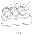
- the support device which has been generally indicated by the reference number 1, comprises a base 2 including a plurality of rotary supporting elements 3, each of which is designed for supporting a wrist watch, which is schematically illustrated by dashed lines and being indicated by the reference number 4, through latching means, not specifically shown.
- said latching means would be coupled to a drum element 5, optionally in a recess or notch formed therein, therewith is moreover made rigid a gear wheel 6.
- Said support elements 3 are so arranged that their respective gear wheels 6 are engaged with the gear wheels of adjoining supporting elements.
- At least a said gear wheel meshes with a pinion 7 of a motor geared unit 8 coupled to said base 2.
- Figures 4 and 5 show a device in which the geared motor unit 8 is substantially embedded in the base 2 and meshes with a gear wheel 66 the rotary axis of which is substantially inclined with respect to the horizontal line.
- a bracket 9 is moreover provided for suitably supporting the mentioned gear wheel 66.
- the inclined rotary axis will provide a very good simulation of the wrist motion and a possible improved exhibition to the view of the watch.
- the invention provides a supporting and winding-up device adapted to hold in an actuated or active condition the automatic wrist watch movements in an efficient manner, from a mere mechanic standpoint, while providing an improved exhibition to the view of the aesthetic aspect of the wrist watch.
- the used materials, as well as the contingent size and shapes can be any, depending on requirements.
Landscapes
- Physics & Mathematics (AREA)
- General Physics & Mathematics (AREA)
- Electromechanical Clocks (AREA)
- Connection Of Motors, Electrical Generators, Mechanical Devices, And The Like (AREA)
- Mushroom Cultivation (AREA)
- Telephone Function (AREA)
Abstract
Description
Claims (4)
- An improved device for supporting, winding-up and preserving automatic wrist watches, characterized in that said device comprises a base supporting a plurality of rotary supporting elements, each said supporting element including latching means for supporting a respective wrist watch, and a gear-motor unit for rotatably driven said supporting elements.
- A device, according to claim 1, characterized in that each said supporting element comprises a gear wheel meshing with either one or two adjoining gear wheels of corresponding respective rotary supporting elements.
- A device, according to claim 1, characterized in that said gear motor unit meshes with at least a gear wheel of a said rotary supporting element, said rotary supporting element in turn meshing with a gear wheel of an adjoining said supporting element.
- A device, according to claim 1, characterized in that each said supporting element comprises a rotary axis which is inclined with respect to a horizontal line.
Applications Claiming Priority (2)
| Application Number | Priority Date | Filing Date | Title |
|---|---|---|---|
| IT000270U ITMI20030270U1 (en) | 2003-06-09 | 2003-06-09 | SUPPORT STRUCTURE AND FOR RECHARGING PARTICULARLY FOR AUTOMATIC WRISTWATCHES |
| ITMI20030270U | 2003-06-09 |
Publications (2)
| Publication Number | Publication Date |
|---|---|
| EP1489470A2 true EP1489470A2 (en) | 2004-12-22 |
| EP1489470A3 EP1489470A3 (en) | 2004-12-29 |
Family
ID=30012549
Family Applications (1)
| Application Number | Title | Priority Date | Filing Date |
|---|---|---|---|
| EP04013420A Withdrawn EP1489470A3 (en) | 2003-06-09 | 2004-06-08 | Support and winding-up device for automatic wrist watches |
Country Status (3)
| Country | Link |
|---|---|
| US (1) | US7025495B2 (en) |
| EP (1) | EP1489470A3 (en) |
| IT (1) | ITMI20030270U1 (en) |
Cited By (5)
| Publication number | Priority date | Publication date | Assignee | Title |
|---|---|---|---|---|
| EP1669817A3 (en) * | 2004-12-09 | 2006-11-02 | Charles Agnoff | Cylinder watch winder |
| EP1780614A1 (en) * | 2005-11-01 | 2007-05-02 | Charles Agnoff | Tourbillon watch winder |
| EP2781974A1 (en) * | 2013-03-20 | 2014-09-24 | M & E Uhrenbeweger Manufaktur GmbH | Watch winder |
| WO2014146924A1 (en) * | 2013-03-20 | 2014-09-25 | M & E Uhrenbeweger Manufaktur Gmbh | Watch winder |
| EP4478134A1 (en) | 2023-06-16 | 2024-12-18 | The Swatch Group Research and Development Ltd | Apparatus for winding a clock movement of a watch |
Families Citing this family (5)
| Publication number | Priority date | Publication date | Assignee | Title |
|---|---|---|---|---|
| US7410289B2 (en) * | 2006-03-21 | 2008-08-12 | Wolf Designs, Inc. | Interlockable watchwinder |
| EP2154582A1 (en) * | 2008-08-15 | 2010-02-17 | Nivarox-FAR S.A. | Gear method for a clock piece |
| US7927009B2 (en) * | 2008-12-27 | 2011-04-19 | Abest Products Resourcing Inc. | Watch winder |
| US8408784B2 (en) * | 2011-04-20 | 2013-04-02 | Valentin Balter | Watch winder assembly with moveable attention-attracting mechanism |
| KR101352283B1 (en) * | 2013-08-19 | 2014-01-15 | 이태언 | Stand for automatic watch |
Family Cites Families (8)
| Publication number | Priority date | Publication date | Assignee | Title |
|---|---|---|---|---|
| FR1032822A (en) * | 1951-02-19 | 1953-07-06 | Procedure for winding and checking automatic watches | |
| US2863345A (en) * | 1955-08-12 | 1958-12-09 | Rene A Fiechter | Watch winding machine |
| US2926519A (en) * | 1955-10-10 | 1960-03-01 | Setterberg Fred | Mechanism for maintaining selfwinding watches wound |
| CH330909A (en) * | 1956-10-30 | 1958-06-30 | Montres Solvil & Titus S A Fab | Device for the simultaneous winding of several automatic watches |
| US2917955A (en) * | 1956-11-19 | 1959-12-22 | Sterling Multi Products Inc | Testing device for self-winding mechanisms |
| US4057958A (en) * | 1976-09-20 | 1977-11-15 | Thomas Wuntch | Watch winder |
| US5608693A (en) * | 1993-05-07 | 1997-03-04 | Richards; Jeffrey | Non-linear vibration device |
| US5988871A (en) * | 1998-01-28 | 1999-11-23 | Bonnet; Henri | Automated watch winder and method of using the same |
-
2003
- 2003-06-09 IT IT000270U patent/ITMI20030270U1/en unknown
-
2004
- 2004-06-08 US US10/864,055 patent/US7025495B2/en not_active Expired - Fee Related
- 2004-06-08 EP EP04013420A patent/EP1489470A3/en not_active Withdrawn
Cited By (6)
| Publication number | Priority date | Publication date | Assignee | Title |
|---|---|---|---|---|
| EP1669817A3 (en) * | 2004-12-09 | 2006-11-02 | Charles Agnoff | Cylinder watch winder |
| EP1780614A1 (en) * | 2005-11-01 | 2007-05-02 | Charles Agnoff | Tourbillon watch winder |
| EP2781974A1 (en) * | 2013-03-20 | 2014-09-24 | M & E Uhrenbeweger Manufaktur GmbH | Watch winder |
| WO2014146924A1 (en) * | 2013-03-20 | 2014-09-25 | M & E Uhrenbeweger Manufaktur Gmbh | Watch winder |
| EP4478134A1 (en) | 2023-06-16 | 2024-12-18 | The Swatch Group Research and Development Ltd | Apparatus for winding a clock movement of a watch |
| EP4481511A1 (en) | 2023-06-16 | 2024-12-25 | The Swatch Group Research and Development Ltd | Apparatus for winding a clock movement of a watch |
Also Published As
| Publication number | Publication date |
|---|---|
| ITMI20030270V0 (en) | 2003-06-09 |
| US20050169111A1 (en) | 2005-08-04 |
| US7025495B2 (en) | 2006-04-11 |
| EP1489470A3 (en) | 2004-12-29 |
| ITMI20030270U1 (en) | 2004-12-10 |
Similar Documents
| Publication | Publication Date | Title |
|---|---|---|
| JP4672814B2 (en) | Clock with variable time ring | |
| US7025495B2 (en) | Support and winding-up device for automatic wrist watches | |
| US6614727B2 (en) | Three dimensional children's sleeptime timer and clock device | |
| KR200278568Y1 (en) | A fashion watch | |
| US20100135126A1 (en) | Timepiece movement fitted with a vibrating alarm | |
| TWD100557S1 (en) | Watch dial | |
| CN101999098B (en) | Chronograph with dial with rotating hands | |
| JP4630135B2 (en) | A watch with a special beauty effect | |
| DE69206766T2 (en) | Noiseless alarm clock | |
| SG114591A1 (en) | Watch including a casing ring for a movement mounted in a case assembled via the bezel or via the back cover | |
| JP2009261420A (en) | Game machine | |
| US7604396B1 (en) | Wristwatch with movable movement case | |
| US4885729A (en) | Clock mechanism and display face | |
| US6773157B1 (en) | Setting assembly for an analog timepiece | |
| JP2004016270A (en) | Game machine | |
| CN214540409U (en) | Dual-system watch movement and watch | |
| JP3054943B2 (en) | Clock forward / reverse mechanism and power reserve mechanism using the same | |
| JPH0436470Y2 (en) | ||
| JP6531088B2 (en) | Operating mechanism of alarm clock | |
| CN2461028Y (en) | Clock doll transmission structure | |
| JP2006149552A (en) | Game machine | |
| JP2940807B2 (en) | Rotating decoration mechanism | |
| KR20230122321A (en) | Method for indicating present time by frosted glass tilted over rotating clock and watch using the same | |
| JP2992465B2 (en) | Alarm clock | |
| JP4277993B2 (en) | Pendulum device |
Legal Events
| Date | Code | Title | Description |
|---|---|---|---|
| PUAI | Public reference made under article 153(3) epc to a published international application that has entered the european phase |
Free format text: ORIGINAL CODE: 0009012 |
|
| PUAL | Search report despatched |
Free format text: ORIGINAL CODE: 0009013 |
|
| AK | Designated contracting states |
Kind code of ref document: A2 Designated state(s): AT BE BG CH CY CZ DE DK EE ES FI FR GB GR HU IE IT LI LU MC NL PL PT RO SE SI SK TR |
|
| AX | Request for extension of the european patent |
Extension state: AL HR LT LV MK |
|
| AK | Designated contracting states |
Kind code of ref document: A3 Designated state(s): AT BE BG CH CY CZ DE DK EE ES FI FR GB GR HU IE IT LI LU MC NL PL PT RO SE SI SK TR |
|
| AX | Request for extension of the european patent |
Extension state: AL HR LT LV MK |
|
| 17P | Request for examination filed |
Effective date: 20050310 |
|
| AKX | Designation fees paid |
Designated state(s): AT BE BG CH CY CZ DE DK EE ES FI FR GB GR HU IE IT LI LU MC NL PL PT RO SE SI SK TR |
|
| 17Q | First examination report despatched |
Effective date: 20090213 |
|
| RAP1 | Party data changed (applicant data changed or rights of an application transferred) |
Owner name: S.C.S. & CO. S.R.L. |
|
| STAA | Information on the status of an ep patent application or granted ep patent |
Free format text: STATUS: THE APPLICATION IS DEEMED TO BE WITHDRAWN |
|
| 18D | Application deemed to be withdrawn |
Effective date: 20090624 |