EP1489387A1 - Interpolation method for high resolution angular encoder and corresponding optical encoder - Google Patents
Interpolation method for high resolution angular encoder and corresponding optical encoder Download PDFInfo
- Publication number
- EP1489387A1 EP1489387A1 EP04291492A EP04291492A EP1489387A1 EP 1489387 A1 EP1489387 A1 EP 1489387A1 EP 04291492 A EP04291492 A EP 04291492A EP 04291492 A EP04291492 A EP 04291492A EP 1489387 A1 EP1489387 A1 EP 1489387A1
- Authority
- EP
- European Patent Office
- Prior art keywords
- track
- value
- angular
- iteration
- optical encoder
- Prior art date
- Legal status (The legal status is an assumption and is not a legal conclusion. Google has not performed a legal analysis and makes no representation as to the accuracy of the status listed.)
- Granted
Links
- 238000000034 method Methods 0.000 title claims abstract description 61
- 230000003287 optical effect Effects 0.000 title claims description 54
- 238000004364 calculation method Methods 0.000 claims abstract description 52
- 238000012545 processing Methods 0.000 claims description 10
- 238000006243 chemical reaction Methods 0.000 claims description 6
- 230000001360 synchronised effect Effects 0.000 claims description 3
- 238000005192 partition Methods 0.000 claims description 2
- 230000001419 dependent effect Effects 0.000 claims 1
- 230000006870 function Effects 0.000 description 23
- 230000008569 process Effects 0.000 description 10
- 238000010586 diagram Methods 0.000 description 9
- 238000011282 treatment Methods 0.000 description 8
- 108091008695 photoreceptors Proteins 0.000 description 3
- 230000000750 progressive effect Effects 0.000 description 3
- 230000003068 static effect Effects 0.000 description 3
- 238000013518 transcription Methods 0.000 description 3
- 230000035897 transcription Effects 0.000 description 3
- 230000000977 initiatory effect Effects 0.000 description 2
- 230000000630 rising effect Effects 0.000 description 2
- 238000012937 correction Methods 0.000 description 1
- 238000013479 data entry Methods 0.000 description 1
- 230000003247 decreasing effect Effects 0.000 description 1
- 230000000694 effects Effects 0.000 description 1
- 230000006872 improvement Effects 0.000 description 1
- 238000005259 measurement Methods 0.000 description 1
- 230000008520 organization Effects 0.000 description 1
- 238000010422 painting Methods 0.000 description 1
- 102220098950 rs150951102 Human genes 0.000 description 1
- 102220328617 rs1555694660 Human genes 0.000 description 1
- 102220107837 rs2268147 Human genes 0.000 description 1
- 102220169910 rs886047979 Human genes 0.000 description 1
- 239000007787 solid Substances 0.000 description 1
- 208000006379 syphilis Diseases 0.000 description 1
Images


Classifications
-
- H—ELECTRICITY
- H03—ELECTRONIC CIRCUITRY
- H03M—CODING; DECODING; CODE CONVERSION IN GENERAL
- H03M1/00—Analogue/digital conversion; Digital/analogue conversion
- H03M1/12—Analogue/digital converters
- H03M1/20—Increasing resolution using an n bit system to obtain n + m bits
- H03M1/202—Increasing resolution using an n bit system to obtain n + m bits by interpolation
- H03M1/207—Increasing resolution using an n bit system to obtain n + m bits by interpolation using a digital interpolation circuit
-
- G—PHYSICS
- G01—MEASURING; TESTING
- G01D—MEASURING NOT SPECIALLY ADAPTED FOR A SPECIFIC VARIABLE; ARRANGEMENTS FOR MEASURING TWO OR MORE VARIABLES NOT COVERED IN A SINGLE OTHER SUBCLASS; TARIFF METERING APPARATUS; MEASURING OR TESTING NOT OTHERWISE PROVIDED FOR
- G01D5/00—Mechanical means for transferring the output of a sensing member; Means for converting the output of a sensing member to another variable where the form or nature of the sensing member does not constrain the means for converting; Transducers not specially adapted for a specific variable
- G01D5/12—Mechanical means for transferring the output of a sensing member; Means for converting the output of a sensing member to another variable where the form or nature of the sensing member does not constrain the means for converting; Transducers not specially adapted for a specific variable using electric or magnetic means
- G01D5/244—Mechanical means for transferring the output of a sensing member; Means for converting the output of a sensing member to another variable where the form or nature of the sensing member does not constrain the means for converting; Transducers not specially adapted for a specific variable using electric or magnetic means influencing characteristics of pulses or pulse trains; generating pulses or pulse trains
- G01D5/24409—Interpolation using memories
-
- G—PHYSICS
- G01—MEASURING; TESTING
- G01D—MEASURING NOT SPECIALLY ADAPTED FOR A SPECIFIC VARIABLE; ARRANGEMENTS FOR MEASURING TWO OR MORE VARIABLES NOT COVERED IN A SINGLE OTHER SUBCLASS; TARIFF METERING APPARATUS; MEASURING OR TESTING NOT OTHERWISE PROVIDED FOR
- G01D5/00—Mechanical means for transferring the output of a sensing member; Means for converting the output of a sensing member to another variable where the form or nature of the sensing member does not constrain the means for converting; Transducers not specially adapted for a specific variable
- G01D5/26—Mechanical means for transferring the output of a sensing member; Means for converting the output of a sensing member to another variable where the form or nature of the sensing member does not constrain the means for converting; Transducers not specially adapted for a specific variable characterised by optical transfer means, i.e. using infrared, visible, or ultraviolet light
- G01D5/32—Mechanical means for transferring the output of a sensing member; Means for converting the output of a sensing member to another variable where the form or nature of the sensing member does not constrain the means for converting; Transducers not specially adapted for a specific variable characterised by optical transfer means, i.e. using infrared, visible, or ultraviolet light with attenuation or whole or partial obturation of beams of light
- G01D5/34—Mechanical means for transferring the output of a sensing member; Means for converting the output of a sensing member to another variable where the form or nature of the sensing member does not constrain the means for converting; Transducers not specially adapted for a specific variable characterised by optical transfer means, i.e. using infrared, visible, or ultraviolet light with attenuation or whole or partial obturation of beams of light the beams of light being detected by photocells
- G01D5/347—Mechanical means for transferring the output of a sensing member; Means for converting the output of a sensing member to another variable where the form or nature of the sensing member does not constrain the means for converting; Transducers not specially adapted for a specific variable characterised by optical transfer means, i.e. using infrared, visible, or ultraviolet light with attenuation or whole or partial obturation of beams of light the beams of light being detected by photocells using displacement encoding scales
- G01D5/3473—Circular or rotary encoders
-
- H—ELECTRICITY
- H03—ELECTRONIC CIRCUITRY
- H03M—CODING; DECODING; CODE CONVERSION IN GENERAL
- H03M1/00—Analogue/digital conversion; Digital/analogue conversion
- H03M1/12—Analogue/digital converters
- H03M1/22—Analogue/digital converters pattern-reading type
- H03M1/24—Analogue/digital converters pattern-reading type using relatively movable reader and disc or strip
- H03M1/28—Analogue/digital converters pattern-reading type using relatively movable reader and disc or strip with non-weighted coding
- H03M1/30—Analogue/digital converters pattern-reading type using relatively movable reader and disc or strip with non-weighted coding incremental
- H03M1/303—Circuits or methods for processing the quadrature signals
Abstract
Description
La présente invention concerne un procédé d'interpolation angulaire réalisé par un codeur optique haute résolution, permettant d'effectuer une mesure angulaire précise.The present invention relates to an angular interpolation method realized by a high-resolution optical coder, making it possible to perform a precise angular measurement.
Selon la figure 6, il est connu dans l'art antérieur, qu'un codeur optique de type absolu comporte un disque solidaire (21) de l'axe (23) dont l'on veut mesurer l'angle de rotation. Ce même disque (21) présente des pistes circulaires concentriques (22a, 22b et 22c), elles-mêmes comportant des zones alternativement opaques et transparentes. Ces zones sont de dimensions égales sur une piste donnée et forment des secteurs angulaires de plusieurs degrés et identiques sur chaque piste. Une lumière en provenance par exemple d'une batterie de diodes laser (24), éclaire chaque piste (22a, 22b et 22c).Le signal optique de sortie est converti en signal électrique analogique par une batterie de capteurs (25), par exemple de type photodiodes. Lorsqu'un photorécepteur reçoit les rayons lumineux, il produit un signal électrique analogique, en général, proche d'un signal sinusoïdal. Ce signal est ensuite traité par l'intermédiaire d'un convertisseur analogique / numérique ou tout autre procédé, tel qu'une méthode d'interpolation, pour obtenir un signal en créneau. La position angulaire du disque est définie par un mot binaire. Une méthode d'interpolation, connue de l'art antérieur, est représentée sur la figure 7. Cette méthode consiste en un calcul statique entre les valeurs d'un signal sinus (Y) et d'un signal cosinus (X). Ce calcul statique est réalisé par le biais d'un tableau (30) de classification de données dont les valeurs de l'angle à calculer sont prédéfinies par rapport à des valeurs de sinus et de cosinus. Ce tableau est stocké dans une mémoire de données. Un inconvénient de ce procédé d'interpolation est que, pour obtenir une meilleure précision de l'angle, il faut augmenter la taille du tableau, qui va alors prendre plus de place dans la mémoire. According to FIG. 6, it is known in the prior art that an optical coder of absolute type comprises a solid disc (21) of the axis (23) which one wants measure the angle of rotation. This same disc (21) presents tracks concentric circular rings (22a, 22b and 22c), themselves having alternately opaque and transparent areas. These areas are equal dimensions on a given track and form angular sectors several degrees and identical on each track. A light in from, for example, a battery of laser diodes (24), illuminate each track (22a, 22b and 22c). The output optical signal is converted into a signal analogue electrical system by a battery of sensors (25), for example of the type photodiodes. When a photoreceptor receives light rays, it produces an analog electrical signal, generally close to a sinusoidal signal. This signal is then processed via a converter analogue / digital or any other method, such as a method interpolation, to obtain a square-wave signal. The angular position of the disk is defined by a binary word. An interpolation method, known of the prior art is shown in FIG. 7. This method consists of a static calculation between the values of a sine signal (Y) and a signal cosine (X). This static calculation is carried out by means of a table (30) of classification of data whose values of the angle to calculate are predefined in relation to sine and cosine values. This table is stored in a data store. A disadvantage of this process interpolation is that, to obtain a better precision of the angle, it is necessary to increase the size of the painting, which will then take up more space in the memory.
Il est également connu dans l'art antérieur, que la résolution d'un codeur optique est déterminée par la précision avec laquelle le codeur est fabriqué et monté. La précision est également limitée par la précision des gravures de la piste fine, des effets de bord de la fenêtre de précision, de la précision des capteurs et du décentrage et du voilage du disque. Afin de remédier à ces imprécisions de montage, il est connu un système décrit par le brevet FR 9908159, permettant d'enrichir le mot binaire résultant de la lecture d'une première piste, dite piste fine, par des bits supplémentaires obtenus par une opération de levée de doute en V. Cette opération est réalisée par l'intermédiaire du traitement d'un signal produit par au moins une paire de récepteurs effectuant la lecture d'au moins une paire de pistes supplémentaires. En référence à la figure 9, ce codeur optique haute résolution comprend un disque (100), lui-même comportant au moins une piste fine (110) et des pistes voisines (111).La piste fine (110) est lue par quatre photodétecteurs disposés deux à deux opposés et chaque groupe de deux décalés de 90° sur le disque (100).A la lecture de cette piste, les photorécepteurs convertissent des signaux optiques en des signaux analogiques présentant au moins un signal de type sinus et un signal de type cosinus. Ces signaux vont être ensuite traités dans un convertisseur analogique / numérique, puis vont être traités dans un calculateur effectuant par exemple un calcul d'interpolation. On obtient un premier mot binaire comportant par exemple 10 bits, dont le bit de poids faible correspond à un signal en créneau C. Pour obtenir une meilleure correction par exemple des erreurs de décentrage du disque, le mot binaire est enrichi d'au moins un bit de levé de doute. Plus le mot binaire contient de bits de levée de doute, plus la résolution du codeur est bonne. En référence à la figure 8, un bit de levée de doute est produit par la lecture d'une paire de pistes supplémentaires situées par exemple de part et d'autre de la piste fine. Chaque piste voisine est lue par un photodétecteur. Le signal électrique produit par chaque photorécepteur des pistes voisines est également traité pour obtenir un signal en créneau. On obtient deux signaux en créneaux respectivement, A et B, décalés entre eux d'une demi-période. Une mémoire programmable effectue l'équation algorithmique de la levée de doute entre le signal fourni par la piste fine et ceux fournis par les pistes voisines. Cette équation est la suivante : « Si C=1 alors D=A sinon D=B », D étant le bit résultant de la levée de doute. La figure 8 représente les chronogrammes représentatifs des différents signaux, A, B, C et D. On obtient un bit de levée de doute D permettant d'enrichir le mot binaire obtenu par la lecture de la piste fine. En référence au brevet FR 9908159, on peut également enrichir le mot binaire en minimisant le nombre de photo-détecteurs, disposés sur le disque. Ainsi avec 4 photo-détecteurs, on peut obtenir 3 bits de levée de doute. Cette amélioration est obtenue par des calculs de logique combinatoire et l'équation de la levée de doute précédemment citée. Cependant, pour un mot binaire de 26 bits par exemple il faut, 4 photo-détecteurs pour lire la piste fine qui fournit, par exemple un mot de 10 bits, et pour obtenir les bits de levée de doute restant, il faut au moins 30 photo-détecteurs. Il peut s'avérer nécessaire de doubler le nombre de photo-détecteur, permettant ainsi de réaliser une moyenne sur les résultats obtenus. Cette moyenne permet d'obtenir une meilleure précision du résultat. Ce nombre important de photo-détecteurs, utilisés pour la lecture de la piste fine et des pistes supplémentaires, est un inconvénient majeur de ce codeur optique de haute résolution.It is also known in the prior art that the resolution of a optical encoder is determined by the accuracy with which the encoder is manufactured and mounted. Precision is also limited by the accuracy of engravings of the fine track, precision edge effects of the window, the accuracy of the sensors and the decentering and the fogging of the disk. In order to remedy these inaccuracies of assembly, it is known a system described by patent FR 9908159, making it possible to enrich the binary word resulting from the reading a first track, called fine track, by additional bits obtained by an operation to remove doubt in V. This operation is realized by the processing of a signal produced by at least one pair of receivers playing at least one pair of tracks additional. With reference to FIG. 9, this high optical encoder resolution includes a disk (100), itself having at least one fine track (110) and neighboring tracks (111) .The fine track (110) is read by four photodetectors arranged two to two opposite and each group of two offset by 90 ° on the disc (100). When playing this track, the photoreceptors convert optical signals into signals with at least one sine-type signal and one type signal cosine. These signals will then be processed in a converter analog / digital, then will be processed in a calculator for example an interpolation calculation. We get a first binary word for example comprising 10 bits, the least significant bit of which corresponds to a signal in slot C. To obtain a better correction for example of disc decenter errors, the binary word is enriched by at least one bit of raising doubt. The longer the binary word contains doubt-raising bits, the more the encoder resolution is good. With reference to FIG. 8, a rising bit of doubt is produced by reading a pair of additional tracks located for example on both sides of the thin track. Each neighboring track is read by a photodetector. The electrical signal produced by each photoreceptor of neighboring tracks is also treated to get a niche signal. We obtain two signals in slots respectively, A and B, offset from each other by half a period. Programmable memory performs the algorithmic equation of the removal of doubt between the signal provided by the fine track and those provided by the neighboring tracks. This equation is the following: "If C = 1 then D = A otherwise D = B", where D is the bit resulting from the removal of doubt. Figure 8 represents representative chronograms of different signals, A, B, C and D. We obtain a bit of doubt D to enrich the binary word obtained by reading the fine track. In reference to patent FR 9908159, it is also possible to enrich the binary word by minimizing the number of photodetectors arranged on the disk. So with 4 photo-detectors, we can obtain 3 bits of doubt. This improvement is achieved by combinatorial logic calculations and the equation of the above-mentioned doubt. However, for one word binary of 26 bits for example it is necessary, 4 photo-detectors to read the fine track which provides, for example a 10-bit word, and to obtain the rising bits of doubt remains, it takes at least 30 photo-detectors. It can be necessary to double the number of photodetectors, thus allowing average the results obtained. This average allows to obtain a better precision of the result. This large number of photo-detectors, used for playing the fine track and tracks additional, is a major disadvantage of this high optical encoder resolution.
La présente invention a pour but de pallier certains inconvénients de l'art antérieur en proposant un procédé d'interpolation angulaire, par calcul dynamique, associé à un codeur optique haute résolution. Ce procédé permet de diminuer le nombre de portes logiques dont les signaux sont utilisés par le codeur. Le codeur optique propose, en utilisant ce procédé d'interpolation angulaire, de diminuer le nombre de photodétecteurs utilisés pour la lecture des pistes internes du disque du codeur optique haute résolution.The present invention aims to overcome certain disadvantages of the prior art by proposing an angular interpolation method, by calculation dynamic, associated with a high resolution optical encoder. This process reduces the number of logic gates whose signals are used by the encoder. The optical encoder proposes, using this method angular interpolation, to reduce the number of photodetectors used for reading the internal tracks of the high optical encoder disc resolution.
Ce but est atteint par un procédé d'interpolation angulaire, effectué par un codeur optique, ledit codeur optique comprenant au moins, un disque comportant au moins une piste circulaire concentrique formée par des zones alternativement opaques et transparentes, une source lumineuse éclairant la piste, des capteurs permettant de convertir un signal optique généré par la source lumineuse et le disque en un signal analogique, un moyen de convertir un signal analogique en un signal numérique et uncalculateur réalisant le traitement des données, le procédé d'interpolation angulaire est caractérisé en ce qu'il comprend les étapes suivantes :
- la lecture et la saisie des valeurs numériques Y 0 et X 0 des signaux générés par la source lumineuse et la piste circulaire, les signaux analogiques étant numérisés par un moyen de convertir un signal analogique en un signal numérique,
- le calcul dynamique de l'interpolation angulaire réalisé sur une période angulaire allant de -90° à 90°, ledit calcul d'interpolation étant sensiblement équivalent à un calcul par itération, avec chaque itération « i » comprenant, la détermination d'un signe « d » en fonction de valeurs Xi -1 et Yi -1 précédemment calculées ou lues dans l'itération « i-1 » précédente, le calcul de nouvelles valeurs Xi et Yi permettant de déterminer le signe « d » à utiliser dans la prochaine itération « i+1 », et le calcul d'une valeur Zi s'approchant, à chaque itération, de la valeur finale de l'angle à connaítre.
- la détermination de la zone de 180° situant la position de l'angle, permettant d'obtenir un résultat sur une période angulaire de 360°, ledit résultat étant présenté par un mot binaire comprenant un nombre de bits prédéfinis.
- reading and entering the digital values Y 0 and X 0 of the signals generated by the light source and the circular track, the analog signals being digitized by means of converting an analog signal into a digital signal,
- the dynamic calculation of the angular interpolation performed over an angular period ranging from -90 ° to 90 °, said interpolation calculation being substantially equivalent to an iterative calculation, with each iteration "i" comprising, the determination of a sign "D" according to values X i -1 and Y i -1 previously calculated or read in the previous iteration "i-1", the calculation of new values X i and Y i for determining the sign "d" to use in the next iteration "i + 1", and calculating a value Z i approaching, at each iteration, the final value of the angle to be known.
- the determination of the 180 ° zone locating the position of the angle, making it possible to obtain a result over an angular period of 360 °, said result being presented by a binary word comprising a number of predefined bits.
Selon une autre particularité, le procédé d'interpolation angulaire effectue la saisie de données numériques Y 0 et X 0 lors de la première étape du calcul d'interpolation angulaire, lesdites données numériques résultant de la lecture de signaux sensiblement identiques à des signaux sinusoïdaux respectivement de type sinus et cosinus. According to another feature, the angular interpolation method performs the input of digital data Y 0 and X 0 during the first step of the angular interpolation calculation, said digital data resulting from the reading of substantially identical signals to sinusoidal signals respectively sinus and cosine type.
Selon une autre particularité, la valeur Xi de l'itération « i », « i » étant différente de la valeur nulle, est calculée en fonction des valeurs Xi -1 et Yi -1 calculées lors de l'itération « i -1 » précédente, et en fonction du signe « d », déterminé lors de l'itération « i ».According to another particularity, the value X i of the iteration "i", "i" being different from the zero value, is calculated as a function of the values X i -1 and Y i -1 calculated during the iteration "i". -1 "above, and according to the sign" d ", determined during the iteration" i ".
Selon une autre particularité, la valeur Yi de l'itération « i », « i » étant différente de la valeur nulle, est calculée en fonction des valeurs Xi -1 et Yi -1 calculées lors de l'itération « i-1 » précédente, et en fonction du signe « d » déterminé lors de l'itération « i ».According to another particularity, the value Y i of the iteration "i", "i" being different from the zero value, is calculated as a function of the values X i -1 and Y i -1 calculated during the iteration "i -1 "above, and according to the sign" d "determined during the iteration" i ".
Selon une autre particularité, le signe « d » est déterminé lors de
l'étape de saisie des données, par un moyen de comparaison de la valeur
des données numérique Y 0 et X 0, en fonction des conditions suivantes : d =
1 si X 0 < 0 et Y 0 < 0 sinon
d = -1.According to another particularity, the sign "d" is determined during the data entry step, by means of comparing the value of the digital data Y 0 and X 0 , as a function of the following conditions: d = 1 if X 0 <0 and Y 0 <0 otherwise
d = -1.
Selon une autre particularité, le signe « d » est déterminé lors des itérations « i », « i » étant différente de la valeur nulle, par un moyen de comparaison de la valeur des données Xi -1 et Yi -1 déterminées dans l'itération précédente « i-1 », en fonction des conditions suivantes : d = 1 si Xi -1 < 0 et Yi -1 < 0 sinon d = -1.According to another particularity, the sign "d" is determined during the iterations "i", "i" being different from the zero value, by means of comparing the value of the data X i -1 and Y i -1 determined in the previous iteration "i-1", according to the following conditions: d = 1 if X i -1 <0 and Y i -1 <0 otherwise d = -1.
Selon une autre particularité, la valeur Z i de l'itération « i », « i » étant différente de la valeur nulle, est calculée en fonction du signe « d » déterminé dans l'itération « i » et soit, d'une constante prédéfinie ou soit, de la valeur Z i -1 calculée lors de l'itération « i-1 » précédente.According to another particularity, the value Z i of the iteration "i", "i" being different from the zero value, is calculated according to the sign "d" determined in the iteration "i" and is, of a predefined constant or of the value Z i -1 calculated during the previous iteration "i-1".
Selon une autre particularité, le nombre d'itérations est prédéfini, permettant ainsi de prédéfinir les constantes utilisées dans le calcul et ainsi de diminuer le temps de calcul d'interpolation réalisé par le calculateur, et de diminuer le nombre de portes logiques dont les signaux sont utilisés par le calculateur du codeur optique, tout en obtenant un résultat précis. According to another particularity, the number of iterations is predefined, allowing to predefine the constants used in the calculation and thus to reduce the interpolation calculation time carried out by the computer, and to reduce the number of logic gates whose signals are used by the calculator of the optical encoder, while obtaining a precise result.
Selon une autre particularité, la valeur X ne varie plus et n'est plus calculée dès lors, qu'elle est égale à une valeur proche de zéro, ladite valeur X restant la même dans les itérations suivantes.According to another particularity, the value X no longer varies and is no longer calculated, that it is equal to a value close to zero, said value X remaining the same in the following iterations.
Selon une autre particularité, le procédé d'interpolation angulaire calcule les valeurs X, Y et Z pour obtenir des valeurs entières, les valeurs en décimales n'étant pas significatives pour la précision de l'angle, ledit calcul en valeur entière permettant de diminuer le nombre de portes logiques dont les signaux sont utilisés par le calculateur du codeur optique.According to another feature, the method of angular interpolation calculates the X, Y and Z values to obtain integer values, the values in decimal places not being significant for the accuracy of the angle, the calculation as an integer value to reduce the number of logic gates the signals are used by the optical encoder computer.
Selon une autre particularité, l'erreur de calcul, obtenue avec un tel procédé d'interpolation angulaire, est inférieure à 1.5en, sachant que e = 2- b , b étant le nombre de bits utilisés pour représenter un nombre, et n étant égal au nombre d'itérations prédéfinies.According to another particularity, the calculation error, obtained with such an angular interpolation method, is less than 1.5en, knowing that e = 2 - b , b being the number of bits used to represent a number, and n being equal to the number of predefined iterations.
Selon une autre particularité, la zone de 180° situant la position de l'angle, est déterminée par le bit de poids fort d'un mot binaire obtenu par la conversion analogique numérique d'un signal sinusoïdal de type sinus ou cosinus résultant de la lecture de la piste, ladite conversion étant réalisée par le moyen de convertir un signal analogique en un signal numérique.According to another particularity, the zone of 180 ° locating the position of the angle, is determined by the most significant bit of a binary word obtained by the digital analog conversion of a sinusoidal sinusoidal signal or cosine resulting from the reading of the track, said conversion being performed by the means of converting an analog signal into a digital signal.
Un autre but est de proposer un codeur optique de haute résolution
comprenant un disque comportant au moins deux pistes, dont une piste de
division fine et une piste de division plus grossière, le partage en division de
chaque piste étant un multiple de la piste précédente, les dites pistes sont
lues chacune par quatre photodétecteurs permettant d'obtenir par piste, des
signaux sensiblement sinusoïdaux décalés de 90° chacun, ces signaux étant
ensuite numérisés par un moyen de convertir un signal analogique en un
signal numérique pour obtenir des coordonnées initiales d'angle de positions
qui sont directement envoyés vers un calculateur pour être traités, le codeur
optique haute résolution étant caractérisé en ce que le calculateur effectue
un procédé dynamique d'interpolation angulaire comportant en entrée les
signaux sinusoïdaux générés par la lecture de chaque piste individuelle et
convertis en signaux numériques, le calculateur produisant une valeur
d'angle numérique pour chaque piste individuelle, ces valeurs d'angles étant
ajoutées les unes aux autres et traitées pour former un mot numérique
représentant la position angulaire absolue du disque.
Codeur optique de haute résolution comprenant un disque (1) comportant au
moins deux pistes (2a et 2c), dont une piste de division fine (2c) et une piste
de division plus grossière (2a), le partage en division de chaque piste étant
un multiple de la piste précédente, les dites pistes (2a et 2c) sont lues
chacune par quatre photodétecteurs (4, 5, 6 et 7) permettant d'obtenir par
piste, des signaux sensiblement sinusoïdaux décalés de 90° chacun, ces
signaux étant ensuite numérisés par un moyen de convertir un signal
analogique en un signal numérique (14) pour obtenir des coordonnées
initiales d'angle de positions (X0 et Y0), le codeur optique haute résolution
étant caractérisé en ce que le calculateur réalise un procédé dynamique
d'interpolation angulaire à partir de signaux sinusoïdaux générés par la
lecture de chaque piste individuelle (2a et 2c), permettant d'obtenir une
valeur d'angle numérique pour chaque piste individuelle (2a et 2c), ces
valeurs étant ajoutées les unes aux autres et traitées pour former un mot
numérique représentant la position angulaire absolue du disque.Another object is to propose a high resolution optical encoder comprising a disc comprising at least two tracks, including a fine division track and a coarser division track, the division division of each track being a multiple of the previous track, the said tracks are each read by four photodetectors making it possible to obtain, by track, substantially sinusoidal signals offset by 90 ° each, these signals being then digitized by means of converting an analog signal into a digital signal to obtain initial coordinates of an angle of positions which are directly sent to a computer to be processed, the high resolution optical encoder being characterized in that the computer performs a dynamic method of angular interpolation comprising as input the sinusoidal signals generated by the reading of each individual track and converted in digital signals, the computer producing a value of a numeric code for each individual track, these angle values being added to each other and processed to form a digital word representing the absolute angular position of the disc.
High resolution optical encoder comprising a disk (1) having at least two tracks (2a and 2c), including a fine division track (2c) and a coarser division track (2a), the divisional partition of each track being a multiple of the preceding track, the said tracks (2a and 2c) are each read by four photodetectors (4, 5, 6 and 7) making it possible to obtain, by track, substantially sinusoidal signals shifted by 90 ° each, these signals being then digitized by means of converting an analog signal into a digital signal (14) to obtain initial position angle coordinates (X0 and Y0), the high resolution optical encoder being characterized in that the computer performs a dynamic process of angular interpolation from sinusoidal signals generated by the reading of each individual track (2a and 2c), making it possible to obtain a numerical angle value for each individual track (2a and 2c), these values being added to each other and processed to form a digital word representing the absolute angular position of the disk.
Selon une autre particularité, le calculateur comporte des moyens de réaliser le procédé d'interpolation angulaire, ces moyens comprenant un moyen de détermination de la valeur angulaire permettant d'obtenir une valeur d'angle numérique pour chaque piste individuelle, un moyen de déterminer dans une itération i l'opération, addition ou soustraction, de la coordonnée orthogonale à celle calculée dans l'itération précédente i-1, cette opération étant associée à une condition de détermination d'un signe obtenue par un moyen de comparaison des coordonnées de l'itération précédente avec une valeur constante et des moyens d'utiliser le signe de l'opération ainsi déterminée pour ajouter ou soustraire un coefficient dépendant du niveau d'itération à la valeur précédente d'angle pour obtenir une valeur d'angle à connaítre. According to another particularity, the calculator comprises means for performing the angular interpolation method, these means comprising a means of determining the angular value to obtain a numerical angle value for each individual track, a means of to determine in an iteration i the operation, addition or subtraction, of the coordinate orthogonal to that computed in the previous iteration i-1, this operation being associated with a condition for determining a sign obtained by a means of comparing the coordinates of the iteration previous with a constant value and ways to use the sign of the operation thus determined to add or subtract a coefficient depending on the iteration level at the previous angle value to get an angle value to know.
Selon une autre particularité, le traitement des signaux numériques, de forme sensiblement sinusoïdale arrivant dans le calculateur, fournit un mot binaire correspondant à la lecture d'une piste, ledit mot binaire comprenant un premier bit représentatif de la variation des zones opaques et transparentes de la piste lue et les autres bits restants étant représentatifs de la valeur d'angle numérique fournie par un calcul dynamique d'interpolation angulaire.According to another particularity, the digital signal processing, of substantially sinusoidal shape arriving in the calculator, provides a binary word corresponding to the reading of a track, said binary word comprising a first bit representative of the variation of the opaque zones and of the track read and the remaining bits being representative of the numerical angle value provided by a dynamic interpolation calculation angular.
Selon une autre particularité, les mots binaires, résultant du traitement des signaux numériques générés lors de la lecture de chaque piste individuelle, sont traités de manière combinatoire les uns aux autres, permettant d'obtenir un mot binaire final synchronisé, représentatif de la position angulaire absolue du disque, ledit mot binaire final étant constitué de telle sorte que les bits de poids faibles correspondent à la valeur angulaire représentative de la lecture de la piste de division la plus fine et les bits de poids fort correspondent à la valeur angulaire représentative de la lecture de la piste de division la moins fine.According to another particularity, the binary words resulting from the treatment digital signals generated during playback of each track individual, are treated in a combinatorial way with each other, to obtain a synchronized final binary word, representative of the absolute angular position of the disk, said final binary word consisting of so that the least significant bits correspond to the angular value representative of the reading of the finest divisional track and the bits of highest weight correspond to the representative angular value of the reading of the least fine division track.
Selon une autre particularité, le codeur optique de haute résolution comprend un moyen de convertir un signal analogique en un signal numérique multiplexé permettant de numériser les signaux de forme sensiblement sinusoïdale, générés par la lecture de chaque piste individuelle en fonction du multiplexage commandé par le calculateur.According to another particularity, the high resolution optical encoder includes means for converting an analog signal into a signal multiplexed digital device for digitizing shape signals substantially sinusoidal, generated by reading each individual track according to the multiplexing controlled by the computer.
Selon une autre particularité, le codeur optique de haute résolution comprend un système de traitement de données multiplexé, permettant de réaliser le même procédé dynamique d'interpolation angulaire à partir de tous les signaux sinusoïdaux générés par la lecture de chaque piste individuelle.According to another particularity, the high resolution optical encoder includes a multiplexed data processing system, allowing perform the same dynamic process of angular interpolation from all the sinusoidal signals generated by the reading of each track individual.
Selon une autre particularité, le codeur optique de haute résolution comprend un disque pouvant comporter plus de deux pistes, les pistes étant de division différente plus ou moins fine, et étant disposées les unes par rapport aux autres de manière concentrique sur le disque, permettant que le partage en division de chaque piste soit un multiple de la piste précédente.According to another particularity, the high resolution optical encoder includes a disk that may have more than two tracks, the tracks being of different divisions more or less fine, and being arranged some by to others in a concentric way on the disc, allowing the division of each track is a multiple of the previous track.
Selon une autre particularité, la piste de division la moins fine permet de générer lors de sa lecture, au moins un signal de forme sensiblement sinusoïdale dont la période correspond à un tour de rotation du disque codé.According to another particularity, the least fine division track allows generate during reading, at least one form signal substantially sinusoidal whose period corresponds to a rotation of the encoded disk.
Selon une autre particularité, la piste de division la moins fine est de forme progressive, permettant de générer par sa lecture un signal de forme sensiblement sinusoïdale.According to another particularity, the least fine division track is progressive form, making it possible to generate a shape signal by reading it substantially sinusoidal.
D'autres particularités et avantages de la présente invention apparaítront plus clairement à la lecture de la description ci-après, faite en référence aux dessins annexés, dans lesquels :
- La figure 1 représente le schéma simplifié d'un disque codé, ledit schéma étant utilisé pour expliquer clairement les étapes du procédé dynamique d'interpolation angulaire, selon l'invention ;
- la figure 2 représente le schéma simplifié d'un système d'exploitation d'un codeur optique, ledit schéma étant utilisé pour expliquer clairement les étapes du procédé dynamique d'interpolation angulaire, selon l'invention;
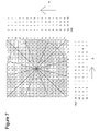
- la figure 3 représente le schéma d'un disque codé, selon l'invention.
- la figure 4 représente un schéma spécifique de la composition d'un mot binaire comprenant la valeur numérique d'un angle, ledit mot binaire résultant du calcul dynamique d'interpolation angulaire, selon l'invention,
- la figure 5 représente le schéma du système d'exploitation du codeur optique de haute résolution utilisant le procédé dynamique d'interpolation angulaire de l'invention ;
- la figure 6 représente le schéma d'un codeur optique connu de l'art antérieur ;
- la figure 7 représente le schéma représentatif du procédé statique d'interpolation angulaire connu de l'art antérieur ;
- la figure 8 représente les chronogrammes représentatifs de l'équation de levée de doute en V connue de l'art antérieur ;
- la figure 9 représente une vue de disposition de pistes concentriques sur un disque codé, permettant de réaliser une levée de doute en V connue de l'art antérieur.
- FIG. 1 represents the simplified diagram of a coded disk, said diagram being used to explain clearly the steps of the dynamic method of angular interpolation, according to the invention;
- FIG. 2 represents the simplified diagram of an operating system of an optical encoder, said diagram being used to explain clearly the steps of the dynamic method of angular interpolation, according to the invention;
- FIG. 3 represents the diagram of a coded disk, according to the invention.
- FIG. 4 represents a specific diagram of the composition of a binary word comprising the numerical value of an angle, said binary word resulting from the dynamic calculation of angular interpolation, according to the invention,
- FIG. 5 represents the diagram of the operating system of the high resolution optical encoder using the dynamic method of angular interpolation of the invention;
- FIG. 6 represents the diagram of an optical encoder known from the prior art;
- FIG. 7 represents the representative diagram of the static method of angular interpolation known from the prior art;
- FIG. 8 represents the representative chronograms of the V-doubt queuing equation known from the prior art;
- FIG. 9 represents an arrangement view of concentric tracks on a coded disc, making it possible to carry out a V-doubt raising known from the prior art.
La présente invention concerne, en particulier, un procédé de calcul d'interpolation d'angle permettant de calculer l'angle formé, par exemple, par un bras mécanique autour d'un axe. En se référant aux figures 1 et 2, le codeur optique utilisé dans le début de la description est un codeur simplifié permettant une meilleure compréhension du procédé, selon l'invention. Ce codeur optique comprend un disque (1), disposé sur un axe (3), le disque comportant une piste fine (2), ladite piste étant lue par quatre photodétecteurs (4, 5, 6 et 7) disposés autour de la piste de manière à fournir, après lecture de la piste, des signaux sinusoïdaux déphasés de 90°. Les quatre signaux sinusoïdaux correspondent respectivement à un signal sinus (8), à un signal sinus inversé (9), à un signal cosinus (10) et à un signal cosinus inversé (11).Chaque paire de signal sinus (sinus et sinus inversé) et cosinus (cosinus et cosinus inversé) est ensuite comparé dans un amplificateur différentiel (12 et 13) pour en ressortir un signal sinus et un signal cosinus, obtenus sans un décalage généré par le courant continu. Ces deux signaux sont ensuite numérisés, par exemple, dans un convertisseur numérique analogique (14) et après numérisation, les signaux entrent dans un calculateur (15) qui réalise le procédé d'interpolation.The present invention relates, in particular, to a calculation method angle interpolation method for calculating the angle formed, for example, by a mechanical arm around an axis. Referring to Figures 1 and 2, the optical encoder used in the beginning of the description is a simplified encoder allowing a better understanding of the process according to the invention. This optical encoder comprises a disk (1) disposed on an axis (3), the disk having a thin track (2), said track being read by four photodetectors (4, 5, 6 and 7) arranged around the track so as to provide, after reading the track, sinusoidal signals out of phase by 90 °. The four sinusoidal signals correspond respectively to a signal sinus (8), an inverted sine signal (9), a cosine signal (10) and a signal inverted cosine (11). Each pair of sinus signal (sinus and inverted sinus) and cosine (cosine and inverted cosine) is then compared in a differential amplifier (12 and 13) to output a sinus signal and a cosine signal, obtained without a shift generated by the direct current. These two signals are then digitized, for example, in a converter (14) and after digitization, the signals enter a calculator (15) that performs the interpolation method.
Le procédé de calcul d'interpolation, selon l'invention, comprend au moins trois étapes :
- une étape de saisie des valeurs initiales (X0, Y0),
- une étape de calcul d'interpolation angulaire en fonction des valeurs initiales (X0, Y0) comprenant également d'autres sous étapes, ledit calcul permettant d'obtenir un résultat angulaire positionné sur une période angulaire allant de -90° à 90°,
- et enfin une étape permettant d'obtenir le résultat de la valeur angulaire sur une période de 360°.
- a step of entering the initial values (X0, Y0),
- an angular interpolation calculation step as a function of the initial values (X0, Y0) also comprising other sub-steps, said calculation making it possible to obtain an angular result positioned over an angular period ranging from -90 ° to 90 °,
- and finally a step to obtain the result of the angular value over a period of 360 °.
Le procédé, selon l'invention, réalise un calcul sensiblement équivalent à un calcul d'itération. Cependant les itérations, calculées dans la présente invention, ne sont pas identiques les unes des autres, permettant ainsi de travailler avec des constantes prédéfinis afin de minimiser ie temps de calcul et le nombre de portes logiques utilisées par le calculateur.The method according to the invention performs a calculation substantially equivalent to an iteration calculation. However the iterations, calculated in the present invention, are not identical to each other, allowing thus working with predefined constants to minimize the time calculation and the number of logic gates used by the computer.
La première étape du procédé, selon l'invention, concerne la lecture et la saisie des valeurs numériques Y0 et X0 générées par le convertisseur analogique numérique. Ces valeurs correspondent respectivement aux valeurs numériques des signaux analogiques convertis. Ces valeurs représentent respectivement les valeurs numériques correspondant au signal cosinus (X0) et du signal sinus (Y0) lus par les phototransistors disposés sur la piste fine. Ainsi le bras mécanique représenté dans un plan orthogonal d'axe des ordonnées y et d'axe des abscisses x est à une position M. Le point M a pour coordonnées, le point d'intersection (X0) entre la droite droit passant par M orthogonale à l'axe x et l'axe y et le point d'intersection (Y0) entre la droite passant par M orthogonale à l'axe x et l'axe y.The first step of the method, according to the invention, concerns the reading and the input of the numerical values Y0 and X0 generated by the converter digital analog. These values correspond respectively to digital values of the converted analog signals. These values represent respectively the numerical values corresponding to the signal cosine (X0) and the sinus signal (Y0) read by the phototransistors arranged on the fine track. Thus the mechanical arm represented in an orthogonal plane y-axis and x-axis x is at a position M. point M a for coordinates, the point of intersection (X0) between the right line passing through M orthogonal to the x-axis and the y-axis and the point of intersection (Y0) between the line passing through M orthogonal to the x axis and the y axis.
La deuxième étape du procédé, selon l'invention, concerne le calcul
de l'interpolation angulaire, permettant d'obtenir la valeur d'un angle, borné
sur une période angulaire allant de « -90° » à « 90° ».
Ci-dessous, un exemple d'algorithme de ce calcul d'interpolation est
présenté. Cet exemple correspond à un calcul d'interpolation permettant 13
itérations. Ce calcul peut être également réalisé avec un nombre d'itérations
inférieur ou supérieur au nombre 13. La deuxième étape du procédé, selon
l'invention, est décrite en référence à l'exemple présenté ci-dessous :
Below, an example of an algorithm of this interpolation calculation is presented. This example corresponds to an interpolation calculation allowing 13 iterations. This calculation can also be performed with a number of iterations less than or greater than the
Dans l'exemple ci-dessus, les données Xi et Yi correspondent à des valeurs calculées à partir des valeurs Xi-1 et Yi-1 calculées ou lues dans les itérations précédentes. La donnée « d » correspond à un signe, défini suivant les valeurs Xi-1 et Yi-1 calculées ou lues dans les itérations précédentes. La donnée Zi correspond à la valeur s'approchant à chaque calcul d'itération de la valeur de l'angle à connaítre. Les valeurs γ_i, α_i et β_i sont des constantes prédéfinies. Pour réaliser ce procédé d'interpolation le calculateur comprend un moyen de détermination de l'opération, addition ou soustraction, des coordonnées de chaque axe x et y (Xi et Yi) dans l'itération i en fonction des coordonnées (Xi-1 et Yi-1) calculées dans l'itération i-1 et en fonction également d'une condition de détermination du signe d de l'opération basée sur les coordonnées de l'itération i-1. Le calculateur comprend également un moyen de détermination de la valeur angulaire permettant d'obtenir une valeur d'angle numérique pour chaque piste individuelle du disque. Ce moyen de détermination comporte un moyen d'utiliser le signe « d » ainsi déterminée pour ajouter ou soustraire un coefficient β_i dépendant du niveau d'itération à la valeur précédente d'angle Zi-1 pour obtenir la valeur d'angle à connaítre Zi.In the example above, the data Xi and Yi correspond to values calculated from the values Xi-1 and Yi-1 calculated or read in the previous iterations. The data "d" corresponds to a sign, defined according to the values Xi-1 and Yi-1 calculated or read in the previous iterations. The datum Zi corresponds to the value approaching each iteration calculation of the value of the angle to be known. The values γ_i, α_i and β_i are predefined constants. To carry out this interpolation process, the calculator includes means for determining the operation, addition or subtraction, coordinates of each axis x and y (Xi and Yi) in the iteration i as a function of the coordinates (Xi-1 and Yi-1) calculated in the iteration i-1 and also depending on a condition for determining the sign d of the operation based on the coordinates of the iteration i-1. The calculator also includes means for determining the angular value to obtain a numerical angle value for each track individual disc. This means of determination comprises a means use the 'd' sign thus determined to add or subtract a coefficient β_i depending on the iteration level at the previous angle value Zi-1 to get the angle value to know Zi.
Chaque itération se base sur des phases de calcul sensiblement
identique. La première phase de calcul d'une itération est la détermination du
signe « d » en fonction des valeurs Xi et Yi calculées lors de l'itération
précédente « i-1 » ou des valeurs X0 et Y0 saisies lors de la première étape
réalisée par le procédé, selon l'invention. La détermination du signe « d » est
réalisée par un moyen de comparaison des valeurs Xi et Yi calculées lors de
l'itération précédente « i-1 » selon des conditions de détermination. Ce
moyen de comparaison est compris dans le calculateur. Ainsi en se référant
à l'exemple ci-dessus, lors de la première itération, le signe « d » est
déterminé par les valeurs X0 et Y0 saisies lors de la première étape, réalisée
par le procédé, selon l'invention. Les conditions de détermination de « d »
sont : d= 1 si X 0 < 0 et Y 0 < 0 sinon d= -1. Lors des itérations suivantes, le
signe « d » est déterminé en fonction des valeurs Xi-1 et Yi-1 calculées lors
des itérations précédentes. Par exemple dans l'itération numéro 2, « d » est
défini suivant X1 et Y1. Les conditions de détermination de « d » dans une
itération « i » sont : d= 1 si Xi -1 < 0 et Yi -1 < 0 sinon d= -1.Each iteration is based on substantially identical calculation phases. The first phase of calculating an iteration is the determination of the sign "d" as a function of the values Xi and Yi calculated during the previous iteration "i-1" or the values X0 and Y0 entered during the first step performed by the process according to the invention. The determination of the sign "d" is carried out by means of comparing the values Xi and Yi calculated during the previous iteration "i-1" according to determination conditions. This means of comparison is included in the calculator. Thus, with reference to the example above, during the first iteration, the sign "d" is determined by the values X0 and Y0 entered during the first step, performed by the method according to the invention. The conditions for determining "d" are: d = 1 if X 0 <0 and Y 0 <0 otherwise d = -1. During the following iterations, the sign "d" is determined according to the values Xi-1 and Yi-1 calculated during the previous iterations. For example, in
La deuxième phase de calcul d'une itération « i », consiste à
déterminer la valeur Xi en fonction des valeurs Xi-1 et Yi-1 calculées lors des
itérations précédentes et en fonction du signe « d » défini lors de la première
phase de l'itération numéro i. Lors de cette deuxième phase de calcul, le
calculateur utilise un moyen de déterminer l'opération, dans l'exemple une
addition, associée au signe précédemment déterminé « d » pour calculer la
coordonnée Xi. En se référant à l'exemple ci-dessus, la valeur de X1 est
obtenue en fonction des valeurs X0 et Y0 saisies lors de la première étape,
réalisée par le procédé, selon l'invention et en fonction du signe « d » défini
lors de la première phase de l'itération numéro 1. A partir de l'itération
numéro 6, Xi est une valeur proche de zéro. Cette valeur ne varie plus et
reste, lors des calculs des itérations suivantes, à la valeur de X5.
La troisième phase de calcul d'une itération « i », consiste à déterminer la
valeur Yi en fonction des valeurs Xi-1 et Yi-1 calculées lors des itérations
précédentes et du signe « d » défini lors de ia première phase de l'itération
numéro « i ». Lors de cette troisième phase de calcul, le calculateur utilise un
moyen de déterminer l'opération, dans l'exemple une soustraction, associée
au signe précédemment déterminé « d » pour calculer la coordonnée Yi. En
se référant à l'exemple ci-dessus, la valeur de Y1 est obtenue en fonction
des valeurs X0 et Y0 saisies lors de la première étape, réalisée par le
procédé, selon l'invention et en fonction du signe « d » défini lors de la
première phase de l'itération numéro « 1 ». La détermination de la valeur Yi
et du signe « d » dans les itérations 6 à 13 est réalisée en fonction de la
valeur X5 et non la valeur Xi-1.The second phase of calculating an iteration "i" consists in determining the value Xi as a function of the values Xi-1 and Yi-1 calculated during the previous iterations and as a function of the sign "d" defined during the first phase of the iteration number i. During this second calculation phase, the computer uses a means of determining the operation, in the example an addition, associated with the previously determined sign "d" to calculate the coordinate Xi. Referring to the example above, the value of X1 is obtained as a function of the values X0 and Y0 entered during the first step, carried out by the method according to the invention and as a function of the sign "d" defined during of the first phase of
The third phase of calculating an iteration "i" consists in determining the value Yi as a function of the values Xi-1 and Yi-1 calculated during the previous iterations and the sign "d" defined during the first phase of the iteration number "i". During this third calculation phase, the computer uses a means of determining the operation, in the example a subtraction, associated with the previously determined sign "d" to calculate the coordinate Yi. Referring to the example above, the value of Y1 is obtained as a function of the values X0 and Y0 entered during the first step, carried out by the method according to the invention and as a function of the sign "d" defined during of the first phase of the iteration number "1". The determination of the value Yi and the sign "d" in the
La dernière phase de calcul d'une itération « i » est réalisée par le
moyen de détermination de la valeur angulaire permettant d'obtenir une
valeur d'angle numérique pour chaque piste individuelle (2a et 2c). Cette
phase consiste à déterminer la valeur Zi en fonction du signe « d » défini lors
de la première phase de l'itération numéro « i » et en fonction des constantes
prédéfinies α_i et β_i et / ou en fonction de la valeur Zi-1 calculée lors de
l'itération « i-1 » précédente. Lors de cette dernière phase de calcul, le
calculateur fait appel au moyen d'utiliser le signe « d » de l'opération pour
ajouter ou soustraire un coefficient β_i dépendant du niveau d'itération à la
valeur d'angle Zi-1 pour obtenir une nouvelle valeur d'angle Zi. En se référant
à l'exemple ci-dessus, la valeur de Z1 est obtenue en fonction des
constantes prédéfinis α_i et β_i et en fonction du signe « d » défini lors de la
première phase de l'itération numéro « 1 ». La valeur de Z2 est obtenue en
fonction des constantes prédéfinies, en fonction de la valeur de Z1 et en
fonction du signe « d » défini lors de la première phase de l'itération numéro
2. Lors de la dernière itération, la valeur de Z est représentative de l'angle de
positionnement, par exemple, d'un bras mécanique en rotation autour d'un
axe. Les valeurs γ_i, α_i et β_i présentes dans l'exemple ci-dessus, sont des
constantes prédéfinies par un programmateur et leurs valeurs sont distinctes
à chaque itération. Ces constantes sont calculées suivant la précision de
l'erreur de calcul que l'on veut obtenir et en fonction du nombre d'itérations à
réaliser. L'erreur de précision obtenue par le calcul, avec une telle méthode,
est inférieure à 1.5en, sachant que e = 2- b , b étant le nombre de bits utilisés
pour représenter un nombre, et n étant égal au nombre d'itérations. Les
constantes sont également déterminées en fonction d'un coefficient « a » qui
réalise le calcul principal de détermination de l'angle. Le calcul de ce
coefficient est le suivant : αitération = tan-1 (2- itération ). Les constantes γ_i, α_i et
β_i, et le nombre d'itérations prédéfini, permettent de minimiser le temps du
calcul de l'interpolation et le nombre de portes logiques dont les signaux sont
utilisés par le calculateur du codeur optique. Une autre astuce de ce
procédé, pour minimiser le nombre de portes, est de se baser à partir d'une
itération « k » sur des valeurs X, Y et Z entières. En effet, les chiffres situés
après la virgule ne sont pas significatifs pour la précision de l'angle. Ainsi
plus il y a de chiffres derrière la virgule, plus il y a de portes dans le
calculateur.The last phase of calculating an iteration "i" is performed by the means for determining the angular value making it possible to obtain a numerical angle value for each individual track (2a and 2c). This phase consists in determining the value Zi as a function of the sign "d" defined during the first phase of the iteration number "i" and as a function of the predefined constants α_i and β_i and / or as a function of the calculated value Zi-1 during the previous "i-1" iteration. During this last calculation phase, the computer uses the means of using the sign "d" of the operation to add or subtract a coefficient β_i depending on the iteration level to the angle value Zi-1 to obtain a new angle value Zi. Referring to the example above, the value of Z1 is obtained as a function of the predefined constants α_i and β_i and as a function of the sign "d" defined during the first phase of the iteration number "1". The value of Z2 is obtained according to the predefined constants, as a function of the value of Z1 and as a function of the sign "d" defined during the first phase of the
Ce calcul d'interpolation angulaire permet d'obtenir la valeur d'un
calcul sur une période allant de -90° à 90°, sachant que, pour une valeur de
sortie 0, l'angle correspondant est -90°.This calculation of angular interpolation makes it possible to obtain the value of a
calculated over a period ranging from -90 ° to 90 °, knowing that for a value of
La troisième étape du procédé, selon l'invention, concerne la
détermination de la valeur angulaire calculée sur une période angulaire de
360°. Le calcul réalisé lors de l'étape 2 n'est défini que sur une période
angulaire de 180°, allant de -90° à 90°. L'objectif de la troisième étape est de
déterminer la zone de 180° du disque, sur laquelle est défini l'angle. Pour
obtenir ce résultat sur 360°, le procédé va se baser sur la valeur du bit de
poids fort du mot binaire généré lors de la conversion analogique numérique
des signaux sinusoïdaux sinus et cosinus. Ce bit permet de définir la zone de
180°, en fonction des valeurs 1 ou 0. Par exemple l'axe se situe entre -90° et
90°, en se déplaçant dans le sens trigonométrique, la valeur du bit de poids
fort est de 1, à l'inverse la valeur, du bit de poids fort, est de 0.The third step of the method according to the invention concerns the
determination of the angular value calculated over an angular period of
360 °. The calculation made in
L'objet de la découverte est de mettre à disposition un codage angulaire, donnant une position angulaire absolue avec une grande résolution et une grande précision. Afin d'obtenir un résultat angulaire précis, des pistes intermédiaires sont disposées sur le disque proche de la piste fine du codeur optique, présenté sur la figure 3. L'objectif de la présente invention est de réaliser un codeur optique haute résolution utilisant le principe de calcul d'interpolation angulaire précédemment présenté, sur les pistes internes disposées sur le disque proche de la piste fine. Le dispositif représentatif du codeur optique haute résolution permet ainsi, de diminuer le nombre de photodétecteurs généralement utilisés dans les phases de levée de doute, pour obtenir une meilleure précision. L'interpolation effectuée sur ces pistes va enrichir le mot binaire définissant avec précision la position angulaire du disque. On obtient ainsi un résultat précis tout en diminuant le nombre de photodétecteurs compris dans le codeur.The purpose of discovery is to provide a coding angular, giving an absolute angular position with a large resolution and great accuracy. In order to obtain a precise angular result, intermediate tracks are arranged on the disc near the fine track the optical encoder shown in FIG. 3. The object of the present invention is to realize a high resolution optical encoder using the principle of angular interpolation calculation previously presented, on the tracks internals arranged on the disc near the fine track. The device representative of the high resolution optical coder thus makes it possible to reduce the number of photodetectors generally used in the emergence phases doubt, to get a better accuracy. The interpolation performed on these tracks will enrich the binary word precisely defining the position angle of the disc. This gives a precise result while decreasing the number of photodetectors included in the encoder.
Le dispositif du codeur optique haute résolution, selon l'invention, comprend un disque comportant plusieurs pistes, dont au moins une piste fine et une piste, dite piste interne. Dans un mode de résolution de l'invention représenté par la figure 3, le dispositif, comprend un disque comportant lui-même, au moins, une piste fine et deux pistes internes. Le partage en division opaque et transparente, de chaque piste, fine et internes, représente le multiple entier de la précédente piste. La précision et la linéarité du signal généré par la lecture des pistes individuelles et le rapport de division des pistes suivantes sont déterminées de façon à ce que la valeur angulaire d'une piste soit synchronisée sans équivoque par la période du signal de la piste précédente. En référence aux figures 3 et 5, une première piste interne (2a), dite piste à 360°, est située au centre du disque (1). Cette piste (2a) est de division grossière, elle permet de fournir au moins un signal sinusoïdal avec seulement une période par tour du disque codé. La piste interne (2a) peut être de forme progressive. C'est l'épaisseur de la piste qui varie. La forme progressive du tracé de la piste va fournir par sa lecture, la fonction sinus ou cosinus du signal. Concentriquement à l'extérieure de cette piste, est disposée une deuxième piste interne intermédiaire (2b). Cette piste est de division plus fine que la première piste interne. Elle permet, par exemple d'obtenir au moins 64 périodes d'un signal sinusoïdal par tour du disque codé (1). La piste intermédiaire est composée de graduations opaques et transparentes de division plus fine par rapport à la première piste interne. Enfin, concentriquement à l'extérieure de cette piste intermédiaire (2b), est disposée une piste fine (2c). La piste fine (2c) est la piste incrémentale qui représente la résolution la plus fine souhaitée de la division angulaire. La piste fine (2c) est également constituée de graduations opaques alternant avec des zones transparentes. Chaque piste est lue par quatre photodétecteurs (4, 5, 6 et 7) disposés de telle sorte qu'ils sont décalés de 90° les uns des autres. On obtient ainsi, pour chaque piste quatre signaux sinusoïdaux (8, 9, 10 et 11) déphasés de 90°, représentant respectivement un signal sinus (8a, 8b et 8c), un signal sinus inversé (9a, 9b et 9c), un signal cosinus (10a, 10b et 10c) et un signal cosinus inversé (11a, 11 b et 11 c). Ces signaux sont ensuite entrés dans des amplificateurs différentiels (12 et 13) afin d'obtenir un signal sinus et un signal cosinus sans la part du courant continu. Ces deux signaux sont ensuite numérisés dans un moyen de numérisation multiplexé (14), par exemple un convertisseur numérique analogique. Enfin, les signaux sinus et cosinus numérisés entrent dans le calculateur (15) pour réaliser l'interpolation angulaire. Les signaux résultant de chaque piste sont ainsi traités. Le système d'exploitation de l'invention comprend un moyen de conversion numérique analogique multiplexé et un calculateur utilisant le multiplexage de données afin d'effectuer l'interpolation angulaire dynamique sur les signaux résultant de la lecture de chaque piste en utilisant le même procédé dynamique d'interpolation angulaire.The device of the high resolution optical encoder, according to the invention, includes a disc with multiple tracks, including at least one track fine and a track, called internal track. In a resolution mode of the invention represented by FIG. 3, the device comprises a disk comprising itself, at least one fine track and two internal tracks. Sharing in opaque and transparent division, of each track, fine and internal, represents the integer multiple of the previous track. The accuracy and linearity of the signal generated by the playback of individual tracks and the division ratio of following tracks are determined so that the angular value a track is synchronized unequivocally by the signal period of the previous track. With reference to FIGS. 3 and 5, a first internal track (2a), said 360 ° track, is located in the center of the disc (1). This track (2a) is coarse division, it provides at least one sinusoidal signal with only one period per round of the encoded disc. The inner track (2a) can be of progressive form. It's the thickness of the track that varies. The progressive shape of the track layout will provide by its reading, the function sine or cosine of the signal. Concentrically outside this track, is disposed a second intermediate internal track (2b). This track is division finer than the first internal track. It allows, for example to obtain at least 64 periods of a sinusoidal signal per revolution of the disk coded (1). The intermediate track is composed of opaque graduations and transparent dividers thinner compared to the first internal track. Finally, concentrically outside this intermediate track (2b), is arranged a thin track (2c). The thin track (2c) is the incremental track that represents the finest desired resolution of the angular division. The thin track (2c) also consists of alternating opaque graduations with transparent areas. Each track is read by four photodetectors (4, 5, 6 and 7) arranged in such a way that they are offset by 90 ° from each other. This gives four signals for each track sinusoidal (8, 9, 10 and 11) out of phase by 90 °, respectively a sine signal (8a, 8b and 8c), an inverted sine signal (9a, 9b and 9c), a signal cosine (10a, 10b and 10c) and an inverted cosine signal (11a, 11b and 11c). These signals are then input into differential amplifiers (12 and 13) in order to obtain a sine signal and a cosine signal without the share of the current continued. These two signals are then digitized in a means of multiplex digitization (14), for example a digital converter analog. Finally, the digitized sine and cosine signals enter the computer (15) for performing the angular interpolation. The resulting signals of each track are thus treated. The operating system of the invention comprises a multiplexed analog digital conversion means and a computer using data multiplexing to interpolate dynamic angle on the signals resulting from the reading of each track using the same dynamic process of angular interpolation.
Le résultat généré par le codeur optique haute résolution est représenté dans un mot binaire. Ce mot binaire a la particularité de se décomposer en autant de parties qu'il y a de pistes disposées sur le disque codé. Dans le mode de réalisation cité de la présente invention, le mot binaire se décompose en trois parties. La figure 4 montre un exemple représentatif d'un mot binaire résultant de la présente invention. En référence à cette figure, on peut exprimer de manière simplifiée la composition du mot binaire. Les bits B15 à B25 résultent de la lecture de la piste fine, les bits B8 à B14 résultent de la lecture de la piste intermédiaire et les bits B0 à B7 résultent de la lecture de la piste la moins fine. La détermination (définition) du mot binaire est réalisée de manière plus complexe permettant de synchroniser les résultats de la lecture des pistes.The result generated by the high resolution optical encoder is represented in a binary word. This binary word has the particularity of break down into as many parts as there are tracks on the disc code. In the cited embodiment of the present invention, the word binary breaks down into three parts. Figure 4 shows an example representative of a binary word resulting from the present invention. In reference in this figure, we can express in a simplified way the composition of the word binary. The bits B15 to B25 result from the reading of the fine track, bits B8 at B14 result from reading the intermediate track and bits B0 through B7 result from the reading of the least fine track. Determination (definition) of the binary word is performed in a more complex way allowing synchronize the results of the tracks playback.
Ainsi les premiers bits du mot binaire, dits bits de poids faible (B16 à B25), sont obtenus par le procédé d'interpolation angulaire sur les signaux sinus et cosinus résultant de la lecture de la piste fine. Le bit B15 est une transcription de la lecture de la piste fine. L'organigramme représentatif de ce bit correspond à un signal en créneau représentant les zones opaques et transparentes de la piste fine.Thus the first bits of the binary word, called low-order bits (B16 to B25), are obtained by the method of angular interpolation on the signals sine and cosine resulting from the reading of the fine track. Bit B15 is a transcription of the reading of the fine track. The representative organization chart of this bit corresponds to a square-wave signal representing the opaque zones and transparent of the thin track.
Les bits intermédiaires (B8 à B14), dits bits intermédiaires de poids forts, sont obtenus par le biais de deux traitements effectué par le calculateur du codeur optique. Le premier traitement consiste à obtenir un premier mot binaire. Le premier bit de ce mot binaire est une transcription de la lecture de la piste intermédiaire. L'organigramme représentatif de ce bit correspond à un signal en créneau représentant les zones opaques et transparentes de la piste intermédiaire. Les autres bits de ce premier mot binaire sont obtenus par le procédé d'interpolation angulaire réalisé à l'aide des signaux sinusoïdaux résultant de la lecture de la piste intermédiaire. Le deuxième traitement permet de synchroniser le résultat du premier mot binaire avec le bit B15 obtenu par lecture de la piste fine. Ce traitement combinatoire réalisé par le calculateur du codeur optique permet d'obtenir les bits B8 à B14.Intermediate bits (B8 to B14), called intermediate bits of weight strong, are obtained through two treatments performed by the calculator of the optical encoder. The first treatment is to get a first word binary. The first bit of this binary word is a transcription of the reading of the intermediate track. The flowchart representative of this bit corresponds to a niche signal representing the opaque and transparent areas of the intermediate track. The other bits of this first binary word are obtained by the method of angular interpolation realized using the signals sine waves resulting from the reading of the intermediate track. The second processing makes it possible to synchronize the result of the first binary word with the bit B15 obtained by reading the fine track. This combinatorial treatment achieved by the optical encoder calculator makes it possible to obtain the bits B8 to B14.
Les derniers bits (B0 à B7), dits bits de poids forts, sont également obtenus par le biais de deux traitements effectué par le calculateur du codeur optique. Le premier traitement consiste à obtenir un premier mot binaire. Le premier bit de ce mot binaire est une transcription de la lecture de la piste. L'organigramme représentatif de ce bit correspond à un signal en créneau représentant les zones opaques et transparentes de la dernière piste. Les autres bits de ce premier mot binaire sont obtenus par le procédé d'interpolation angulaire réalisé à l'aide des signaux sinusoïdaux résultant de la lecture de la dernière piste. Le deuxième traitement permet de synchroniser le résultat du premier mot binaire avec le bit B8 obtenu par lecture de la piste intermédiaire. Ce traitement combinatoire réalisé par le calculateur du codeur optique permet d'obtenir les bits B0 à B7.The last bits (B0 to B7), called the most significant bits, are also obtained through two treatments performed by the encoder calculator optical. The first treatment is to obtain a first binary word. The first bit of this binary word is a transcription of the reading of the track. The representative flowchart of this bit corresponds to a slot signal representing the opaque and transparent areas of the last runway. The other bits of this first binary word are obtained by the method angular interpolation performed using the sinusoidal signals resulting from reading the last track. The second treatment allows synchronize the result of the first binary word with the bit B8 obtained by playback of the intermediate track. This combinatorial treatment carried out by the optical encoder calculator makes it possible to obtain the bits B0 to B7.
Dans le système d'exploitation, le mot binaire comprend les valeurs numériques générées par la lecture de chaque piste individuelle, et représente la position angulaire absolue par exemple d'un bras mécanique en rotation autour d'un axe. Ce mot binaire est défini par le biais du multiplexage des données lors du calcul de l'interpolation angulaire fait par le calculateur (15). Ce multiplexage permet d'obtenir chaque résultat de la lecture des pistes individuelles, en utilisant le même calcul dynamique d'interpolation angulaire.In the operating system, the binary word includes the values digital numbers generated by the playback of each individual track, and represents the absolute angular position for example of a mechanical arm in rotation about an axis. This binary word is defined through the data multiplexing when calculating the angular interpolation done by the calculator (15). This multiplexing makes it possible to obtain each result of the playing individual tracks, using the same dynamic calculation angular interpolation.
Comme la linéarité de l'interpolation des signaux sinus et cosinus des pistes individuelles doit être très précise pour que chaque valeur angulaire soit classée dans une demi-période de la piste précédente plus fine, il faut que la position angulaire absolue soit déterminée sans ambiguïté. Ainsi la première piste interne (2a) permet d'obtenir une première précision grossière, permettant de déterminer la zone de 180° où se trouve le bras mécanique. La piste fine (2b) permet une meilleure précision sur la valeur de l'angle formé par le bras mécanique en rotation autour d'un axe.As the linearity of the interpolation of the sine and cosine signals of individual tracks must be very accurate so that each angular value is classified in half a period of the previous track finer, it is necessary the absolute angular position is unambiguously determined. So the first internal track (2a) makes it possible to obtain a first precision coarse, to determine the area of 180 ° where is the arm mechanical. The fine track (2b) allows a better precision on the value of the angle formed by the mechanical arm rotating about an axis.
Le mode de réalisation présenté précédemment est un exemple de réalisation non limitatif d'un codeur optique selon l'invention. Un codeur optique peut comprendre sur son disque codé un nombre quelconque de pistes internes. La composition du mot binaire est définie suivant le nombre de pistes disposées sur le disque. Le nombre de bits représentatifs de la lecture d'une piste individuelle, dans le mot binaire, peut être de valeur quelconque. The embodiment presented above is an example of non-limiting embodiment of an optical encoder according to the invention. An encoder optics may include on its encoded disk any number of internal tracks. The composition of the binary word is defined according to the number tracks arranged on the disc. The number of bits representative of the reading an individual track, in the binary word, can be of value any.
Il doit être évident pour les personnes versées dans l'art que la présente invention permet des modes de réalisation sous de nombreuses autres formes spécifiques sans l'éloigner du domaine d'application de l'invention comme revendiqué. Par conséquent, les présents modes de réalisation doivent être considérés à titre d'illustration, mais peuvent être modifiés dans le domaine défini par la portée des revendications jointes, et l'invention ne doit pas être limitée aux détails donnés ci-dessus.It must be obvious to those versed in the art that the present invention allows embodiments under many other specific forms without distancing it from the scope of the invention as claimed. Therefore, the present modes of realization should be considered as an illustration, but can be modified in the field defined by the scope of the attached claims, and the invention should not be limited to the details given above.
Claims (21)
Applications Claiming Priority (2)
| Application Number | Priority Date | Filing Date | Title |
|---|---|---|---|
| FR0307406A FR2856477B1 (en) | 2003-06-19 | 2003-06-19 | ANGULAR INTERPOLATION METHOD FOR HIGH-RESOLUTION OPTICAL ENCODER AND OPTICAL ENCODER |
| FR0307406 | 2003-06-19 |
Publications (2)
| Publication Number | Publication Date |
|---|---|
| EP1489387A1 true EP1489387A1 (en) | 2004-12-22 |
| EP1489387B1 EP1489387B1 (en) | 2006-09-06 |
Family
ID=33396809
Family Applications (1)
| Application Number | Title | Priority Date | Filing Date |
|---|---|---|---|
| EP04291492A Active EP1489387B1 (en) | 2003-06-19 | 2004-06-15 | Interpolation method for high resolution angular encoder and corresponding optical encoder |
Country Status (4)
| Country | Link |
|---|---|
| EP (1) | EP1489387B1 (en) |
| AT (1) | ATE338934T1 (en) |
| DE (1) | DE602004002240T2 (en) |
| FR (1) | FR2856477B1 (en) |
Cited By (6)
| Publication number | Priority date | Publication date | Assignee | Title |
|---|---|---|---|---|
| WO2015175230A1 (en) * | 2014-05-12 | 2015-11-19 | Faro Technologies, Inc. | Robust index correction of an angular encoder using analog signals |
| US9436003B2 (en) | 2014-05-12 | 2016-09-06 | Faro Technologies, Inc. | Robust index correction of an angular encoder in a three-dimensional coordinate measurement device |
| US9689986B2 (en) | 2014-05-12 | 2017-06-27 | Faro Technologies, Inc. | Robust index correction of an angular encoder based on read head runout |
| CN109827597A (en) * | 2019-03-08 | 2019-05-31 | 溱者(上海)智能科技有限公司 | A kind of coding carrying device and position encoder apparatus |
| CN113091774A (en) * | 2021-03-17 | 2021-07-09 | 陈权 | Sine and cosine coding method based on absolute value encoder |
| CN115112196A (en) * | 2022-08-29 | 2022-09-27 | 济南瑞泉电子有限公司 | High-precision reflective photoelectric direct-reading water meter decoding method and system |
Families Citing this family (1)
| Publication number | Priority date | Publication date | Assignee | Title |
|---|---|---|---|---|
| DE102022103577A1 (en) | 2022-02-16 | 2023-08-17 | Ic-Haus Gmbh | Position sensor device for an optical position encoder |
Citations (3)
| Publication number | Priority date | Publication date | Assignee | Title |
|---|---|---|---|---|
| EP0200791A1 (en) * | 1984-11-05 | 1986-11-12 | Fanuc Ltd. | Method and apparatus for detecting position |
| EP0395936A1 (en) * | 1989-05-03 | 1990-11-07 | Dr. Johannes Heidenhain GmbH | Position-measuring device with plural probe placings |
| US5041829A (en) * | 1985-08-22 | 1991-08-20 | Muirhead Vactric Components, Ltd. | Interpolation method and shaft angle encoder |
Family Cites Families (1)
| Publication number | Priority date | Publication date | Assignee | Title |
|---|---|---|---|---|
| WO1993021499A1 (en) * | 1992-04-22 | 1993-10-28 | Copal Company Limited | Absolute encoder |
-
2003
- 2003-06-19 FR FR0307406A patent/FR2856477B1/en not_active Expired - Fee Related
-
2004
- 2004-06-15 EP EP04291492A patent/EP1489387B1/en active Active
- 2004-06-15 AT AT04291492T patent/ATE338934T1/en not_active IP Right Cessation
- 2004-06-15 DE DE602004002240T patent/DE602004002240T2/en active Active
Patent Citations (3)
| Publication number | Priority date | Publication date | Assignee | Title |
|---|---|---|---|---|
| EP0200791A1 (en) * | 1984-11-05 | 1986-11-12 | Fanuc Ltd. | Method and apparatus for detecting position |
| US5041829A (en) * | 1985-08-22 | 1991-08-20 | Muirhead Vactric Components, Ltd. | Interpolation method and shaft angle encoder |
| EP0395936A1 (en) * | 1989-05-03 | 1990-11-07 | Dr. Johannes Heidenhain GmbH | Position-measuring device with plural probe placings |
Cited By (9)
| Publication number | Priority date | Publication date | Assignee | Title |
|---|---|---|---|---|
| WO2015175230A1 (en) * | 2014-05-12 | 2015-11-19 | Faro Technologies, Inc. | Robust index correction of an angular encoder using analog signals |
| US9436003B2 (en) | 2014-05-12 | 2016-09-06 | Faro Technologies, Inc. | Robust index correction of an angular encoder in a three-dimensional coordinate measurement device |
| GB2540106A (en) * | 2014-05-12 | 2017-01-04 | Faro Tech Inc | Robust index correction of an angular encoder using analog signals |
| US9689986B2 (en) | 2014-05-12 | 2017-06-27 | Faro Technologies, Inc. | Robust index correction of an angular encoder based on read head runout |
| US9759583B2 (en) | 2014-05-12 | 2017-09-12 | Faro Technologies, Inc. | Method of obtaining a reference correction value for an index mark of an angular encoder |
| GB2540106B (en) * | 2014-05-12 | 2019-03-06 | Faro Tech Inc | Robust index correction of an angular encoder using analog signals |
| CN109827597A (en) * | 2019-03-08 | 2019-05-31 | 溱者(上海)智能科技有限公司 | A kind of coding carrying device and position encoder apparatus |
| CN113091774A (en) * | 2021-03-17 | 2021-07-09 | 陈权 | Sine and cosine coding method based on absolute value encoder |
| CN115112196A (en) * | 2022-08-29 | 2022-09-27 | 济南瑞泉电子有限公司 | High-precision reflective photoelectric direct-reading water meter decoding method and system |
Also Published As
| Publication number | Publication date |
|---|---|
| ATE338934T1 (en) | 2006-09-15 |
| FR2856477A1 (en) | 2004-12-24 |
| DE602004002240D1 (en) | 2006-10-19 |
| DE602004002240T2 (en) | 2007-08-23 |
| FR2856477B1 (en) | 2006-10-06 |
| EP1489387B1 (en) | 2006-09-06 |
Similar Documents
| Publication | Publication Date | Title |
|---|---|---|
| JP5566061B2 (en) | Optical displacement detector | |
| EP1080433B1 (en) | CIRCUIT AND METHOD FOR CALIBRATING PHASE SHIFT BETWEEN A PLURALITY OF Analog-digital-converter in a DATA ACQUISITION SYSTEM | |
| JP5253394B2 (en) | Optoelectronic angle sensor for measuring rotation angle around axis and measuring method thereof | |
| FR2608790A1 (en) | IMPROVED TEST DEVICE FOR OPTICAL DISCS | |
| CH683798A5 (en) | position sensor for an apparatus for measuring linear or angular variables. | |
| FR2523349A1 (en) | METHOD AND OPTICAL DEVICE FOR GENERATING POSITION-ASSISTING SIGNALS OF A TASK OF EXPLORING THE TRACKS OF AN INFORMATION MEDIUM | |
| JP4895662B2 (en) | A system that uses a target pattern to sense two-dimensional absolute position | |
| EP1489387B1 (en) | Interpolation method for high resolution angular encoder and corresponding optical encoder | |
| CH654659A5 (en) | METHOD FOR FORMING A PRECISE INDEX SIGNAL IN AN ANGULAR ENCODER AND ANGULAR ENCODER. | |
| JPS63234729A (en) | Encoder | |
| FR2796487A1 (en) | METHOD AND DEVICE FOR THE CONTROL OF AN INCIDENT OPTICAL BEAM ON A TRACK OF A MOBILE INFORMATION MEDIA, IN PARTICULAR A DIGITAL DISC WITH A HIGH SPEED OF ROTATION | |
| EP1017966B1 (en) | Digital position sensor | |
| FR2597248A1 (en) | PREGRAVURE INFORMATION MEDIUM AND ITS OPTICAL EXPLORATION DEVICE WITH SAMPLE ACCESS | |
| Yu et al. | High-resolution angular measurement arithmetic based on pixel interpolations | |
| OA12461A (en) | Measurement and localization system using three and nine lesbases and corresponding applications. | |
| JP2016014574A (en) | Absolute encoder | |
| Gusev et al. | Parameters of the brightest star formation regions in the two principal spiral arms of NGC 628 | |
| WO2014048872A1 (en) | High-precision device for magnetic and/or electromagnetic measurement of an angular position of a point | |
| EP1677081A1 (en) | Method of determining the position of a first element moving relatively to a second element and apparatus using the method. | |
| EP0270440B1 (en) | Angular or linear high precision capacitive position sensors | |
| EP0099797A1 (en) | Rotatable pick-up device of angular position with numerical outputs | |
| FR2717572A1 (en) | Absolute encoder producing out-of-phase triangular waveforms for multibit signal generation. | |
| EP1037204B1 (en) | Servo system and method to servo a beam incident on a moving data carrier in particular a digital disc | |
| FR2595461A1 (en) | Angular measurement method for a rotating machine | |
| EP1489388A1 (en) | High precision optical encoding system |
Legal Events
| Date | Code | Title | Description |
|---|---|---|---|
| PUAI | Public reference made under article 153(3) epc to a published international application that has entered the european phase |
Free format text: ORIGINAL CODE: 0009012 |
|
| AK | Designated contracting states |
Kind code of ref document: A1 Designated state(s): AT BE BG CH CY CZ DE DK EE ES FI FR GB GR HU IE IT LI LU MC NL PL PT RO SE SI SK TR |
|
| AX | Request for extension of the european patent |
Extension state: AL HR LT LV MK |
|
| AKX | Designation fees paid | ||
| 17P | Request for examination filed |
Effective date: 20050808 |
|
| RAX | Requested extension states of the european patent have changed |
Extension state: LV Payment date: 20050808 Extension state: LT Payment date: 20050808 |
|
| RBV | Designated contracting states (corrected) |
Designated state(s): AT BE BG CH CY CZ DE DK EE ES FI FR GB GR HU IE IT LI LU MC NL PL PT RO SE SI SK TR |
|
| REG | Reference to a national code |
Ref country code: DE Ref legal event code: 8566 |
|
| GRAP | Despatch of communication of intention to grant a patent |
Free format text: ORIGINAL CODE: EPIDOSNIGR1 |
|
| GRAS | Grant fee paid |
Free format text: ORIGINAL CODE: EPIDOSNIGR3 |
|
| GRAA | (expected) grant |
Free format text: ORIGINAL CODE: 0009210 |
|
| AK | Designated contracting states |
Kind code of ref document: B1 Designated state(s): AT BE BG CH CY CZ DE DK EE ES FI FR GB GR HU IE IT LI LU MC NL PL PT RO SE SI SK TR |
|
| AX | Request for extension of the european patent |
Extension state: LT LV |
|
| PG25 | Lapsed in a contracting state [announced via postgrant information from national office to epo] |
Ref country code: IT Free format text: LAPSE BECAUSE OF FAILURE TO SUBMIT A TRANSLATION OF THE DESCRIPTION OR TO PAY THE FEE WITHIN THE PRESCRIBED TIME-LIMIT;WARNING: LAPSES OF ITALIAN PATENTS WITH EFFECTIVE DATE BEFORE 2007 MAY HAVE OCCURRED AT ANY TIME BEFORE 2007. THE CORRECT EFFECTIVE DATE MAY BE DIFFERENT FROM THE ONE RECORDED. Effective date: 20060906 Ref country code: AT Free format text: LAPSE BECAUSE OF FAILURE TO SUBMIT A TRANSLATION OF THE DESCRIPTION OR TO PAY THE FEE WITHIN THE PRESCRIBED TIME-LIMIT Effective date: 20060906 Ref country code: IE Free format text: LAPSE BECAUSE OF FAILURE TO SUBMIT A TRANSLATION OF THE DESCRIPTION OR TO PAY THE FEE WITHIN THE PRESCRIBED TIME-LIMIT Effective date: 20060906 Ref country code: CZ Free format text: LAPSE BECAUSE OF FAILURE TO SUBMIT A TRANSLATION OF THE DESCRIPTION OR TO PAY THE FEE WITHIN THE PRESCRIBED TIME-LIMIT Effective date: 20060906 Ref country code: SI Free format text: LAPSE BECAUSE OF FAILURE TO SUBMIT A TRANSLATION OF THE DESCRIPTION OR TO PAY THE FEE WITHIN THE PRESCRIBED TIME-LIMIT Effective date: 20060906 Ref country code: RO Free format text: LAPSE BECAUSE OF FAILURE TO SUBMIT A TRANSLATION OF THE DESCRIPTION OR TO PAY THE FEE WITHIN THE PRESCRIBED TIME-LIMIT Effective date: 20060906 Ref country code: FI Free format text: LAPSE BECAUSE OF FAILURE TO SUBMIT A TRANSLATION OF THE DESCRIPTION OR TO PAY THE FEE WITHIN THE PRESCRIBED TIME-LIMIT Effective date: 20060906 Ref country code: PL Free format text: LAPSE BECAUSE OF FAILURE TO SUBMIT A TRANSLATION OF THE DESCRIPTION OR TO PAY THE FEE WITHIN THE PRESCRIBED TIME-LIMIT Effective date: 20060906 Ref country code: NL Free format text: LAPSE BECAUSE OF FAILURE TO SUBMIT A TRANSLATION OF THE DESCRIPTION OR TO PAY THE FEE WITHIN THE PRESCRIBED TIME-LIMIT Effective date: 20060906 Ref country code: SK Free format text: LAPSE BECAUSE OF FAILURE TO SUBMIT A TRANSLATION OF THE DESCRIPTION OR TO PAY THE FEE WITHIN THE PRESCRIBED TIME-LIMIT Effective date: 20060906 |
|
| REG | Reference to a national code |
Ref country code: GB Ref legal event code: FG4D Free format text: NOT ENGLISH |
|
| REG | Reference to a national code |
Ref country code: CH Ref legal event code: EP |
|
| REG | Reference to a national code |
Ref country code: IE Ref legal event code: FG4D Free format text: LANGUAGE OF EP DOCUMENT: FRENCH |
|
| REF | Corresponds to: |
Ref document number: 602004002240 Country of ref document: DE Date of ref document: 20061019 Kind code of ref document: P |
|
| REG | Reference to a national code |
Ref country code: CH Ref legal event code: NV Representative=s name: R. A. EGLI & CO. PATENTANWAELTE |
|
| PG25 | Lapsed in a contracting state [announced via postgrant information from national office to epo] |
Ref country code: SE Free format text: LAPSE BECAUSE OF FAILURE TO SUBMIT A TRANSLATION OF THE DESCRIPTION OR TO PAY THE FEE WITHIN THE PRESCRIBED TIME-LIMIT Effective date: 20061206 Ref country code: DK Free format text: LAPSE BECAUSE OF FAILURE TO SUBMIT A TRANSLATION OF THE DESCRIPTION OR TO PAY THE FEE WITHIN THE PRESCRIBED TIME-LIMIT Effective date: 20061206 Ref country code: BG Free format text: LAPSE BECAUSE OF FAILURE TO SUBMIT A TRANSLATION OF THE DESCRIPTION OR TO PAY THE FEE WITHIN THE PRESCRIBED TIME-LIMIT Effective date: 20061206 |
|
| GBT | Gb: translation of ep patent filed (gb section 77(6)(a)/1977) |
Effective date: 20061121 |
|
| PG25 | Lapsed in a contracting state [announced via postgrant information from national office to epo] |
Ref country code: ES Free format text: LAPSE BECAUSE OF FAILURE TO SUBMIT A TRANSLATION OF THE DESCRIPTION OR TO PAY THE FEE WITHIN THE PRESCRIBED TIME-LIMIT Effective date: 20061217 |
|
| PG25 | Lapsed in a contracting state [announced via postgrant information from national office to epo] |
Ref country code: PT Free format text: LAPSE BECAUSE OF FAILURE TO SUBMIT A TRANSLATION OF THE DESCRIPTION OR TO PAY THE FEE WITHIN THE PRESCRIBED TIME-LIMIT Effective date: 20070219 |
|
| NLV1 | Nl: lapsed or annulled due to failure to fulfill the requirements of art. 29p and 29m of the patents act | ||
| REG | Reference to a national code |
Ref country code: IE Ref legal event code: FD4D |
|
| PLBE | No opposition filed within time limit |
Free format text: ORIGINAL CODE: 0009261 |
|
| STAA | Information on the status of an ep patent application or granted ep patent |
Free format text: STATUS: NO OPPOSITION FILED WITHIN TIME LIMIT |
|
| 26N | No opposition filed |
Effective date: 20070607 |
|
| BERE | Be: lapsed |
Owner name: CODECHAMP S.A. Effective date: 20070630 |
|
| PG25 | Lapsed in a contracting state [announced via postgrant information from national office to epo] |
Ref country code: MC Free format text: LAPSE BECAUSE OF NON-PAYMENT OF DUE FEES Effective date: 20070630 |
|
| PG25 | Lapsed in a contracting state [announced via postgrant information from national office to epo] |
Ref country code: BE Free format text: LAPSE BECAUSE OF NON-PAYMENT OF DUE FEES Effective date: 20070630 |
|
| PG25 | Lapsed in a contracting state [announced via postgrant information from national office to epo] |
Ref country code: GR Free format text: LAPSE BECAUSE OF FAILURE TO SUBMIT A TRANSLATION OF THE DESCRIPTION OR TO PAY THE FEE WITHIN THE PRESCRIBED TIME-LIMIT Effective date: 20061207 |
|
| PG25 | Lapsed in a contracting state [announced via postgrant information from national office to epo] |
Ref country code: EE Free format text: LAPSE BECAUSE OF FAILURE TO SUBMIT A TRANSLATION OF THE DESCRIPTION OR TO PAY THE FEE WITHIN THE PRESCRIBED TIME-LIMIT Effective date: 20060906 |
|
| PG25 | Lapsed in a contracting state [announced via postgrant information from national office to epo] |
Ref country code: LU Free format text: LAPSE BECAUSE OF NON-PAYMENT OF DUE FEES Effective date: 20070615 Ref country code: CY Free format text: LAPSE BECAUSE OF FAILURE TO SUBMIT A TRANSLATION OF THE DESCRIPTION OR TO PAY THE FEE WITHIN THE PRESCRIBED TIME-LIMIT Effective date: 20060906 |
|
| PG25 | Lapsed in a contracting state [announced via postgrant information from national office to epo] |
Ref country code: HU Free format text: LAPSE BECAUSE OF FAILURE TO SUBMIT A TRANSLATION OF THE DESCRIPTION OR TO PAY THE FEE WITHIN THE PRESCRIBED TIME-LIMIT Effective date: 20070307 |
|
| REG | Reference to a national code |
Ref country code: FR Ref legal event code: PLFP Year of fee payment: 13 |
|
| REG | Reference to a national code |
Ref country code: FR Ref legal event code: PLFP Year of fee payment: 14 |
|
| REG | Reference to a national code |
Ref country code: FR Ref legal event code: PLFP Year of fee payment: 15 |
|
| PGFP | Annual fee paid to national office [announced via postgrant information from national office to epo] |
Ref country code: GB Payment date: 20220628 Year of fee payment: 19 |
|
| PGFP | Annual fee paid to national office [announced via postgrant information from national office to epo] |
Ref country code: TR Payment date: 20220601 Year of fee payment: 19 |
|
| PGFP | Annual fee paid to national office [announced via postgrant information from national office to epo] |
Ref country code: FR Payment date: 20220623 Year of fee payment: 19 |
|
| PGFP | Annual fee paid to national office [announced via postgrant information from national office to epo] |
Ref country code: DE Payment date: 20220629 Year of fee payment: 19 |
|
| PGFP | Annual fee paid to national office [announced via postgrant information from national office to epo] |
Ref country code: CH Payment date: 20220706 Year of fee payment: 19 |
|
| REG | Reference to a national code |
Ref country code: DE Ref legal event code: R119 Ref document number: 602004002240 Country of ref document: DE |
|
| REG | Reference to a national code |
Ref country code: CH Ref legal event code: PL |
|
| GBPC | Gb: european patent ceased through non-payment of renewal fee |
Effective date: 20230615 |