EP1489372A1 - Flaches Wärmetauscherrohr - Google Patents
Flaches Wärmetauscherrohr Download PDFInfo
- Publication number
- EP1489372A1 EP1489372A1 EP04009052A EP04009052A EP1489372A1 EP 1489372 A1 EP1489372 A1 EP 1489372A1 EP 04009052 A EP04009052 A EP 04009052A EP 04009052 A EP04009052 A EP 04009052A EP 1489372 A1 EP1489372 A1 EP 1489372A1
- Authority
- EP
- European Patent Office
- Prior art keywords
- heat exchanger
- exchanger tube
- legs
- broad side
- flat heat
- Prior art date
- Legal status (The legal status is an assumption and is not a legal conclusion. Google has not performed a legal analysis and makes no representation as to the accuracy of the status listed.)
- Granted
Links
- 229910052782 aluminium Inorganic materials 0.000 claims abstract description 5
- XAGFODPZIPBFFR-UHFFFAOYSA-N aluminium Chemical compound [Al] XAGFODPZIPBFFR-UHFFFAOYSA-N 0.000 claims abstract description 5
- 238000005452 bending Methods 0.000 claims description 37
- 229910052751 metal Inorganic materials 0.000 claims description 30
- 239000002184 metal Substances 0.000 claims description 30
- IHQKEDIOMGYHEB-UHFFFAOYSA-M sodium dimethylarsinate Chemical class [Na+].C[As](C)([O-])=O IHQKEDIOMGYHEB-UHFFFAOYSA-M 0.000 claims description 20
- 238000004519 manufacturing process Methods 0.000 claims description 14
- 238000000034 method Methods 0.000 claims description 3
- 239000000463 material Substances 0.000 claims description 2
- 238000005096 rolling process Methods 0.000 claims description 2
- 230000007704 transition Effects 0.000 claims 1
- 238000005476 soldering Methods 0.000 description 5
- 229910000679 solder Inorganic materials 0.000 description 4
- 238000013461 design Methods 0.000 description 2
- 238000012423 maintenance Methods 0.000 description 2
- 150000001875 compounds Chemical class 0.000 description 1
- 230000000694 effects Effects 0.000 description 1
- 238000005516 engineering process Methods 0.000 description 1
- 238000012544 monitoring process Methods 0.000 description 1
- 238000012545 processing Methods 0.000 description 1
- 230000009467 reduction Effects 0.000 description 1
- 238000007789 sealing Methods 0.000 description 1
- 238000012546 transfer Methods 0.000 description 1
Images


Classifications
-
- F—MECHANICAL ENGINEERING; LIGHTING; HEATING; WEAPONS; BLASTING
- F28—HEAT EXCHANGE IN GENERAL
- F28D—HEAT-EXCHANGE APPARATUS, NOT PROVIDED FOR IN ANOTHER SUBCLASS, IN WHICH THE HEAT-EXCHANGE MEDIA DO NOT COME INTO DIRECT CONTACT
- F28D1/00—Heat-exchange apparatus having stationary conduit assemblies for one heat-exchange medium only, the media being in contact with different sides of the conduit wall, in which the other heat-exchange medium is a large body of fluid, e.g. domestic or motor car radiators
- F28D1/02—Heat-exchange apparatus having stationary conduit assemblies for one heat-exchange medium only, the media being in contact with different sides of the conduit wall, in which the other heat-exchange medium is a large body of fluid, e.g. domestic or motor car radiators with heat-exchange conduits immersed in the body of fluid
- F28D1/03—Heat-exchange apparatus having stationary conduit assemblies for one heat-exchange medium only, the media being in contact with different sides of the conduit wall, in which the other heat-exchange medium is a large body of fluid, e.g. domestic or motor car radiators with heat-exchange conduits immersed in the body of fluid with plate-like or laminated conduits
- F28D1/0391—Heat-exchange apparatus having stationary conduit assemblies for one heat-exchange medium only, the media being in contact with different sides of the conduit wall, in which the other heat-exchange medium is a large body of fluid, e.g. domestic or motor car radiators with heat-exchange conduits immersed in the body of fluid with plate-like or laminated conduits a single plate being bent to form one or more conduits
-
- F—MECHANICAL ENGINEERING; LIGHTING; HEATING; WEAPONS; BLASTING
- F28—HEAT EXCHANGE IN GENERAL
- F28F—DETAILS OF HEAT-EXCHANGE AND HEAT-TRANSFER APPARATUS, OF GENERAL APPLICATION
- F28F1/00—Tubular elements; Assemblies of tubular elements
- F28F1/02—Tubular elements of cross-section which is non-circular
- F28F1/022—Tubular elements of cross-section which is non-circular with multiple channels
-
- Y—GENERAL TAGGING OF NEW TECHNOLOGICAL DEVELOPMENTS; GENERAL TAGGING OF CROSS-SECTIONAL TECHNOLOGIES SPANNING OVER SEVERAL SECTIONS OF THE IPC; TECHNICAL SUBJECTS COVERED BY FORMER USPC CROSS-REFERENCE ART COLLECTIONS [XRACs] AND DIGESTS
- Y10—TECHNICAL SUBJECTS COVERED BY FORMER USPC
- Y10T—TECHNICAL SUBJECTS COVERED BY FORMER US CLASSIFICATION
- Y10T29/00—Metal working
- Y10T29/49—Method of mechanical manufacture
- Y10T29/4935—Heat exchanger or boiler making
- Y10T29/49391—Tube making or reforming
Definitions
- the invention relates to a flat heat exchanger tube, which can be produced from a single endless sheet metal strip of thin sheet thickness made of aluminum, with two opposite broad sides and two opposite narrow sides, and with at least one connection between the two broad sides, in order to divide the heat exchanger tube into at least two chambers, the Connection consists of two closely spaced legs, the legs having a foot which merges into the broadside with a small bending radius and a head which rests on the other broad side and is soldered to it, the legs being formed by the deformed two longitudinal edges of the metal strip and form an angle between them.
- the invention further relates to a production method for the heat exchanger tube.
- Flat heat exchanger tubes with the above features are known from US Pat. No.
- the object of the invention is to provide heat exchanger tubes with the features of the generic term, which are produced by means of rollers, so that no problems with sealing soldering on the outer circumference of the tube with the Tube sheet must be expected and that the allowable Manufacturing tolerances can be increased.
- a manufacturing method according to the invention for the flat heat exchanger tube provides that before or simultaneously with the manufacture of the bending radii, the sheet thickness of the sheet metal strip in the area of the bending radii is reduced by up to 40% by means of rollers.
- Another manufacturing process provides for the inner bending radius to be rolled out to less than 0.2 mm and for the material to be displaced or displaced in the direction of the outer bending radius, which is thereby minimized.
- the reduced sheet thickness can be produced by profiled rollers, which from the later inside of the heat exchanger tube Working out into the bending radius, such small bending radii are possible that later the soldering of the pipe ends in the openings of the tube sheets is possible without any problems.
- the sheet thickness in the bending radii has been reduced by a maximum of 40% of the sheet thickness of the sheet metal strip, which has proven to be advantageous. Larger reductions affect the strength of the pipe.
- the legs of the connection rest against each other only over part of the distance, preferably about 1/3 of the distance between one broad side and the other broad side, and then the legs form an angle greater than 20 ° to about 100 °, particularly preferably 60 ° , on the one hand a sufficiently large connection surface between the legs is created and on the other hand the elasticity of the connection is improved.
- the legs form approximately an isosceles triangle between themselves and the other broad side.
- the angle of> 20 °, preferably 60 °, between the legs makes it possible to allow somewhat larger tolerances with heat exchanger tubes designed in this way.
- the heat exchanger tubes made from the sheet metal strip are cut into appropriate lengths and stacked together with corrugated fins to form the so-called finned tube block or to the network of the heat exchanger.
- the network is soldered, whereby it is loaded with weights in order to keep the entire network under a certain tension until the end of the soldering process and thus to be able to produce high-quality heat exchanger networks. It seems to be understandable that a force acting perpendicular to the broad sides, which is generated by the weight, should bend the legs, if they should be a little too long, until the broad side is even. Rounded ends of the legs made from the longitudinal edges of the sheet metal strip support this effect.
- the weight will compress the broad sides so that the ends of the legs on the opposite broad side can still be soldered. However, care should be taken to ensure that the broad sides do not collapse too much. In this respect, plus tolerances are easier to compensate for than minus tolerances.
- the end of the respective leg forming the head of the leg is bent towards the narrow side of the heat exchanger tube belonging to the respective longitudinal edge and is supported with the bent end on the other broad side. This measure is also helpful with regard to larger tolerances, since tolerances in the width of the sheet metal strip can be compensated for with the ends mentioned.
- the bent end encloses with its leg approximately an angle> 90 ° and ⁇ 130 °.
- the quality of the soldered joint can be influenced by suitable selection of the length of the bent end and its cross-sectional shape.
- At least one side of the sheet metal strip is solder-plated, namely the later outside of the heat exchanger tube.
- Certain designs may require sheet metal strips soldered on both sides if, for example, further known connections formed from a single broad side should be provided between the broad sides for dividing the heat exchanger tube into more than two chambers. Such connections can also be created alternately, that is, sometimes from one broadside and sometimes from the other broadside.
- the flat heat exchanger tube which can be produced from a single deformable sheet metal strip of sheet metal thickness by means of rollers, has two opposite broad sides 1, 2 and two opposite narrow sides 3, 4 , the narrow side 4 not shown in FIG. 1 being identical to the narrow side 3 shown is.
- a connection 5 is arranged between the two broad sides 1, 2 and divides the heat exchanger tube into two chambers 6, 7, which should have the same cross-sectional size in FIG. 1, since the connection 5 is located approximately in the middle of the two broad sides 1, 2 , but this is not necessarily the case. (The folds 50 provisionally drawn in FIG. 1 should initially be disregarded.)
- the connection 5 could also be arranged outside the center and the chambers 6, 7 could accordingly have different cross-sectional sizes.
- the connection 5 consists of two closely spaced legs 10, 11 , wherein in the exemplary embodiment according to FIGS. 1 and 2 the legs 10, 11 abut each other only over approximately 1/3 of the distance a between the two broad sides 1, 2 . This creates a larger (in comparison to US 6, 209, 202 B1) connecting surface between the legs 10, 11 , which leads to high quality solder connections.
- the legs 10, 11 are formed from the two longitudinal edges 20, 21 of the sheet metal strip.
- Each leg 10, 11 has a foot 13 with a small bending radius 12 which merges into the broad side 1 and a head 14 .
- the head 14 rests on the other broad side 2 and is later soldered to it.
- the sheet thickness of the legs 10, 11 is smaller in the area of the bending radii 12 than in the other sections of the legs 10, 11, so that the connection 5 on the feet 13 has its smallest sheet thickness.
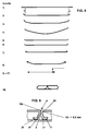
- the reduced sheet metal thickness is produced by rolling in the longitudinal direction of the aluminum sheet metal strip in a first processing step, the sheet metal thickness of the sheet metal strip being reduced by approximately 30% in the region of the bending radii 12 . This process step takes place before the production of the bending radii 12 , ie the rollers act on the flat sheet metal strip to reduce the sheet thickness. This was indicated by step 1 in FIG. 5. In principle, 8 out of a total of 18 possible steps were drawn there.
- step 4 the sheet metal strip was cambered in order to achieve a certain pretension of the sheet metal strip, which is intended to prevent the broad side of the heat exchanger tube from collapsing.
- step 2 it is possible to start with the step designated there as step 2 and at the same time to reduce the sheet thickness with the production of the bending radii 12 .
- rollerers this means a manufacturing process that is carried out with a system known per se. Forming operations on the endless sheet metal strip take place in succession on the system, with a plurality of pairs of rollers interacting. Each pair of rollers consists of a roller arranged above and below the sheet metal strip. The finished heat exchanger tube is cut to the appropriate length after leaving the system.
- the sheet thickness in the region of the bending radii 12 is, for example, 0.20 mm, as was shown in FIG. 2.
- the sheet metal strip has a thickness of approximately 0.30 mm.
- the part of the distance a between one broad side 1 and the other broad side 2 , in which the legs 10, 11 abut one another, begins at the foot 13 of the legs 10, 11 or in the bending radii 12.
- the legs 10, 11 have been bent to an angle of approximately 60 °, ie they have a further bend 30 .
- This bend 30 forms the point in which the legs 10, 11 can be further spread under load in the direction perpendicular to the broad sides 1, 2 , or where they give in and thus allow tolerance compensation, without the connection 5 to affect.
- This bend 30 does not have to be reduced in the sheet thickness, since it does not extend into the outside of the heat exchanger tube or because the radius in this bend 30 does not have to have a certain small value. It can be seen from FIG. 2 that an isosceles triangle is formed between the legs 10, 11 and the other broad side 2 .
- the head 14 of the legs 10, 11 forming the end of the respective leg 10, 11 is bent in the direction of the respective longitudinal edge 20, 21 belonging to the narrow side 3, 4 of the heat exchanger tube and is supported with the bent end on the other broad side.
- the sheet thickness in the area of the bending radii 12 is first reduced by means of rollers before the bending radii 12 are produced themselves.
- the longitudinal edges 20 , 21 of the sheet metal strip are connected to one another in a narrow side 3 of the heat exchanger tube, in such a way that both longitudinal edges 20, 21 are deformed approximately semicircular in cross section.
- One longitudinal edge 21 has a larger semicircle and the other longitudinal edge 20 has a smaller semicircle, so that the smaller semicircle fits into the larger semicircle and can be soldered therein.
- the longitudinal edge 20 with the smaller semicircle has a bend 31 towards the inside of the tube. The size of the bend 31 corresponds approximately to the sheet metal strip thickness.
- a smaller sheet thickness is present in the bending radius 12 of this bend 31 than in the adjacent sections of the longitudinal edge 20 of the sheet metal strip.
- This bend 31 can also be produced in such a way that the sheet thickness in the bending radius 12 is first reduced and then the bend 31 is produced itself. As can be seen from FIG. 3, this leads to the size of the “free cut” on the outside of the heat exchanger tube being minimized where the two longitudinal edges 20, 21 meet. Such small paragraphs, which present themselves as "holes”, can easily be sealed when the ends of the heat exchanger tubes are soldered into openings in tube sheets.
- the case shown has a connection 5 which, as already mentioned, is formed from the broad side 1 of the heat exchanger tube.
- the sheet thickness was also reduced in the two bending radii 12 there in the first manufacturing step before the bending radii 12 were produced in-house.
- connection 5 according to the invention from FIGS. 1 and 2 constructed from two longitudinal edges 20, 21 and further connections 5 (folds 50 ) from FIGS. 3 and 4 with one another.
- Such tubes then have more than two chambers 6, 7 and are preferably produced from a sheet metal strip soldered on both sides in order to be able to solder the connection 5 (fold 50 ) shown in FIGS. 3 and 4 on the opposite broad side 2.
- FIG. 1 only two folds 50 have been indicated by way of example in order to illustrate the possibility described above.
- connection 5 of a heat exchanger tube was shown, the sheet thickness in the bending radii 12 was not reduced. There, an inner bending radius of less than 0.2 mm was produced by means of rollers, the aluminum being displaced or displaced in the direction of the outer bending radius 12a , which is thereby made very small.
- the second bend 30 was provided in the legs 10, 11 , which is important for the tolerance compensation and for the elasticity of the connection 5 .
- the end of the longitudinal edge 20 or 21 is deformed approximately semicircular, which supports the tolerance compensation.
Landscapes
- Engineering & Computer Science (AREA)
- Physics & Mathematics (AREA)
- Thermal Sciences (AREA)
- Mechanical Engineering (AREA)
- General Engineering & Computer Science (AREA)
- Geometry (AREA)
- Bending Of Plates, Rods, And Pipes (AREA)
- Heat-Exchange Devices With Radiators And Conduit Assemblies (AREA)
Abstract
Description
Ferner betrifft die Erfindung ein Herstellungsverfahren für das Wärmetauscherrohr. Flache Wärmetauscherrohre mit den vorstehenden Merkmalen sind aus der US 6, 209, 202 B1 und aus einer ganzen Reihe weiterer Dokumente bekannt, da es sich um ein äußerst intensiv bearbeitetes Gebiet der Technik handelt. In diesem Dokument sind ganz geringe Biegeradien am Fuß der Schenkel vorgesehen. Enge Biegeradien bewirken, dass die eng aneinander liegenden Schenkel zum äußeren Umfang des Wärmetauscherrohres hin, dort, wo das Wärmetauscherrohr später in Öffnungen von Rohrböden verlötet wird, nur ein sehr kleines etwa dreieckförmiges "Loch" belassen, das ohne Probleme beim Löten verschlossen wird. In der US 5, 934, 365 wurden sogar ganz bestimmte kleine Durchmesser für einen in das "Loch" passenden Kreis beansprucht. In der US - Schrift 5, 890 288 werden die geringen Biegeradien dadurch erreicht, dass mit einem Werkzeug auf die umgeformten Längsränder eine senkrechte Kraft aufgetragen wird. Das ist dort in Fig. 7 gezeigt worden. Obwohl die beschriebenen bekannten Lösungen auf die Lösung eines lange bestehenden Problems zielen, sind sie nicht ohne Nachteile. Beispielsweise muss die Umformung des Randes in bestimmten engen Toleranzen erfolgen, weshalb sehr viel Wert auf die ständige Kontrolle des Zustandes der Werkzeuge (Walzen) und auf die Instandhaltung derselben gelegt werden muss. Es wäre hier wünschenswert, die zulässigen Toleranzen etwas größer gestalten zu können, bzw. das Wärmetauscherrohr so auszubilden, dass etwas größere Toleranzen noch akzeptabel sind und somit der Kontroll - und Instandhaltungsaufwand etwas reduziert werden kann.
Um möglichst enge Biegeradien zu realisieren, ist es für mit Ziehwerkzeugen hergestellte Wärmetauscherplatten bekannt, die Wärmetauscherplatten, angrenzend an den Biegeradius, in ihrer Blechdicke zu reduzieren. (Siehe EP 742 418 B1, Fig. 2) Es sind jedoch eine Reihe von erfinderischen Überlegungen anzustellen, um diesen bekannten Gedanken auf mittels Walzen aus einem Blechstreifen hergestellte Wärmetauscherrohre zu übertragen, denn die flachen Wärmetauscherrohre sind in ihrem kleinen Durchmesser oftmals nicht breiter als 2,0 mm und die verwendeten Blechdicken liegen im 10tel Millimeterbereich.
Ein erfindungsgemäßes Herstellungsverfahren für das flache Wärmetauscherrohr, sieht vor, dass vor oder gleichzeitig mit der Herstellung der Biegeradien die Blechdicke des Blechbandes im Bereich der Biegeradien um bis zu 40% mittels Walzen reduziert wird.
Ein anderes Herstellungsverfahren sieht vor, den inneren Biegeradius auf weniger als 0,2 mm auszuwalzen und dabei das Material in Richtung auf den äußeren Biegeradius zu verschieben bzw. zu verdrängen, der dadurch minimiert wird.
Dadurch, dass die Blechdicke der Schenkel im Bereich des Biegeradius kleiner ist als in den übrigen Abschnitten der Schenkel, so dass der Verbindungssteg an den Füßen seine kleinste Dicke besitzt, wobei die reduzierte Blechdicke durch profilierte Walzen herstellbar ist, die von der späteren Innenseite des Wärmetauscherrohres aus in den Biegeradius hinein wirken, sind solch kleine Biegeradien möglich, dass das spätere Dichtlöten der Rohrenden in den Öffnungen von Rohrböden problemlos möglich ist.
Die Blechdicke in den Biegeradien ist um maximal 40% der Blechdicke des Blechbandes reduziert worden, was sich als vorteilhaft herausgestellt hat. Größere Reduzierungen beeinträchtigen die Festigkeit des Rohres.
Die Schenkel bilden zwischen sich und der anderen Breitseite in einigen Ausführungsbeispielen etwa ein gleichschenkliges Dreieck.
Der Winkel von >20 °, bevorzugt von 60°, zwischen den Schenkeln erlaubt es, etwas größere Toleranzen bei so ausgebildeten Wärmetauscherrohren zuzulassen. Die aus dem Blechband hergestellten Wärmetauscherrohre werden je nach Anwendungsfall in entsprechende Gebrauchslängen geschnitten und gemeinsam mit Wellrippen zum sogenannten Rippen - Rohr - Block oder zum Netz des Wärmetauschers gestapelt. Das Netz wird gelötet, wobei es mit Gewichten belastet wird, um das gesamte Netz bis zur Beendigung des Lötprozesses unter einer gewissen Spannung zu halten und somit qualitätsgerechte Wärmetauschernetze herstellen zu können. Es scheint nachvollziehbar zu sein, dass eine senkrecht zu den Breitseiten wirkende Kraft, die durch das Gewicht erzeugt wird, die Schenkel, falls sie etwas zu lang sein sollten, soweit aufbiegen wird, bis die Breitseite eben ist. Abgerundete Enden der aus den Längsrändern des Blechbandes hergestellten Schenkel unterstützen diese Wirkung. Sollten die Schenkel etwas zu kurz sein, wird das Gewicht die Breitseiten soweit zusammendrücken, dass die Enden der Schenkel an der gegenüberliegenden Breitseite trotzdem verlötet werden können. Es sollte jedoch darauf geachtet werden, dass die Breitseiten nicht zu stark einfallen. Insofern sind Plustoleranzen leichter kompensierbar als Minustoleranzen.
Das den Kopf der Schenkel bildende Ende des jeweiligen Schenkels ist in Richtung auf die zum jeweiligen Längsrand gehörende Schmalseite des Wärmetauscherrohres hinweisend abgebogen und mit dem abgebogenen Ende an der anderen Breitseite abgestützt. Auch diese Maßnahme ist hinsichtlich größerer Toleranzen hilfreich, da Toleranzen in der Breite des Blechbandes mit diesen erwähnten Enden ausgleichbar sind.
Wenigstens eine Seite des Blechbandes ist lotplattiert, nämlich die spätere Außenseite des Wärmetauscherrohres. Bestimmte Ausführungen können beidseitig lotplattierte Blechbänder benötigen, wenn beispielsweise weitere bekannte aus einer einzigen Breitseite geformte Verbindungen zwischen den Breitseiten zur Unterteilung des Wärmetauscherrohres in mehr als zwei Kammern vorgesehen werden sollten. Solche Verbindungen können auch abwechselnd, d. h., mal aus der einen Breitseite und mal aus der anderen Breitseite, geschaffen werden.
- Fig. 1
- Querschnitt durch ein bevorzugtes erfindungsgemäßes Wärmetauscherrohr;
- Fig. 2
- Vergrößerter Ausschnitt aus Fig. 1;
- Fig. 3
- Schnitt durch ein anderes Wärmetauscherrohr;
- Fig. 4
- Vergrößerter Ausschnitt aus Fig. 3;
- Fig. 5
- Fertigungsschritte;
- Fig. 6
- Vergrößerter Ausschnitt aus einem Wärmetauscherrohr;
Die Blechdicke der Schenkel 10, 11 ist im Bereich der Biegeradien 12 kleiner als in den übrigen Abschnitten der Schenkel 10, 11, so dass die Verbindung 5 an den Füßen 13 ihre kleinste Blechdicke besitzt. Die reduzierte Blechdicke wird durch Walzen in Längsrichtung des Aluminium - Blechbandes in einem ersten Bearbeitungsschritt hergestellt, wobei die Blechdicke des Blechbandes im Bereich der Biegeradien 12 um etwa 30% reduziert wird. Dieser Verfahrensschritt läuft vor der Herstellung der Biegeradien 12 ab, d. h. die Walzen wirken zur Reduzierung der Blechdicke auf das flache Blechband ein. Dies wurde in der Fig. 5 durch den Schritt 1 angedeutet. Dort sind 8 von insgesamt 18 möglichen Schritten rein prinzipiell gezeichnet worden. Im Schritt 4 wurde eine Bombierung des Blechbandes vorgenommen, um eine gewisse Vorspannung des Blechstreifens zu erreichen, die das Einfallen der Breitseite des Wärmetauscherrohres verhindern soll. Möglich ist es jedoch, mit dem dort als Schritt 2 bezeichneten Schritt zu beginnen und gleichzeitig mit der Herstellung der Biegeradien 12 die Reduzierung der Blechdicke vorzunehmen. Wenn hier von "Walzen" die Rede ist, ist darunter ein Herstellungsverfahren zu verstehen, das mit einer an sich bekannten Anlage durchgeführt wird. Auf der Anlage laufen Umformoperationen am endlosen Blechband nacheinander ab, wobei eine Mehrzahl von Walzenpaaren zusammenwirken. Jedes Walzenpaar besteht aus einer oberhalb und einer unterhalb des Blechbandes angeordneten Walze. Das fertige Wärmetauscherrohr wird nach dem Verlassen der Anlage auf entsprechende Gebrauchslängen zugeschnitten. Im Ausführungsbeispiel beträgt die Blechdicke im Bereich der Biegeradien 12 beispielsweise noch 0,20 mm, wie es in der Fig. 2 eingezeichnet wurde. Das Blechband hat etwa eine Dicke von 0, 30 mm.
Der Teil des Abstandes a zwischen der einen Breitseite 1 und der anderen Breitseite 2, in dem die Schenkel 10, 11 aneinander anliegen, beginnt am Fuß 13 der Schenkel 10, 11, bzw. in den Biegeradien 12. Danach sind die Schenkel 10, 11 auf einen Winkel von etwa 60° abgebogen worden, d. h. sie weisen ein weitere Abbiegung 30 auf. Diese Abbiegung 30 bildet diejenige Stelle, in der sich die Schenkel 10, 11 bei Belastung in Richtung senkrecht zu den Breitseiten 1, 2 weiter spreizen lassen, bzw., wo sie nachgeben werden und somit den Toleranzausgleich erlauben, und zwar ohne dabei die Verbindung 5 zu beeinträchtigen. Diese Abbiegung 30 muss in der Blechdicke nicht reduziert werden, da sie nicht bis in die Außenseite des Wärmetauscherrohres hineinreicht bzw. weil der Radius in dieser Abbiegung 30 nicht einen bestimmten kleinen Wert haben muss.
Aus der Fig. 2 ist zu sehen, dass zwischen den Schenkeln 10, 11 und der anderen Breitseite 2 etwa ein gleichschenkliges Dreieck gebildet ist.
Das den Kopf 14 der Schenkel 10, 11 bildende Ende des jeweiligen Schenkels 10, 11 ist in Richtung auf die zum jeweiligen Längsrand 20, 21 gehörende Schmalseite 3, 4 des Wärmetauscherrohres abgebogen und mit dem abgebogenen Ende an der anderen Breitseite 2 abgestützt. Dieses Ende ist etwas abgerundet, wodurch sich einerseits eine genügend große Lötverbindungsfläche zwischen den Längsrändern 20, 21 und der Breitseite 2 ergibt und andererseits bewirkt die Rundung, dass sich der Winkel zwischen den Schenkeln 10, 11 leichter aufspreizen lässt, was dem Toleranzausgleich dient. In diesem Ausführungsbeispiel ist die Außenseite des Wärmetauscherrohres lotplattiert.
Die Fig. 3 und 4 zeigen einen Fall, in dem die zwei Schenkel 10, 11 einer anderen Verbindung 5 aus einer Breitseite 1 in der Art einer Faltung 50 geformt sind. Solche Faltungen 50 sind in dem beschriebenen erfindungsgemäßen Wärmetauscherrohr vorsehbar. Die Schenkel 10, 11 liegen über den gesamten Abstand a zwischen der einen Breitseite 1 und der anderen Breitseite 2 aneinander an. Am Kopf 14 sind die Schenkel 10, 11 miteinander verbunden.
Hier wird zunächst die Blechdicke im Bereich der Biegeradien 12 mittels Walzen reduziert, bevor die Biegeradien 12 selbst hergestellt werden. Die Längsränder 20, 21 des Blechbandes sind in einer Schmalseite 3 des Wärmetauscherrohres miteinander verbunden, derart, dass beide Längsränder 20, 21 im Querschnitt gesehen etwa halbrund verformt sind. Der eine Längsrand 21 weist ein größeres Halbrund auf und der andere Längsrand 20 ein kleineres Halbrund, so dass das kleinere Halbrund in das größere Halbrund hinein passt und darin verlötet werden kann. Der Längsrand 20 mit dem kleineren Halbrund besitzt eine Abbiegung 31 zum Rohrinneren hin. Die Größe der Abbiegung 31 entspricht etwa der Blechbanddicke. Im Biegeradius 12 dieser Abbiegung 31 ist eine geringere Blechdicke vorhanden als in den angrenzenden Abschnitten des Längsrandes 20 des Blechbandes. Auch diese Abbiegung 31 kann dermaßen hergestellt werden, dass zunächst die Blechdicke im Biegeradius 12 reduziert und danach die Abbiegung 31 selbst hergestellt wird. Dies führt dazu, wie aus der Fig. 3 zu sehen ist, dass die Größe des "Freischnittes" an der Außenseite des Wärmetauscherrohres, dort, wo sich die beiden Längsränder 20, 21 treffen minimiert wird. Solche geringen sich als "Löcher" darstellenden Absätze sind ohne weiteres beim Löten der Enden der Wärmetauscherrohre in Öffnungen von Rohrböden abdichtbar. Der gezeigte Fall weist eine Verbindung 5 auf, die, wie bereits erwähnt, aus der Breitseite 1 des Wärmetauscherrohres geformt ist. Um zur Außenseite des Wärmetauscherrohres hin eine relativ kleine, durch Löten mit einem Rohrboden, leicht abdichtbare, Öffnung zu schaffen, wurde auch in den beiden dortigen Biegeradien 12 im ersten Herstellungsschritt die Blechdicke reduziert, bevor die Biegeradien 12 selbst hergestellt wurden.
In der Fig. 6 wurde die Verbindung 5 eines Wärmetauscherrohres gezeigt, deren Blechdicke in den Biegeradien 12 nicht reduziert wurde. Dort wurde mittels Walzen ein innerer Biegeradius von kleiner als 0,2 mm hergestellt, wobei das Aluminium in Richtung auf den äußeren Biegeradius 12a verschoben oder verdrängt wurde, der dadurch sehr klein ausgebildet ist. Auch in diesem Ausführungsbeispiel wurde die zweite Abbiegung 30 in den Schenkeln 10, 11 vorgesehen, die für den Toleranzausgleich und für die Elastizität der Verbindung 5 von Bedeutung ist. Das Ende des Längsrands 20 bzw. 21 ist etwa halbrund verformt, wodurch der Toleranzausgleich unterstützt wird.
Claims (10)
- Flaches Wärmetauscherrohr, das aus einem einzigen endlosen Blechstreifen geringer Blechdicke aus Aluminium mittels Walzen herstellbar ist, mit zwei mit einem Abstand (a) gegenüberliegenden Breitseiten (1, 2) und zwei gegenüberliegenden Schmalseiten (3, 4), sowie mit wenigstens einer Verbindung (5) zwischen den beiden Breitseiten (1, 2), um das Wärmetauscherrohr in wenigstens zwei Kammern (6, 7) aufzuteilen, wobei die Verbindung (5) aus zwei eng aneinander liegenden Schenkeln (10, 11) besteht, wobei die Schenkel (10, 11) einen mit einem geringen Biegeradius (12) in die Breitseite (1) übergehenden Fuß (13) und einen Kopf (14) aufweisen, der an der anderen Breitseite (2) anliegt und damit verlötbar ist, wobei die Schenkel (10, 11) aus den umgeformten zwei Längsrändern (20, 21) des Blechstreifens gebildet sind und zwischen sich einen Winkel einschließen,
dadurch gekennzeichnet, dass
die Schenkel (10, 11) nicht weiter als bis zur Hälfte des gesamten Abstandes (a) zwischen der einen Breitseite (1) und der anderen Breitseite (2) aneinander anliegen und dass eine weitere Abbiegung (30) der Schenkel (10, 11) vorgesehen ist, die so ausgebildet ist, dass der Winkel (a) zwischen den Schenkeln (10, 11) etwa > 20 °- 100° beträgt. - Flaches Wärmetauscherrohr nach Anspruch 1, dass der Winkel (α) vorzugsweise etwa 45° - 70° beträgt und die Schenkel (10, 11) zwischen sich und der anderen Breitseite ein gleichschenkliges Dreieck bilden.
- Flaches Wärmetauscherrohr nach Anspruch 1 oder 2, dadurch gekennzeichnet, dass der Teil des Abstandes (a) an dem die Schenkel (10, 11) aneinander anliegen besonders bevorzugt etwa 1/3 des Abstandes (a) zwischen den beiden Breitseiten (1, 2) beträgt.
- Flaches Wärmetauscherrohr nach den Ansprüchen 1, 2 oder 3, dadurch gekennzeichnet, dass das den Kopf (14) der Schenkel (10, 11) bildende Ende des jeweiligen Schenkels (10, 11) in Richtung auf die zum jeweiligen Längsrand (20, 21) gehörende Schmalseite (3, 4) des Wärmetauscherrohres abgebogen ist und mit dem abgebogenen Ende an der anderen Breitseite (2) abgestützt ist.
- Flaches Wärmetauscherrohr nach Anspruch 4, dadurch gekennzeichnet, dass das abgebogene Ende am Schenkel (10 oder 11) abgerundet ist.
- Flaches Wärmetauscherrohr nach einem der vorstehenden Ansprüche, dadurch gekennzeichnet, dass die Außenseite des Wärmetauscherrohres lotplattiert ist.
- Flaches Wärmetauscherrrohr nach einem der vorstehenden Ansprüche, dadurch gekennzeichnet, dass wenigstens eine oder mehrere weitere Verbindungen (5), die aus einer der Breitseiten (1 oder 2) gebildet sind, und eine Faltung (50) der Breitseite (1, 2) darstellen, in dem Wärmetauscherrohr vorgesehen sind, wobei bei mehreren solcher Faltungen (50) diese abwechselnd aus der einen Breitseite (1) und aus der anderen Breitseite (2) ausgebildet sein können.
- Verfahren zur Herstellung eines flachen Wärmetauscherrohres gemäß Anspruch 1 oder einem der anderen Ansprüche, dadurch gekennzeichnet, dass vor oder gleichzeitig mit der Herstellung der in die Außenseite des Wärmetauscherrohres hinein reichenden Biegeradien (12) die Blechdicke des Blechbandes im Bereich der Biegeradien (12) um bis zu 40% mittels Walzen reduziert wird.
- Verfahren nach Anspruch 7, dadurch gekennzeichnet, der innere Biegeradius (12i) etwa 0,2 mm beträgt.
- Verfahren zur Herstellung eines flachen Wärmetauscherrohres gemäß Anspruch 1 oder einem der anderen Ansprüche 2 - 7, dadurch gekennzeichnet, dass bei der Herstellung der Biegeradien (12) der innere Biegeradius (12i) auf einen Wert unterhalb von 0,2 mm gewalzt wird, wobei der äußere Biegeradius (12a) durch Verdrängung des Materials von innen nach außen minimiert wird.
Applications Claiming Priority (2)
| Application Number | Priority Date | Filing Date | Title |
|---|---|---|---|
| DE10328001 | 2003-06-21 | ||
| DE10328001A DE10328001A1 (de) | 2003-06-21 | 2003-06-21 | Flaches Wärmetauscherrohr |
Publications (2)
| Publication Number | Publication Date |
|---|---|
| EP1489372A1 true EP1489372A1 (de) | 2004-12-22 |
| EP1489372B1 EP1489372B1 (de) | 2016-04-13 |
Family
ID=33394925
Family Applications (1)
| Application Number | Title | Priority Date | Filing Date |
|---|---|---|---|
| EP04009052.4A Expired - Lifetime EP1489372B1 (de) | 2003-06-21 | 2004-04-16 | Flaches Wärmetauscherrohr |
Country Status (3)
| Country | Link |
|---|---|
| US (1) | US7665512B2 (de) |
| EP (1) | EP1489372B1 (de) |
| DE (1) | DE10328001A1 (de) |
Cited By (4)
| Publication number | Priority date | Publication date | Assignee | Title |
|---|---|---|---|---|
| DE102008051422A1 (de) * | 2008-10-11 | 2010-04-15 | Modine Manufacturing Co., Racine | Ganz-Metall-Wärmetauscher und Verfahren |
| WO2012007452A1 (de) * | 2010-07-16 | 2012-01-19 | Behr Gmbh & Co. Kg | Verlötbarer fluidkanal für einen wärmetauscher aus aluminium |
| US20180372412A1 (en) * | 2015-12-21 | 2018-12-27 | Mahle International Gmbh | Tube body and production method |
| DE102011076716B4 (de) | 2010-06-02 | 2021-09-30 | Denso Corporation | Drehwinkeldetektor |
Families Citing this family (27)
| Publication number | Priority date | Publication date | Assignee | Title |
|---|---|---|---|---|
| DE102004041101A1 (de) * | 2004-08-24 | 2006-03-02 | Behr Gmbh & Co. Kg | Flachrohr für einen Wärmeübertrager, insbesondere für Kraftfahrzeuge und Verfahren zur Herstellung eines Flachrohres |
| DE102005048227A1 (de) * | 2005-10-07 | 2007-04-12 | Behr Gmbh & Co. Kg | Heizkörper, Kühlkreislauf, Klimagerät für eine Kraftfahrzeug-Klimaanlage sowie Klimaanlage für ein Kraftfahrzeug |
| US8438728B2 (en) * | 2006-01-19 | 2013-05-14 | Modine Manufacturing Company | Flat tube, flat tube heat exchanger, and method of manufacturing same |
| US7921559B2 (en) * | 2006-01-19 | 2011-04-12 | Modine Manufacturing Company | Flat tube, flat tube heat exchanger, and method of manufacturing same |
| US20090014165A1 (en) * | 2006-01-19 | 2009-01-15 | Werner Zobel | Flat tube, flat tube heat exchanger, and method of manufacturing same |
| US8434227B2 (en) | 2006-01-19 | 2013-05-07 | Modine Manufacturing Company | Method of forming heat exchanger tubes |
| US20100288481A1 (en) * | 2006-01-19 | 2010-11-18 | Werner Zobel | Flat tube, flat tube heat exchanger, and method of manufacturing same |
| US8281489B2 (en) * | 2006-01-19 | 2012-10-09 | Modine Manufacturing Company | Flat tube, flat tube heat exchanger, and method of manufacturing same |
| US20090019696A1 (en) * | 2006-01-19 | 2009-01-22 | Werner Zobel | Flat tube, flat tube heat exchanger, and method of manufacturing same |
| US8191258B2 (en) * | 2006-01-19 | 2012-06-05 | Modine Manufacturing Company | Flat tube, flat tube heat exchanger, and method of manufacturing same |
| US8091621B2 (en) * | 2006-01-19 | 2012-01-10 | Modine Manufacturing Company | Flat tube, flat tube heat exchanger, and method of manufacturing same |
| US8683690B2 (en) * | 2006-01-19 | 2014-04-01 | Modine Manufacturing Company | Flat tube, flat tube heat exchanger, and method of manufacturing same |
| DE102006052581B4 (de) * | 2006-11-08 | 2024-06-13 | Innerio Heat Exchanger GmbH | Flaches Wärmetauscherrohr und Herstellungsverfahren |
| DE102007004993A1 (de) * | 2007-02-01 | 2008-08-07 | Modine Manufacturing Co., Racine | Herstellungsverfahren für Flachrohre und Walzenstraße |
| JP4297177B2 (ja) * | 2007-04-03 | 2009-07-15 | 株式会社デンソー | 熱交換器用チューブ |
| DE102007039292A1 (de) * | 2007-08-20 | 2009-02-26 | Behr Gmbh & Co. Kg | Mehrkammer-Flachrohr, Wärmetauscher und Verwendung eines Wärmetauschers |
| FR2923002B1 (fr) * | 2007-10-31 | 2015-12-11 | Valeo Systemes Thermiques | Tube pour echangeur thermique |
| DE102008007600A1 (de) * | 2008-02-04 | 2009-08-06 | Behr Gmbh & Co. Kg | Mehrkammer-Flachrohr, Wärmetauscher und Verwendung eines Wärmetauschers |
| DE102010023384B4 (de) | 2010-06-10 | 2014-08-28 | Modine Manufacturing Co. | Herstellungsverfahren, insbesondere für Rohre und Abreißvorrichtung |
| FR2962204B1 (fr) * | 2010-06-30 | 2014-11-21 | Valeo Systemes Thermiques | Tube d'echangeur de chaleur, echangeur de chaleur comportant de tels tubes et procede d'obtention d'un tel tube. |
| US9453599B2 (en) * | 2013-06-21 | 2016-09-27 | Ford Global Technologies, Llc | Bi-channel coolant tube having crossover channels to allow coolant interaction |
| AU2016362984B2 (en) * | 2015-12-01 | 2018-11-29 | Colgate-Palmolive Company | Oral care implement |
| US20200240715A1 (en) * | 2017-08-07 | 2020-07-30 | Modine Manufacturing Company | Heat exchanger tube |
| LU101492B1 (en) | 2019-11-25 | 2021-05-26 | Ht Holding Luxembourg S A | Flat heat exchanger tube |
| EP4273489B1 (de) * | 2022-05-03 | 2025-03-12 | Valeo Klimasysteme GmbH | Flachröhre für einen wärmetauscher |
| DE102023201550A1 (de) * | 2023-02-22 | 2024-08-22 | Mahle International Gmbh | Verfahren zur Herstellung eines gefalteten Flachrohrs |
| CN117722878A (zh) * | 2023-07-27 | 2024-03-19 | 杭州绿能新能源汽车部件有限公司 | 换热器 |
Citations (5)
| Publication number | Priority date | Publication date | Assignee | Title |
|---|---|---|---|---|
| US5579837A (en) * | 1995-11-15 | 1996-12-03 | Ford Motor Company | Heat exchanger tube and method of making the same |
| US5890288A (en) * | 1997-08-21 | 1999-04-06 | Ford Motor Company | Method for making a heat exchanger tube |
| US5934365A (en) * | 1997-08-21 | 1999-08-10 | Ford Motor Company | Heat exchanger |
| EP1074807A2 (de) * | 1999-08-02 | 2001-02-07 | Ford Motor Company | Gebogenes Rohr für Wärmetauscher und dessen Herstellung |
| JP2001170713A (ja) * | 1999-12-10 | 2001-06-26 | Karutekku:Kk | 管状体の製造方法及びロール成形機 |
Family Cites Families (12)
| Publication number | Priority date | Publication date | Assignee | Title |
|---|---|---|---|---|
| US2655181A (en) * | 1949-09-14 | 1953-10-13 | Mccord Corp | Tube construction |
| JPS5490750U (de) | 1977-12-12 | 1979-06-27 | ||
| DE3725602A1 (de) * | 1987-08-01 | 1989-02-09 | Sueddeutsche Kuehler Behr | Flachrohr fuer einen waermetauscher |
| US5186250A (en) * | 1990-05-11 | 1993-02-16 | Showa Aluminum Kabushiki Kaisha | Tube for heat exchangers and a method for manufacturing the tube |
| EP0742418B1 (de) | 1995-05-10 | 1998-12-09 | Längerer & Reich GmbH | Plattenwärmetauscher |
| GB2303089B (en) * | 1995-07-13 | 1998-04-15 | T & N Technology Ltd | Forming heat exchangers |
| US5956846A (en) * | 1997-03-21 | 1999-09-28 | Livernois Research & Development Co. | Method and apparatus for controlled atmosphere brazing of unwelded tubes |
| FR2787180B1 (fr) * | 1998-12-11 | 2001-03-02 | Valeo Thermique Moteur Sa | Tube plie pour echangeur de chaleur et procede pour sa conformation |
| GB2364770A (en) | 2000-07-11 | 2002-02-06 | Delphi Tech Inc | Heat exchanger and fluid pipe therefor |
| JP2002130969A (ja) | 2000-10-24 | 2002-05-09 | Japan Climate Systems Corp | 熱交換器用チューブ |
| US20040182559A1 (en) * | 2001-03-22 | 2004-09-23 | Kent Scott Edward | Heat exchanger tube |
| LU90919B1 (en) * | 2002-05-14 | 2003-11-17 | Delphi Tech Inc | Method and tool for folding a metal strip |
-
2003
- 2003-06-21 DE DE10328001A patent/DE10328001A1/de not_active Withdrawn
-
2004
- 2004-04-16 EP EP04009052.4A patent/EP1489372B1/de not_active Expired - Lifetime
- 2004-06-09 US US10/865,291 patent/US7665512B2/en not_active Expired - Lifetime
Patent Citations (5)
| Publication number | Priority date | Publication date | Assignee | Title |
|---|---|---|---|---|
| US5579837A (en) * | 1995-11-15 | 1996-12-03 | Ford Motor Company | Heat exchanger tube and method of making the same |
| US5890288A (en) * | 1997-08-21 | 1999-04-06 | Ford Motor Company | Method for making a heat exchanger tube |
| US5934365A (en) * | 1997-08-21 | 1999-08-10 | Ford Motor Company | Heat exchanger |
| EP1074807A2 (de) * | 1999-08-02 | 2001-02-07 | Ford Motor Company | Gebogenes Rohr für Wärmetauscher und dessen Herstellung |
| JP2001170713A (ja) * | 1999-12-10 | 2001-06-26 | Karutekku:Kk | 管状体の製造方法及びロール成形機 |
Cited By (6)
| Publication number | Priority date | Publication date | Assignee | Title |
|---|---|---|---|---|
| DE102008051422A1 (de) * | 2008-10-11 | 2010-04-15 | Modine Manufacturing Co., Racine | Ganz-Metall-Wärmetauscher und Verfahren |
| DE102011076716B4 (de) | 2010-06-02 | 2021-09-30 | Denso Corporation | Drehwinkeldetektor |
| WO2012007452A1 (de) * | 2010-07-16 | 2012-01-19 | Behr Gmbh & Co. Kg | Verlötbarer fluidkanal für einen wärmetauscher aus aluminium |
| US10222145B2 (en) | 2010-07-16 | 2019-03-05 | Mahle International Gmbh | Solderable fluid channel for a heat exchanger of aluminum |
| US20180372412A1 (en) * | 2015-12-21 | 2018-12-27 | Mahle International Gmbh | Tube body and production method |
| US10677530B2 (en) * | 2015-12-21 | 2020-06-09 | Mahle International Gmbh | Tube body and production method |
Also Published As
| Publication number | Publication date |
|---|---|
| EP1489372B1 (de) | 2016-04-13 |
| US20050006082A1 (en) | 2005-01-13 |
| US7665512B2 (en) | 2010-02-23 |
| DE10328001A1 (de) | 2005-01-05 |
Similar Documents
| Publication | Publication Date | Title |
|---|---|---|
| EP1489372B1 (de) | Flaches Wärmetauscherrohr | |
| EP0176729B1 (de) | Wärmetauscher sowie Verfahren und Vorrichtung zur Herstellung derselben | |
| DE69701076T2 (de) | Verfahren und Vorrichtung zum Formwalzen von flachen Rohren | |
| EP2117742A1 (de) | Herstellungsverfahren für flachrohre, walzenstrasse und wärmetauscher mit solchen flachrohren | |
| DE10112255B4 (de) | Röhrchen zur Verwendung in Wärmetauschern | |
| DE69102000T2 (de) | Rohr und Verfahren zur Herstellung. | |
| EP0387678A1 (de) | Wärmeaustauscher und Verfahren zur flüssigkeitsdichten Befestigung einer Bodenplatte an einem Wärmeaustauschernetz | |
| EP1468235B1 (de) | Geschweisstes mehrkammerrohr | |
| EP2250457B1 (de) | Plattenwärmetauscher, wärmetauscherplatte und verfahren zu deren herstellung | |
| EP0565813B1 (de) | Wärmeaustauscher | |
| DE102014108463B4 (de) | Wärmeübertragerrohr, Wärmeübertrager und Verfahren zur Herstellung eines Wärmeübertragerrohrs | |
| DE19548495A1 (de) | Wärmetauscherblock für Wärmetauscher für Kraftfahrzeuge und Verfahren zu dessen Herstellung | |
| DE29614186U1 (de) | Wärmetauscher, insbesondere Wäschetrocknerkondensator, und zu dessen Herstellung bestimmte Rohranordnung | |
| DE3834822A1 (de) | Waermetauscher | |
| EP2212039A1 (de) | Verfahren zum herstellen eines profils aus flachem metallband | |
| DE2803365A1 (de) | Verfahren und vorrichtung zur herstellung von mit querrippen versehenen rohren | |
| DE102006035210B4 (de) | Flaches Wärmetauscherrohr und Herstellungsverfahren | |
| DE102006029378A1 (de) | Flachrohr für Wärmetauscher und Herstellungsverfahren | |
| DE2154487A1 (de) | Wärmetauscher und Verfahren zur seiner Herstellung | |
| DE10040138C1 (de) | Heizkörper, insbesondere Radiator, und Verfahren zu dessen Herstellung | |
| EP0648985A2 (de) | Solarabsorber und Verfahren zu dessen Herstellung | |
| DE4015830C2 (de) | Wärmetauscher, insbesondere Wasser/Luft-Kühler | |
| DE102006040519B4 (de) | Verfahren zur Herstellung einer Stromschiene | |
| DE3904250C2 (de) | Flachrohr für Wärmeaustauscher | |
| EP0815972B1 (de) | Verfahren zur Herstellung von Flachrohren zur Bildung von Wärmeträgerpaneelen und Presse zur Durchführung des Verfahrens |
Legal Events
| Date | Code | Title | Description |
|---|---|---|---|
| PUAI | Public reference made under article 153(3) epc to a published international application that has entered the european phase |
Free format text: ORIGINAL CODE: 0009012 |
|
| AK | Designated contracting states |
Kind code of ref document: A1 Designated state(s): AT BE BG CH CY CZ DE DK EE ES FI FR GB GR HU IE IT LI LU MC NL PL PT RO SE SI SK TR |
|
| AX | Request for extension of the european patent |
Extension state: AL HR LT LV MK |
|
| 17P | Request for examination filed |
Effective date: 20050622 |
|
| AKX | Designation fees paid |
Designated state(s): DE ES FR GB IT SE |
|
| 17Q | First examination report despatched |
Effective date: 20100615 |
|
| REG | Reference to a national code |
Ref country code: DE Ref legal event code: R079 Ref document number: 502004015162 Country of ref document: DE Free format text: PREVIOUS MAIN CLASS: F28D0001030000 Ipc: F28F0001020000 |
|
| GRAP | Despatch of communication of intention to grant a patent |
Free format text: ORIGINAL CODE: EPIDOSNIGR1 |
|
| RIC1 | Information provided on ipc code assigned before grant |
Ipc: F28F 1/02 20060101AFI20150911BHEP Ipc: F28D 1/03 20060101ALI20150911BHEP |
|
| INTG | Intention to grant announced |
Effective date: 20151007 |
|
| GRAS | Grant fee paid |
Free format text: ORIGINAL CODE: EPIDOSNIGR3 |
|
| GRAA | (expected) grant |
Free format text: ORIGINAL CODE: 0009210 |
|
| AK | Designated contracting states |
Kind code of ref document: B1 Designated state(s): DE ES FR GB IT SE |
|
| REG | Reference to a national code |
Ref country code: GB Ref legal event code: FG4D Free format text: NOT ENGLISH |
|
| REG | Reference to a national code |
Ref country code: DE Ref legal event code: R096 Ref document number: 502004015162 Country of ref document: DE |
|
| REG | Reference to a national code |
Ref country code: DE Ref legal event code: R082 Ref document number: 502004015162 Country of ref document: DE Representative=s name: ROSER, RENE, DIPL.-CHEM. DR., DE Ref country code: DE Ref legal event code: R082 Ref document number: 502004015162 Country of ref document: DE Representative=s name: ROSER, RENE, DR., DE |
|
| PG25 | Lapsed in a contracting state [announced via postgrant information from national office to epo] |
Ref country code: SE Free format text: LAPSE BECAUSE OF FAILURE TO SUBMIT A TRANSLATION OF THE DESCRIPTION OR TO PAY THE FEE WITHIN THE PRESCRIBED TIME-LIMIT Effective date: 20160413 Ref country code: ES Free format text: LAPSE BECAUSE OF FAILURE TO SUBMIT A TRANSLATION OF THE DESCRIPTION OR TO PAY THE FEE WITHIN THE PRESCRIBED TIME-LIMIT Effective date: 20160413 |
|
| PG25 | Lapsed in a contracting state [announced via postgrant information from national office to epo] |
Ref country code: IT Free format text: LAPSE BECAUSE OF FAILURE TO SUBMIT A TRANSLATION OF THE DESCRIPTION OR TO PAY THE FEE WITHIN THE PRESCRIBED TIME-LIMIT Effective date: 20160413 |
|
| REG | Reference to a national code |
Ref country code: DE Ref legal event code: R026 Ref document number: 502004015162 Country of ref document: DE |
|
| PLBI | Opposition filed |
Free format text: ORIGINAL CODE: 0009260 |
|
| PLAX | Notice of opposition and request to file observation + time limit sent |
Free format text: ORIGINAL CODE: EPIDOSNOBS2 |
|
| 26 | Opposition filed |
Opponent name: VALEO SYSTEMES THERMIQUES Effective date: 20170113 |
|
| REG | Reference to a national code |
Ref country code: FR Ref legal event code: ST Effective date: 20170203 |
|
| GBPC | Gb: european patent ceased through non-payment of renewal fee |
Effective date: 20160713 |
|
| PG25 | Lapsed in a contracting state [announced via postgrant information from national office to epo] |
Ref country code: FR Free format text: LAPSE BECAUSE OF NON-PAYMENT OF DUE FEES Effective date: 20160613 |
|
| PG25 | Lapsed in a contracting state [announced via postgrant information from national office to epo] |
Ref country code: GB Free format text: LAPSE BECAUSE OF NON-PAYMENT OF DUE FEES Effective date: 20160713 |
|
| PLAF | Information modified related to communication of a notice of opposition and request to file observations + time limit |
Free format text: ORIGINAL CODE: EPIDOSCOBS2 |
|
| PLBB | Reply of patent proprietor to notice(s) of opposition received |
Free format text: ORIGINAL CODE: EPIDOSNOBS3 |
|
| REG | Reference to a national code |
Ref country code: DE Ref legal event code: R100 Ref document number: 502004015162 Country of ref document: DE |
|
| PLCK | Communication despatched that opposition was rejected |
Free format text: ORIGINAL CODE: EPIDOSNREJ1 |
|
| PLBN | Opposition rejected |
Free format text: ORIGINAL CODE: 0009273 |
|
| STAA | Information on the status of an ep patent application or granted ep patent |
Free format text: STATUS: OPPOSITION REJECTED |
|
| 27O | Opposition rejected |
Effective date: 20181203 |
|
| REG | Reference to a national code |
Ref country code: DE Ref legal event code: R082 Ref document number: 502004015162 Country of ref document: DE Representative=s name: TER MEER STEINMEISTER & PARTNER PATENTANWAELTE, DE |
|
| PGFP | Annual fee paid to national office [announced via postgrant information from national office to epo] |
Ref country code: DE Payment date: 20230430 Year of fee payment: 20 |
|
| REG | Reference to a national code |
Ref country code: DE Ref legal event code: R071 Ref document number: 502004015162 Country of ref document: DE |