EP1489268B1 - Walzenlagerträgeranordnung für einen Flugzeugmotor und mit einer solchen Anordnung ausgerüsteter Flugzeugmotor - Google Patents
Walzenlagerträgeranordnung für einen Flugzeugmotor und mit einer solchen Anordnung ausgerüsteter Flugzeugmotor Download PDFInfo
- Publication number
- EP1489268B1 EP1489268B1 EP04102800A EP04102800A EP1489268B1 EP 1489268 B1 EP1489268 B1 EP 1489268B1 EP 04102800 A EP04102800 A EP 04102800A EP 04102800 A EP04102800 A EP 04102800A EP 1489268 B1 EP1489268 B1 EP 1489268B1
- Authority
- EP
- European Patent Office
- Prior art keywords
- bearing
- arrangement
- per
- supports
- bearing supports
- Prior art date
- Legal status (The legal status is an assumption and is not a legal conclusion. Google has not performed a legal analysis and makes no representation as to the accuracy of the status listed.)
- Active
Links
Images


Classifications
-
- F—MECHANICAL ENGINEERING; LIGHTING; HEATING; WEAPONS; BLASTING
- F01—MACHINES OR ENGINES IN GENERAL; ENGINE PLANTS IN GENERAL; STEAM ENGINES
- F01D—NON-POSITIVE DISPLACEMENT MACHINES OR ENGINES, e.g. STEAM TURBINES
- F01D21/00—Shutting-down of machines or engines, e.g. in emergency; Regulating, controlling, or safety means not otherwise provided for
- F01D21/04—Shutting-down of machines or engines, e.g. in emergency; Regulating, controlling, or safety means not otherwise provided for responsive to undesired position of rotor relative to stator or to breaking-off of a part of the rotor, e.g. indicating such position
- F01D21/045—Shutting-down of machines or engines, e.g. in emergency; Regulating, controlling, or safety means not otherwise provided for responsive to undesired position of rotor relative to stator or to breaking-off of a part of the rotor, e.g. indicating such position special arrangements in stators or in rotors dealing with breaking-off of part of rotor
-
- F—MECHANICAL ENGINEERING; LIGHTING; HEATING; WEAPONS; BLASTING
- F01—MACHINES OR ENGINES IN GENERAL; ENGINE PLANTS IN GENERAL; STEAM ENGINES
- F01D—NON-POSITIVE DISPLACEMENT MACHINES OR ENGINES, e.g. STEAM TURBINES
- F01D21/00—Shutting-down of machines or engines, e.g. in emergency; Regulating, controlling, or safety means not otherwise provided for
- F01D21/04—Shutting-down of machines or engines, e.g. in emergency; Regulating, controlling, or safety means not otherwise provided for responsive to undesired position of rotor relative to stator or to breaking-off of a part of the rotor, e.g. indicating such position
-
- F—MECHANICAL ENGINEERING; LIGHTING; HEATING; WEAPONS; BLASTING
- F01—MACHINES OR ENGINES IN GENERAL; ENGINE PLANTS IN GENERAL; STEAM ENGINES
- F01D—NON-POSITIVE DISPLACEMENT MACHINES OR ENGINES, e.g. STEAM TURBINES
- F01D25/00—Component parts, details, or accessories, not provided for in, or of interest apart from, other groups
- F01D25/16—Arrangement of bearings; Supporting or mounting bearings in casings
-
- F—MECHANICAL ENGINEERING; LIGHTING; HEATING; WEAPONS; BLASTING
- F05—INDEXING SCHEMES RELATING TO ENGINES OR PUMPS IN VARIOUS SUBCLASSES OF CLASSES F01-F04
- F05B—INDEXING SCHEME RELATING TO WIND, SPRING, WEIGHT, INERTIA OR LIKE MOTORS, TO MACHINES OR ENGINES FOR LIQUIDS COVERED BY SUBCLASSES F03B, F03D AND F03G
- F05B2260/00—Function
- F05B2260/30—Retaining components in desired mutual position
- F05B2260/301—Retaining bolts or nuts
- F05B2260/3011—Retaining bolts or nuts of the frangible or shear type
-
- F—MECHANICAL ENGINEERING; LIGHTING; HEATING; WEAPONS; BLASTING
- F16—ENGINEERING ELEMENTS AND UNITS; GENERAL MEASURES FOR PRODUCING AND MAINTAINING EFFECTIVE FUNCTIONING OF MACHINES OR INSTALLATIONS; THERMAL INSULATION IN GENERAL
- F16C—SHAFTS; FLEXIBLE SHAFTS; ELEMENTS OR CRANKSHAFT MECHANISMS; ROTARY BODIES OTHER THAN GEARING ELEMENTS; BEARINGS
- F16C19/00—Bearings with rolling contact, for exclusively rotary movement
- F16C19/02—Bearings with rolling contact, for exclusively rotary movement with bearing balls essentially of the same size in one or more circular rows
- F16C19/04—Bearings with rolling contact, for exclusively rotary movement with bearing balls essentially of the same size in one or more circular rows for radial load mainly
- F16C19/06—Bearings with rolling contact, for exclusively rotary movement with bearing balls essentially of the same size in one or more circular rows for radial load mainly with a single row or balls
-
- F—MECHANICAL ENGINEERING; LIGHTING; HEATING; WEAPONS; BLASTING
- F16—ENGINEERING ELEMENTS AND UNITS; GENERAL MEASURES FOR PRODUCING AND MAINTAINING EFFECTIVE FUNCTIONING OF MACHINES OR INSTALLATIONS; THERMAL INSULATION IN GENERAL
- F16C—SHAFTS; FLEXIBLE SHAFTS; ELEMENTS OR CRANKSHAFT MECHANISMS; ROTARY BODIES OTHER THAN GEARING ELEMENTS; BEARINGS
- F16C2360/00—Engines or pumps
- F16C2360/23—Gas turbine engines
-
- F—MECHANICAL ENGINEERING; LIGHTING; HEATING; WEAPONS; BLASTING
- F16—ENGINEERING ELEMENTS AND UNITS; GENERAL MEASURES FOR PRODUCING AND MAINTAINING EFFECTIVE FUNCTIONING OF MACHINES OR INSTALLATIONS; THERMAL INSULATION IN GENERAL
- F16C—SHAFTS; FLEXIBLE SHAFTS; ELEMENTS OR CRANKSHAFT MECHANISMS; ROTARY BODIES OTHER THAN GEARING ELEMENTS; BEARINGS
- F16C27/00—Elastic or yielding bearings or bearing supports, for exclusively rotary movement
- F16C27/04—Ball or roller bearings, e.g. with resilient rolling bodies
-
- Y—GENERAL TAGGING OF NEW TECHNOLOGICAL DEVELOPMENTS; GENERAL TAGGING OF CROSS-SECTIONAL TECHNOLOGIES SPANNING OVER SEVERAL SECTIONS OF THE IPC; TECHNICAL SUBJECTS COVERED BY FORMER USPC CROSS-REFERENCE ART COLLECTIONS [XRACs] AND DIGESTS
- Y10—TECHNICAL SUBJECTS COVERED BY FORMER USPC
- Y10S—TECHNICAL SUBJECTS COVERED BY FORMER USPC CROSS-REFERENCE ART COLLECTIONS [XRACs] AND DIGESTS
- Y10S416/00—Fluid reaction surfaces, i.e. impellers
- Y10S416/50—Vibration damping features
Definitions
- the present invention relates to the technical field of aircraft engines.
- the invention more specifically relates to a bearing support arrangement for an aircraft engine rotating shaft, able to compensate for the adverse effects induced by the use of a decoupler system.
- a decoupler system when provided on an aircraft engine, is activated for example in the event of significant unbalance of the rotating shaft caused for example by a rupture of the fan blade following a bird ingestion.
- the invention also relates to an aircraft engine equipped with such an arrangement of bearing supports for rotating shaft.
- proximal an element that is close to the rotating shaft
- distal an element that is remote from the rotating shaft
- the document EP 0 814 236 discloses a bearing support arrangement for a rotating shaft carrying equipment at the front and extending back from the equipment.
- the document FR 2 115 316 describes an improvement in the assembly of the rotor shafts in a gas turbine engine.
- a first bearing supports the shaft in the vicinity of the rotor.
- a second bearing carries the shaft away from the rotor and a third bearing supports the shaft at another distance from the rotor.
- the first bearing is designed to allow the inversion of the rotor if it becomes unbalanced.
- the rotating shaft 110 to which fan blades 112 are connected is guided in rotation by a first bearing 120, also called bearing No. 1, and by a second bearing 150, also called bearing No. 2, in downstream of the first bearing 120.
- the free ends of the fan blades 112 arrive in the vicinity of a casing 114 surrounding the fan stage.
- the second bearing 150 is, in the example illustrated, a roller bearing connected to the structure of the turbojet engine by a second bearing support 152.
- the first bearing 120 is, in the example, a ball bearing 121 connected to the structure 116 of the aircraft engine by a first bearing support 122.
- the first bearing support 122 comprises a first element 124 and a second element 140 having different stiffnesses.
- the second element 140 (steep path of effort) has a higher stiffness than the first element 140 (flexible force path).
- the first element 124 comprises a first flexible frustoconical wall 126 extending at its end farthest from the first bearing 120 by a first distal flange 128 and extending, at its other end, axially by a member 132 enclosing the bearing 120 and radially towards the outside by a first proximal flange 130.
- the second element 140 has a second flexible frustoconical wall 142 extending at its end farthest from the first bearing 120 by a second distal flange 144, and extending to its second end. another end radially inwardly by a second proximal flange 146.
- the two distal flanges 128, 144 are fixed to each other and to the structure 116 by means of bolts 134.
- the two proximal flanges 130, 146 are fastened to one another by means of connecting elements, called fusible elements 136, which are capable of breaking by shear under the effect of a radial force greater than or equal to a predetermined value, said elements fuses that can be bolts.
- fusible elements 136 which are capable of breaking by shear under the effect of a radial force greater than or equal to a predetermined value, said elements fuses that can be bolts.
- the fuse zone that is to say the zone where the fuse elements act, is indicated by 138.
- the rotating shaft In normal operation of the motor, the rotating shaft is connected to the structure by the combination of the steep path of effort and the flexible path of effort of the first bearing support, the forces being transmitted mainly by the steep path of effort.
- the fusible elements give way.
- the steep path of effort is no longer implemented.
- the rupture of the fusible elements makes it possible to avoid a deterioration of the structure of the motor, by preventing unbalance loads from propagating from the shaft to the structure via the steep path of the first bearing support.
- the solution provided by the document EP 0 814 236 is compatible with an axial positioning of the bearing held by such a bearing support, after rupture of the fusible elements, that is to say when the engine operates in degraded mode. Said axial positioning is obtained by means of the flexible force path.
- a thrust bearing may be associated with the flexible force path, for example a ball bearing, to maintain the axial positioning of the shaft itself and resume the axial thrust to which the shaft is subjected.
- D1 represents the radial displacement of the rotating shaft 110, measured at the axial position of the second bearing 150.
- D2 represents the radial displacement of the rotating shaft 110, measured at the axial position of the first bearing 120.
- the object of the present invention is to propose a bearing support arrangement for an aircraft engine rotating shaft, which comprises a steep path of effort and a flexible force path compatible with the movements of the shaft after decoupling, and which are easy to implement.
- the invention relates to a bearing support arrangement for a rotating shaft of an aircraft engine, said rotating shaft carrying equipment at the front and extending backward from the equipment, said shaft being mounted on a first front bearing supported by a first bearing support and on a second rear bearing supported by a second bearing support, the first and the second bearing being connected to a motor stator structure by bearing supports of which at least one has N> 1 elements acting substantially in parallel to simultaneously connect the bearing to said structure, among which N-1 said N elements perform this connection via fusible means. That of the two bearing supports which comprises said N> 1 elements is the support of second bearing.
- the second bearing is a bearing with axial stopping effect.
- the first bearing is not a bearing with axial stopping effect.
- said second bearing support comprises two elements acting substantially in parallel and simultaneously connecting the bearing to said structure, said two elements having different stiffnesses and defining a stiff element and a flexible element, said stiff element performing said connection between said second bearing and said structure via fusible means.
- said stiff element has, in longitudinal section, a substantially rectilinear profile.
- said flexible element has, in longitudinal section, a profile having substantially a pin shape having one or more curvatures.
- said pin-shaped profile comprises two curvatures.
- said bearing support with N> 1 elements further comprises radial abutment means for limiting the radial displacement of the shaft after implementation of the fuse means.
- said bearing support with N> 1 elements further comprises damping means associated with the radial abutment means, after implementation of the fuse means.
- the arrangement of bearing supports according to the invention has the advantage of having a double force path on the support of second bearing rather than the first bearing bracket, which gives it a more compact and lighter configuration.
- the invention relates to an aircraft engine equipped with such an arrangement of bearing supports.
- the equipment is a motor blower comprising vanes carried by said rotating shaft.
- an aircraft engine part comprising a shaft 10 rotating about an axis of rotation 2.
- an equipment 12 such as for example fan blades, whose free ends arrive in the vicinity of a casing 14 surrounding the fan stage.
- the rotating shaft 10 is mounted on a first bearing 20 which is a roller bearing 21, and on a second bearing 50 which is a ball bearing 51.
- the aircraft engine comprises a stator structure 16 to which the first stage is connected. 20 and the second bearing 50 respectively by a first bearing support 22 and a second bearing support 52.
- the first bearing support 22 comprises a revolution wall 23 having in longitudinal section a substantially rectilinear profile. Said wall 23 is extended forward by a member 32 surrounding the first bearing 20. To the rear, said wall 23 is connected to the structure 16, via a conventional decoupler system, that is to say -I mean only one effort path. For this purpose, the wall 23 terminates in a flange 34 extending radially outwards. It is fixed to the structure 16 by means of fusible elements 36, the whole defining a fuse zone 38.
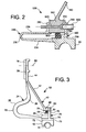
- the second bearing support 52 is illustrated in detail in FIGS. Figures 2 and 3 , which respectively represent two variants.
- the second bearing support 52 comprises a first element 24 and a second element 40 having different stiffnesses and constituting a dual force path.
- the second element 40 (steep path of effort) has a higher stiffness than the first element 24 (flexible force path).
- the second bearing support 52 also comprises a connecting ring 70 having a base 75 having an inner face 72 by which it engages the outer ring of the second bearing 50 and an outer face 74 opposite to the inner face 72, and a flange 76 extending radially outwardly.
- the first element 24 comprises a first flexible wall of revolution 26 having, in longitudinal section, a substantially pin-shaped profile.
- This first wall of revolution 26 extends at its end farthest from the second bearing 50 by a first distal flange 28 fixed to the structure 16 of the engine by any conventional means 60. It extends at its end closest to the second bearing 50 by a first proximal flange 30 which is oriented so as to be substantially parallel to the base 75.
- Said first proximal flange 30 is wedged, without being fixed, both against the outer face 74 of the base 75 and against the radial flange 76 of the connecting ring 70.
- the pin-shaped profile of the first wall of revolution 26 has, according to the first embodiment variant of the second bearing support 52 ( figure 3 ), the two curvatures 23, 25.
- the first proximal curvature 23 has a radius of curvature less than the radius of curvature of the distal curvature 25.
- the radii of curvature and the lengths of branches of the pin are chosen according to the desired flexibility properties for the flexible effort path.
- the curvatures 23, 25 constitute axial stop means which allow the flexible force path to take up the axial forces transmitted by the second bearing, and to limit the axial displacement of the rotating shaft forward when the fusible means (80, 800, 810) yielded, as will be explained below.
- the connecting ring 70 further comprises a protruding portion 78 extending from the radial flange 76 in a substantially axial direction, i.e. parallel to the base 75, on the side by which the two elements 40, 24 are fixed on said connecting ring 70.
- This projection portion 78 has the function of providing a radial abutment to limit the amplitude of the radial clearance D1 of the rotating shaft 10 when the fusible means 80 have yielded, as will be explained below.
- the second element 40 comprises a second flexible wall of revolution 42 having, in longitudinal section, a substantially rectilinear profile.
- This second wall of revolution 42 is extended at its end farthest from the second bearing 50 by a second distal flange 44 fixed to the structure 16 of the engine by any conventional means. It extends at its end closest to the second bearing 50 by a second proximal flange 46 fixed, by means of fusible means 80, to the free end of the radial collar 76 of the connecting ring 70.
- the second flange Proximal 46 is oriented so as to be substantially parallel to the base 75.
- the fusible means 80 which may be bolts, break under the effect of a shear stress.
- FIG. 5 is a schematic representation of the arrangement of bearing supports 20, 50, 22, 52, 520 according to the invention, similar to the arrangement of bearing supports 120, 150, 122, 152 of the prior art already described and shown schematically in the figure 4 .
- the second bearing 50 is connected to the structure 16 of the motor by the combination of the two elements 24 and 40, the forces being transmitted mainly by the steep path of forces, that is to say by the second element 40.
- the fusible means 36 located at the figure 5 in the fuse zone 38 of the first bearing support 22, yield.
- the fusible means 80 located in a fusible zone 82 of the support of the second bearing 52, in turn give way.
- the second bearing 50 is then no longer connected to the structure 16 by the flexible force path, that is to say by the first element 24 whose wall 26 has a substantially pin-shaped profile.
- the steep path of the second bearing support 52 that is to say the second element 40, is no longer implemented.
- the rotating shaft 10 then tends to move radially around the stable position that it occupies in normal operation, according to a radial clearance D1, D2.
- a radial clearance D1, D2 In practice, values of radial deflections of the order of 30 to 40 mm for D2 and of the order of 5 mm for D1 are encountered.
- the first element 24 makes it possible to axially retain the rotating shaft 10, without hindering its radial displacement.
- the proximal end of this first element 24, materialized by the first proximal flange 30, is moved in a substantially radial direction, said movement being limited by the projection portion 78, which plays, for this first proximal flange 30. , a radial abutment role against a proximal face 79 of the second proximal flange 46 of the second element 40.
- the spacing between said outer face 74 of the base 75 and said projection portion 78 is set according to the desired radial abutment effect.
- a damping means 90 shown schematically by a ring forming a damping cushion at the figure 3 , is associated with the projection portion 78 to dampen the abutment effect. It is disposed between said protrusion portion 78 and the second proximal flange 46 of the second member 40.
- the second bearing support 50 is connected to a part 160 integral with the structure 16 of the engine. It comprises a first element 240 constituting a flexible force path and a second element 400, integral with the second bearing 50 or rigidly fixed thereto, constituting a steep path of effort.
- the first element 240 (flexible force path) is in the form of a pin having, in this variant embodiment, a single curvature 230 whose concavity is oriented so as to substantially face the second element 400.
- the radius The curvature and length of the branches of the hairpin are chosen according to the flexibility properties desired for the flexible stress path.
- the first member 240 is attached directly to the second bearing 520 by the free end of the proximal leg 234 of the pin. It comprises, at the free end of the distal branch 236 of the pin a distal flange 280 extending in a substantially radial direction.
- the second member 400 (steep path) is substantially in the form of a flange 760 extending radially outwardly from the second bearing 50, said flange 760 having a base 750 having a face 780 oriented outward and substantially axial.
- Fusible means 800 for example bolts, together secure the piece 160 secured to the structure 16, the first element or flexible force path 240, and the second element or steep path 400. More specifically, these fusible means 800 pass successively the radial flange 760 of the second element 400, an end 162 of the workpiece 160, and the distal flange 280 of the first element 240.
- the fuse means 800 are designed to include a fuse portion 810, by which they fix the radial flange 760 and the end 162 of the piece 160, and a non-fuse portion 820, by which they fix the end 162 of the piece 160 and the distal flange 280.
- the fuse means 800 are substantially oriented in an axial direction, and yield, in their fuse part, by shear under the effect of an imbalance exceeding a predetermined threshold.
- the fuse means 800 comprise in the fuse portion 810 an arrangement for calibrating their breaking effect, which is, in the example shown, in the form of a specific internal bore 830.
- the fuse portion 810 of the fuse means 800 gives way, while their non-fuse portion 820 does not give way.
- a damping means 900 shown schematically by a ring forming a cushion cushion at the figure 2 , is associated with the base 750 to dampen the radial abutment effect. It is disposed between said base 750 and the end 162 of the part 160.
- the first variant embodiment of the second bearing support 52 has the advantage of providing a solution whose implementation is easy.
- the second embodiment variant of the second bearing support 520 has, moreover, the advantage of a compact design that gives it a small footprint and a lower weight.
- fusible means that bolts capable of breaking in shear.
- These fusible means could be, for example, rivets or shearable rods in shear or traction, or a piece capable of deforming or breaking by buckling under the action of a force exceeding a predetermined value.
- the second bearing could be replaced by another bearing providing the axial stop function, such as for example a tapered bearing, in place of the ball bearing.
- fusible fixing means 810 and non-fusible fixing means 820 which would be distinct from each other.
Claims (13)
- Anordnung von Lagerträgern (20, 50; 22, 52, 520) für die Drehwelle (10) eines Flugzeugmotors, wobei diese Drehwelle (10) vom eine Einrichtung (12) trägt und sich von dieser Einrichtung (12) aus nach hinten erstreckt, wobei diese Drehwelle (10) an einem ersten, vorderen Lager (20), das von einem Träger des ersten Lagers (22) gehalten wird, sowie an einem zweiten, hinteren Lager (50), das von einem Träger des zweiten Lagers (52, 520) gehalten wird, montiert ist, wobei das erste und das zweite Lager mit einem Statoraufbau (16) des Motors durch Lagerträger (22, 52, 520) verbunden sind, von denen wenigstens einer N>1 elastische Elemente (24, 240; 40, 400) aufweist, die im Wesentlichen parallel wirken, um dieses Lager (20, 50) gleichzeitig mit diesem Aufbau (16) zu verbinden, wobei davon N-1 dieser N elastischen Elemente (24, 240; 40, 400) diese Verbindung über Sicherungsmittel (80, 800, 810) herstellen,
dadurch gekennzeichnet,
dass derjenige der beiden Lagerträger (22, 52, 520), der diese N>1 elastischen Elemente (24, 240; 40, 400) aufweist, der Träger des zweiten Lagers (52, 520) ist. - Anordnung von Lagerträgern (20, 50; 22, 52, 520) nach Anspruch 1,
dadurch gekennzeichnet,
dass das zweite Lager (52, 520) ein Lager mit axialer Arretierwirkung ist. - Anordnung von Lagerträgern (20, 50; 22, 52, 520) nach Anspruch 2,
dadurch gekennzeichnet,
dass das zweite Lager (52, 520) ein Kugellager mit Kugeln (51) ist. - Anordnung von Lagerträgern (20, 50; 22, 52, 520) nach einem der Ansprüche 1 bis 3,
dadurch gekennzeichnet,
dass das erste Lager (20) ein Lager ohne axiale Arretierwirkung ist. - Anordnung von Lagerträgern (20, 50; 22, 52, 520) nach Anspruch 4,
dadurch gekennzeichnet,
dass das erste Lager (20) ein Rollenlager ist. - Anordnung von Lagerträgern (20, 50; 22, 52, 520) nach einem der Ansprüche 1 bis 5,
dadurch gekennzeichnet,
dass der genannte Träger des zweiten Lagers (52, 520) zwei Elemente (24, 240; 40, 400) aufweist, die im Wesentlichen parallel wirken und dieses zweite Lager (50) gleichzeitig mit dem Aufbau (16) verbinden, und dass diese beiden Elemente (24, 240; 40, 400) unterschiedliche Steifigkeiten aufweisen und ein steifes Element (40, 400) und ein biegsames Element (24, 240) bilden, wobei das steife Element (40, 400) diese Verbindung zwischen dem zweiten Lager (50) und diesem Aufbau (16) über Sicherungsmittel (80, 800, 810) herstellt. - Anordnung von Lagerträgern (20, 50; 22, 52, 520) nach Anspruch 6,
dadurch gekennzeichnet,
dass das steife Element (40, 400) im Längsschnitt ein im Wesentlichen geradliniges Profil aufweist. - Anordnung von Lagerträgern (20, 50; 22, 52, 520) nach Anspruch 6 oder 7,
dadurch gekennzeichnet,
dass das biegsame Element (24, 240) im Längsschnitt ein im Wesentlichen haamadeiförmiges Profil aufweist. - Anordnung von Lagerträgern (20, 50; 22, 52, 520) nach Anspruch 8,
dadurch gekennzeichnet,
dass dieses haarnadelförmige Profil mindestens eine Krümmung (23, 25) aufweist. - Anordnung von Lagerträgern (20, 50; 22, 52, 520) nach Anspruch 8 oder 9,
dadurch gekennzeichnet,
dass das biegsame Element (24, 240) Mittel zur axialen Arretierung (23, 25) umfasst, um die axialen Kräfte auszunehmen, die von dem zweiten Lager übertragen werden, nachdem die Sicherungsmittel (80, 800, 810) zum Einsatz gekommen sind. - Anordnung von Lagerträgern (20, 50; 22, 52, 520) nach einem der Ansprüche 1 bis 10,
dadurch gekennzeichnet,
dass der genannte Träger des zweiten Lagers (52, 520) mit N>1 Elementen ferner Mittel zum radialen Anschlag (78, 780) aufweist, um den radialen Ausschlag (D1, D2) der Drehwelle (10) zu begrenzen, nachdem die Sicherungsmittel (80, 800, 810) zum Einsatz gekommen sind. - Anordnung von Lagerträgern (20, 50; 22, 52, 520) nach Anspruch 11,
dadurch gekennzeichnet,
dass dieser Träger des zweiten Lagers (52, 520) mit N>1 Elementen ferner Dämpfungsmittel (90, 900) in Verbindung mit den Mitteln zum radialen Anschlag (78, 780) aufweist. - Flugzeugmotor,
dadurch gekennzeichnet,
dass es eine Anordnung von Lagerträgern (20, 50; 22, 52, 520) nach einem der Ansprüche 1 bis 12 aufweist.
Applications Claiming Priority (2)
| Application Number | Priority Date | Filing Date | Title |
|---|---|---|---|
| FR0350240A FR2856430B1 (fr) | 2003-06-20 | 2003-06-20 | Agencement de supports de paliers pour arbre tournant d'un moteur d'aeronef et moteur d'aeronef equipe d'un tel agencement |
| FR0350240 | 2003-06-20 |
Publications (2)
| Publication Number | Publication Date |
|---|---|
| EP1489268A1 EP1489268A1 (de) | 2004-12-22 |
| EP1489268B1 true EP1489268B1 (de) | 2009-12-09 |
Family
ID=33396883
Family Applications (1)
| Application Number | Title | Priority Date | Filing Date |
|---|---|---|---|
| EP04102800A Active EP1489268B1 (de) | 2003-06-20 | 2004-06-18 | Walzenlagerträgeranordnung für einen Flugzeugmotor und mit einer solchen Anordnung ausgerüsteter Flugzeugmotor |
Country Status (6)
| Country | Link |
|---|---|
| US (1) | US7448808B2 (de) |
| EP (1) | EP1489268B1 (de) |
| CA (1) | CA2471665C (de) |
| DE (1) | DE602004024475D1 (de) |
| FR (1) | FR2856430B1 (de) |
| RU (1) | RU2357120C2 (de) |
Cited By (2)
| Publication number | Priority date | Publication date | Assignee | Title |
|---|---|---|---|---|
| US10844745B2 (en) | 2019-03-29 | 2020-11-24 | Pratt & Whitney Canada Corp. | Bearing assembly |
| US11492926B2 (en) | 2020-12-17 | 2022-11-08 | Pratt & Whitney Canada Corp. | Bearing housing with slip joint |
Families Citing this family (22)
| Publication number | Priority date | Publication date | Assignee | Title |
|---|---|---|---|---|
| EP1649145B1 (de) * | 2003-07-29 | 2008-05-28 | Pratt & Whitney Canada Corp. | Turbofan-Triebwerksgehäuse, Turbofantriebwerk und entsprechendes Verfahren |
| US7625128B2 (en) | 2006-09-08 | 2009-12-01 | Pratt & Whitney Canada Corp. | Thrust bearing housing for a gas turbine engine |
| US8262353B2 (en) * | 2007-11-30 | 2012-09-11 | General Electric Company | Decoupler system for rotor assemblies |
| DE102009053000B4 (de) * | 2009-11-16 | 2014-01-02 | Rolls-Royce Deutschland Ltd & Co Kg | Fanrückhaltescheibe für ein Strahltriebwerk |
| US20120275921A1 (en) * | 2011-04-28 | 2012-11-01 | General Electric Company | Turbine engine and load reduction device thereof |
| US9133729B1 (en) * | 2011-06-08 | 2015-09-15 | United Technologies Corporation | Flexible support structure for a geared architecture gas turbine engine |
| US9169780B2 (en) | 2011-07-15 | 2015-10-27 | Pratt & Whitney Canada Corp. | Connection for generator in a gas turbine engine |
| US10145266B2 (en) | 2012-01-31 | 2018-12-04 | United Technologies Corporation | Gas turbine engine shaft bearing arrangement |
| US9777592B2 (en) | 2013-12-23 | 2017-10-03 | Pratt & Whitney Canada Corp. | Post FBO windmilling bumper |
| US9777596B2 (en) | 2013-12-23 | 2017-10-03 | Pratt & Whitney Canada Corp. | Double frangible bearing support |
| EP3054107B1 (de) | 2015-02-09 | 2017-12-06 | Rolls-Royce North American Technologies, Inc. | Turbinenanordnung mit einer sperreinrichtung des rotorsystems |
| CN107795384B (zh) * | 2016-08-31 | 2019-10-11 | 中国航发商用航空发动机有限责任公司 | 断开装置及航空发动机 |
| US10274017B2 (en) * | 2016-10-21 | 2019-04-30 | General Electric Company | Method and system for elastic bearing support |
| US11453487B2 (en) * | 2018-06-28 | 2022-09-27 | Sikorsky Aircraft Corporation | Redundant helicopter pitch change bearing |
| US11460037B2 (en) | 2019-03-29 | 2022-10-04 | Pratt & Whitney Canada Corp. | Bearing housing |
| CN110159661B (zh) * | 2019-04-16 | 2021-11-30 | 深圳市速腾聚创科技有限公司 | 机械式激光雷达的轴承预紧结构 |
| US11105223B2 (en) | 2019-08-08 | 2021-08-31 | General Electric Company | Shape memory alloy reinforced casing |
| US11420755B2 (en) | 2019-08-08 | 2022-08-23 | General Electric Company | Shape memory alloy isolator for a gas turbine engine |
| US10794222B1 (en) * | 2019-08-14 | 2020-10-06 | General Electric Company | Spring flower ring support assembly for a bearing |
| US11280219B2 (en) | 2019-11-27 | 2022-03-22 | General Electric Company | Rotor support structures for rotating drum rotors of gas turbine engines |
| US11274557B2 (en) | 2019-11-27 | 2022-03-15 | General Electric Company | Damper assemblies for rotating drum rotors of gas turbine engines |
| US11828235B2 (en) | 2020-12-08 | 2023-11-28 | General Electric Company | Gearbox for a gas turbine engine utilizing shape memory alloy dampers |
Family Cites Families (9)
| Publication number | Priority date | Publication date | Assignee | Title |
|---|---|---|---|---|
| GB1318629A (en) * | 1970-11-21 | 1973-05-31 | Secr Defence | Gas turbine engine |
| FR2749883B1 (fr) | 1996-06-13 | 1998-07-31 | Snecma | Procede et support de palier permettant de maintenir en fonctionnement un turbomoteur pour aeronef apres apparition d'un balourd accidentel sur un rotor |
| GB2322914B (en) * | 1997-03-05 | 2000-05-24 | Rolls Royce Plc | Ducted fan gas turbine engine |
| GB2326679B (en) * | 1997-06-25 | 2000-07-26 | Rolls Royce Plc | Ducted fan gas turbine engine |
| US5947782A (en) * | 1997-11-12 | 1999-09-07 | Siladke; E. Robert | Motorized tubular flotation apparatus |
| US6240719B1 (en) * | 1998-12-09 | 2001-06-05 | General Electric Company | Fan decoupler system for a gas turbine engine |
| US6312215B1 (en) * | 2000-02-15 | 2001-11-06 | United Technologies Corporation | Turbine engine windmilling brake |
| US6491497B1 (en) * | 2000-09-22 | 2002-12-10 | General Electric Company | Method and apparatus for supporting rotor assemblies during unbalances |
| FR2832195B1 (fr) * | 2001-10-31 | 2004-01-30 | Snecma Moteurs | Systeme decoupleur pour l'arbre d'une soufflante de turboreacteur |
-
2003
- 2003-06-20 FR FR0350240A patent/FR2856430B1/fr not_active Expired - Fee Related
-
2004
- 2004-06-18 RU RU2004118679/11A patent/RU2357120C2/ru active
- 2004-06-18 US US10/870,059 patent/US7448808B2/en active Active
- 2004-06-18 DE DE602004024475T patent/DE602004024475D1/de active Active
- 2004-06-18 CA CA2471665A patent/CA2471665C/en active Active
- 2004-06-18 EP EP04102800A patent/EP1489268B1/de active Active
Cited By (2)
| Publication number | Priority date | Publication date | Assignee | Title |
|---|---|---|---|---|
| US10844745B2 (en) | 2019-03-29 | 2020-11-24 | Pratt & Whitney Canada Corp. | Bearing assembly |
| US11492926B2 (en) | 2020-12-17 | 2022-11-08 | Pratt & Whitney Canada Corp. | Bearing housing with slip joint |
Also Published As
| Publication number | Publication date |
|---|---|
| CA2471665C (en) | 2012-03-06 |
| FR2856430B1 (fr) | 2005-09-23 |
| CA2471665A1 (en) | 2004-12-20 |
| RU2004118679A (ru) | 2006-01-10 |
| FR2856430A1 (fr) | 2004-12-24 |
| US20050129343A1 (en) | 2005-06-16 |
| EP1489268A1 (de) | 2004-12-22 |
| DE602004024475D1 (de) | 2010-01-21 |
| US7448808B2 (en) | 2008-11-11 |
| RU2357120C2 (ru) | 2009-05-27 |
Similar Documents
| Publication | Publication Date | Title |
|---|---|---|
| EP1489268B1 (de) | Walzenlagerträgeranordnung für einen Flugzeugmotor und mit einer solchen Anordnung ausgerüsteter Flugzeugmotor | |
| EP1564352B1 (de) | Lagerungsvorrichtung mit zwei Lagern für die Bläserwelle eines Turbostrahltriebwerks | |
| CA2607245C (fr) | Agencement de palier d'un arbre tournant et turboreacteur equipe d'un tel agencement | |
| EP1561907B1 (de) | Turbostrahltriebwerk mit doppeltgelagerter Gebläseantriebswelle | |
| CA2813569C (fr) | Boitier de liaison entre un arbre d'entrainement de soufflante de moteur et un palier de roulement | |
| EP1659266B1 (de) | Gemeinsame Entkopplungsvorrichtung für das erste und das zweite Lager der Antriebswelle einer Turbomaschine, und Verdichter und Turbomaschine mit einer solchen Vorrichtung | |
| EP1540143B1 (de) | Rotorneuzentrierung nach der entkupplung | |
| EP1439316B1 (de) | Halter für ein Verbindungsorgan und diesem enthaltendes Entkupplungssystem | |
| EP2075413B1 (de) | Vorrichtung zur Versteifung eines Stators einer Strömungsmaschine und deren Anwendung in Luftfahrzeugmotoren | |
| FR2930595A1 (fr) | Rotor de soufflante d'une turbomachine ou d'un moteur d'essai | |
| FR2888621A1 (fr) | Dispositif de retention d'un support de palier dans une turbomachine comportant un dispositif de decouplage | |
| CA2921900C (fr) | Suspension isostatique d'un turboreacteur par double support arriere | |
| EP1605139A1 (de) | Turbomaschine mit axialer Rückhalteeinrichtung für den Rotor | |
| FR2926791A1 (fr) | Entree d'air pour nacelle d'aeronef, et ensemble propulsif comprenant une telle entree d'air | |
| FR3026774A1 (fr) | Turbomachine comportant un dispositif de freinage du rotor de soufflante. | |
| FR2995283A1 (fr) | Ensemble de cable de largage de turbine a air dynamique | |
| FR2877398A1 (fr) | Moteur rotatif avec un palier d'arbre a deux raideurs | |
| FR3011291A1 (fr) | Turbomachine a accouplement torsible integre a au moins un arbre menant et/ou mene | |
| FR3006713A1 (fr) | Dispositif de decouplage pour turbomachine comportant une piece intermediaire | |
| FR2831624A1 (fr) | Systeme decoupleur pour l'arbre d'une soufflante de turboreacteur | |
| EP3728794B1 (de) | Dämpfervorrichtung | |
| FR2877994A1 (fr) | Support de palier, et moteur d'aeronef equipe d'un tel support de palier. | |
| FR3042215B1 (fr) | Structure pour turbomachine comportant des moyens de retention axiale de bague exterieure de palier de roulement | |
| FR3113094A1 (fr) | Dispositif de liaison comportant une liaison de type pivot glissant pour le raccordement d’un carter d’échappement et d’un cône d’éjection de gaz d’échappement d’un turboréacteur d’aéronef | |
| FR3071866A1 (fr) | Ensemble de suspension arriere d'une turbomachine |
Legal Events
| Date | Code | Title | Description |
|---|---|---|---|
| PUAI | Public reference made under article 153(3) epc to a published international application that has entered the european phase |
Free format text: ORIGINAL CODE: 0009012 |
|
| AK | Designated contracting states |
Kind code of ref document: A1 Designated state(s): AT BE BG CH CY CZ DE DK EE ES FI FR GB GR HU IE IT LI LU MC NL PL PT RO SE SI SK TR |
|
| AX | Request for extension of the european patent |
Extension state: AL HR LT LV MK |
|
| 17P | Request for examination filed |
Effective date: 20050606 |
|
| AKX | Designation fees paid |
Designated state(s): BE DE FR GB |
|
| RAP1 | Party data changed (applicant data changed or rights of an application transferred) |
Owner name: SNECMA |
|
| 17Q | First examination report despatched |
Effective date: 20071002 |
|
| GRAP | Despatch of communication of intention to grant a patent |
Free format text: ORIGINAL CODE: EPIDOSNIGR1 |
|
| GRAS | Grant fee paid |
Free format text: ORIGINAL CODE: EPIDOSNIGR3 |
|
| GRAA | (expected) grant |
Free format text: ORIGINAL CODE: 0009210 |
|
| AK | Designated contracting states |
Kind code of ref document: B1 Designated state(s): BE DE FR GB |
|
| REG | Reference to a national code |
Ref country code: GB Ref legal event code: FG4D Free format text: NOT ENGLISH |
|
| REF | Corresponds to: |
Ref document number: 602004024475 Country of ref document: DE Date of ref document: 20100121 Kind code of ref document: P |
|
| PLBE | No opposition filed within time limit |
Free format text: ORIGINAL CODE: 0009261 |
|
| STAA | Information on the status of an ep patent application or granted ep patent |
Free format text: STATUS: NO OPPOSITION FILED WITHIN TIME LIMIT |
|
| 26N | No opposition filed |
Effective date: 20100910 |
|
| REG | Reference to a national code |
Ref country code: FR Ref legal event code: PLFP Year of fee payment: 13 |
|
| REG | Reference to a national code |
Ref country code: FR Ref legal event code: PLFP Year of fee payment: 14 |
|
| REG | Reference to a national code |
Ref country code: FR Ref legal event code: CD Owner name: SAFRAN AIRCRAFT ENGINES, FR Effective date: 20170717 |
|
| REG | Reference to a national code |
Ref country code: FR Ref legal event code: PLFP Year of fee payment: 15 |
|
| PGFP | Annual fee paid to national office [announced via postgrant information from national office to epo] |
Ref country code: FR Payment date: 20230523 Year of fee payment: 20 Ref country code: DE Payment date: 20230523 Year of fee payment: 20 |
|
| PGFP | Annual fee paid to national office [announced via postgrant information from national office to epo] |
Ref country code: BE Payment date: 20230523 Year of fee payment: 20 |
|
| PGFP | Annual fee paid to national office [announced via postgrant information from national office to epo] |
Ref country code: GB Payment date: 20230523 Year of fee payment: 20 |