EP1489032A1 - Rubber member sticking device - Google Patents
Rubber member sticking device Download PDFInfo
- Publication number
- EP1489032A1 EP1489032A1 EP03743059A EP03743059A EP1489032A1 EP 1489032 A1 EP1489032 A1 EP 1489032A1 EP 03743059 A EP03743059 A EP 03743059A EP 03743059 A EP03743059 A EP 03743059A EP 1489032 A1 EP1489032 A1 EP 1489032A1
- Authority
- EP
- European Patent Office
- Prior art keywords
- sheet
- sheet material
- fitting surfaces
- unvulcanized rubber
- sticking device
- Prior art date
- Legal status (The legal status is an assumption and is not a legal conclusion. Google has not performed a legal analysis and makes no representation as to the accuracy of the status listed.)
- Granted
Links
Images





Classifications
-
- B—PERFORMING OPERATIONS; TRANSPORTING
- B29—WORKING OF PLASTICS; WORKING OF SUBSTANCES IN A PLASTIC STATE IN GENERAL
- B29D—PRODUCING PARTICULAR ARTICLES FROM PLASTICS OR FROM SUBSTANCES IN A PLASTIC STATE
- B29D30/00—Producing pneumatic or solid tyres or parts thereof
- B29D30/0061—Accessories, details or auxiliary operations not otherwise provided for
-
- B—PERFORMING OPERATIONS; TRANSPORTING
- B29—WORKING OF PLASTICS; WORKING OF SUBSTANCES IN A PLASTIC STATE IN GENERAL
- B29D—PRODUCING PARTICULAR ARTICLES FROM PLASTICS OR FROM SUBSTANCES IN A PLASTIC STATE
- B29D30/00—Producing pneumatic or solid tyres or parts thereof
- B29D30/06—Pneumatic tyres or parts thereof (e.g. produced by casting, moulding, compression moulding, injection moulding, centrifugal casting)
- B29D30/08—Building tyres
- B29D30/20—Building tyres by the flat-tyre method, i.e. building on cylindrical drums
- B29D30/30—Applying the layers; Guiding or stretching the layers during application
-
- B—PERFORMING OPERATIONS; TRANSPORTING
- B65—CONVEYING; PACKING; STORING; HANDLING THIN OR FILAMENTARY MATERIAL
- B65H—HANDLING THIN OR FILAMENTARY MATERIAL, e.g. SHEETS, WEBS, CABLES
- B65H29/00—Delivering or advancing articles from machines; Advancing articles to or into piles
- B65H29/54—Article strippers, e.g. for stripping from advancing elements
- B65H29/56—Article strippers, e.g. for stripping from advancing elements for stripping from elements or machines
-
- B—PERFORMING OPERATIONS; TRANSPORTING
- B65—CONVEYING; PACKING; STORING; HANDLING THIN OR FILAMENTARY MATERIAL
- B65H—HANDLING THIN OR FILAMENTARY MATERIAL, e.g. SHEETS, WEBS, CABLES
- B65H2801/00—Application field
- B65H2801/93—Tyres
-
- Y—GENERAL TAGGING OF NEW TECHNOLOGICAL DEVELOPMENTS; GENERAL TAGGING OF CROSS-SECTIONAL TECHNOLOGIES SPANNING OVER SEVERAL SECTIONS OF THE IPC; TECHNICAL SUBJECTS COVERED BY FORMER USPC CROSS-REFERENCE ART COLLECTIONS [XRACs] AND DIGESTS
- Y10—TECHNICAL SUBJECTS COVERED BY FORMER USPC
- Y10S—TECHNICAL SUBJECTS COVERED BY FORMER USPC CROSS-REFERENCE ART COLLECTIONS [XRACs] AND DIGESTS
- Y10S425/00—Plastic article or earthenware shaping or treating: apparatus
- Y10S425/014—Expansible and collapsible
-
- Y—GENERAL TAGGING OF NEW TECHNOLOGICAL DEVELOPMENTS; GENERAL TAGGING OF CROSS-SECTIONAL TECHNOLOGIES SPANNING OVER SEVERAL SECTIONS OF THE IPC; TECHNICAL SUBJECTS COVERED BY FORMER USPC CROSS-REFERENCE ART COLLECTIONS [XRACs] AND DIGESTS
- Y10—TECHNICAL SUBJECTS COVERED BY FORMER USPC
- Y10T—TECHNICAL SUBJECTS COVERED BY FORMER US CLASSIFICATION
- Y10T428/00—Stock material or miscellaneous articles
- Y10T428/24—Structurally defined web or sheet [e.g., overall dimension, etc.]
- Y10T428/24273—Structurally defined web or sheet [e.g., overall dimension, etc.] including aperture
- Y10T428/24322—Composite web or sheet
- Y10T428/24331—Composite web or sheet including nonapertured component
- Y10T428/24339—Keyed
Definitions
- the present invention relates to a rubber member sticking device.
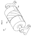
- a rubber member sticking device 100/106 in which a flat plate 104/cylindrical body 108 handles a viscous sheet material 102, is used as a device for holding and transferring a viscous sheet material such as an unvulcanized rubber sheet.
- a method is known wherein, when a viscous sheet material 102 is held by a rubber member sticking device 100/106, the viscous sheet material 102 is stuck on a flat plate 104/cylindrical body 108 which has a good adhesion compatibility with the viscous sheet material 102, and then, when the viscous sheet material 102 is transferred, force is applied thereon so that the viscous sheet material 102 is separated from the flat plate 104/cylindrical body 108.
- the viscous sheet material 102 may become deformed and stretch by virtue of a separation force.
- the present invention has been made in view of the above facts, and provides a rubber member sticking device which prevents the viscous sheet material from becoming deformed and stretching during the separation operation, suppresses loss of energy and eliminates traces of vacuum holes.
- a rubber member sticking device comprises: a first sheet receiving member including a separating surface capable of releasing from a sheet material; a second sheet receiving member including fitting surfaces capable of adhering to the sheet material; and a driving means driving the first sheet receiving member or the second sheet receiving member, such that, when the sheet material is stuck, the sheet material is supported by the separating surface and the fitting surfaces without a difference in level being created therebetween, and, when the sheet material is separated, the sheet material is supported only by the separating surface with a difference in level being created between the separating surface and the fitting surfaces; wherein the sheet material is a thin material and includes, for example, a viscous sheet material such as an unvulcanized rubber sheet material for tires.
- the sheet material when the sheet material is stuck, the sheet material is supported by the separating surface of the first sheet receiving member and the fitting surfaces of the second sheet receiving member without a difference in level being created therebetween. In this state, the sheet material is in close contact with the fitting surfaces of the second sheet receiving member.
- the driving means drives the first sheet receiving member or the second sheet receiving member to create a difference in level between the separating surface of the first sheet receiving member and the fitting surfaces of the second sheet receiving member so that the sheet material is supported only by the separating surface of the first sheet receiving member.
- the rubber member sticking device according to the present invention produces a superior effect insofar that the sheet material is prevented from becoming deformed and stretching during the separation operation, loss of energy is suppressed and traces of vacuum holes are eliminated.
- a surface constituted of the separating surface and the fitting surfaces, for supporting the sheet material is a flat surface.
- the sheet material is supported by the flat surface.
- the sheet material can be held even when the adhesive force on the fitting surfaces of the second sheet receiving member is relatively weak.
- the sheet material can be held and transferred with a modicum of energy.
- a surface constituted of the separating surface and the fitting surfaces, for supporting the sheet material is a cylindrical surface.
- the sheet material is supported by the cylindrical surface.
- the sheet material supported by the cylindrical surface is capable of rotating movement. A combination of the rotating movement and the separation operation enables the sheet material to be transferred easily.
- the sheet material is supported by a cylindrical body serving as a transfer drum for tires.
- the sheet material is supported by the cylindrical body serving as a transfer drum for tires, the sheet material can be transferred easily.
- An unvulcanized rubber sheet material for tires is preferably used as the sheet material.
- the separating surface of the first sheet receiving member is provided with a plurality of through-holes extending in a thickness direction of the first sheet receiving member, and the second sheet receiving member is provided so as to fit into/retract from the through-holes, so that the sheet material is supported by the fitting surfaces and the separating surface without a difference in level being created therebetween.
- the sheet material is supported by the separating surface of the first sheet receiving member and the fitting surfaces of the second sheet receiving member without a difference in level being created therebetween.
- the second sheet receiving member is pushed outside through the through-holes of the first sheet receiving member so as not to create a difference in level between the fitting surfaces of the second sheet receiving member and the separating surface of the first sheet receiving member.
- the second sheet receiving member is pulled inside through the through-holes of the first sheet receiving member, and the sheet material is supported only by the separating surface of the first sheet receiving member.
- This relatively simple structure in which the second sheet receiving member is provided so as to fit into/retract from the through-holes of the first sheet receiving member, provides the rubber member sticking device with plural surfaces to be fitted to the sheet material.
- the plural fitting surfaces where the sheet material and the second sheet receiving member make contact with each other, enable the sheet material to be held in a stable fashion. Further, since the force required to hold the sheet material is dispersed and thus only a relatively small force is applied to each of the fitting surfaces, only a relatively small force needs to be applied to each of the portions of the sheet material corresponding to the fitting surfaces during the separation operation. Accordingly, deformation and stretching of the sheet material during the separation operation can be prevented with greater certitude.
- the fitting surfaces are respectively formed in a substantially V-shape in a plan view.
- the sheet material makes contact with the substantially V-shaped fitting surfaces on the supporting surface.
- the fitting surfaces are respectively formed in a substantially V-shape and thus the fitting surfaces make close contact with the sheet material at a certain angle to the widthwise direction of the sheet material, the sheet material is easily separated from the fitting surfaces.
- the second sheet receiving member is provided at both end portions of the first sheet receiving member such that, when the sheet material is stuck, both end portions of the sheet material make contact with the fitting surfaces.
- both end portions of the sheet material make contact with the fitting surfaces of the second sheet receiving member.
- a rubber member sticking device 10 handles an unvulcanized rubber sheet 12 serving as a viscous sheet material.
- the unvulcanized rubber sheet 12 will now be outlined.
- rubber 90 in an unvulcanized state which is the raw material for the unvulcanized rubber sheet 12 (see Fig. 1), is softened by heat and supplied to an extruder 92.
- the extruder 92 extrudes the rubber 90 in the unvulcanized state from a mouthpiece 92A.
- the extruded rubber 90 in the unvulcanized state is cut into the unvulcanized rubber sheet 12.
- the unvulcanized rubber sheet 12 is held and transferred by the rubber member sticking device 10.
- the rubber member sticking device 10 includes a flat plate 14 serving as a first sheet receiving member, on which the unvulcanized rubber sheet 12 is disposed.
- the flat plate 14 may be made of a material capable of releasing from the unvulcanized rubber sheet 12 (e.g., Teflon®), or, alternatively, may be made of a material capable of adhering to the unvulcanized rubber sheet 12 (e.g., iron) and thereafter subjected to surface treatment (grain finish) so as to secure a release property. Since the unvulcanized rubber sheet 12 is supported by a separating surface 14A of the flat plate 14, the unvulcanized rubber sheet 12 can be separated by means of a modicum of force.
- the flat plate 14 is provided with plural rectangular through-holes 14B, which extend from the separating surface 14A in a thickness direction of the flat plate 14, and which are arranged in parallel with each other.
- a lifting member 16 serving as a second sheet receiving member is disposed below the through-holes 14B.
- the lifting member 16 is composed of a rectangular base plate 17 and fitting blocks 19 provided at predetermined intervals so as to protrude from an upper surface 17A of the base plate 17 and fit into the through-holes 14B.
- the height of the fitting blocks 19 is determined such that, when the fitting blocks 19 fit into the through-holes 14B, and in consequence there is no difference in level between fitting surfaces 19A of the fitting blocks 19 and the separating surface 14A and a flat surface is thereby formed, the upper surface 17A of the base plate 17 abuts against a bottom surface 14C of the flat plate 14.
- a capability of adhering to the unvulcanized rubber sheet 12 may be imparted to the fitting surfaces 19A by using a material capable of adhering to the unvulcanized rubber sheet 12 (e.g., iron) to make the fitting blocks 19 themselves, or alternatively, by subjecting the fitting blocks 19 to surface treatment.
- the base plate 17 is supported by a rod 18 of a hydraulic jack 20.
- the rod 18 is lengthened or shortened, the lifting member 16 is raised or lowered.
- the hydraulic jack 20 is contained in a casing 22.
- An opening 22A of the casing 22 is closed by the flat plate 14, and the lifting member 16 is accommodated inside the casing 22.
- guide blocks 24 are mounted on four corners of a bottom plate of the casing 22.
- Recessed portions 24A are respectively formed in lower surfaces of the guide blocks 24 to engage slidably with rails 26. This structure enables the casing 22 to move in the direction of Arrow A.
- the unvulcanized rubber sheet 12 when the unvulcanized rubber sheet 12 is stuck, the unvulcanized rubber sheet 12 is supported by the separating surface 14A of the flat plate 14 and the fitting surfaces 19A of the lifting member 16 without a difference in level being created therebetween. In this state, the unvulcanized rubber sheet 12 is in close contact with the fitting surfaces 19A of the lifting member 16. Since the gravity of the unvulcanized rubber sheet 12 acts directly on the fitting surfaces 19A, the unvulcanized rubber sheet 12 can be reliably held even when the adhesive force on the fitting surfaces 19A of the lifting member 16 is relatively weak. Further, the plural fitting surfaces 19A, where the unvulcanized rubber sheet 12 and the lifting member 16 make contact with each other, enable the unvulcanized rubber sheet 12 to be held in a stable fashion.
- the hydraulic jack 20 lowers the lifting member 16 to create a difference in level between the separating surface 14A of the flat plate 14 and the fitting surfaces 19A of the lifting member 16 so that the unvulcanized rubber sheet 12 is supported only by the separating surface 14A of the flat plate 14.
- the unvulcanized rubber sheet 12 is disposed on the flat surface, only a relatively small adhesive force is required for setting the unvulcanized rubber sheet 12 on the fitting surfaces 19A, and accordingly only a relatively small driving force is required when the unvulcanized rubber sheet 12 is separated from the fitting surfaces 19A. In consequence, the unvulcanized rubber sheet 12 can be held and transferred with a modicum of energy.
- the separating surface 14A has no adhesive property, when the unvulcanized rubber sheet 12 is separated from the separating surface 14A, the unvulcanized rubber sheet 12 can be transferred and transported with a modicum of force.
- a rubber member sticking device 30 includes a drum 34 serving as a first sheet receiving member, around which the unvulcanized rubber sheet 12 is wound.
- the drum 34 may be made of a material capable of releasing from the unvulcanized rubber sheet 12 (e.g., Teflon®), or, alternatively, may be made of a material capable of adhering to the unvulcanized rubber sheet 12 (e.g., iron) and thereafter subjected to surface treatment (grain finish) so as to secure a release property. Since the unvulcanized rubber sheet 12 is supported by a separating surface 34A of the drum 34, the unvulcanized rubber sheet 12 can be separated by means of a modicum of force.
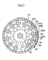
- the separating surface 34A is provided with plural substantially rectangular through-holes 34B arranged in parallel with each other. Corners of each through-hole 34B are rounded.
- a lifting member 36 serving as a second sheet receiving member is disposed inside the drum 34.
- the lifting member 36 is composed of base plates 37 having circular-arc-shape in a sectional view and fitting blocks 39 provided so as to respectively protrude from the base plates 37 in a radially outer direction and fit into the through-holes 34B.
- the height of the fitting blocks 39 is determined such that, when the fitting blocks 39 fit into the through-holes 34B, and in consequence there is no difference in level between fitting surfaces 39A of the fitting blocks 39 and the separating surface 34A and a cylindrical surface is thereby formed, external surfaces 37A of the base plates 37 abut against an internal circumferential wall 34C of the drum 34.
- a capability of adhering to the unvulcanized rubber sheet 12 may be imparted to the fitting surfaces 39A by using a material capable of adhering to the unvulcanized rubber sheet 12 (e.g., iron) to make the fitting blocks 39 themselves, or alternatively, by subjecting the fitting blocks 39 to surface treatment.
- a material capable of adhering to the unvulcanized rubber sheet 12 e.g., iron
- the base plates 37 are respectively supported by rods 38 of hydraulic jacks 40, which are respectively fixed to a drum shaft 42 of the drum 34 by fixtures (not shown).
- the rods 38 are lengthened or shortened, the lifting member 36 is expanded or contracted.
- the drum shaft 42 is rotatably supported by shaft supporting members 44. This structure enables the drum 34 to rotate in the direction of Arrow B.
- the unvulcanized rubber sheet 12 when the unvulcanized rubber sheet 12 is stuck, the unvulcanized rubber sheet 12 is supported by the separating surface 34A of the drum 34 and the fitting surfaces 39A of the lifting member 36 without a difference in level being created therebetween. In this state, the unvulcanized rubber sheet 12 is in close contact with the fitting surfaces 39A of the lifting member 36. Further, the plural fitting surfaces 39A, where the unvulcanized rubber sheet 12 and the lifting member 36 make contact with each other, enable the unvulcanized rubber sheet 12 to be held in a stable fashion.
- the separating surface 34A has no adhesive property, when the unvulcanized rubber sheet 12 is separated from the separating surface 34A, the unvulcanized rubber sheet 12 can be transferred and transported with a modicum of force.
- the third embodiment is basically identical to the second embodiment, the third embodiment differs from the second embodiment insofar that a separating surface 54A of a rubber member sticking device 50 is provided with plural substantially V-shaped through-holes 54B in a plan view, through-holes 54B being arranged in parallel with each other, as shown in Fig. 8.
- a lifting member 56 serving as a second sheet receiving member is disposed inside a drum 54.
- the lifting member 56 includes substantially V-shaped fitting blocks 59 in a plan view, fitting blocks 59 being capable of fitting into/retracting from the through-holes 54B. External surfaces of the fitting blocks 59 are formed as substantially V-shaped fitting surfaces 59A.
- the fitting surfaces 59A are respectively formed in a substantially V-shape and the fitting surfaces 59A make close contact with the unvulcanized rubber sheet 12 (not shown) at a certain angle to the widthwise direction of the unvulcanized rubber sheet 12, the unvulcanized rubber sheet 12 is easily separated from the fitting surfaces 59A.
- the fitting surfaces are pulled inside.
- the present invention is not limited to this method, and in sharp contrast the separating surface may be pushed outside.
- hydraulic jacks are used by way of example as a driving means.
- air or electricity may also be used as a driving source, and a driving means is not limited to hydraulic jacks.
- an unvulcanized rubber sheet is used by way of example as a viscous sheet.
- the present invention is not limited to an unvulcanized rubber sheet, and a plastic sheet, for example, may also be used.
- the rubber member sticking device according to the present invention is preferably used for holding and transferring a rubber sheet material, for example, in a case in which it is desired to prevent the rubber sheet material from becoming deformed and stretching during a separation operation, suppress loss of energy and eliminate traces of vacuum holes.
- An unvulcanized rubber sheet material for tires is preferably used as the rubber sheet material.
Landscapes
- Engineering & Computer Science (AREA)
- Mechanical Engineering (AREA)
- Tyre Moulding (AREA)
- Heating, Cooling, Or Curing Plastics Or The Like In General (AREA)
- Lining Or Joining Of Plastics Or The Like (AREA)
- Folding Of Thin Sheet-Like Materials, Special Discharging Devices, And Others (AREA)
Abstract
Description
Claims (7)
- A rubber member sticking device comprising:a first sheet receiving member including a separating surface capable of releasing from a sheet material;a second sheet receiving member including fitting surfaces capable of adhering to the sheet material; anda driving means driving the first sheet receiving member or the second sheet receiving member, such that, when the sheet material is stuck, the sheet material is supported by the separating surface and the fitting surfaces without a difference in level being created therebetween, and, when the sheet material is separated, the sheet material is supported only by the separating surface with a difference in level being created between the separating surface and the fitting surfaces.
- The rubber member sticking device according to claim 1, wherein a surface constituted of the separating surface and the fitting surfaces, for supporting the sheet material, is a flat surface.
- The rubber member sticking device according to claim 1, wherein a surface constituted of the separating surface and the fitting surfaces, for supporting the sheet material, is a cylindrical surface.
- The rubber member sticking device according to claim 3, wherein the sheet material is supported by a cylindrical body serving as a transfer drum for tires.
- The rubber member sticking device according to any of claims 1 to 4, wherein the separating surface of the first sheet receiving member is provided with a plurality of through-holes extending in a thickness direction of the first sheet receiving member, and the second sheet receiving member is provided so as to fit into/retract from the through-holes, so that the sheet material is supported by the fitting surfaces and the separating surface without a difference in level being created therebetween.
- The rubber member sticking device according to any of claims 1 to 5, wherein on a surface constituted of the separating surface and the fitting surfaces for supporting the sheet material, the fitting surfaces are respectively formed in a substantially V-shape in a plan view.
- The rubber member sticking device according to any of claims 1 to 4, wherein the second sheet receiving member is provided at both end portions of the first sheet receiving member such that, when the sheet material is stuck, both end portions of the sheet material make contact with the fitting surfaces.
Applications Claiming Priority (3)
| Application Number | Priority Date | Filing Date | Title |
|---|---|---|---|
| JP2002053961A JP2003252525A (en) | 2002-02-28 | 2002-02-28 | Device for placing viscous sheet material |
| JP2002053961 | 2002-02-28 | ||
| PCT/JP2003/002295 WO2003072475A1 (en) | 2002-02-28 | 2003-02-28 | Rubber member sticking device |
Publications (3)
| Publication Number | Publication Date |
|---|---|
| EP1489032A1 true EP1489032A1 (en) | 2004-12-22 |
| EP1489032A4 EP1489032A4 (en) | 2005-10-26 |
| EP1489032B1 EP1489032B1 (en) | 2006-07-19 |
Family
ID=27764378
Family Applications (1)
| Application Number | Title | Priority Date | Filing Date |
|---|---|---|---|
| EP03743059A Expired - Lifetime EP1489032B1 (en) | 2002-02-28 | 2003-02-28 | Rubber member sticking device |
Country Status (6)
| Country | Link |
|---|---|
| US (1) | US7578897B2 (en) |
| EP (1) | EP1489032B1 (en) |
| JP (1) | JP2003252525A (en) |
| DE (1) | DE60306909T2 (en) |
| ES (1) | ES2268386T3 (en) |
| WO (1) | WO2003072475A1 (en) |
Families Citing this family (2)
| Publication number | Priority date | Publication date | Assignee | Title |
|---|---|---|---|---|
| CN101310974B (en) | 2007-05-21 | 2010-08-25 | 北京京东方光电科技有限公司 | Film peeling device and method |
| JP5083975B2 (en) | 2008-04-07 | 2012-11-28 | 本田技研工業株式会社 | Fuel cell vehicle |
Family Cites Families (12)
| Publication number | Priority date | Publication date | Assignee | Title |
|---|---|---|---|---|
| JPS532474B2 (en) * | 1974-04-15 | 1978-01-28 | ||
| JPS5247957B2 (en) * | 1974-10-11 | 1977-12-06 | ||
| IT1099513B (en) * | 1978-10-25 | 1985-09-18 | Pirelli | PROCESS AND EQUIPMENT FOR THE MANUFACTURE OF RADIAL TIRES |
| JPH01157838A (en) * | 1987-08-20 | 1989-06-21 | Bridgestone Corp | Molded drum |
| EP0482830B1 (en) * | 1990-10-20 | 1995-12-13 | Sumitomo Rubber Industries Limited | Process for manufacturing green tyre and apparatus for the same |
| JP3193417B2 (en) * | 1991-10-07 | 2001-07-30 | 株式会社ブリヂストン | Drum for tire building |
| US5635016A (en) * | 1995-10-24 | 1997-06-03 | Wyko, Inc. | Transfer ring or drum apparatus with adjustable circumference |
| US5923408A (en) * | 1996-01-31 | 1999-07-13 | Canon Kabushiki Kaisha | Substrate holding system and exposure apparatus using the same |
| US6305677B1 (en) * | 1999-03-30 | 2001-10-23 | Lam Research Corporation | Perimeter wafer lifting |
| JP2001009928A (en) * | 1999-07-01 | 2001-01-16 | Mitsubishi Heavy Ind Ltd | Belt sticking device for large vehicle tires |
| JP2001301058A (en) * | 2000-04-26 | 2001-10-30 | Yokohama Rubber Co Ltd:The | Method and apparatus for attaching band-shaped material |
| JP3986728B2 (en) * | 2000-05-12 | 2007-10-03 | 横浜ゴム株式会社 | Transfer rubber drum |
-
2002
- 2002-02-28 JP JP2002053961A patent/JP2003252525A/en active Pending
-
2003
- 2003-02-28 WO PCT/JP2003/002295 patent/WO2003072475A1/en not_active Ceased
- 2003-02-28 DE DE60306909T patent/DE60306909T2/en not_active Expired - Fee Related
- 2003-02-28 ES ES03743059T patent/ES2268386T3/en not_active Expired - Lifetime
- 2003-02-28 US US10/505,866 patent/US7578897B2/en not_active Expired - Fee Related
- 2003-02-28 EP EP03743059A patent/EP1489032B1/en not_active Expired - Lifetime
Also Published As
| Publication number | Publication date |
|---|---|
| JP2003252525A (en) | 2003-09-10 |
| DE60306909D1 (en) | 2006-08-31 |
| EP1489032B1 (en) | 2006-07-19 |
| DE60306909T2 (en) | 2007-01-11 |
| WO2003072475A1 (en) | 2003-09-04 |
| ES2268386T3 (en) | 2007-03-16 |
| US20050158420A1 (en) | 2005-07-21 |
| EP1489032A4 (en) | 2005-10-26 |
| US7578897B2 (en) | 2009-08-25 |
Similar Documents
| Publication | Publication Date | Title |
|---|---|---|
| BR102013031409B1 (en) | APPLIANCE FOR SUPPORTING AND FIXING AN ANNULAR CORE SUBCONJUSTER AND TALON APEX | |
| KR100868977B1 (en) | Punching device for printed circuit board | |
| CN115179538B (en) | Rubber hose production equipment of washing machine | |
| JP2002331595A (en) | Unvulcanized rubber member for tire production and apparatus for producing unvulcanized rubber member for tire production | |
| EP1489032B1 (en) | Rubber member sticking device | |
| BR112017007499B1 (en) | Method and drum for manufacturing a tire, in particular a limited deflation tire | |
| WO2013179792A1 (en) | Device for mounting tread ring on base tire, and method for producing retread tire | |
| CN1404985A (en) | Auxiliary barrate with area-changeable negative-pressure surface | |
| JP2006240913A (en) | Press molding die and press molding method | |
| CN1642729A (en) | Expanded heat-insulating sheet, expanded heat-insulating container and their manufacturing method | |
| CN113997617A (en) | Air spring forming drum and air spring forming process method | |
| WO2019132914A1 (en) | End effector with pivoting arrangement for construction of spoke of non-pneumatic tire | |
| JPH03162912A (en) | Mold extracting device for cylindrical molding | |
| CN104661806B (en) | The withdrawing device of rigid core for building and the manufacture method of tire | |
| CN210758663U (en) | Mold core of corrugated pipe mold | |
| CN210403680U (en) | Transportation device for silicon wafer caching box and wafer separator | |
| CN111231349A (en) | A feeding device and a pore sleeve inlaying device comprising the feeding device | |
| CN207522918U (en) | A kind of pendulum material device for vulcanizer | |
| CN107379352A (en) | Vulcanization plant external mold, internal model, vulcanization plant and multistation vulcanization plant | |
| CN222273461U (en) | Refractory material apparatus for producing convenient to go up unloading | |
| KR100519622B1 (en) | Green tire loader | |
| CN210011208U (en) | Automatic material taking mechanism | |
| US11951732B2 (en) | Adhesive printing form attachment layer in tube shape, method for its manufacture, and method of printing using the same | |
| CN116118068B (en) | Vulcanizing equipment | |
| CN214472164U (en) | Vibration compaction forming machine |
Legal Events
| Date | Code | Title | Description |
|---|---|---|---|
| PUAI | Public reference made under article 153(3) epc to a published international application that has entered the european phase |
Free format text: ORIGINAL CODE: 0009012 |
|
| 17P | Request for examination filed |
Effective date: 20040831 |
|
| AK | Designated contracting states |
Kind code of ref document: A1 Designated state(s): AT BE BG CH CY CZ DE DK EE ES FI FR GB GR HU IE IT LI LU MC NL PT SE SI SK TR |
|
| RIN1 | Information on inventor provided before grant (corrected) |
Inventor name: SUZUKI, SHOJU |
|
| A4 | Supplementary search report drawn up and despatched |
Effective date: 20050909 |
|
| GRAP | Despatch of communication of intention to grant a patent |
Free format text: ORIGINAL CODE: EPIDOSNIGR1 |
|
| GRAS | Grant fee paid |
Free format text: ORIGINAL CODE: EPIDOSNIGR3 |
|
| GRAA | (expected) grant |
Free format text: ORIGINAL CODE: 0009210 |
|
| AK | Designated contracting states |
Kind code of ref document: B1 Designated state(s): DE ES FR GB IT |
|
| PG25 | Lapsed in a contracting state [announced via postgrant information from national office to epo] |
Ref country code: IT Free format text: LAPSE BECAUSE OF FAILURE TO SUBMIT A TRANSLATION OF THE DESCRIPTION OR TO PAY THE FEE WITHIN THE PRESCRIBED TIME-LIMIT;WARNING: LAPSES OF ITALIAN PATENTS WITH EFFECTIVE DATE BEFORE 2007 MAY HAVE OCCURRED AT ANY TIME BEFORE 2007. THE CORRECT EFFECTIVE DATE MAY BE DIFFERENT FROM THE ONE RECORDED. Effective date: 20060719 |
|
| REG | Reference to a national code |
Ref country code: GB Ref legal event code: FG4D |
|
| REF | Corresponds to: |
Ref document number: 60306909 Country of ref document: DE Date of ref document: 20060831 Kind code of ref document: P |
|
| ET | Fr: translation filed | ||
| PGFP | Annual fee paid to national office [announced via postgrant information from national office to epo] |
Ref country code: DE Payment date: 20070222 Year of fee payment: 5 |
|
| PGFP | Annual fee paid to national office [announced via postgrant information from national office to epo] |
Ref country code: GB Payment date: 20070228 Year of fee payment: 5 |
|
| REG | Reference to a national code |
Ref country code: ES Ref legal event code: FG2A Ref document number: 2268386 Country of ref document: ES Kind code of ref document: T3 |
|
| PGFP | Annual fee paid to national office [announced via postgrant information from national office to epo] |
Ref country code: ES Payment date: 20070327 Year of fee payment: 5 |
|
| PLBE | No opposition filed within time limit |
Free format text: ORIGINAL CODE: 0009261 |
|
| STAA | Information on the status of an ep patent application or granted ep patent |
Free format text: STATUS: NO OPPOSITION FILED WITHIN TIME LIMIT |
|
| 26N | No opposition filed |
Effective date: 20070420 |
|
| PGFP | Annual fee paid to national office [announced via postgrant information from national office to epo] |
Ref country code: IT Payment date: 20070618 Year of fee payment: 5 |
|
| PGFP | Annual fee paid to national office [announced via postgrant information from national office to epo] |
Ref country code: FR Payment date: 20070208 Year of fee payment: 5 |
|
| GBPC | Gb: european patent ceased through non-payment of renewal fee |
Effective date: 20080228 |
|
| REG | Reference to a national code |
Ref country code: FR Ref legal event code: ST Effective date: 20081031 |
|
| PG25 | Lapsed in a contracting state [announced via postgrant information from national office to epo] |
Ref country code: DE Free format text: LAPSE BECAUSE OF NON-PAYMENT OF DUE FEES Effective date: 20080902 |
|
| PG25 | Lapsed in a contracting state [announced via postgrant information from national office to epo] |
Ref country code: FR Free format text: LAPSE BECAUSE OF NON-PAYMENT OF DUE FEES Effective date: 20080229 |
|
| REG | Reference to a national code |
Ref country code: ES Ref legal event code: FD2A Effective date: 20080229 |
|
| PG25 | Lapsed in a contracting state [announced via postgrant information from national office to epo] |
Ref country code: GB Free format text: LAPSE BECAUSE OF NON-PAYMENT OF DUE FEES Effective date: 20080228 |
|
| PG25 | Lapsed in a contracting state [announced via postgrant information from national office to epo] |
Ref country code: ES Free format text: LAPSE BECAUSE OF NON-PAYMENT OF DUE FEES Effective date: 20080229 |
|
| PG25 | Lapsed in a contracting state [announced via postgrant information from national office to epo] |
Ref country code: IT Free format text: LAPSE BECAUSE OF NON-PAYMENT OF DUE FEES Effective date: 20080228 |