EP1489008A1 - Strapping machine with adjustable height work surface - Google Patents
Strapping machine with adjustable height work surface Download PDFInfo
- Publication number
- EP1489008A1 EP1489008A1 EP04011477A EP04011477A EP1489008A1 EP 1489008 A1 EP1489008 A1 EP 1489008A1 EP 04011477 A EP04011477 A EP 04011477A EP 04011477 A EP04011477 A EP 04011477A EP 1489008 A1 EP1489008 A1 EP 1489008A1
- Authority
- EP
- European Patent Office
- Prior art keywords
- work surface
- frame
- strap
- chute
- strapping
- Prior art date
- Legal status (The legal status is an assumption and is not a legal conclusion. Google has not performed a legal analysis and makes no representation as to the accuracy of the status listed.)
- Granted
Links
Images






Classifications
-
- B—PERFORMING OPERATIONS; TRANSPORTING
- B65—CONVEYING; PACKING; STORING; HANDLING THIN OR FILAMENTARY MATERIAL
- B65B—MACHINES, APPARATUS OR DEVICES FOR, OR METHODS OF, PACKAGING ARTICLES OR MATERIALS; UNPACKING
- B65B13/00—Bundling articles
- B65B13/02—Applying and securing binding material around articles or groups of articles, e.g. using strings, wires, strips, bands or tapes
- B65B13/04—Applying and securing binding material around articles or groups of articles, e.g. using strings, wires, strips, bands or tapes with means for guiding the binding material around the articles prior to severing from supply
- B65B13/06—Stationary ducts or channels
-
- B—PERFORMING OPERATIONS; TRANSPORTING
- B65—CONVEYING; PACKING; STORING; HANDLING THIN OR FILAMENTARY MATERIAL
- B65B—MACHINES, APPARATUS OR DEVICES FOR, OR METHODS OF, PACKAGING ARTICLES OR MATERIALS; UNPACKING
- B65B13/00—Bundling articles
- B65B13/18—Details of, or auxiliary devices used in, bundling machines or bundling tools
Definitions
- Known chute systems use a plurality of pins, generally located at about the comers of the chute, along with springs and torsion bars to locate and move the wall out of the strap path. While these known systems function well for their intended purposes, it is necessary to assure precise alignment of the pins, over the springs, and generally through openings in the walls or flanges that are formed as part of the walls. In addition, the torsion bars must all be configured so that the walls move in a predetermined sequence, a precise distance, to release the strap.
- a strapping machine of the type for feeding a strapping material around a load, positioning, tensioning and sealing the strapping material around the load is provided with a readily adjustable work surface or table height.
- Such a strapping machine includes a machine frame, a work surface for supporting a load, which surface is mounted to the frame.
- the machine includes a strap chute for carrying the strap around the load and for releasing the strap material from the strap chute, a feed assembly for conveying the strap around the strap chute and for retracting and tensioning the strap around the load and a weld head for sealing the strap to itself.
- a present machine includes openings in the work surface for accessing the adjusting rods (for rotation).
- One form of adjusting rod is a helically threaded rod that is engaged by an internally threaded nut
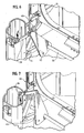
- FIG. 2 is an enlarged, partial view of the automatic chute opening system illustrated with the automatic opening contact arm resting on the (opening) work surface or conveyor section;
- FIG. 4 is a perspective view of the strapping machine chute opening system and chute track system showing the opening system moving toward the closed position;
- FIG. 8A is a cross-sectional view taken along line 8A-8A of FIG. 8;
- FIG. 16 is a cross-sectional view taken along line 16-16 of FIG. 15 in which the chute track is shown in the closed or operating position;
- FIG. 22 is a perspective view of the strapping machine illustrating the in-feed conveyor pivoted upwardly for removal;
- FIG. 27 is a side view similar to FIG. 26 illustrating the conveyor being positioned on the machine
- FIG. 30 is a side view illustrating the hinge assembly
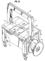
- the strapping machine 10 includes, generally, a frame 12, a strap chute 14, a feed assembly 16 and a weld head 18.
- a controller 20 provides automatic operation and control of the strapper 10.
- a table top or work surface 22 is disposed on the strapper 10 at the bottom of the chute 14.
- a dispenser 24 supplies strapping material to the feed assembly 16 and weld head 18.
- the feed assembly 16 is shown in part in FIG. 8 and the weld head 18 is shown in part in FIGS. 32-38.
- the present strapping machine 10 includes an automatic chute opening system 28 that is operably connected to the work surface 22.
- the chute opening system 28 opens the chute 14 upon upward pivoting of the work surface 22.
- FIGS. 10-12 there is shown a side view of the machine 10 with a portion of the work surface 22 in the closed position (FIG. 10) and as that portion of the surface 22 is pivoted upwardly (FIGS. 11-12).
- the chute opening assembly 28 includes a contact arm 30 that cooperates with the work surface 22 to rotate a torsion bar 32.
- the bar 32 is mounted to permit rotation within housing 35 (FIGS. 8-9A).
- the torsion bar 32 is rotated by a cam (not shown) to open the strap chute 14 through operation of the chute opening assembly 28.
- the arm 30 is biased to the open position by a spring 34 that urges the arm 30 rearwardly (toward the chute 14).
- the torsion bar 32 includes a linkage 44 that operably contacts the arm 30 by means of a pin (or screw) 45 that is mounted in the arm 30.
- the pin 45 engages and "pushes" the linkage 44 upwardly.
- a chute track system 46 opens the chute 14 by action of the pin 45 upwardly urging the linkage 44.
- FIGS. 6-7 illustrate the linkage 44 which includes a roller 48 (see FIGS. 14-15) that rides in an elongated slot 50 in the chute track system 46 for, as will be discussed below, moving the track system 46 between the open and closed positions.
Landscapes
- Engineering & Computer Science (AREA)
- Mechanical Engineering (AREA)
- Basic Packing Technique (AREA)
Abstract
Description
Claims (10)
- A strapping machine configured to feed a strapping material around a load, position, tension and seal the strapping material around the load, the strapping machine comprising:a machine frame;a work surface for supporting the load in the strapping machine, the work surface mounted to the frame;leg assemblies mounted to the frame for supporting the work surface above a floor;a strap chute for carrying the strap around the load and for releasing the strap material from the strap chute;a feed assembly configured to convey the strap around the strap chute and to retract and tension the strap around the load; anda weld head for sealing the strap to itself,the frame being mounted to the leg assemblies by first and second height adjustment assemblies, each configured to raise and lower a portion of the work surface relative to a fixed portion of the leg assemblies, each height adjustment assembly including a pair of adjusting rods lying along a respective side of the frame, at adjacent comers of the work surface, the adjusting rods operably connecting the work surface and the leg assemblies, each adjusting rod being secured to the leg assemblies by a support to restrain longitudinal movement and to provide rotational freedom relative to the leg assemblies and the frame, each adjusting rod being engaged with an engaging member longitudinally movable along the adjusting rod, the engaging member being mounted to the frame such that rotation of the adjusting rod raises or lowers the work surface relative to the leg assemblies.
- The strapping machine in accordance with claim 1 wherein the work surface has a generally rectangular shape and wherein the two height adjustment assemblies are each disposed at opposing sides of the work surface.
- The strapping machine in accordance with claim 2 wherein the adjusting rods of each pair of adjusting rods are operably connected to one another such that rotation of one of the pair of rods rotates the other of the pair of rods.
- The strapping machine in accordance with claim 3 wherein each adjusting rod includes a sprocket and wherein the sprockets are operably connected to one another by chain.
- The strapping machine in accordance with claim 1 wherein the adjusting rods are accessible for rotation though respective openings in the work surface.
- The strapping machine in accordance with claim 1 wherein the adjusting rods are formed having helical threads and wherein the engaging members are internally threaded bodies.
- The strapping machine in accordance with claim 6 wherein the internally threaded bodies are bronze nuts.
- The strapping machine in accordance with claim 1 including a height indicator, the height indicator including at least one scale on the frame associated with each height adjusting assembly and an indicator mounted on a respective leg assembly for cooperation with its associated scale.
- The strapping machine in accordance with claim 8 including a pair of height indicators, one associated with each of the first and second height adjustment assemblies, wherein each of the height indicators includes a scale on the frame and an indicator mounted on a respective leg assembly for cooperation with its associated scale.
- The strapping machine in accordance with claim 8 wherein the frame includes a slot formed therein for each of the height indicators and wherein the height indicators extend through their respective slots for cooperation with their associated scales.
Applications Claiming Priority (4)
| Application Number | Priority Date | Filing Date | Title |
|---|---|---|---|
| US47923103P | 2003-06-17 | 2003-06-17 | |
| US479231P | 2003-06-17 | ||
| US702145 | 2003-11-05 | ||
| US10/702,145 US6904841B2 (en) | 2003-06-17 | 2003-11-05 | Strapping machine with adjustable height work surface |
Publications (2)
| Publication Number | Publication Date |
|---|---|
| EP1489008A1 true EP1489008A1 (en) | 2004-12-22 |
| EP1489008B1 EP1489008B1 (en) | 2007-07-25 |
Family
ID=33424136
Family Applications (1)
| Application Number | Title | Priority Date | Filing Date |
|---|---|---|---|
| EP04011477A Expired - Lifetime EP1489008B1 (en) | 2003-06-17 | 2004-05-14 | Strapping machine with adjustable height work surface |
Country Status (6)
| Country | Link |
|---|---|
| US (1) | US6904841B2 (en) |
| EP (1) | EP1489008B1 (en) |
| AU (1) | AU2004202657B2 (en) |
| CA (1) | CA2467038C (en) |
| DE (1) | DE602004007723T2 (en) |
| ES (1) | ES2289394T3 (en) |
Cited By (2)
| Publication number | Priority date | Publication date | Assignee | Title |
|---|---|---|---|---|
| EP2208675A1 (en) * | 2009-01-15 | 2010-07-21 | SSB Strapping Systeme Bayreuth GmbH | Strapping machine |
| EP2208673A1 (en) * | 2009-01-15 | 2010-07-21 | SSB Strapping Systeme Bayreuth GmbH | Machine housing and strapping machine with same |
Families Citing this family (12)
| Publication number | Priority date | Publication date | Assignee | Title |
|---|---|---|---|---|
| US7490559B2 (en) * | 2003-11-25 | 2009-02-17 | Labor Aiding Systems, Inc. | Modular base for industrial tools |
| CN201077536Y (en) * | 2007-07-12 | 2008-06-25 | 杭州永创机械有限公司 | Packing frame device of binding machine |
| US11999516B2 (en) | 2008-04-23 | 2024-06-04 | Signode Industrial Group Llc | Strapping device |
| US10518914B2 (en) | 2008-04-23 | 2019-12-31 | Signode Industrial Group Llc | Strapping device |
| US8522678B2 (en) * | 2011-02-24 | 2013-09-03 | Tekpak Corporation | Strapping machine having a movable working assembly |
| DE102011075629B4 (en) | 2011-05-11 | 2016-09-15 | Smb Schwede Maschinenbau Gmbh | Method for controlling the tape drive device of a strapping machine and corresponding strapping machine |
| CN102530291B (en) * | 2011-12-22 | 2013-07-10 | 杭州永创智能设备股份有限公司 | Novel packing machine |
| CN107738773B (en) * | 2017-10-09 | 2023-04-14 | 石家庄市梓起机电设备科技有限公司 | Automatic steel pipe bundling equipment |
| CN112389706A (en) * | 2020-10-15 | 2021-02-23 | 苏州矽微电子科技有限公司 | Automatic bundling equipment |
| CN115489789A (en) * | 2022-08-16 | 2022-12-20 | 山东信发华信铝业有限公司 | Automatic aluminum rod bundling device |
| CN115258386B (en) * | 2022-09-29 | 2022-12-30 | 承德石油高等专科学校 | Transport case for wall map frame |
| CN120383039A (en) * | 2025-04-30 | 2025-07-29 | 温州兄弟机械有限公司 | Rail device for packer |
Citations (3)
| Publication number | Priority date | Publication date | Assignee | Title |
|---|---|---|---|---|
| DE3814029A1 (en) * | 1987-05-02 | 1988-11-17 | Hoesch Ag | Band-guide device of a tie-round apparatus |
| DE4340546A1 (en) * | 1992-12-15 | 1994-06-16 | Strapex Holding Ag | Portable modular binding machine - has binding guide frame comprising detachable elements fixed on knock-down framework for assembly on site |
| US5345749A (en) * | 1993-01-19 | 1994-09-13 | Greif Brothers Company | Bundler |
Family Cites Families (3)
| Publication number | Priority date | Publication date | Assignee | Title |
|---|---|---|---|---|
| US3627241A (en) * | 1970-06-02 | 1971-12-14 | Commerce Usa | Projected image viewer support |
| US3938766A (en) * | 1974-12-06 | 1976-02-17 | Garrett Tubular Products, Inc. | Adjustable typewriter platform mechanism |
| US6415712B1 (en) * | 1999-12-02 | 2002-07-09 | Enterprises International, Inc. | Track mechansim for guiding flexible straps around bundles of objects |
-
2003
- 2003-11-05 US US10/702,145 patent/US6904841B2/en not_active Expired - Lifetime
-
2004
- 2004-05-12 CA CA002467038A patent/CA2467038C/en not_active Expired - Fee Related
- 2004-05-14 DE DE602004007723T patent/DE602004007723T2/en not_active Expired - Lifetime
- 2004-05-14 ES ES04011477T patent/ES2289394T3/en not_active Expired - Lifetime
- 2004-05-14 EP EP04011477A patent/EP1489008B1/en not_active Expired - Lifetime
- 2004-06-17 AU AU2004202657A patent/AU2004202657B2/en not_active Ceased
Patent Citations (3)
| Publication number | Priority date | Publication date | Assignee | Title |
|---|---|---|---|---|
| DE3814029A1 (en) * | 1987-05-02 | 1988-11-17 | Hoesch Ag | Band-guide device of a tie-round apparatus |
| DE4340546A1 (en) * | 1992-12-15 | 1994-06-16 | Strapex Holding Ag | Portable modular binding machine - has binding guide frame comprising detachable elements fixed on knock-down framework for assembly on site |
| US5345749A (en) * | 1993-01-19 | 1994-09-13 | Greif Brothers Company | Bundler |
Cited By (2)
| Publication number | Priority date | Publication date | Assignee | Title |
|---|---|---|---|---|
| EP2208675A1 (en) * | 2009-01-15 | 2010-07-21 | SSB Strapping Systeme Bayreuth GmbH | Strapping machine |
| EP2208673A1 (en) * | 2009-01-15 | 2010-07-21 | SSB Strapping Systeme Bayreuth GmbH | Machine housing and strapping machine with same |
Also Published As
| Publication number | Publication date |
|---|---|
| DE602004007723T2 (en) | 2008-04-10 |
| AU2004202657B2 (en) | 2005-11-10 |
| CA2467038C (en) | 2007-10-09 |
| ES2289394T3 (en) | 2008-02-01 |
| EP1489008B1 (en) | 2007-07-25 |
| CA2467038A1 (en) | 2004-12-17 |
| US20050061164A1 (en) | 2005-03-24 |
| AU2004202657A1 (en) | 2005-01-13 |
| US6904841B2 (en) | 2005-06-14 |
| DE602004007723D1 (en) | 2007-09-06 |
Similar Documents
| Publication | Publication Date | Title |
|---|---|---|
| US6955119B2 (en) | Strapping machine with pivotal work surfaces having integral conveyors | |
| EP1489011B1 (en) | Strapping machine with automatic chute opening system | |
| EP1489008B1 (en) | Strapping machine with adjustable height work surface | |
| US6951170B2 (en) | Strapping machine with improved chute release system | |
| EP1961664B1 (en) | Improved strapping machine | |
| US6945164B2 (en) | Strapping machine with pivoting weld blade | |
| CA2475533C (en) | Improved side seal strapping machine |
Legal Events
| Date | Code | Title | Description |
|---|---|---|---|
| PUAI | Public reference made under article 153(3) epc to a published international application that has entered the european phase |
Free format text: ORIGINAL CODE: 0009012 |
|
| AK | Designated contracting states |
Kind code of ref document: A1 Designated state(s): AT BE BG CH CY CZ DE DK EE ES FI FR GB GR HU IE IT LI LU MC NL PL PT RO SE SI SK TR |
|
| AX | Request for extension of the european patent |
Extension state: AL HR LT LV MK |
|
| 17P | Request for examination filed |
Effective date: 20041221 |
|
| AKX | Designation fees paid |
Designated state(s): CH DE ES FR GB IT LI |
|
| GRAP | Despatch of communication of intention to grant a patent |
Free format text: ORIGINAL CODE: EPIDOSNIGR1 |
|
| GRAS | Grant fee paid |
Free format text: ORIGINAL CODE: EPIDOSNIGR3 |
|
| GRAA | (expected) grant |
Free format text: ORIGINAL CODE: 0009210 |
|
| AK | Designated contracting states |
Kind code of ref document: B1 Designated state(s): CH DE ES FR GB IT LI |
|
| REG | Reference to a national code |
Ref country code: GB Ref legal event code: FG4D |
|
| REG | Reference to a national code |
Ref country code: CH Ref legal event code: EP |
|
| REF | Corresponds to: |
Ref document number: 602004007723 Country of ref document: DE Date of ref document: 20070906 Kind code of ref document: P |
|
| REG | Reference to a national code |
Ref country code: ES Ref legal event code: FG2A Ref document number: 2289394 Country of ref document: ES Kind code of ref document: T3 |
|
| EN | Fr: translation not filed | ||
| PLBE | No opposition filed within time limit |
Free format text: ORIGINAL CODE: 0009261 |
|
| STAA | Information on the status of an ep patent application or granted ep patent |
Free format text: STATUS: NO OPPOSITION FILED WITHIN TIME LIMIT |
|
| 26N | No opposition filed |
Effective date: 20080428 |
|
| PG25 | Lapsed in a contracting state [announced via postgrant information from national office to epo] |
Ref country code: FR Free format text: LAPSE BECAUSE OF FAILURE TO SUBMIT A TRANSLATION OF THE DESCRIPTION OR TO PAY THE FEE WITHIN THE PRESCRIBED TIME-LIMIT Effective date: 20080321 |
|
| GBPC | Gb: european patent ceased through non-payment of renewal fee |
Effective date: 20080514 |
|
| PG25 | Lapsed in a contracting state [announced via postgrant information from national office to epo] |
Ref country code: GB Free format text: LAPSE BECAUSE OF NON-PAYMENT OF DUE FEES Effective date: 20080514 |
|
| REG | Reference to a national code |
Ref country code: DE Ref legal event code: R081 Ref document number: 602004007723 Country of ref document: DE Owner name: PREMARK PACKAGING LLC, GLENVIEW, US Free format text: FORMER OWNER: ILLINOIS TOOL WORKS INC., GLENVIEW, ILL., US Effective date: 20140729 Ref country code: DE Ref legal event code: R081 Ref document number: 602004007723 Country of ref document: DE Owner name: SIGNODE INTERNATIONAL IP HOLDINGS LLC, GLENVIE, US Free format text: FORMER OWNER: ILLINOIS TOOL WORKS INC., GLENVIEW, ILL., US Effective date: 20140729 |
|
| REG | Reference to a national code |
Ref country code: DE Ref legal event code: R081 Ref document number: 602004007723 Country of ref document: DE Owner name: SIGNODE INTERNATIONAL IP HOLDINGS LLC, GLENVIE, US Free format text: FORMER OWNER: PREMARK PACKAGING LLC, GLENVIEW, ILL., US Effective date: 20140912 |
|
| REG | Reference to a national code |
Ref country code: CH Ref legal event code: PUE Owner name: PREMARK PACKAGING LLC, US Free format text: FORMER OWNER: ILLINOIS TOOL WORKS INC., US Ref country code: CH Ref legal event code: PUE Owner name: SIGNODE INTERNATIONAL IP HOLDINGS LLC, US Free format text: FORMER OWNER: PREMARK PACKAGING LLC, US |
|
| REG | Reference to a national code |
Ref country code: ES Ref legal event code: PC2A Owner name: SIGNODE INTERNATIONAL IP HOLDINGS LLC Effective date: 20160510 |
|
| PGFP | Annual fee paid to national office [announced via postgrant information from national office to epo] |
Ref country code: ES Payment date: 20170601 Year of fee payment: 14 |
|
| REG | Reference to a national code |
Ref country code: ES Ref legal event code: FD2A Effective date: 20190913 |
|
| PG25 | Lapsed in a contracting state [announced via postgrant information from national office to epo] |
Ref country code: ES Free format text: LAPSE BECAUSE OF NON-PAYMENT OF DUE FEES Effective date: 20180515 |
|
| PGFP | Annual fee paid to national office [announced via postgrant information from national office to epo] |
Ref country code: CH Payment date: 20200603 Year of fee payment: 17 Ref country code: DE Payment date: 20200528 Year of fee payment: 17 |
|
| PGFP | Annual fee paid to national office [announced via postgrant information from national office to epo] |
Ref country code: IT Payment date: 20200522 Year of fee payment: 17 |
|
| REG | Reference to a national code |
Ref country code: DE Ref legal event code: R119 Ref document number: 602004007723 Country of ref document: DE |
|
| REG | Reference to a national code |
Ref country code: CH Ref legal event code: PL |
|
| PG25 | Lapsed in a contracting state [announced via postgrant information from national office to epo] |
Ref country code: LI Free format text: LAPSE BECAUSE OF NON-PAYMENT OF DUE FEES Effective date: 20210531 Ref country code: CH Free format text: LAPSE BECAUSE OF NON-PAYMENT OF DUE FEES Effective date: 20210531 |
|
| PG25 | Lapsed in a contracting state [announced via postgrant information from national office to epo] |
Ref country code: DE Free format text: LAPSE BECAUSE OF NON-PAYMENT OF DUE FEES Effective date: 20211201 |
|
| PG25 | Lapsed in a contracting state [announced via postgrant information from national office to epo] |
Ref country code: IT Free format text: LAPSE BECAUSE OF NON-PAYMENT OF DUE FEES Effective date: 20200514 |
|
| PG25 | Lapsed in a contracting state [announced via postgrant information from national office to epo] |
Ref country code: IT Free format text: LAPSE BECAUSE OF NON-PAYMENT OF DUE FEES Effective date: 20210514 |