EP1488949A2 - Drive control system and method for correcting axle torque - Google Patents
Drive control system and method for correcting axle torque Download PDFInfo
- Publication number
- EP1488949A2 EP1488949A2 EP04014404A EP04014404A EP1488949A2 EP 1488949 A2 EP1488949 A2 EP 1488949A2 EP 04014404 A EP04014404 A EP 04014404A EP 04014404 A EP04014404 A EP 04014404A EP 1488949 A2 EP1488949 A2 EP 1488949A2
- Authority
- EP
- European Patent Office
- Prior art keywords
- axle assembly
- torque
- vehicle
- power
- driving condition
- Prior art date
- Legal status (The legal status is an assumption and is not a legal conclusion. Google has not performed a legal analysis and makes no representation as to the accuracy of the status listed.)
- Withdrawn
Links
- 238000000034 method Methods 0.000 title claims description 48
- 230000000712 assembly Effects 0.000 claims abstract description 14
- 238000000429 assembly Methods 0.000 claims abstract description 14
- 230000005540 biological transmission Effects 0.000 claims description 28
- 230000001133 acceleration Effects 0.000 claims description 8
- 230000008859 change Effects 0.000 claims description 5
- 230000004044 response Effects 0.000 claims description 2
- 238000005096 rolling process Methods 0.000 description 26
- 230000008569 process Effects 0.000 description 24
- 238000012937 correction Methods 0.000 description 11
- 230000004048 modification Effects 0.000 description 9
- 238000012986 modification Methods 0.000 description 9
- 230000003247 decreasing effect Effects 0.000 description 4
- 230000001052 transient effect Effects 0.000 description 4
- 238000012546 transfer Methods 0.000 description 3
- 230000006399 behavior Effects 0.000 description 2
- 230000000630 rising effect Effects 0.000 description 2
- 230000002123 temporal effect Effects 0.000 description 2
- 230000008901 benefit Effects 0.000 description 1
- 238000007796 conventional method Methods 0.000 description 1
- 230000008878 coupling Effects 0.000 description 1
- 238000010168 coupling process Methods 0.000 description 1
- 238000005859 coupling reaction Methods 0.000 description 1
- 230000000694 effects Effects 0.000 description 1
- 239000000446 fuel Substances 0.000 description 1
- 230000006870 function Effects 0.000 description 1
- 230000007246 mechanism Effects 0.000 description 1
- 238000012545 processing Methods 0.000 description 1
- 230000009467 reduction Effects 0.000 description 1
- 239000004065 semiconductor Substances 0.000 description 1
- 230000035939 shock Effects 0.000 description 1
Images


Classifications
-
- B—PERFORMING OPERATIONS; TRANSPORTING
- B60—VEHICLES IN GENERAL
- B60W—CONJOINT CONTROL OF VEHICLE SUB-UNITS OF DIFFERENT TYPE OR DIFFERENT FUNCTION; CONTROL SYSTEMS SPECIALLY ADAPTED FOR HYBRID VEHICLES; ROAD VEHICLE DRIVE CONTROL SYSTEMS FOR PURPOSES NOT RELATED TO THE CONTROL OF A PARTICULAR SUB-UNIT
- B60W10/00—Conjoint control of vehicle sub-units of different type or different function
- B60W10/04—Conjoint control of vehicle sub-units of different type or different function including control of propulsion units
- B60W10/06—Conjoint control of vehicle sub-units of different type or different function including control of propulsion units including control of combustion engines
-
- B—PERFORMING OPERATIONS; TRANSPORTING
- B60—VEHICLES IN GENERAL
- B60K—ARRANGEMENT OR MOUNTING OF PROPULSION UNITS OR OF TRANSMISSIONS IN VEHICLES; ARRANGEMENT OR MOUNTING OF PLURAL DIVERSE PRIME-MOVERS IN VEHICLES; AUXILIARY DRIVES FOR VEHICLES; INSTRUMENTATION OR DASHBOARDS FOR VEHICLES; ARRANGEMENTS IN CONNECTION WITH COOLING, AIR INTAKE, GAS EXHAUST OR FUEL SUPPLY OF PROPULSION UNITS IN VEHICLES
- B60K28/00—Safety devices for propulsion-unit control, specially adapted for, or arranged in, vehicles, e.g. preventing fuel supply or ignition in the event of potentially dangerous conditions
- B60K28/10—Safety devices for propulsion-unit control, specially adapted for, or arranged in, vehicles, e.g. preventing fuel supply or ignition in the event of potentially dangerous conditions responsive to conditions relating to the vehicle
- B60K28/16—Safety devices for propulsion-unit control, specially adapted for, or arranged in, vehicles, e.g. preventing fuel supply or ignition in the event of potentially dangerous conditions responsive to conditions relating to the vehicle responsive to, or preventing, spinning or skidding of wheels
- B60K28/165—Safety devices for propulsion-unit control, specially adapted for, or arranged in, vehicles, e.g. preventing fuel supply or ignition in the event of potentially dangerous conditions responsive to conditions relating to the vehicle responsive to, or preventing, spinning or skidding of wheels acting on elements of the vehicle drive train other than the propulsion unit and brakes, e.g. transmission, clutch, differential
-
- B—PERFORMING OPERATIONS; TRANSPORTING
- B60—VEHICLES IN GENERAL
- B60W—CONJOINT CONTROL OF VEHICLE SUB-UNITS OF DIFFERENT TYPE OR DIFFERENT FUNCTION; CONTROL SYSTEMS SPECIALLY ADAPTED FOR HYBRID VEHICLES; ROAD VEHICLE DRIVE CONTROL SYSTEMS FOR PURPOSES NOT RELATED TO THE CONTROL OF A PARTICULAR SUB-UNIT
- B60W10/00—Conjoint control of vehicle sub-units of different type or different function
- B60W10/10—Conjoint control of vehicle sub-units of different type or different function including control of change-speed gearings
- B60W10/11—Stepped gearings
-
- B—PERFORMING OPERATIONS; TRANSPORTING
- B60—VEHICLES IN GENERAL
- B60W—CONJOINT CONTROL OF VEHICLE SUB-UNITS OF DIFFERENT TYPE OR DIFFERENT FUNCTION; CONTROL SYSTEMS SPECIALLY ADAPTED FOR HYBRID VEHICLES; ROAD VEHICLE DRIVE CONTROL SYSTEMS FOR PURPOSES NOT RELATED TO THE CONTROL OF A PARTICULAR SUB-UNIT
- B60W10/00—Conjoint control of vehicle sub-units of different type or different function
- B60W10/18—Conjoint control of vehicle sub-units of different type or different function including control of braking systems
- B60W10/184—Conjoint control of vehicle sub-units of different type or different function including control of braking systems with wheel brakes
-
- B—PERFORMING OPERATIONS; TRANSPORTING
- B60—VEHICLES IN GENERAL
- B60W—CONJOINT CONTROL OF VEHICLE SUB-UNITS OF DIFFERENT TYPE OR DIFFERENT FUNCTION; CONTROL SYSTEMS SPECIALLY ADAPTED FOR HYBRID VEHICLES; ROAD VEHICLE DRIVE CONTROL SYSTEMS FOR PURPOSES NOT RELATED TO THE CONTROL OF A PARTICULAR SUB-UNIT
- B60W30/00—Purposes of road vehicle drive control systems not related to the control of a particular sub-unit, e.g. of systems using conjoint control of vehicle sub-units
- B60W30/02—Control of vehicle driving stability
- B60W30/045—Improving turning performance
-
- B—PERFORMING OPERATIONS; TRANSPORTING
- B60—VEHICLES IN GENERAL
- B60W—CONJOINT CONTROL OF VEHICLE SUB-UNITS OF DIFFERENT TYPE OR DIFFERENT FUNCTION; CONTROL SYSTEMS SPECIALLY ADAPTED FOR HYBRID VEHICLES; ROAD VEHICLE DRIVE CONTROL SYSTEMS FOR PURPOSES NOT RELATED TO THE CONTROL OF A PARTICULAR SUB-UNIT
- B60W2520/00—Input parameters relating to overall vehicle dynamics
- B60W2520/26—Wheel slip
- B60W2520/263—Slip values between front and rear axle
-
- B—PERFORMING OPERATIONS; TRANSPORTING
- B60—VEHICLES IN GENERAL
- B60W—CONJOINT CONTROL OF VEHICLE SUB-UNITS OF DIFFERENT TYPE OR DIFFERENT FUNCTION; CONTROL SYSTEMS SPECIALLY ADAPTED FOR HYBRID VEHICLES; ROAD VEHICLE DRIVE CONTROL SYSTEMS FOR PURPOSES NOT RELATED TO THE CONTROL OF A PARTICULAR SUB-UNIT
- B60W2520/00—Input parameters relating to overall vehicle dynamics
- B60W2520/28—Wheel speed
-
- B—PERFORMING OPERATIONS; TRANSPORTING
- B60—VEHICLES IN GENERAL
- B60W—CONJOINT CONTROL OF VEHICLE SUB-UNITS OF DIFFERENT TYPE OR DIFFERENT FUNCTION; CONTROL SYSTEMS SPECIALLY ADAPTED FOR HYBRID VEHICLES; ROAD VEHICLE DRIVE CONTROL SYSTEMS FOR PURPOSES NOT RELATED TO THE CONTROL OF A PARTICULAR SUB-UNIT
- B60W2540/00—Input parameters relating to occupants
- B60W2540/18—Steering angle
-
- B—PERFORMING OPERATIONS; TRANSPORTING
- B60—VEHICLES IN GENERAL
- B60W—CONJOINT CONTROL OF VEHICLE SUB-UNITS OF DIFFERENT TYPE OR DIFFERENT FUNCTION; CONTROL SYSTEMS SPECIALLY ADAPTED FOR HYBRID VEHICLES; ROAD VEHICLE DRIVE CONTROL SYSTEMS FOR PURPOSES NOT RELATED TO THE CONTROL OF A PARTICULAR SUB-UNIT
- B60W2710/00—Output or target parameters relating to a particular sub-units
- B60W2710/06—Combustion engines, Gas turbines
- B60W2710/0666—Engine torque
-
- B—PERFORMING OPERATIONS; TRANSPORTING
- B60—VEHICLES IN GENERAL
- B60W—CONJOINT CONTROL OF VEHICLE SUB-UNITS OF DIFFERENT TYPE OR DIFFERENT FUNCTION; CONTROL SYSTEMS SPECIALLY ADAPTED FOR HYBRID VEHICLES; ROAD VEHICLE DRIVE CONTROL SYSTEMS FOR PURPOSES NOT RELATED TO THE CONTROL OF A PARTICULAR SUB-UNIT
- B60W2710/00—Output or target parameters relating to a particular sub-units
- B60W2710/10—Change speed gearings
- B60W2710/105—Output torque
Definitions
- the present invention relates to a driving condition control method and system installed in a vehicle, which are capable of controlling the driving conditions of the vehicle.
- the technique disclosed in the former publication estimates the rising slope of a road surface according to accelerating resistance torque.
- the technique corrects the gear ratios of the automatic transmission (AT) of a vehicle, thereby keeping torque during the running of the vehicle on the rising slope of the road surface.
- the technique also obtains sequential data representing fluctuations of the target torque, and obtains the fluctuations of the target torque.
- the technique adds the obtained fluctuations of the target torque to the previous transient target torque to obtain a present transient target torque.
- the technique performs a transient control of the target torque while the steady target torque fluctuates.
- another technique disclosed in Japanese Unexamined Patent Publication No. 2000-297664 prevents, when the operating state of an accelerator pedal of a vehicle by the driver is kept constant, a shock from occurring in the vehicle according to sudden change of the driving resistance of the vehicle.
- the technique estimates a driving resistance according to the vehicle speed and the vehicle acceleration to determine the target torque based on the estimated driving resistance.
- the present invention is made on the background for providing a driving condition control method and system that are capable of correcting a loss of a torque to improve the torque efficiency of a vehicle.
- a driving condition control system installed in a vehicle.
- the vehicle has a source of power for generating power, a first rotatable axle assembly to which a front wheel is attached, and a second rotatable axle assembly to which a rear wheel is attached.
- the power is transferred to the second rotatable axle assembly so that the second rotatable axle assembly is rotated to generate torque.
- the driving condition control system comprises a sensing unit configured to sense a first physical quantity indicative of a rotation of the first rotatable axle assembly and a second physical quantity indicative of a rotation of the second rotatable axle assembly.
- the driving condition control system also comprises a correcting unit configured to correct the torque according to the sensed first and second physical quantities of the rotations of the first and second rotational axle assemblies.
- a program product having a computer-readable medium of an electronic control unit.
- the computer-readable medium stores therein a program.
- the electronic control unit is installed in a vehicle.
- the vehicle has a source of power for generating power, a first rotatable axle assembly to which a front wheel is attached, and a second rotatable axle assembly to which a rear wheel is attached.
- the power is transferred to the second rotatable axle assembly so that the second rotatable axle assembly is rotated to generate torque.
- the vehicle also has a sensing unit that senses a first physical quantity indicative of a rotation of the first rotatable axle assembly and a second physical quantity indicative of a rotation of the second rotatable axle assembly.
- the program causes an electronic control unit to receive the first physical quantity indicative of the rotation of the first rotatable axle assembly and the second physical quantity indicative of the rotation of the second rotatable axle assembly from the sensing unit.
- the program causes an electronic control unit to correct the torque according to the sensed first and second physical quantities of the rotations of the first and second rotational axle assemblies.
- Fig. 1 is a schematic structural view of a driving condition control system according to a first embodiment of the present invention.
- the driving condition control system CS is installed in a vehicle, such as four-wheel automobile, V that is a type of front-engine-rear-drive vehicles.
- the vehicle V is provided with an engine 5, a drive shaft 20, and an automatic transmission (AT) 7 having a gear box and mechanically connected between the engine 5 and one end of the drive shaft 20.
- the AT 7 changes the gear ratios of the gear box independently of the driver to convert the engine's power output to torque based on the gear ratios, thereby transferring the torque to the drive shaft 20.
- the vehicle V is also provided with a front axle assembly (rolling axle assembly) 11a and a rear axle assembly (drive axle assembly) 11b.
- the front axle assembly 11a has a supporting member, a right-front axle 11a1, and a left-front axle 11a2 that are individually rotatably supported therewith.
- Front left and right wheels FL and FR are fixed to the right-front axle 11a1 and the left-front axle 11a2, respectively.
- the differential 21 is mechanically coupled to the other end of the drive shaft 20.
- the left-rear axle 11 b2 is supported at its one end with the differential 21 to be rotatable around its axial direction orthogonal to the axial direction of the drive shaft 20.
- the right-rear axle 11 is supported at its one end with the differential 21 to be rotatable around its axial direction orthogonal to the drive shaft's axial direction.
- the differential 21 converts the rotation of the drive shaft DF to each rotation of each of the right and left rear wheels (right and left rear axles 11b1 and 11b2), and allows the right and left rear wheels RR and Rl to revolve at different speeds during turns.
- the vehicle V has a steering wheel 12 that the driver can operate and a steering mechanism 25 mechanically connected to the steering wheel 12 and the front right and left wheels FR and FF.
- the driver's steering operation of the steering wheel 12 allows the front right and left wheels FR and FL to steer, thereby turning (steering) the vehicle V.
- the driving condition control system CS is equipped with a plurality of sensors 1a-1d, 2, and 3, a manager ECU (Electronic Control Unit) 4, an engine ECU 6, a transmission ECU 8, the brake ECU 9, and braking force generating units 10a-10d.
- a manager ECU Electronic Control Unit 4
- an engine ECU 6 a transmission ECU 8
- the brake ECU 9 a braking force generating units 10a-10d.
- the sensors include wheel speed sensors 1a-1d, an engine revolution sensor 2, and an intake air mass sensor 3.
- the wheel speed sensors 1a, 1b, 1c, and 1d are disposed close to the wheels FR, FL, RR, and RL, respectively.
- the wheel speed sensors 1a-1d are electrically connected to, for example, each of the ECUs 4, 6, 8, and 9.
- Each of the wheel speed signals can be used for calculating the wheel speed of each of the wheels FR-RL, the speed Vso of the vehicle body, the slip ratio indicative of how much slipping is occurring between the wheels FR-RL and the road surface, and the like.
- each of the wheel speed signals can be used for calculating rotational state of each of the front and rear axle assemblies 11a and 11b to which the wheels are attached. That is, the wheel speed signals allow physical quantity indicative of the rotation of each of the front and rear axle assemblies 11a and 11b.
- the rotational speeds Vd and Vr of the driving axle assembly (rear axle assembly) 11b and the front axle assembly 11a are used.
- the revolutions of the rear axle assembly 11b and the front axle assembly 11a may be used.
- the engine revolution sensor 2 is electrically connected to the engine ECU 6 and operative to output an engine revolution signal indicative of the revolution of the engine 5 that is served as power source for generating power (torque), thereby outputting the engine revolution signal to the engine ECU 6.
- the intake air mass sensor 3 senses intake air mass of the engine 5 to output the sensed intake air mass as intake air mass signal to the engine ECU 6.
- the driving condition control system CS includes the engine revolution sensor 2 and the intake air mass sensor 3, but they can be omitted from the structure of the system CS.
- the engine revolution and the intake air mass can be estimated according to an engine control signal outputted from the engine ECU 6.
- the manager ECU 4 receives the engine control signal outputted from the engine ECU 6 and a transmission control signal outputted from the transmission ECU 8.
- the manager ECU 4 also receives a brake control signal outputted from the brake ECU 9 and the wheel speed signals outputted from the wheel speed sensors 1a-1d.
- the manager ECU 4 performs various operations including any one of an engine control operation, a brake control operation, and a transmission control operation, for controlling the driving conditions of the vehicle V according to the received signals.
- the manager ECU 4 outputs at least one control signal based on the operation result. At least one of the engine ECU 6, the brake ECU 9, and the transmission ECU 8 receives the at least one control signal to perform at least one of the control operations corresponding to the at least one control signal.
- the engine ECU 6, which corresponds to, for example, a power control unit, is operative to control the power of the engine 5 according to the position of an accelerator pedal 30 that is operated by the drier and sensed by an accelerator pedal sensor 31.
- the accelerator pedal 30 determines to control the flow of fuel into the engine 5.
- the engine ECU 6 determines the engine control signal including a command that makes the engine 5 output predetermined engine power (torque Td) according to the position of the accelerator pedal 30, and the engine ECU 6 outputs the engine control signal to the engine 5.
- the engine ECU 6 adjusts the predetermined power according to the received engine revolution signal, the received intake air mass signal, the control signal outputted from the manager ECU 4.
- the engine ECU 6 normally determines the engine power that corresponds to the position of the accelerator pedal 30 to generate the engine control signal indicative of the determined engine power.
- the engine ECU 6 calculates power control parameters, such as the torque of the engine and the engine revolution, that are required to reduce the amount of engine power.
- the engine ECU 6 outputs the engine control signal indicative of the calculated power control parameters to the engine 5.
- the torque of the engine 5 and the engine revolution are adjusted according to the engine control signal, thereby reducing the amount of engine power.
- the transmission ECU 8 is operative to change the gear ratios of the AT 7 according to the position of a shift lever (not shown). That is, the transmission ECU 8 determines the transmission control signal indicative the predetermined gear ratios that correspond to the position of the shift lever, thereby outputting the transmission control signal to the AT 7.
- the transmission control signal allows the AT 7 to change its current gear ratios to the predetermined gear ratios that correspond to the position of the shift lever.
- the transmission ECU 8 adjusts the predetermined gear ratios according to the received wheel speed signals outputted from the sensors 1a-1d, the control signal indicative of the torque calculated by the engine ECU 6, and so on.
- the transmission ECU 8 outputs the transmission control signal that allows the AT 7 to adjust the gear ratios to correspond to the engine torque and the wheel speeds. In the AT 7, the gear ratios are adjusted according to the transmission control signal.
- each of the brake force generating units 10a-10d is electrically connected to each of the brakes and the brake ECU (electronic control unit) 9 described hereinafter.
- Each of the brake force generating units 10a-10d is provided with, for example, a wheel cylinder (W/C) that is mechanically connected to each of the brake shoes.
- W/C wheel cylinder
- Each of the wheel cylinders is operative to convert hydraulic pressure to mechanical force as the brake force, thereby applying it on each of the brake shoes.
- each brake shoe causes each brake shoe to press against the inside of each of the brake drums, thereby stopping the rotation of each wheel by friction between each of the brake drums and each of the brake shoes.
- the brake ECU 9 which corresponds to, for example, a brake control unit, is operative to control the brakes according to the position of a brake pedal 32 operated by the drier and sensed by a brake pedal sensor 33.
- the brake ECU 9 determines the brake control signal that allows each of the brake force generating units 10a-10d to generate predetermined brake force according to the position of the brake pedal 32, and the brake ECU 9 outputs the brake control signal to each of the brake force generating units 10a-10d.
- the brake ECU 9 adjusts the predetermined brake force according to the received wheel speed signals outputted from the sensors 1a-1d and the control signal outputted from the manager ECU 4.
- the brake ECU 9 calculates the wheel speeds Vw and the vehicle body speed Vso of the vehicle body according to the wheel speed signals so as to calculate the slip ratio based on the calculated wheel speeds Vw and the vehicle body speed Vso. Subsequently, the brake ECU 9 detects a locking tendency in the wheels FR-RL according to the calculated slip ratio, thereby outputting to each of the brake force generating units 10a-10d the brake control signal for ABS (Anti Lock Braking System) control.
- ABS Anti Lock Braking System
- the brake control signal can prevent an event representing a rapid reduction in speed where one or more wheels begin to lock-up from occurring.
- Each of the brake force generating units 10a-10d adjusts the generated brake force according to the brake control signal.
- the engine power generated by the engine 5 is transferred through the automatic transmission 7 and the rear axle assembly 11b to the rear wheels (driving wheels) RR and RL so that the rear wheels RR and RL are rotated to generate torque.
- the generated torque is transferred to the front wheels (rolling wheels) FR and FL to rotate them. If the torque on the rear wheels RR and RL is transferred to the rolling wheels FR and FL without losing at least a little of the torque, the driving wheels RR and RL and the rolling wheels FR and FL would be equally rotated.
- the driving condition control system CS obtains the relationship between the rotational conditions of each driving wheel and each rolling wheel to correct the loss of the torque according to the obtained relationship, thereby improving the transmission efficiency between each driving wheel and each rolling wheel.
- the rotational speed of the front axle assembly that is the rolling axle assembly 11a, to which the front wheels FR and FL are attached
- rolling axle speed Vr the rotational speed of the rear axle assembly
- drive axle speed Vd the rotational speed of the rear axle assembly
- Vr/Vd The ratio of the rolling axle speed Vr and the drive axle speed Vd, which is referred to as "Vr/Vd", represents the degree of the loss of the torque.
- the driving condition control system CS uses the ratio "Vr/Vd" as a correction coefficient to correct the torque according to the correction coefficient "Vr/Vd".
- the driving condition control system CS performs the following processes on the basis of the above concept.
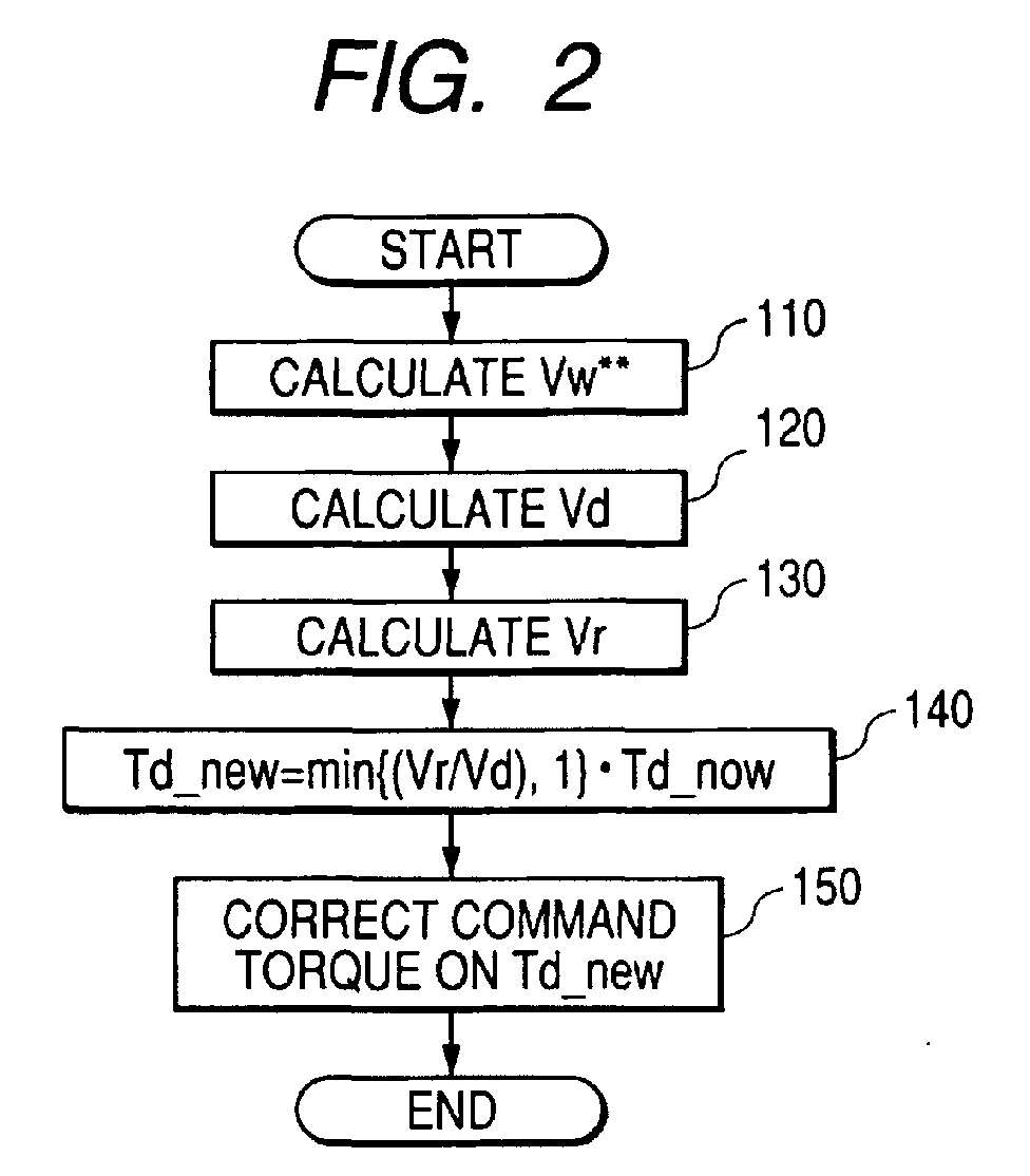
- Fig. 2 shows a flowchart of processes that the manager ECU 4 executes, explaining the processes of the driving condition control system CS in detail based on the flowchart.
- the manager ECU 4 performs these processes based on a program P previously installed in a computer-readable medium, such as ROM (Read Only Memory), RAM (Random Access Memory), a semiconductor memory and so on, which is installed in the manager ECU 4.
- ROM Read Only Memory
- RAM Random Access Memory
- manager ECU 4 periodically performs the following processes.
- step 110 the manager ECU 4 calculates the wheel speed Vw** of each of the wheels FR, FL, RR, and RL according to the wheel speed signals outputted from the wheel speed sensors 1a-1d.
- This reference character "Vw**" collectively represents each of the wheel speeds of each of the wheels FR, FL, RR, and RL.
- an identifier of the front wheel FR such as "FR”
- this process obtains each of the wheel speeds VwFR, VwFL, VwRR, and VwRL of each of the wheels FR, FL, RR, and RL.
- step 120 the manager ECU 4 calculates, as the drive axle speed Vd representing physical quantity of the rotation of the drive axle assembly (rear axle assembly) 11b, an average value of the wheel speeds VwRR and VwRL of the rear wheels RR and RL.
- step 130 the manager ECU 4 calculates, as the rolling axle speed Vr representing physical quantity of the rotation of the rolling axle assembly (front axle assembly) 11a, an average value of the wheel speeds VwFR and VwFL of the front wheels FR and FL.
- step 140 the manager ECU 4 performs the torque Td of the engine 5.
- the manager ECU 4 multiplies the previous value Td_now of the torque Td by the less of the of the previous value "Vr/Vd” and 1, thereby obtaining the new value "Td_new”. Then, the torque Td of the engine 5 generated by the engine 5 according to the engine control signal is outputted from the engine ECU 6.
- step 150 the manager ECU 4 calculates the command torque according to the calculated new value "Td_new" and output to the engine ECU 6 the control signal requesting the engine ECU 6 to output the engine control signal including the command torque.
- the engine ECU 6 adjusts the engine torque to meet the command torque independently of the position of the accelerator pedal 30, thereby controlling the torque transferred to the drive axle assembly 11 b (the drive wheels RR and RL).
- the driving condition control system CS corrects the loss of the torque due to the unstable driving condition.
- the "unstable driving condition” represents vehicle's driving conditions that are different from the driver's intended driving conditions. For example, when turning at a corner, the behaviors of the vehicle V shift from a driver's intended behavior, as shown in Fig. 3.
- Fig. 3 shows a condition that, when turning at the corner, the front portion of the vehicle V turns or likely turns towards inside more than the steady turning condition corresponding to the driver's intended (inputted) steering by the steering wheel 12.
- the approximately circular broken line around a predetermined turning center represents the turning track based of the steady turning condition.
- This driving condition shown in Fig. 3 is referred to as "unstable condition of inside turning", such as oversteer.
- the unstable condition of the inside turning is caused by instability of energy transfer with respect to the front and rear wheels FR, FL, RR, and RL.
- the unstable condition of the inside turning during, for example, acceleration occurs because excess acceleration energy to drive the rear wheels RR and RL is given to the drive axle, as compared with the steady turning condition.
- the manager ECU 4 determines that the correction coefficient "Vr/Vd" is more than 1 at arbitrary time t1, in other words, the rolling axle speed Vr is faster than the drive axle speed Vd, the manager ECU 4 outputs, as the new value Td_new of the torque Td, the previous value Td_new as it is.
- the manager ECU 4 when determining that the rolling axle speed Vr is later than the drive axle speed Vd, controls to decrease the command torque Td of the engine 5 corresponding to the driver's intention (operating amount of the accelerator pedal 30). Specifically, the manager ECU 4 multiplies the command torque Td by the correction coefficient "Tr/Td" that is less than 1 to decrease the command torque Td of the engine 5.
- the loss of the torque is corrected according to the rotational speeds of the rolling axle assembly 11a and the drive axle assembly 11b, which represent the rotational conditions thereof.
- the manager ECU 4 carries out the decreasing of the engine power (engine torque) to overcome the unstable conditions of the vehicle V.
- the manager ECU 4 of the driving condition control system adjusts the torque based on another processes.
- the manager ECU 4 carries out the adjustment of the torque based on the braking forces.
- Processes executed by the manager ECU 4 according to the second embodiment are partially different from those executed by the manager ECU 4 according to the first embodiment so that these partially different processes of the management ECU 4 according to the second embodiment will be explained hereinafter.
- the remaining processes and the structure of the driving condition control system according to the second embodiment are substantially identical with those of the driving condition control system according to the first embodiment, so that explanations thereabout are omitted.
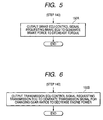
- the manager ECU 4 makes the brake ECU 9 perform the brake force generation process through each of the brake force generating units 10a-10d without adjusting the command torque included in the engine control signal.
- the management ECU 4 for decreasing the torque, outputs to the brake ECU 9 the control signal requesting the brake ECU 9 to generate the brake force (step 150A).
- the brake ECU 9 produces the brake control signal in response to the reception of the control signal outputted form the manager ECU 4, thereby outputting the brake control signal to each of the brake force generating units 10a-10d.
- Each of the brake force generating units 10a-10d applies the brake force (mechanical force) on each of the brake shoes, thereby braking each of the wheels FR, FL, RR, and RL.
- the brake forces applied on the front and rear wheels FR, FL, RR, and RL may be approximately constant, or may be differently distributed between the front wheels FR, FL and the rear wheels RR, RL.
- the brake forces applied on the front and rear wheels FR, FL, RR, and RL may also be differently distributed between the inside wheels and the outside wheels during turning.
- This structure allows the torque transferred to the drive axle assembly 11b to decrease, making it possible to correct the loss of the torque, thereby obtaining the same effects as the first embodiment.
- the adjustment of the torque is performed according to the ratio of the rotational conditions of the drive axle assembly and the rolling axle assembly.
- the adjustment of the torque may be performed according to the difference between the rotational conditions of the drive axle assembly and the rolling axle assembly.
- the difference between the rotational conditions of the drive axle assembly and the rolling axle assembly corresponds to the loss of the torque.
- This correspondence makes it possible to adjust the torque by subtracting a correction amount of torque based on the difference between the rotational conditions of the drive axle assembly and the rolling axle assembly from the command torque.
- the adjustment of the torque is performed by adjusting the engine power or the brake force.
- the management ECU 4 for decreasing the torque, may output to the transmission ECU 8 the control signal requesting the transmission ECU 8 to generate the transmission signal for changing the gear ratios to decrease the engine power corresponding to the driver's intention (Fig. 6; step 150B).
- This control of the gear ratios allows the torque transferred to the drive axle assembly 11b to be adjusted.
- the driving condition control system can correct the loss of the torque at any time during the running of the vehicle V.
- step 110 when determining the driver's operation of the steering wheel 12 (Fig. 7 step 108), the manager ECU 4 shifts to step 110 (step 109) to perform these processes in steps 110-150 according to the flowcharts shown in Figs. 2, 5-7. That is, in this modification, it is possible to perform the torque loss correcting processes only when the vehicle V is turning.
- these steps (processes) shown in Figs. 2, 5-7 are performed by the manager ECU 4, but they may be performed by at least two of the ECUs in combination, or other one of the ECUs.
- These steps (processes) shown in Figs. 2, 5-7 in combination or alone correspond to processing units of the present invention.
- the driving condition control system according to the present invention may provide a plurality of hard-wired logic circuits that perform these processes in place of the manager ECU 4.
- each of the driving condition control systems according to the first and second embodiments and modifications thereof may be installed in another vehicle, such as two-wheel automobile.
Landscapes
- Engineering & Computer Science (AREA)
- Chemical & Material Sciences (AREA)
- Combustion & Propulsion (AREA)
- Transportation (AREA)
- Mechanical Engineering (AREA)
- Automation & Control Theory (AREA)
- Arrangement And Driving Of Transmission Devices (AREA)
- Control Of Vehicle Engines Or Engines For Specific Uses (AREA)
- Arrangement And Mounting Of Devices That Control Transmission Of Motive Force (AREA)
- Control Of Driving Devices And Active Controlling Of Vehicle (AREA)
- Regulating Braking Force (AREA)
Abstract
Description
Claims (17)
- A driving condition control system installed in a vehicle, wherein said vehicle has a source of power for generating power, a first rotatable axle assembly to which a front wheel is attached, and a second rotatable axle assembly to which a rear wheel is attached, said power being transferred to the second rotatable axle assembly so that the second rotatable axle assembly is rotated to generate torque, said driving condition control system comprising:a sensing unit configured to sense a first physical quantity indicative of a rotation of the first rotatable axle assembly and a second physical quantity indicative of a rotation of the second rotatable axle assembly; anda correcting unit configured to correct the torque according to the sensed first and second physical quantities of the rotations of the first and second rotational axle assemblies.
- A driving condition control system according to claim 1, wherein said correcting unit is configured to correct the torque according to a difference between the first and second physical quantities of the rotations of the first and second rotational axle assemblies.
- A driving condition control system according to claim 1, wherein said correcting unit is configured to correct the torque according to a ratio between the first and second physical quantities of the rotations of the first and second rotational axle assemblies.
- A driving condition control system according to claim 1, wherein said sensing unit is configured to sense a first rotational speed of the first rotational axle assembly and a second rotational speed of the second rotational axle assembly as the first and second physical quantities.
- A driving condition control system according to claim 1, wherein said correcting unit is configured to correct the power generated by the source of power to correct the torque.
- A driving condition control system according to claim 1, wherein said vehicle has an acceleration pedal, said source of power is an engine for generating the power according to a command value inputted by a driver's operation of the acceleration pedal, and
said correcting unit is configured to correct the command value to correct the torque. - A driving condition control system according to claim 1, further comprising:wherein said correcting unit is configured to cause the brake force control unit to control the plurality of brake force generating units to generate the brake forces, said braking forces correcting the torque.a plurality of brake force generating units mechanically connected to the front and rear wheels of the vehicle and configured to generate brake forces to apply the brake forces to the front and rear wheels, respectively; anda brake force control unit operatively connected to the plurality of brake force generating units and configured to control the generated brake forces,
- A driving condition control system according to claim 1, wherein said vehicle is equipped with an automatic transmission that has a gear box and mechanically connected between the source of power and the second rotatable axle assembly, said automatic transmission changing gear ratios of the gear box to convert the power generated by the source to torque based on the gear ratios, thereby transferring the torque to the second axle assembly,
wherein said correcting unit is electrically connected to the automatic transmission and configured to control the automatic transmission to change the gear ratios, thereby adjusting the torque. - A driving condition control system according to claim 1, further comprising a turning determining unit configured to determine whether the vehicle is turning,
wherein said sensing unit starts to sense the first physical quantity of the rotation of the first rotatable axle assembly and the second physical quantity indicative of the rotation of the second rotatable axle assembly in response to the determination of the turning determining unit1 in that the vehicle is turning. - A program product having a computer-readable medium storing therein a program readable by an electronic control unit, said electronic control unit being installed in a vehicle, wherein said vehicle has a source of power for generating power, a first rotatable axle assembly to which a front wheel is attached, a second rotatable axle assembly to which a rear wheel is attached, said power being transferred to the second rotatable axle assembly so that the second rotatable axle assembly is rotated to generate torque, and a sensing unit that senses a first physical quantity indicative of a rotation of the first rotatable axle assembly and a second physical quantity indicative of a rotation of the second rotatable axle assembly, said program causing an electronic control unit to:receive the first physical quantity indicative of the rotation of the first rotatable axle assembly and the second physical quantity indicative of the rotation of the second rotatable axle assembly from the sensing unit; andcorrect the torque according to the sensed first and second physical quantities of the rotations of the first and second rotational axle assemblies.
- A method of controlling a driving condition of a vehicle, wherein said vehicle has a source of power for generating power, a first rotatable axle assembly to which a front wheel is attached, and a second rotatable axle assembly to which a rear wheel is attached, said power being transferred to the second rotatable axle assembly so that the second rotatable axle assembly is rotated to generate torque, said method comprising:sensing a first physical quantity indicative of a rotation of the first rotatable axle assembly and a second physical quantity indicative of a rotation of the second rotatable axle assembly; andcorrecting the torque according to the sensed first and second physical quantities of the rotations of the first and second rotational axle assemblies.
- A method of controlling a driving condition of a vehicle according to claim 11, wherein said correcting step corrects the torque according to a difference between the first and second physical quantities of the rotations of the first and second rotational axle assemblies.
- A method of controlling a driving condition of a vehicle according to claim 11, wherein said correcting step corrects the torque according to a ratio between the first and second physical quantities of the rotations of the first and second rotational axle assemblies.
- A method of controlling a driving condition of a vehicle according to claim 11, wherein said sensing step senses a first rotational speed of the first rotational axle assembly and a second rotational speed of the second rotational axle assembly as the first and second physical quantities.
- A method of controlling a driving condition of a vehicle according to claim 11, wherein said correcting step corrects the power generated by the source of power to correct the torque.
- A method of controlling a driving condition of a vehicle according to claim 11, wherein said vehicle has an acceleration pedal, said source of power is an engine for generating the power according to a command value inputted by a driver's operation of the acceleration pedal, and
said correcting step corrects the command value to correct the torque. - A method of controlling a driving condition of a vehicle according to claim 11, further comprising:wherein said correcting step generates the plurality of brake forces acting on the front and rear wheels, respectively, thereby correcting the torque.generating brake forces to apply the brake forces to the front and rear wheels, respectively; andcontrolling the generated brake forces,
Applications Claiming Priority (2)
| Application Number | Priority Date | Filing Date | Title |
|---|---|---|---|
| JP2003173853 | 2003-06-18 | ||
| JP2003173853A JP2005008019A (en) | 2003-06-18 | 2003-06-18 | Vehicle running state control system and vehicle running state control method |
Publications (2)
| Publication Number | Publication Date |
|---|---|
| EP1488949A2 true EP1488949A2 (en) | 2004-12-22 |
| EP1488949A3 EP1488949A3 (en) | 2009-12-23 |
Family
ID=33410957
Family Applications (1)
| Application Number | Title | Priority Date | Filing Date |
|---|---|---|---|
| EP04014404A Withdrawn EP1488949A3 (en) | 2003-06-18 | 2004-06-18 | Drive control system and method for correcting axle torque |
Country Status (3)
| Country | Link |
|---|---|
| US (1) | US7241249B2 (en) |
| EP (1) | EP1488949A3 (en) |
| JP (1) | JP2005008019A (en) |
Families Citing this family (2)
| Publication number | Priority date | Publication date | Assignee | Title |
|---|---|---|---|---|
| DE102005057805B4 (en) * | 2005-12-03 | 2017-05-18 | Bayerische Motoren Werke Aktiengesellschaft | Device for controlling an automatic transmission with an electronic control unit |
| US12545229B2 (en) * | 2019-01-10 | 2026-02-10 | Carlson Paving Products, Inc. | Steering control system |
Citations (4)
| Publication number | Priority date | Publication date | Assignee | Title |
|---|---|---|---|---|
| JPH09242862A (en) | 1996-03-07 | 1997-09-16 | Hitachi Ltd | Road gradient estimating device and automatic transmission control device |
| JPH10329585A (en) | 1997-06-02 | 1998-12-15 | Nissan Motor Co Ltd | Vehicle driving force control device |
| JP2000297664A (en) | 1999-04-12 | 2000-10-24 | Nissan Motor Co Ltd | Vehicle driving force control device |
| JP2003173853A (en) | 2001-12-06 | 2003-06-20 | Sharp Corp | Socket for semiconductor integrated circuit |
Family Cites Families (14)
| Publication number | Priority date | Publication date | Assignee | Title |
|---|---|---|---|---|
| JPH0637166B2 (en) * | 1985-12-10 | 1994-05-18 | 株式会社曙ブレ−キ中央技術研究所 | Driving force control device for self-propelled vehicle |
| DE3901257A1 (en) * | 1988-01-28 | 1989-08-03 | Volkswagen Ag | WARNING DEVICE |
| US4926333A (en) * | 1988-04-20 | 1990-05-15 | Mitsubishi Jidosha Kogyo Kabushiki Kaisha | Traction control apparatus |
| US5172319A (en) * | 1989-11-13 | 1992-12-15 | Honda Giken Kogyo Kabushiki Kaisha | Drive wheel slip control system for vehicle |
| US5025882A (en) * | 1990-01-19 | 1991-06-25 | General Motors Corporation | Vehicle traction control system |
| JPH03249350A (en) * | 1990-02-27 | 1991-11-07 | Mitsubishi Motors Corp | Power controller for vehicle |
| US5315519A (en) * | 1991-10-03 | 1994-05-24 | General Motors Corporation | Method of sensing excessive slip in a wheel slip control system |
| JP3393654B2 (en) * | 1991-12-25 | 2003-04-07 | マツダ株式会社 | Vehicle slip control device |
| JPH07186926A (en) * | 1993-12-28 | 1995-07-25 | Mazda Motor Corp | Vehicle traction control device |
| JP3564863B2 (en) * | 1996-02-16 | 2004-09-15 | 日産自動車株式会社 | Vehicle driving force control device |
| DE19913825A1 (en) * | 1999-03-26 | 2000-09-28 | Bosch Gmbh Robert | Regulating system for vehicle has drive slip regulator that influences drive unit power or torque implemented in drive unit controller, second controller for wheel brake braking force(s) |
| JP2004090886A (en) * | 2002-09-04 | 2004-03-25 | Advics:Kk | Vehicle traction control device |
| JP3870911B2 (en) * | 2003-02-10 | 2007-01-24 | 日産自動車株式会社 | Lane departure prevention device |
| JP4148038B2 (en) * | 2003-06-18 | 2008-09-10 | 株式会社デンソー | Vehicle running state control system and vehicle running state control method |
-
2003
- 2003-06-18 JP JP2003173853A patent/JP2005008019A/en active Pending
-
2004
- 2004-06-17 US US10/869,506 patent/US7241249B2/en not_active Expired - Fee Related
- 2004-06-18 EP EP04014404A patent/EP1488949A3/en not_active Withdrawn
Patent Citations (4)
| Publication number | Priority date | Publication date | Assignee | Title |
|---|---|---|---|---|
| JPH09242862A (en) | 1996-03-07 | 1997-09-16 | Hitachi Ltd | Road gradient estimating device and automatic transmission control device |
| JPH10329585A (en) | 1997-06-02 | 1998-12-15 | Nissan Motor Co Ltd | Vehicle driving force control device |
| JP2000297664A (en) | 1999-04-12 | 2000-10-24 | Nissan Motor Co Ltd | Vehicle driving force control device |
| JP2003173853A (en) | 2001-12-06 | 2003-06-20 | Sharp Corp | Socket for semiconductor integrated circuit |
Also Published As
| Publication number | Publication date |
|---|---|
| US7241249B2 (en) | 2007-07-10 |
| US20040259681A1 (en) | 2004-12-23 |
| EP1488949A3 (en) | 2009-12-23 |
| JP2005008019A (en) | 2005-01-13 |
Similar Documents
| Publication | Publication Date | Title |
|---|---|---|
| JP3937524B2 (en) | Vehicle braking / driving force control device | |
| US5850616A (en) | Traction control system for four wheel drive vehicle and the method thereof | |
| US6076033A (en) | Process for controlling yaw moment in vehicle | |
| US10392008B2 (en) | Control device for four-wheel drive vehicle | |
| US7125086B2 (en) | Vehicle dynamics control system | |
| US6634451B2 (en) | Power distribution control system for a vehicle | |
| US5497333A (en) | Control system for integrally controlling operations of electronic torque split system and traction control system for automotive vehicle | |
| JPH08207607A (en) | Traction controller for four-wheel drive vehicle | |
| JPH10295004A (en) | Drive control device for electric vehicles | |
| JP3607985B2 (en) | Vehicle body speed estimation device and control device | |
| US20180281760A1 (en) | Control device for four-wheel drive vehicle | |
| JP2001287561A (en) | Driving force control device for four-wheel drive vehicle | |
| JP4193706B2 (en) | Road surface friction coefficient detector | |
| EP1400390A2 (en) | Power distribution control apparatus for four wheel drive vehicle | |
| US7169083B2 (en) | Driving condition control method and system | |
| US11285809B2 (en) | Travel control apparatus for four-wheel drive vehicle | |
| US10889290B2 (en) | Control apparatus for four-wheel-drive vehicle | |
| CN108025709B (en) | Motor vehicle traction control system and method | |
| JP3827837B2 (en) | Vehicle motion control device | |
| JP4114065B2 (en) | Four-wheel drive vehicle behavior control device | |
| US7241249B2 (en) | Driving condition control method and system | |
| JP3781101B2 (en) | Braking force control device for vehicle | |
| JP2006282146A (en) | Vehicle attitude control device | |
| JP4055225B2 (en) | Vehicle braking / driving force control device | |
| JP2009234301A (en) | Vehicle body speed estimation device for four-wheel drive vehicle |
Legal Events
| Date | Code | Title | Description |
|---|---|---|---|
| PUAI | Public reference made under article 153(3) epc to a published international application that has entered the european phase |
Free format text: ORIGINAL CODE: 0009012 |
|
| AK | Designated contracting states |
Kind code of ref document: A2 Designated state(s): AT BE BG CH CY CZ DE DK EE ES FI FR GB GR HU IE IT LI LU MC NL PL PT RO SE SI SK TR |
|
| AX | Request for extension of the european patent |
Extension state: AL HR LT LV MK |
|
| PUAL | Search report despatched |
Free format text: ORIGINAL CODE: 0009013 |
|
| AK | Designated contracting states |
Kind code of ref document: A3 Designated state(s): AT BE BG CH CY CZ DE DK EE ES FI FR GB GR HU IE IT LI LU MC NL PL PT RO SE SI SK TR |
|
| AX | Request for extension of the european patent |
Extension state: AL HR LT LV MK |
|
| 17P | Request for examination filed |
Effective date: 20100616 |
|
| AKX | Designation fees paid |
Designated state(s): DE FR GB |
|
| 17Q | First examination report despatched |
Effective date: 20110222 |
|
| STAA | Information on the status of an ep patent application or granted ep patent |
Free format text: STATUS: THE APPLICATION IS DEEMED TO BE WITHDRAWN |
|
| 18D | Application deemed to be withdrawn |
Effective date: 20140103 |