EP1488939A1 - Pneumatic tire - Google Patents
Pneumatic tire Download PDFInfo
- Publication number
- EP1488939A1 EP1488939A1 EP03712870A EP03712870A EP1488939A1 EP 1488939 A1 EP1488939 A1 EP 1488939A1 EP 03712870 A EP03712870 A EP 03712870A EP 03712870 A EP03712870 A EP 03712870A EP 1488939 A1 EP1488939 A1 EP 1488939A1
- Authority
- EP
- European Patent Office
- Prior art keywords
- bead
- bead core
- folded
- tire
- ply
- Prior art date
- Legal status (The legal status is an assumption and is not a legal conclusion. Google has not performed a legal analysis and makes no representation as to the accuracy of the status listed.)
- Granted
Links
- 239000011324 bead Substances 0.000 claims abstract description 113
- 229920001971 elastomer Polymers 0.000 claims abstract description 27
- 230000003014 reinforcing effect Effects 0.000 claims description 31
- 230000002787 reinforcement Effects 0.000 abstract 3
- 230000001965 increasing effect Effects 0.000 description 10
- 239000000835 fiber Substances 0.000 description 5
- 239000004677 Nylon Substances 0.000 description 3
- 229910000831 Steel Inorganic materials 0.000 description 3
- 239000004760 aramid Substances 0.000 description 3
- 229920003235 aromatic polyamide Polymers 0.000 description 3
- 230000002542 deteriorative effect Effects 0.000 description 3
- 229920001778 nylon Polymers 0.000 description 3
- 239000010959 steel Substances 0.000 description 3
- 229920000297 Rayon Polymers 0.000 description 2
- 239000010426 asphalt Substances 0.000 description 2
- 230000000052 comparative effect Effects 0.000 description 2
- 230000000694 effects Effects 0.000 description 2
- 238000011156 evaluation Methods 0.000 description 2
- 239000002964 rayon Substances 0.000 description 2
- 230000001953 sensory effect Effects 0.000 description 2
- 230000006866 deterioration Effects 0.000 description 1
- 238000006073 displacement reaction Methods 0.000 description 1
- 230000002708 enhancing effect Effects 0.000 description 1
- 239000000446 fuel Substances 0.000 description 1
- 238000000034 method Methods 0.000 description 1
- 238000012986 modification Methods 0.000 description 1
- 230000004048 modification Effects 0.000 description 1
- 229920000728 polyester Polymers 0.000 description 1
- 229920006149 polyester-amide block copolymer Polymers 0.000 description 1
- 238000010998 test method Methods 0.000 description 1
Images

Classifications
-
- B—PERFORMING OPERATIONS; TRANSPORTING
- B60—VEHICLES IN GENERAL
- B60C—VEHICLE TYRES; TYRE INFLATION; TYRE CHANGING; CONNECTING VALVES TO INFLATABLE ELASTIC BODIES IN GENERAL; DEVICES OR ARRANGEMENTS RELATED TO TYRES
- B60C15/00—Tyre beads, e.g. ply turn-up or overlap
- B60C15/06—Flipper strips, fillers, or chafing strips and reinforcing layers for the construction of the bead
-
- Y—GENERAL TAGGING OF NEW TECHNOLOGICAL DEVELOPMENTS; GENERAL TAGGING OF CROSS-SECTIONAL TECHNOLOGIES SPANNING OVER SEVERAL SECTIONS OF THE IPC; TECHNICAL SUBJECTS COVERED BY FORMER USPC CROSS-REFERENCE ART COLLECTIONS [XRACs] AND DIGESTS
- Y10—TECHNICAL SUBJECTS COVERED BY FORMER USPC
- Y10T—TECHNICAL SUBJECTS COVERED BY FORMER US CLASSIFICATION
- Y10T152/00—Resilient tires and wheels
- Y10T152/10—Tires, resilient
- Y10T152/10495—Pneumatic tire or inner tube
- Y10T152/10819—Characterized by the structure of the bead portion of the tire
-
- Y—GENERAL TAGGING OF NEW TECHNOLOGICAL DEVELOPMENTS; GENERAL TAGGING OF CROSS-SECTIONAL TECHNOLOGIES SPANNING OVER SEVERAL SECTIONS OF THE IPC; TECHNICAL SUBJECTS COVERED BY FORMER USPC CROSS-REFERENCE ART COLLECTIONS [XRACs] AND DIGESTS
- Y10—TECHNICAL SUBJECTS COVERED BY FORMER USPC
- Y10T—TECHNICAL SUBJECTS COVERED BY FORMER US CLASSIFICATION
- Y10T152/00—Resilient tires and wheels
- Y10T152/10—Tires, resilient
- Y10T152/10495—Pneumatic tire or inner tube
- Y10T152/10819—Characterized by the structure of the bead portion of the tire
- Y10T152/10837—Bead characterized by the radial extent of apex, flipper or chafer into tire sidewall
Definitions
- the present invention relates to a pneumatic tire which enhances steering stability by providing a bead reinforcing layer having a reinforcing cord between a bead core and a carcass ply.
- a reinforcing layer using steel cord or organic fiber cord is conventionally provided over a wide range from a bead portion to a sidewall portion to enhance the flexural rigidity of the sidewall.
- the tire vertical rigidity is increased and thus, the riding comfort is deteriorated. Further, stress is prone to be concentrated on an outer end of the reinforcing layer.
- the reinforcing layer is used for a high performance tire in which a tire aspect ratio is reduced to 55% or lower and a ground-contact width and a ground-contact area are increased, a flexible region of the sidewall portion becomes narrow and stress is concentrated more. Thus, there is a tendency that the endurance is deteriorated.
- the present inventor focused attention on a fact that not only the tire lateral rigidity but also twisting rigidity of the bead portion largely affected the steering stability, and researched.
- the inventor found that the tire vertical rigidity could be maintained at low level and the steering stability could be enhanced without deteriorating the riding comfort if a reinforcing layer in which reinforcing cords were arranged at a predetermined angle and which had a folded-back portion was formed around the bead core without projecting the reinforcing layer from a bead apex rubber, and the bead core and the bead apex rubber were formed integral with each other, and the twisting rigidity of the bead portion was enhanced.
- the steering stability can be enhanced also by increasing the width of the bead core to increase the twisting rigidity and to enhance the fitting performance between the bead core and a rim.
- the steel amount of the bead core and a rubber amount of the bead apex rubber are increased, there is a problem that the tire weight is increased and the fuel performance is deteriorated.
- a predetermined reinforcing layer is provided around a bead core, it is an object of the present invention to provide a pneumatic tire capable of enhancing the steering stability without deteriorating the riding comfort and without excessively increasing the tire weight.
- the present invention provides a pneumatic tire, comprising a carcass including a carcass ply having a ply body portion which extends from a tread portion to a bead core of a bead portion through a sidewall portion and which is continuously provided with a ply folded-up portion folded up around the bead core from its inner side to its outer side in the tire axial direction, and a bead apex rubber passing between the ply body portion and the ply folded-up portion and extending radially outward of the tire from a radially outer surface of the bead core, wherein the bead portion is provided with a bead reinforcing layer which is arranged from an inner portion of the bead core located inward in the tire axial direction through a bottom portion passing radially inward and which is connected to an outer portion of the bead core outward in the tire axial direction and which is arranged at an angle of 20 to 60° with respect to a tire circumferential
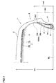
- a width H1 of the folded-back portion of the bead reinforcing layer in the radial direction is 5 to 40 mm. It is preferable that a radial height H2 of the outer portion of the bead reinforcing layer from a bead base line is 1.5 to 4.5 times a radial height H3 of the bead apex rubber, and is smaller than a radial height H4 of the bead apex rubber. It is preferable that a radial height H5 of the ply folded-up portion of the carcass ply is greater than the height H4 of the bead apex rubber.
- bead base line means a line in the tire axial direction passing through a bead diameter position defined in a standard on which tires are based.
- the pneumatic tire of the invention is a high performance passenger automobile tire having a tire aspect ratio of 55% or lower.
- the pneumatic tire 1 includes a carcass 6 extending from a tread portion 2 to a bead core 5 of a bead portion 4 through a sidewall portion 3, and a belt layer 7 disposed on the inner side of the tread portion 2 and on the outer side of the carcass 6.
- the bead portion 4 is provided with a bead apex rubber 8 extendingfrom a radially outer surface of the tire of the bead core 5 to radially outward of the tire.
- the belt layer 7 comprises two or more, in this example, two belt plies 7A and 7B in which high elastic belt cords are arranged in a tire circumferential direction at an angle of 10 to 35° for example. Inclination directions of the belt plies 7A and 7B are changed such that the belt cords intersect with each other between the plies. With this configuration, the belt rigidity is enhanced, and substantially the entire width of the tread portion 2 is strongly reinforced with a hoop effect.
- a steel cord or an organic fiber cord having high modulus such as aromatic polyamide fiber is preferably used as the belt cord.
- a band layer 9 is disposed on an outer side of the belt layer 7.
- the band layer 9 includes a band cord which is helically wound in the tire circumferential direction at an angle of 5° or less for example.
- the band layer 9 extends such as to wrap at least an outer end of the belt layer 7 in the tire axial direction.
- the carcass 6 comprises one or more, in this example, one carcass ply 6A in which a carcass cord is arranged at an angle of 75 to 90° with respect to the tire circumferential direction.
- the carcass ply 6A is integrally provided with a ply body portion 6a extending between the bead cores 5 and 5, and with a ply folded-up portion 6b which is folded up around the bead core 5 from the inner side to the outer side in the tire axial direction on both ends of the ply body portion 6a.
- An organic fiber cord such as nylon, rayon, polyester, and aromatic polyamide can preferably be used as the carcass cord.
- the bead apex rubber 8 passes between the ply body portion 6a and the ply folded-up portion 6b of the carcass 6, and has a triangular cross section which is tapered radially outward of the tire.
- a radial height H4 of the bead apex rubber 8 from the bead base line BL is set in a range of 0.25 to 0.5 times a height HT of a tire cross section.
- a radial height H5 of the ply folded-up portion 6b from the bead base line BL is set greater than the height H4, thereby forming an extending portion 6b1 extending beyond the bead apex rubber 8.
- the extending portion 6b1 and the ply body portion 6a are adjacent to each other.
- the bead portion 4 is provided with a bead reinforcing layer 10.
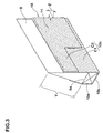
- the bead reinforcing layer 10 comprises one cord ply in which reinforcing cords 11 are arranged at an angle ⁇ (20 to 60°) with respect to the tire circumferential direction.
- Organic fiber cord such as nylon, polyester, rayon, and aromatic polyamide can be used as the reinforcing cord 11.
- Nylon cord is especially preferable because the thickness of the cord can be increased by folding the same.
- the bead reinforcing layer 10 comprises an inner portion 10a located on the inner side of the bead core 5 in the tire axial direction, a bottom portion 10b passing radially inward of the bead core 5, and an outer portion 10c located on the outer side of the bead core 5 in the tire axial direction. These portions 10a, 10b and 10c are continuously connected to one another to form the U-shape.
- the inner portion 10a passes between the bead core 5 and the ply body portion 6, and the outer portion 10c passes between the bead core 5 and the ply folded-up portion 6b.
- the bead reinforcing layer 10 brings the bead core 5 and the bead apex rubber 8 into tight contact with each other to wrap them in the U-shape and integrally couples the bead core 5 and the bead apex rubber 8 to each other strongly.
- the outer portion 10c includes a main portion C1 which is connected to the bottom portion 10b and extends to the region Y which is adjacent to the bead apex rubber 8, and a folded-back portion C2 which is folded back at a radial outer end Ce of the main portion C1 and superposed on the main portion C1 and extends radially inward.
- the folded-back portion C2 is terminated radially inward of the radially outer surface 5s of the bead core 5.
- a cord angle ⁇ of the bead reinforcing layer 10 is in a range of 20 to 60°.
- the reinforcing cords 11 intersect with each other at an angle of 2 ⁇ to form a strong intersecting structure between the main portion C1 and the folded-back portion C2.
- a width H1 of the folded-back portion C2 in the radial direction is in a range of 5 to 40 mm. If the width H1 is less than 5 mm, the twisting rigidity is insufficient, and if the width H1 exceeds 40 mm, the riding comfort is deteriorated.
- the radial height H2 of the outer portion 10c is 1.5 to 4.5 times the radial height H3 of the bead core 5. If the height H2 is less than 1.5 times, the twisting rigidity is insufficient, and if the height H2 exceeds 4.5 times, the riding comfort is deteriorated.
- the outer portion 10c of the bead reinforcing layer 10 is lower than the bead apex rubber 8, the stress concentration on the outer end Ce can be reduced. Since the ply folded-up portion 6b covers the outer end Ce, bead damage such as cord loose can be suppressed.
- the bead reinforcing layer 10 is formed with the folded-back portion C2, the bead core 5 is displaced axially inward by a distance corresponding to the thickness of the folded-back portion C2. As a result, the fitting performance with respect to the rim is enhanced, and this configuration also enhances the steering stability.
- Tires of 215/45ZR17 size were prototyped based on the specifications shown in Table 1.
- the steering stability, riding comfort and weight of the prototyped tire were measured and compared with each other. Specifications not shown in Table 1 are substantially the same.
- the test method is as follows:
- the tires were mounted on all rims (17 ⁇ 7JJ) of a passenger vehicle (Japanese FR vehicle, displacement of 2500cc) under internal pressure of 200 kPa, and the vehicle was run on a dry asphalt road at a speed of 120 km/H.
- the straight running stability and lane change stability at that time were evaluated by a driver's sensory evaluation on a scale of 10 while a comparative example was defined as 5. A greater value indicates more excellent result.
- the weight of one tire was measured.
- the pneumatic tire of the invention is provided with a bead reinforcing layer having a predetermined structure around the bead core. Therefore, it is possible to enhance the steering stability without deteriorating the riding comfort and without excessively increasing the tire weight.
Landscapes
- Engineering & Computer Science (AREA)
- Mechanical Engineering (AREA)
- Tires In General (AREA)
Abstract
Description
the bead portion is provided with a bead reinforcing layer which is arranged from an inner portion of the bead core located inward in the tire axial direction through a bottom portion passing radially inward and which is connected to an outer portion of the bead core outward in the tire axial direction and which is arranged at an angle of 20 to 60° with respect to a tire circumferential direction,
the outer portion includes a main portion which extends radially outward of the tire beyond the radially outer surface of the bead core to a region adjacent to the bead apex rubber, and a folded-back portion which is folded back at a radially outer end and terminated radially inward of the radially outer surface of the bead core,
the inner portion passes between the bead core and the ply body portion, and the outer portion passes between the bead core and the ply folded-up portion.

Claims (4)
- A pneumatic tire, comprising a carcass including a carcass ply having a ply body portion which extends from a tread portion to a bead core of a bead portion through a sidewall portion and which is continuously provided with a ply folded-up portion folded up around the bead core from its inner side to its outer side in the tire axial direction, and a bead apex rubber passing between the ply body portion and the ply folded-up portion and extending radially outward of the tire from a radially outer surface of the bead core, wherein
the bead portion is provided with a bead reinforcing layer continuously extending from an inner portion located on an axially inner side of the bead core through a bottom portion passing radially inward of the bead core to an outer portion of the bead core located on an axially outer side of the bead core, and having reinforcing cords arranged therein at an angle of 20 to 60° with respect to a tire circumferential direction,
the outer portion includes a main portion which extends radially outward of the tire beyond the radially outer surface of the bead core to a region adjacent to the bead apex rubber, and a folded-back portion which is folded back at a radially outer end thereof and terminated radially inward of the radially outer surface of the bead core,
the inner portion passes between the bead core and the ply body portion, and the outer portion passes between the bead core and the ply folded-up portion. - The pneumatic tire according to claim 1, wherein a width H1 of the folded-back portion of the bead reinforcing layer in the radial direction is 5 to 40 mm.
- The pneumatic tire according to claim 1 or 2, wherein a radial height H2 of the outer portion of the bead reinforcing layer from a bead base line is 1.5 to 4.5 times a radial height H3 of the bead core, and is smaller than a radial height H4 of the bead apex rubber.
- The pneumatic tire according to any one of claims 1 to 3, wherein a radial height H5 of the ply folded-up portion of the carcass ply is greater than the height H4 of the bead apex rubber.
Applications Claiming Priority (3)
| Application Number | Priority Date | Filing Date | Title |
|---|---|---|---|
| JP2002092008A JP3923832B2 (en) | 2002-03-28 | 2002-03-28 | Pneumatic tire |
| JP2002092008 | 2002-03-28 | ||
| PCT/JP2003/003552 WO2003082611A1 (en) | 2002-03-28 | 2003-03-24 | Pneumatic tire |
Publications (3)
| Publication Number | Publication Date |
|---|---|
| EP1488939A1 true EP1488939A1 (en) | 2004-12-22 |
| EP1488939A4 EP1488939A4 (en) | 2006-04-12 |
| EP1488939B1 EP1488939B1 (en) | 2008-09-10 |
Family
ID=28671693
Family Applications (1)
| Application Number | Title | Priority Date | Filing Date |
|---|---|---|---|
| EP03712870A Expired - Lifetime EP1488939B1 (en) | 2002-03-28 | 2003-03-24 | Pneumatic tire |
Country Status (7)
| Country | Link |
|---|---|
| US (1) | US7191812B2 (en) |
| EP (1) | EP1488939B1 (en) |
| JP (1) | JP3923832B2 (en) |
| CN (1) | CN1319765C (en) |
| AU (1) | AU2003221038A1 (en) |
| DE (1) | DE60323472D1 (en) |
| WO (1) | WO2003082611A1 (en) |
Families Citing this family (6)
| Publication number | Priority date | Publication date | Assignee | Title |
|---|---|---|---|---|
| DE102005030819A1 (en) * | 2005-07-01 | 2007-01-11 | Continental Aktiengesellschaft | Vehicle tires |
| KR100636313B1 (en) | 2005-07-19 | 2006-10-19 | 한국타이어 주식회사 | Pneumatic tires for puncture |
| JP4710478B2 (en) * | 2005-08-15 | 2011-06-29 | 横浜ゴム株式会社 | Pneumatic tire |
| JP4950552B2 (en) | 2006-04-26 | 2012-06-13 | 住友ゴム工業株式会社 | Pneumatic tires for racing |
| JP6594507B1 (en) * | 2018-10-03 | 2019-10-23 | Toyo Tire株式会社 | Tire and tire manufacturing method |
| WO2021024213A1 (en) * | 2019-08-08 | 2021-02-11 | Pirelli Tyre S.P.A. | Bicycle tyre |
Family Cites Families (6)
| Publication number | Priority date | Publication date | Assignee | Title |
|---|---|---|---|---|
| DE7326566U (en) * | 1973-07-19 | 1973-11-22 | Continental Gummi-Werke Ag | VEHICLE AIR TIRES |
| US4782880A (en) * | 1985-11-14 | 1988-11-08 | The Uniroyal Goodrich Tire Company | High performance passenger tire |
| JPH07112765B2 (en) * | 1987-05-15 | 1995-12-06 | 横浜ゴム株式会社 | Radial tires for passenger cars |
| GB2276357B (en) * | 1993-03-26 | 1995-08-23 | Sumitomo Rubber Ind | Pneumatic tyre |
| FR2781425B1 (en) * | 1998-07-23 | 2000-09-01 | Michelin Rech Tech | REINFORCED RADIAL TIRE SADDLE |
| JP2000085319A (en) * | 1998-09-09 | 2000-03-28 | Bridgestone Corp | Pneumatic tire |
-
2002
- 2002-03-28 JP JP2002092008A patent/JP3923832B2/en not_active Expired - Fee Related
-
2003
- 2003-03-24 DE DE60323472T patent/DE60323472D1/en not_active Expired - Fee Related
- 2003-03-24 CN CNB038035669A patent/CN1319765C/en not_active Expired - Fee Related
- 2003-03-24 US US10/502,603 patent/US7191812B2/en not_active Expired - Fee Related
- 2003-03-24 WO PCT/JP2003/003552 patent/WO2003082611A1/en not_active Ceased
- 2003-03-24 AU AU2003221038A patent/AU2003221038A1/en not_active Abandoned
- 2003-03-24 EP EP03712870A patent/EP1488939B1/en not_active Expired - Lifetime
Also Published As
| Publication number | Publication date |
|---|---|
| JP2003285611A (en) | 2003-10-07 |
| US20050252595A1 (en) | 2005-11-17 |
| AU2003221038A1 (en) | 2003-10-13 |
| US7191812B2 (en) | 2007-03-20 |
| DE60323472D1 (en) | 2008-10-23 |
| EP1488939B1 (en) | 2008-09-10 |
| JP3923832B2 (en) | 2007-06-06 |
| CN1319765C (en) | 2007-06-06 |
| CN1630590A (en) | 2005-06-22 |
| EP1488939A4 (en) | 2006-04-12 |
| WO2003082611A1 (en) | 2003-10-09 |
Similar Documents
| Publication | Publication Date | Title |
|---|---|---|
| JP4170821B2 (en) | Pneumatic radial tire | |
| JP3053390B2 (en) | Run flat tire | |
| EP0911188B1 (en) | Run-flat tyre | |
| US7128114B2 (en) | Pneumatic tire and method of manufacturing the tire | |
| JP4319278B2 (en) | Pneumatic tires for motorcycles | |
| CN112770919A (en) | Pneumatic tire | |
| WO2006070533A1 (en) | Pneumatic tire | |
| JP2002120514A (en) | Pneumatic tire | |
| EP2156966B1 (en) | Pneumatic tire with single non-continuous carcass ply | |
| JP2006193032A (en) | Pneumatic tire | |
| US7438102B2 (en) | Pneumatic tire with specified bead portion profile | |
| US7191812B2 (en) | Pneumatic tire | |
| JP2733428B2 (en) | Pneumatic tire | |
| JPH11291711A (en) | Motorcycle tires | |
| EP0465188B2 (en) | Passenger radial tyre | |
| JP2007161027A (en) | Pneumatic tire | |
| JP7725837B2 (en) | Kart tires | |
| WO2006075455A1 (en) | Pneumatic tire | |
| JP2001191744A (en) | Pneumatic radial tire | |
| JP4255243B2 (en) | Pneumatic tire | |
| US20100051162A1 (en) | Modular two-ply tire with directional side plies | |
| JP2011020514A (en) | Pneumatic radial tire | |
| JP3694151B2 (en) | Pneumatic tire | |
| JP4410542B2 (en) | Pneumatic radial tire | |
| JPH1035228A (en) | Pneumatic radial tire |
Legal Events
| Date | Code | Title | Description |
|---|---|---|---|
| PUAI | Public reference made under article 153(3) epc to a published international application that has entered the european phase |
Free format text: ORIGINAL CODE: 0009012 |
|
| 17P | Request for examination filed |
Effective date: 20040708 |
|
| AK | Designated contracting states |
Kind code of ref document: A1 Designated state(s): AT BE BG CH CY CZ DE DK EE ES FI FR GB GR HU IE IT LI LU MC NL PT RO SE SI SK TR |
|
| AX | Request for extension of the european patent |
Extension state: AL LT LV MK |
|
| A4 | Supplementary search report drawn up and despatched |
Effective date: 20060228 |
|
| 17Q | First examination report despatched |
Effective date: 20071109 |
|
| GRAP | Despatch of communication of intention to grant a patent |
Free format text: ORIGINAL CODE: EPIDOSNIGR1 |
|
| GRAS | Grant fee paid |
Free format text: ORIGINAL CODE: EPIDOSNIGR3 |
|
| GRAA | (expected) grant |
Free format text: ORIGINAL CODE: 0009210 |
|
| AK | Designated contracting states |
Kind code of ref document: B1 Designated state(s): DE FR GB |
|
| REG | Reference to a national code |
Ref country code: GB Ref legal event code: FG4D |
|
| REF | Corresponds to: |
Ref document number: 60323472 Country of ref document: DE Date of ref document: 20081023 Kind code of ref document: P |
|
| PGFP | Annual fee paid to national office [announced via postgrant information from national office to epo] |
Ref country code: GB Payment date: 20090325 Year of fee payment: 7 |
|
| PLBE | No opposition filed within time limit |
Free format text: ORIGINAL CODE: 0009261 |
|
| STAA | Information on the status of an ep patent application or granted ep patent |
Free format text: STATUS: NO OPPOSITION FILED WITHIN TIME LIMIT |
|
| 26N | No opposition filed |
Effective date: 20090611 |
|
| PGFP | Annual fee paid to national office [announced via postgrant information from national office to epo] |
Ref country code: DE Payment date: 20090529 Year of fee payment: 7 |
|
| PGFP | Annual fee paid to national office [announced via postgrant information from national office to epo] |
Ref country code: FR Payment date: 20090312 Year of fee payment: 7 |
|
| GBPC | Gb: european patent ceased through non-payment of renewal fee |
Effective date: 20100324 |
|
| REG | Reference to a national code |
Ref country code: FR Ref legal event code: ST Effective date: 20101130 |
|
| PG25 | Lapsed in a contracting state [announced via postgrant information from national office to epo] |
Ref country code: FR Free format text: LAPSE BECAUSE OF NON-PAYMENT OF DUE FEES Effective date: 20100331 |
|
| PG25 | Lapsed in a contracting state [announced via postgrant information from national office to epo] |
Ref country code: DE Free format text: LAPSE BECAUSE OF NON-PAYMENT OF DUE FEES Effective date: 20101001 |
|
| PG25 | Lapsed in a contracting state [announced via postgrant information from national office to epo] |
Ref country code: GB Free format text: LAPSE BECAUSE OF NON-PAYMENT OF DUE FEES Effective date: 20100324 |