EP1488926A1 - Image recording apparatus - Google Patents
Image recording apparatus Download PDFInfo
- Publication number
- EP1488926A1 EP1488926A1 EP03715526A EP03715526A EP1488926A1 EP 1488926 A1 EP1488926 A1 EP 1488926A1 EP 03715526 A EP03715526 A EP 03715526A EP 03715526 A EP03715526 A EP 03715526A EP 1488926 A1 EP1488926 A1 EP 1488926A1
- Authority
- EP
- European Patent Office
- Prior art keywords
- recording
- image data
- image
- timing
- head
- Prior art date
- Legal status (The legal status is an assumption and is not a legal conclusion. Google has not performed a legal analysis and makes no representation as to the accuracy of the status listed.)
- Withdrawn
Links
- 238000009826 distribution Methods 0.000 claims abstract description 80
- 238000012937 correction Methods 0.000 claims abstract description 66
- 238000003860 storage Methods 0.000 claims abstract description 21
- 230000001133 acceleration Effects 0.000 claims description 25
- 238000001514 detection method Methods 0.000 claims description 22
- 238000013139 quantization Methods 0.000 claims description 22
- 238000003491 array Methods 0.000 claims description 12
- 238000004519 manufacturing process Methods 0.000 claims description 11
- 238000012360 testing method Methods 0.000 claims description 7
- 238000005259 measurement Methods 0.000 claims description 6
- 125000004122 cyclic group Chemical group 0.000 claims description 3
- 238000010586 diagram Methods 0.000 description 23
- 239000000976 ink Substances 0.000 description 12
- 238000012545 processing Methods 0.000 description 10
- 230000006870 function Effects 0.000 description 7
- 238000000034 method Methods 0.000 description 7
- 238000007796 conventional method Methods 0.000 description 5
- 230000005540 biological transmission Effects 0.000 description 4
- 238000010438 heat treatment Methods 0.000 description 4
- 239000007788 liquid Substances 0.000 description 2
- 241001270131 Agaricus moelleri Species 0.000 description 1
- 230000015572 biosynthetic process Effects 0.000 description 1
- 238000004140 cleaning Methods 0.000 description 1
- 239000003086 colorant Substances 0.000 description 1
- 230000008602 contraction Effects 0.000 description 1
- 230000003247 decreasing effect Effects 0.000 description 1
- 230000001419 dependent effect Effects 0.000 description 1
- 238000007599 discharging Methods 0.000 description 1
- 238000006073 displacement reaction Methods 0.000 description 1
- 230000008020 evaporation Effects 0.000 description 1
- 238000001704 evaporation Methods 0.000 description 1
- 230000003203 everyday effect Effects 0.000 description 1
- 238000002474 experimental method Methods 0.000 description 1
- 230000010365 information processing Effects 0.000 description 1
- 238000002844 melting Methods 0.000 description 1
- 230000008018 melting Effects 0.000 description 1
- 238000012986 modification Methods 0.000 description 1
- 230000004048 modification Effects 0.000 description 1
- 238000003825 pressing Methods 0.000 description 1
- 239000007787 solid Substances 0.000 description 1
- 230000000087 stabilizing effect Effects 0.000 description 1
Images



Classifications
-
- B—PERFORMING OPERATIONS; TRANSPORTING
- B41—PRINTING; LINING MACHINES; TYPEWRITERS; STAMPS
- B41J—TYPEWRITERS; SELECTIVE PRINTING MECHANISMS, i.e. MECHANISMS PRINTING OTHERWISE THAN FROM A FORME; CORRECTION OF TYPOGRAPHICAL ERRORS
- B41J2/00—Typewriters or selective printing mechanisms characterised by the printing or marking process for which they are designed
- B41J2/005—Typewriters or selective printing mechanisms characterised by the printing or marking process for which they are designed characterised by bringing liquid or particles selectively into contact with a printing material
- B41J2/01—Ink jet
- B41J2/21—Ink jet for multi-colour printing
- B41J2/2132—Print quality control characterised by dot disposition, e.g. for reducing white stripes or banding
- B41J2/2135—Alignment of dots
-
- B—PERFORMING OPERATIONS; TRANSPORTING
- B41—PRINTING; LINING MACHINES; TYPEWRITERS; STAMPS
- B41J—TYPEWRITERS; SELECTIVE PRINTING MECHANISMS, i.e. MECHANISMS PRINTING OTHERWISE THAN FROM A FORME; CORRECTION OF TYPOGRAPHICAL ERRORS
- B41J2/00—Typewriters or selective printing mechanisms characterised by the printing or marking process for which they are designed
- B41J2/005—Typewriters or selective printing mechanisms characterised by the printing or marking process for which they are designed characterised by bringing liquid or particles selectively into contact with a printing material
- B41J2/01—Ink jet
-
- B—PERFORMING OPERATIONS; TRANSPORTING
- B41—PRINTING; LINING MACHINES; TYPEWRITERS; STAMPS
- B41J—TYPEWRITERS; SELECTIVE PRINTING MECHANISMS, i.e. MECHANISMS PRINTING OTHERWISE THAN FROM A FORME; CORRECTION OF TYPOGRAPHICAL ERRORS
- B41J2/00—Typewriters or selective printing mechanisms characterised by the printing or marking process for which they are designed
- B41J2/005—Typewriters or selective printing mechanisms characterised by the printing or marking process for which they are designed characterised by bringing liquid or particles selectively into contact with a printing material
- B41J2/01—Ink jet
- B41J2/135—Nozzles
- B41J2/145—Arrangement thereof
- B41J2/155—Arrangement thereof for line printing
-
- B—PERFORMING OPERATIONS; TRANSPORTING
- B41—PRINTING; LINING MACHINES; TYPEWRITERS; STAMPS
- B41J—TYPEWRITERS; SELECTIVE PRINTING MECHANISMS, i.e. MECHANISMS PRINTING OTHERWISE THAN FROM A FORME; CORRECTION OF TYPOGRAPHICAL ERRORS
- B41J2/00—Typewriters or selective printing mechanisms characterised by the printing or marking process for which they are designed
- B41J2/435—Typewriters or selective printing mechanisms characterised by the printing or marking process for which they are designed characterised by selective application of radiation to a printing material or impression-transfer material
- B41J2/447—Typewriters or selective printing mechanisms characterised by the printing or marking process for which they are designed characterised by selective application of radiation to a printing material or impression-transfer material using arrays of radiation sources
-
- B—PERFORMING OPERATIONS; TRANSPORTING
- B41—PRINTING; LINING MACHINES; TYPEWRITERS; STAMPS
- B41J—TYPEWRITERS; SELECTIVE PRINTING MECHANISMS, i.e. MECHANISMS PRINTING OTHERWISE THAN FROM A FORME; CORRECTION OF TYPOGRAPHICAL ERRORS
- B41J2/00—Typewriters or selective printing mechanisms characterised by the printing or marking process for which they are designed
- B41J2/435—Typewriters or selective printing mechanisms characterised by the printing or marking process for which they are designed characterised by selective application of radiation to a printing material or impression-transfer material
- B41J2/447—Typewriters or selective printing mechanisms characterised by the printing or marking process for which they are designed characterised by selective application of radiation to a printing material or impression-transfer material using arrays of radiation sources
- B41J2/455—Typewriters or selective printing mechanisms characterised by the printing or marking process for which they are designed characterised by selective application of radiation to a printing material or impression-transfer material using arrays of radiation sources using laser arrays, the laser array being smaller than the medium to be recorded
-
- B—PERFORMING OPERATIONS; TRANSPORTING
- B41—PRINTING; LINING MACHINES; TYPEWRITERS; STAMPS
- B41J—TYPEWRITERS; SELECTIVE PRINTING MECHANISMS, i.e. MECHANISMS PRINTING OTHERWISE THAN FROM A FORME; CORRECTION OF TYPOGRAPHICAL ERRORS
- B41J2/00—Typewriters or selective printing mechanisms characterised by the printing or marking process for which they are designed
- B41J2/485—Typewriters or selective printing mechanisms characterised by the printing or marking process for which they are designed characterised by the process of building-up characters or image elements applicable to two or more kinds of printing or marking processes
- B41J2/505—Typewriters or selective printing mechanisms characterised by the printing or marking process for which they are designed characterised by the process of building-up characters or image elements applicable to two or more kinds of printing or marking processes from an assembly of identical printing elements
- B41J2/515—Typewriters or selective printing mechanisms characterised by the printing or marking process for which they are designed characterised by the process of building-up characters or image elements applicable to two or more kinds of printing or marking processes from an assembly of identical printing elements line printer type
-
- G—PHYSICS
- G03—PHOTOGRAPHY; CINEMATOGRAPHY; ANALOGOUS TECHNIQUES USING WAVES OTHER THAN OPTICAL WAVES; ELECTROGRAPHY; HOLOGRAPHY
- G03G—ELECTROGRAPHY; ELECTROPHOTOGRAPHY; MAGNETOGRAPHY
- G03G15/00—Apparatus for electrographic processes using a charge pattern
- G03G15/04—Apparatus for electrographic processes using a charge pattern for exposing, i.e. imagewise exposure by optically projecting the original image on a photoconductive recording material
- G03G15/04036—Details of illuminating systems, e.g. lamps, reflectors
- G03G15/04045—Details of illuminating systems, e.g. lamps, reflectors for exposing image information provided otherwise than by directly projecting the original image onto the photoconductive recording material, e.g. digital copiers
-
- G—PHYSICS
- G03—PHOTOGRAPHY; CINEMATOGRAPHY; ANALOGOUS TECHNIQUES USING WAVES OTHER THAN OPTICAL WAVES; ELECTROGRAPHY; HOLOGRAPHY
- G03G—ELECTROGRAPHY; ELECTROPHOTOGRAPHY; MAGNETOGRAPHY
- G03G15/00—Apparatus for electrographic processes using a charge pattern
- G03G15/22—Apparatus for electrographic processes using a charge pattern involving the combination of more than one step according to groups G03G13/02 - G03G13/20
- G03G15/32—Apparatus for electrographic processes using a charge pattern involving the combination of more than one step according to groups G03G13/02 - G03G13/20 in which the charge pattern is formed dotwise, e.g. by a thermal head
- G03G15/326—Apparatus for electrographic processes using a charge pattern involving the combination of more than one step according to groups G03G13/02 - G03G13/20 in which the charge pattern is formed dotwise, e.g. by a thermal head by application of light, e.g. using a LED array
-
- G—PHYSICS
- G03—PHOTOGRAPHY; CINEMATOGRAPHY; ANALOGOUS TECHNIQUES USING WAVES OTHER THAN OPTICAL WAVES; ELECTROGRAPHY; HOLOGRAPHY
- G03G—ELECTROGRAPHY; ELECTROPHOTOGRAPHY; MAGNETOGRAPHY
- G03G15/00—Apparatus for electrographic processes using a charge pattern
- G03G15/50—Machine control of apparatus for electrographic processes using a charge pattern, e.g. regulating differents parts of the machine, multimode copiers, microprocessor control
- G03G15/5095—Matching the image with the size of the copy material, e.g. by calculating the magnification or selecting the adequate copy material size
-
- G—PHYSICS
- G03—PHOTOGRAPHY; CINEMATOGRAPHY; ANALOGOUS TECHNIQUES USING WAVES OTHER THAN OPTICAL WAVES; ELECTROGRAPHY; HOLOGRAPHY
- G03G—ELECTROGRAPHY; ELECTROPHOTOGRAPHY; MAGNETOGRAPHY
- G03G2215/00—Apparatus for electrophotographic processes
- G03G2215/00362—Apparatus for electrophotographic processes relating to the copy medium handling
- G03G2215/00535—Stable handling of copy medium
- G03G2215/00556—Control of copy medium feeding
- G03G2215/00578—Composite print mode
- G03G2215/00582—Plural adjacent images on one side
Definitions
- the present invention relates to an image recording device, and particularly to an image recording device for recording in units of a line an image formed of pixels based upon image data.
- conventional image recording devices such as printers, facsimiles, and so forth, include a recording head such as a thermal head, an ink-jet head, and so forth, formed of a plurality of recording elements.
- such a recording head has a configuration wherein the recording elements are arrayed in the direction orthogonal to the recording-sheet feeding direction for recording an image in units of a line.
- the arrangement needs to employ a recording head formed of the recording elements thus arrayed with a width equal to or greater than the recording width in the line direction.
- recording heads with a great length have poor yield in manufacturing, leading to a problem of high costs.
- an image processing device disclosed in Japanese Unexamined Patent Application Publication No. 6-38628 wherein parts of recording area are overlapped by a plurality of recording elements, and in the first recording step, each overlapped part is recorded by the corresponding plurality of recording elements with a recording weighting factor gradually decreasing along the direction from the start to the end of the overlapped part, and in the second recording step, each overlapped part is recorded by the plurality of recording elements with a recording weighting factor gradually increasing along the direction from the start to the end of the overlapped part.
- an image processing device disclosed in USP No. 6,386,668 wherein the arrangement includes the plurality of recording heads arrayed in order to extend the recording width, and corrects the irregularities in the image density which may occur around the boundary between the printing areas printed by the recording heads adjacent one to another, thereby obtaining the uniformity of the image-density property.
- the recording head includes an array formed of a plurality of recording elements, and in general, the recording elements are formed with a fine size, and are arrayed at fine intervals. Accordingly, formation of a single recording-head array of the plurality of recording heads with generally used precision leads to deviation (phase deviation) between arrays of the recording elements of the recording heads adjacent one to another.
- an arrangement may be made wherein the recording heads are arrayed with high precision of mounting.
- this leads to increased manufacturing costs, resulting in reduced advantages of low costs in employing the plurality of recording heads with a small recording width.
- deviation of the mounting positions may occur during operation of the recording device.
- the recording heads need to be replaced, which cannot be handled by this arrangement.
- the present invention has been made in order to solve the problems, and it is an object thereof to provide an image recording device for obtaining a high-quality image while suppressing irregularities in image density around the boundary between the partial images due to phase deviation between arrays of recording elements of the recording heads adjacent one to another.
- An image recording device for recording an image formed of pixels, in units of a line based upon image data, according to a first invention comprising: a plurality of recording heads formed of a plurality of recording elements cyclically arrayed along the line direction, which are continuously arrayed adjacent one to another in the line direction with head-overlapped regions included in array regions formed of the recording elements arrayed along the line direction; image data distributing means for distributing the image data to the plurality of recording heads; image data distribution region setting means for setting in the head-overlapped regions an image data distribution region formed of a series of one or more recording elements by the image data distribution means, the image data distribution region constituting a region where the image data of each pixel, is distributed to both of the two recording heads arrayed adjacent one to another; correction parameter storage means for storing a correction parameter corresponding to phase deviation between the cyclic arrays each of which are included in the two recording heads arrayed adjacent one to another, for correcting difference, which can be generated when there is the phase deviation, in recording image density properties
- the image data distribution region setting means sets a data-overlapped region, wherein the image data of each pixel can be distributed to both of the two recording heads arrayed adjacent one to another, within the head-overlapped region, and sets for each line a position of the image data distribution region so as to be deviated to the line direction within the data-overlapped region.
- the three or more recording heads according to the second invention may be included, with all the data-overlapped regions included in the two or more head-overlapped regions being determined substantially with the same length along the line direction.
- the image data distributing means according to the first invention distribute image data with a distribution ratio for each pixel gradually changed from one side to the other side of the array of the recording elements forming the image data distribution region.
- the plurality of recording heads and the correction parameter storage means according to the first invention form a single unit, which allows the user to replace the recording heads without separating one from another.
- the image recording device further includes head position detecting means for measuring the positional relation between the recording elements included in the data-overlapped region so as to obtain the phase deviation.
- the image recording device further includes: test-pattern creating means for creating a test pattern for measuring the state of the array of the recording elements included in the recording head; and head position detecting means for measuring the positional relation between the pixels recorded by the recording elements included in the data-overlapped region in an image recorded based upon the test pattern created by the test-pattern creating means so as to obtain the phase deviation.
- the image recording device further includes head position detection instructing means for instructing the head position detecting means to detect the phase deviation at appropriate timing, with the correction parameter storage means storing the correction parameter corresponding to the new phase deviation at the time of the new phase deviation being obtained.
- the timing according to the eighth invention is a timing wherein the user adjusts at least one mounting position of the plurality of recording heads.
- the timing according to the eighth invention is a timing wherein non-operating time of the image recording device reaches a predetermined period of time from a point of previous timing when there is the previous timing, or a timing wherein non-operating time of the image recording device accumulated from the point of manufacturing reaches a predetermined period of time when there is not the previous timing.
- the timing according to the eighth invention is a timing wherein operating time of the image recording device reaches a predetermined period of time from a point of previous timing when there is the previous timing, or a timing wherein operating time of the image recording device accumulated from the point of manufacturing reaches a predetermined period of time when there is not the previous timing.
- the timing according to the eighth invention is once every predetermined time.
- the timing according to the eighth invention is a timing wherein the user turns on the power supply of the image recording device.
- the timing according to the eighth invention is a timing wherein change in the temperature of the recording head exhibits a predetermined value within a predetermined period of time.
- the timing according to the eighth invention is a timing wherein the temperature of the recording head reaches a predetermined temperature.
- the image recording device further includes a deviation detection sensor mounted on the recording head for detecting deviation of the recording head, with the timing is a timing wherein the deviation detection sensor detects deviation of the recording head equal to or greater than a predetermined value.
- the image recording device further includes an acceleration sensor mounted on the recording head for detecting at least whether or not acceleration equal to or greater than a predetermined value is applied to the recording head, with the timing being a timing wherein the acceleration sensor detects acceleration equal to or greater than the predetermined value.
- the image recording device further includes an acceleration sensor mounted on the recording head for detecting acceleration applied to the recording head, with the timing being a timing wherein the accumulated value detected by the acceleration sensor reaches a predetermined value from the point of previous measurement, otherwise, from the point of manufacturing.
- the image data correcting means according to the first invention corrects a quantization error occurred in correction of image data of at least one pixel in the image data distribution region when correcting image data of other pixels in the neighborhood.
- Fig. 1 through Fig. 13 show an embodiment according to the present invention, wherein Fig. 1 is a block diagram which shows a configuration of an image recording device.
- the image recording device comprises: input image memory 1 for holding image data which is to be printed; image data distributing means 2 for distributing image data read out from the input image memory 1 to a first recording head 11 and a second recording head 12 described later; image data distribution region variation means 3 serving as image data distribution region setting means for varying within a data-overlapped region an image data distribution region for each line as described later, which is a region where the image data related to each pixel is distributed to both of the first recording head 11 and the second recording head 12; head position detecting means 6 for detecting by measuring the phase deviation ⁇ between arrays formed of the recording elements of cyclic arrays provided to the first recording head 11 and the second recording head 12; a head position detection instructing means 7 for instructing the head position detecting means 6 to detect the head position according to an execution timing of detection; correction parameter storage means 5 for storing correction parameters F( ⁇ ) corresponding to the phase deviation, wherein in the event that the head position detecting means 6 detect the new phase deviation ⁇ , the correction parameter storage
- the image data distribution region variation means 3 sets a data-overlapped region where the image data of each pixel can be distributed to both of the first recording head 11 and the second recording head 12, within a head-overlapped region of the recording heads 11 and 12 arrayed adjacent one to another, and sets an image data distribution region formed of a series of one or more recording elements where the image data of each pixel is actually distributed to both of the first recording head 11 and the second recording head 12, within the data-overlapped region. Note that the position of the image data distribution region along the line is determined so as to be varied for each line.
- the image data distributing means 2 distributes image data of each pixel in the image data distribution region set by the image data distribution region variation means 3 to the recording elements with a distribution ratio gradually changed along the line direction.
- the image data correcting means 4 multiplies the data which is to be provided to each recording element by the correction parameter F( ⁇ ) stored in the correction parameter storage means 5 so as to correct the image data distributed by the image data distributing means 2.
- the head position detecting means 6 may have a configuration wherein the positional relation (interval) between the recording elements is measured using a measuring device so as to detect the phase deviation ⁇ , or may have a configuration wherein the positional relation is measured with respect to the pixels in an image recorded based upon a test pattern created by the test-pattern creating means 8 so as to obtain the phase deviation ⁇ .
- the head position detecting means 6 may have a configuration wherein the test pattern printed on a recording sheet is read out with an image scanner or the like, and the positional relation between the pixels is calculated based upon the data thus read out.
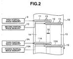
- Fig. 2 is a diagram which shows a layout example of the recording heads as to a recording sheet.
- the image recording device records an image using a plurality of color recording heads of K (black), C (cyan), M (magenta), and Y (yellow), for example.
- Fig. 2 shows two color recording heads of these. That is to say, the recording heads 11 and 12 record an image in K (black), and recording heads 11A and 12A record an image in C (cyan).
- the first recording head 11 and the second recording head 12 receive partial image data from the first partial image memory 9 and the second partial image memory 10, respectively.
- the third recording head 11A and the fourth recording head 12A receive partial image data from the third partial image memory 9A and the fourth partial image memory 10A, respectively.
- a long roll paper sheet is employed as a recording sheet 18 serving as a recording medium, which is fed in the feeding direction denoted by the reference numeral 19, for example.
- Each of the recording heads 11, 12, 11A, and 12A have a configuration wherein a plurality of recording elements 13 are arrayed in a line with approximately the same interval along the direction orthogonal to the feeding direction denoted by the reference numeral 19, i.e., the line direction.
- each recording element 13 is formed of a nozzle and so forth, for example. Note that various recording elements may be employed corresponding to the recording method.
- a recording region 14 recorded by the recording head 11 (or the recording head 11A) and a recording region 15 recorded by the recording head 12 (or the recording head 12A) are arrayed along the line direction with a head-overlapped region 16.
- Fig. 3 is a diagram which shows image data distributed by the image data distributing means 2.
- Image data 20 read out from the input image memory 1 can be classified into: image data 20a used for recording performed by the first recording head 11 alone; image data 20b used for recording performed by the second recording head 12 alone; and image data 20c used for recording performed by both the first recording head 11 and the second recording head 12.
- the first recording head 11 receives the image data 20a and the image data 20c
- the second recording head 12 receives the image data 20b and the image data 20c.
- the common image data 20c is subjected to processing for adjusting the distribution ratio, and correction processing, as described later in detail, following which the common image data 20c is supplied to the recording heads 11 and 12.
- Fig. 4 is a diagram which shows the positional relation of the first recording head and the second recording head in the head-overlapped region.
- the first recording head 11 and the second recording head 12 are disposed along the line direction so as to have a head-overlapped region OH.
- a data-overlapped region OW with a predetermined range is set in the head-overlapped region OH by the image data distribution region variation means 3.
- the image data distribution region variation means 3 sets the data-overlapped region OW including: a series of eight recording elements 13 (L1 through L8) of the first recording head 11 positioned on the left side; and a series of eight recording elements 13 (R1 through R8) of the second recording head 12 positioned on the right side, of which positions substantially match the recording elements 13 (L1 through L8), for example.
- mounting of the first recording head 11 and the second recording head 12 with generally used precision leads to deviation (phase deviation) in the line direction between the array of the recording elements 13 of the first recording head 11 and the array of the recording elements 13 of the second recording head 12.
- Fig. 4 shows generation of a phase deviation ⁇ which is a little larger than an array pitch 1, which assumes the array pitch of the recording elements 13 on the same recording head.
- phase deviation ⁇ is defined, such that in the event that ⁇ is 1, the positions of the recording elements 13 of the first recording head 11 match the positions of the recording elements 13 of the second recording head 12 in the line direction.
- the array pitch at which the recording elements 13 are arrayed is 1, and accordingly, an arrangement may be made wherein the phase deviation ⁇ is determined in any range having a width of 1, which includes the integer 1.
- the phase deviation ⁇ is determined within a range which is greater than 0.5 and is equal to or less than 1.5. It is needless to say that the present invention is not restricted to the range, rather the phase deviation ⁇ may be determined within a range which is greater than 0.3 and is equal to or less than 1.3.
- the first recording head 11 and the second recording head 12 need to be arrayed with the data-overlapped region OW with a certain length (which includes the eight recording elements 13 in the drawing), and accordingly, the first recording head 11 and the second recording head 12 are arrayed with the head-overlapped region OH so as to maintain the data-overlapped region OW, whereby the range of the phase deviation ⁇ can be determined as described above.
- Fig. 5 shows the positional relation between the recording heads mounted with the phase deviation ⁇ of 0.5 and 1.5.
- the recording elements 13 of the recording heads 11 and 12 mounted adjacent one to another are deviated along the line direction where the arrays thereof are closer than with the recording heads mounted with the phase deviation ⁇ of 1, as shown in Fig. 5(A).
- the recording elements 13 of the recording heads 11 and 12 mounted adjacent one to another are deviated along the line direction where the arrays thereof are farther away than with the recording heads mounted with the phase deviation ⁇ of 1, as shown in Fig. 5(B).
- Fig. 6 is a schematic diagram for describing a decrease and increase, due to the phase deviation ⁇ , of the image density properties in the head-overlapped region where the image data is recorded by both the adjacent recording heads.
- one recording head records image data in the data-overlapped region with a distribution ratio gradually changed such that the image density property thereof is linearly reduced along the direction as the recording head comes closer to the other recording head.
- the start point in the reduced range of one curve and the end point in the reduced region of the other curve are positioned with deviation in the direction where these points are farther away one from another, and accordingly, these image density property curves are synthesized into the image density property curve fA with the image density in the data-overlapped region being smaller than with the region other than the data-overlapped region, as shown in Fig. 6(D).
- ⁇ greater than 1 the recording heads adjacent one to another are mounted with deviation in the direction where the arrays of the recording elements thereof are farther away one from another, and accordingly, the recording heads record the image data with small ink amount per unit area.
- the start point in the reduced range of one curve and the end point in the reduced region of the other curve are positioned with deviation in the direction where these points come closer one to another, and accordingly, these image density property curves are synthesized into the image density property curve fA with image density in the data-overlapped region being greater than with the region other than the data-overlapped region, as shown in Fig. 6(F).
- ⁇ less than 1 the recording heads adjacent one to another are mounted with deviation in the direction where the arrays of the recording elements thereof come closer one to another, and accordingly, the recording heads record the image data with large ink amount per unit area.
- the recording device has a configuration wherein the image data correcting means 4 performs correction using the correction parameter F( ⁇ ) stored in the correction parameter storage means 5 so as to obtain uniform image density properties over the entire region as shown in Fig. 6(B) even in a case of ⁇ other than 1 as shown in Fig. 6(D) and Fig. 6(F).
- Fig. 7 is a diagram which shows distribution of the image data in the data-overlapped region.
- the image data of D1 through D8 which is the image data for the data-overlapped region OW is input to the image data distributing means 2 from the input image memory 1.
- the image data distributing means 2 Upon the image data distributing means 2 receiving the image data D1 through D8, the image data distributing means 2 distribute the image data of A1 through A8 to the recording elements L1 through L8 included in the data-overlapped region OW of the first recording head 11 positioned on the left side, and distribute the image data of B1 through B8 to the recording elements R1 through R8 included in the data-overlapped region OW of the second recording head 12 positioned on the right side.
- Fig. 8 is a diagram which shows how distribution of the image data is performed corresponding to setting of the image data distribution region.
- Fig. 8(A) shows image data distribution in a case wherein the image data distribution region SH is set on the left end in the data-overlapped region OW, i.e., in a case wherein the image data distribution region SH is set to a region corresponding to the recording elements L1 through L4, and the recording elements R1 through R4.
- the first partial image memory 9 stores the data thus received.
- the data thus corrected is stored in the second partial image memory 10.
- image data of the region other than the data-overlapped region OW described above is stored either in the first partial image memory 9 or the second partial image memory 10.
- Fig. 8(B) shows image data distribution in a case wherein the image data distribution region SH is set on the right end in the data-overlapped region OW, i.e., in a case wherein the image data distribution region SH is set to a region corresponding to the recording elements L5 through L8, and the recording elements R5 through R8.
- the image data correcting means 4 corrects irregularities in the image density properties which may occur in the image data distribution region SH due to the phase deviation ⁇ using the correction parameter F( ⁇ ), thereby improving the uniformity of the image.
- the present invention is not restricted to the arrangement, rather, an arrangement may be made wherein the image data correcting means 4 corrects both of the image data distributed by the image data recording means 2, and the image data distributed for the other recording head.
- Fig. 9 is a diagram which shows an example of a curve of the correction parameter F( ⁇ ) in the form of a function.
- both the low image density property in the data-overlapped region shown in Fig. 6(D) and the high image density property in the data-overlapped region shown in Fig. 6(F) are represented by W1/W ⁇ , wherein the image density property of the flat level region (region other than the data-overlapped region) is normalized by 1.
- W1 represents the distance between L0 and R8 in a case of ⁇ of 1 as shown in Fig. 4.
- W ⁇ represents the distance between L0 and R8 with actual phase deviation ⁇ .
- the image is formed of dots, and the image density property must be determined stepwise, and accordingly, the correction parameter F( ⁇ ) is determined in the form of the most suitable function by experiment.
- Fig. 9 shows an example of such practical correction parameter F( ⁇ ) dependent upon ⁇ .
- Fig. 10 shows the image data distribution regions SH each of which are determined at a random position for each line by the image data distribution region variation means 3.
- the image data distribution region SH is determined within the data-overlapped region OW.
- the layout of the image data distribution regions SH arrayed at relatively the same position in each data-overlapped region OW for all the lines may lead to conspicuous irregularities around the boundary between the adjacent partial images recorded by the recording heads 11 and 12.
- the position of the image data distribution region SH is moved within the data-overlapped region OW at random for each line, thereby making the irregularities less conspicuous around the boundary between the adjacent partial images. While it is needless to say that an arrangement according to the present embodiment without such a configuration wherein the position of the image data distribution region SH is moved at random for each line has the same advantage, an arrangement having such a configuration wherein the position of the image data distribution region SH is moved at random for each line has the particularly high advantage.
- Fig. 11 is a diagram for describing an arrangement example wherein a consideration to the quantization error is given when calculating image data based upon the image data input from the input image memory 1 for providing the image data thus calculated to the recording heads 11 and 12.
- the recording elements 13 formed on the recording heads 11 and 12 receive digital data which represents the image density corresponding to the dot position.
- the image density of each dot is controlled by adjusting the number of drops (drop number), whereby the drop number corresponds to the image density.
- Fig. 11 shows image data distribution with the recording elements 13 for recording an image with eight gray scales of the drop number of zero through the drop number of seven for each dot.
- the image density properties of the first and second recording heads 11 and 12 are adjusted such that the image density property of the first recording head 11 is gradually reduced corresponding to the gradually increased image density property of the second recording head 12 in the image data distribution region SH, and are further corrected using the correction parameter so as to smoothly connect the adjacent partial images. Accordingly, even in a case wherein integer image data (quantized values) is read out from the input image memory 1, the image data multiplied by the coefficient is not restricted to an integer. Accordingly, the image data thus obtained leads to the quantization error.
- description will be made regarding a method wherein such quantization error is not simply rounded off, but is suitably distributed to the other recording elements 13 so as to suppress the irregularities around the boundary due to the quantization error.
- the dada-overlapped region OW is formed of eight recording elements 13, and the image data distribution region SH formed of the four recording elements 13 is set on the left end within the data-overlapped region OW, as shown in Fig. 4 and Fig. 5 as described above.
- the image data A1 through A8 for the recording elements L1 through L8 forming the data-overlapped region OW of the first recording head 11, and the image data B1 through B8 for the recording elements R1 through R8 forming the data-overlapped region OW of the second recording head 12, are calculated by the image data distributing means 2 and the image data correcting means 4, as follows.
- D1 is multiplied by 0.8, and the decimal portion is truncated (i.e., quantized), whereby A1 is calculated.
- the symbol "[]” represents a function for creating the maximum integer which is equal to or less than the numerical value.
- D2 is multiplied by 0.6, and is quantized, whereby A2 is calculated.
- D3 is multiplied by 0.4, and is quantized, whereby A3 is calculated.
- D4 is multiplied by 0.2, and is quantized, whereby A4 is calculated.
- the other data is distributed to the data-overlapped region other than the image data distribution region SH.
- the image data distribution region SH is set on the left end in the data-overlapped region as shown in Fig. 11, and accordingly, all the image data is distributed to the second recording head 12.
- Fig. 12 shows an recording head unit integrated being formed of a plurality of recording heads and correction parameter storage means.
- a recording head unit 25 comprises: the first recording head 11; the second recording head 12; detecting means 24 provided to the first and second recording heads 11 and 12 for detecting the state of the first and second recording heads 11 and 12; and the correction parameter storage means 5, which are mounted on a board. Included on the end of the board are: a terminal 26a which allows transmission/reception of signals to/from the first recording head 11 and the detecting means 24 provided to the first recording head 11; a terminal 26b which allows transmission/reception of signals to/from the second recording head 12 and the detecting means 24 provided to the second recording head 12; and a terminal 26c which allows transmission/reception of signals to/from the correction parameter storage means 5.
- the detecting means 24 comprises: deviation detection sensors; temperature sensors; an acceleration sensor; a power-on detection sensor for detecting power-on operation; a mounting-position detection sensor for detecting adjustment of the mounting position; and so forth.
- the mounting-position detection sensor detects adjustment of at least one of the mounting positions of the plurality of recording heads 11 and 12.
- the power-on detection sensor detects whether or not the power is supplied to the recording heads 11 and 12. Upon the power-on detection sensor detecting that the power is supplied, the head position detection instructing means 7 instruct the head position detecting means 6 to measure the present phase deviation ⁇ .
- an arrangement may be made wherein upon the power-on detection sensor detecting that total operating time reaches a predetermined period of time from the point that the phase deviation ⁇ has been previously measured, which may be measurement at the time of manufacturing, the phase deviation ⁇ is measured, again. Furthermore, an arrangement may be made wherein upon the power-on detection sensor detecting that total non-operating time reaches a predetermined period of time from the point that the phase deviation ⁇ has been previously measured, which may be measurement at the time of manufacturing, the phase deviation ⁇ is measured, again.
- the temperature sensors measure the temperatures of the recording heads 11 and 12. It is thought that in the event that the temperature reaches a predetermined temperature, the phase deviation ⁇ changes due to thermal expansion (in the event that the temperature reaches a predetermined high temperature), or due to thermal contraction (in the event that the temperature reaches a predetermined low temperature). Accordingly, in this case, the phase deviation ⁇ is measured, again. Alternately, an arrangement may be made wherein determination is made whether or not the temperature sensors detect rapid change in temperature, i.e., detect rapid change in temperature between the recording heads 11 and 12 within a predetermined period of time, and in the event that determination has been made that the temperature sensors have detected rapid change in temperature, this arrangement measures the phase deviation ⁇ , again.
- the deviation detection sensor detects deviation of the recording heads 11 and 12, and it is thought that deviation of the recording heads 11 and 12 with a greater magnitude than with a predetermined deviation leads to change in the phase deviation ⁇ . Accordingly, in this case, this arrangement measures the phase deviation ⁇ , again.
- the acceleration sensor detects acceleration applied to the recording heads 11 and 12, and detects vibration during transport of the image recording device by truck or the like. It is thought that in the event that the acceleration sensor has detected acceleration equal to or greater than a predetermined acceleration threshold which causes great vibration (in the event that the image recording device has fallen off from the bed of the truck in transport of the image recording device, for example), the phase deviation ⁇ changes. Accordingly, in this case, this arrangement measures the phase deviation ⁇ , again.
- an arrangement may be made wherein in the event that the acceleration sensor has detected acceleration which causes vibration applied to the image recording device for a long time, even if the detected acceleration is small, (in the event that the image recording device is transported by truck or the like for a long time, for example), i.e., in the event that the arrangement detects the accumulated acceleration has reached a predetermined value from the point that the phase deviation ⁇ has been previously measured, which may be measurement at the time of manufacturing, this arrangement measures the phase deviation ⁇ , again.
- the head position detection instructing means 7 instruct the head position detecting means 6 to measure the phase deviation ⁇ , once every predetermined period of time such as: at 9:00 AM every day; on Monday every week; on the first day of every month; or the like.
- the new corresponding correction parameter F( ⁇ ) is stored in the correction parameter storage means 5, instead of the old one.
- the recording head unit 25 having such a configuration is detachably mounted on the main unit of the image recording device, and the recording head unit 25 mounted on the main unit has functions wherein image data and the detection results detected by the detecting means 24 are transmitted through the terminals 26a, 26b, and 26c.
- Each recording head unit having such an integrated configuration is formed of the recording heads arrayed adjacent one to another in the line direction as described above. with such a configuration for multicolor printing as shown in Fig. 2, each recording head unit having such an integrated configuration is formed for each color, for example.
- the correction parameter F( ⁇ ) which is property data corresponding to the phase deviation ⁇ between the recording heads arrayed adjacent one to another in the line direction is stored in the correction parameter storage means 5 mounted on the same board beforehand.
- the user replaces the recording head unit 25 including the recording head which is to be replaced, thereby having the advantage that the correction parameter is suitably replaced at the same time of mounting. This allows the user to replace the recording head unit 25 without measurement of phase deviation ⁇ .
- Fig. 13 is a diagram which shows an arrangement example wherein three recording heads are arrayed along the line direction.
- a first recording head 31, a second recording head 32, and a third recording head 33 are arrayed along the line direction at alternating positions along the sheet-feeding direction with small displacement as shown in the drawing.
- the first recording head 31 and the second recording head 32 are arrayed with a head-overlapped region OH1
- the second recording head 32 and the third recording head 33 are arrayed with a head-overlapped region OH2.
- the length of the head-overlapped region OH1 does not equal to the length of the head-overlapped region OH2, unless these recording heads are mounted in particularly high precision.
- the data-overlapped region OW1 determined within the head-overlapped region OH1 is set in the same positional relation as with the data-overlapped region OW2 determined within the head-overlapped region OH2.
- each data-overlapped region includes the same number of the recording elements 13, and accordingly, distribution of the image data by the image data distributing means 2, and correction by the image data correcting means 4, are performed using the same processing circuit and the same processing program, thereby enabling computation processing with a simple configuration.
- the image data distributing means 2 distributes the image data read out from the input image memory 1 for the first recording head 31, the second recording head 32, and the third recording head 33.
- the image data correcting means 4 corrects at least two sets of the partial image data. With the phase deviation between the first recording head 31 and the second recording head 32 as ⁇ 1, and with the phase deviation between the second recording head 32 and the third recording head 33 as ⁇ 2, in general, ⁇ 1 does not equal to ⁇ 2. Accordingly, the correction parameter storage means 5 stores the correction parameters F( ⁇ 1) and F( ⁇ 2) corresponding to the phase deviation ⁇ 1 and ⁇ 2, respectively.
- the boundary between the partial images in Y (yellow) is less conspicuous, and accordingly, the image data correcting means 4 of the circuit for performing processing of images in such color may be omitted. This reduces costs of the image recording device while maintaining acceptable image quality.
- the present invention is not restricted to the arrangement, rather, the data-overlapped region and the image data distribution region may include more recording elements, or may include less recording elements.
- the size of the region should be suitably determined giving consideration to the expressible gray scale value of image density for each dot formed by the single recording element, the pitch at which the recording elements are arrayed, and so forth.
- an arrangement wherein the image data distribution region is positioned at random for each line within the data-overlapped region, in a case of employing recording elements having properties wherein the boundary between the partial images is less conspicuous inherently, an arrangement may be made wherein the image data distribution region is fixed at the same position for each line within the data-overlapped region, or an arrangement may be made wherein the image data distribution region is arrayed at a position regularly changed for each line within the data-overlapped region.
- the present invention is not restricted to the arrangement, rather, an arrangement may be made wherein the decimal portion serving as the quantization error is distributed to the nearby pixels in the line adjacent to the present line, forward or backward, or an arrangement may be made wherein the decimal portion serving as the quantization error is distributed to the nearby pixels in both the lines adjacent to the present line, forward and backward.
- the present invention is particularly effectively applied to a full-line-type recording head formed of a combination of a plurality of recording heads so as to cover a recording width sufficient for the maximum width of the recording medium such as a recording paper sheet or the like
- the present invention is also effectively applied to the boundary between the image bands recorded by a serial-scan-type image recording device having a configuration wherein a single recording head or the like is scanned with a smaller recording width in the main-scanning direction, as well as a sub-scanning of the recording sheet in the line direction, and the combination of the main-scanning and the sub-scanning realizes recording of an image with the maximum recording width on a recording medium.
- the image recording device preferably includes discharge stabilizing means for the recording head, preliminary auxiliary means, or the like, thereby maintaining stable image density properties in a surer manner.
- discharge stabilizing means for the recording head include: capping means for the recording head; cleaning means; pressing or suctioning means; preliminary heating means formed of an electrothermal-converting member, a heating device, a combination thereof; preliminary discharge means for discharging other than recording.
- the kinds and the number of the mounted recording heads according to the present invention are not restricted in particular, rather, an arrangement may be made wherein only a single set of the recording heads is mounted corresponding to a single color ink, or an arrangement may be made wherein plural sets of the recording heads are mounted corresponding to plural kinds of inks each of which has a kind of a color and a density different one from another.
- the present invention is markedly effectively applied not only to an image recording device having a monochromatic recording mode for recording an image only in a single color such as black or the like, but also to an image recording device having at least one of: a full-color image recording mode by an integrated recording head having a configuration wherein different kinds of inks each of which has a color and a density different one from another are mixed before printing; and a full-color image recording mode by a combination of a plurality of recording heads corresponding to various colors and densities different one from another.
- an ink having properties of solidifying at room temperature or less, and melting or liquefying by heating to room temperature or more may be employed, as well as an ink having properties of serving as a liquid at room temperature.
- an arrangement may be made wherein the temperature of the ink is suitably adjusted.
- the image recording head using such an ink having properties of serving as a solid in a normal situation and liquefying by heating has the advantage of preventing evaporation of the ink.
- the present invention can be also applied to an arrangement using an ink having properties of serving as a liquid during ink discharge according to recording signals, and beginning to solidify at the time of reaching the recording medium.
- the image recording devices include: a printer used as a image output terminal for an information processing apparatus such as a computer or the like; a photocopier in combination with a scanner or the like; a facsimile having transmission/reception functions; and so forth.
- the image recording device has the advantage of suppressing irregularities in image density around the boundary between partial images due to phase deviation between arrays of the recording heads arrayed adjacent one to another, each of which is formed of recording elements, thereby obtaining high-quality images.
- the image recording device has the advantage of suppressing irregularities in image density around the boundary between partial images due to phase deviation between arrays of the recording heads arrayed adjacent one to another, each of which is formed of recording elements, thereby obtaining high-quality images.
Landscapes
- Physics & Mathematics (AREA)
- General Physics & Mathematics (AREA)
- Health & Medical Sciences (AREA)
- General Health & Medical Sciences (AREA)
- Toxicology (AREA)
- Engineering & Computer Science (AREA)
- Quality & Reliability (AREA)
- Microelectronics & Electronic Packaging (AREA)
- Optics & Photonics (AREA)
- Ink Jet (AREA)
- Electronic Switches (AREA)
- Printers Or Recording Devices Using Electromagnetic And Radiation Means (AREA)
Abstract
Description
Claims (19)
- An image recording device for recording an image formed of pixels, in units of a line based upon image data, comprising:a plurality of recording heads formed of a plurality of recording elements cyclically arrayed along the line direction, which are continuously arrayed adjacent one to another in the line direction with head-overlapped regions included in array regions formed of the recording elements arrayed along the line direction;image data distributing means for distributing the image data to the plurality of recording heads;image data distribution region setting means for setting in the head-overlapped regions an image data distribution region formed of a series of one or more recording elements by the image data distribution means, the image data distribution region constituting a region where the image data of each pixel, is distributed to both of the two recording heads arrayed adjacent one to another;correction parameter storage means for storing a correction parameter corresponding to phase deviation between the cyclic arrays each of which are included in the two recording heads arrayed adjacent one to another, for correcting difference, which can be generated when there is the phase deviation, in recording image density properties between the recording elements included in the image data distribution region and the recording elements not included in the image data distribution region; andimage data correcting means for correcting image data for the image data distribution region based upon the correction parameter stored in the correction parameter storage means.
- An image recording device according to Claim 1, wherein the image data distribution region setting means sets a data-overlapped region, wherein the image data of each pixel can be distributed to both of the two recording heads arrayed adjacent one to another, within the head-overlapped region, and sets for each line a position of the image data distribution region so as to be deviated to the line direction within the data-overlapped region.
- An image recording device according to Claim 2, wherein the three or more recording heads are included,
and wherein all the data-overlapped regions included in the two or more head-overlapped regions are determined substantially with the same length along the line direction. - An image recording device according to Claim 1, wherein the image data distributing means distribute image data with a distribution ratio for each pixel gradually changed from one side to the other side of the array of the recording elements forming the image data distribution region.
- An image recording device according to Claim 1, wherein the plurality of recording heads and the correction parameter storage means form a single unit, which allows the user to replace the recording heads without separating one from another.
- An image recording device according to Claim 1, further including head position detecting means for measuring the positional relation between the recording elements included in the data-overlapped region so as to obtain the phase deviation.
- An image recording device according to Claim 1, further including:test-pattern creating means for creating a test pattern for measuring the state of the array of the recording elements included in the recording head; andhead position detecting means for measuring the positional relation between the pixels recorded by the recording elements included in the data-overlapped region in an image recorded based upon the test pattern created by the test-pattern creating means so as to obtain the phase deviation.
- An image recording device according to Claim 6 or Claim 7, further including head position detection instructing means for instructing the head position detecting means to detect the phase deviation at appropriate timing,
wherein in the event that the new phase deviation is obtained according to instructions from the head position detection instructing means, the correction parameter storage means store the correction parameter corresponding to the new phase deviation. - An image recording device according to Claim 8, the timing is a timing wherein the user adjusts at least one mounting position of the plurality of recording heads.
- An image recording device according to Claim 8, wherein the timing is a timing wherein non-operating time of the image recording device reaches a predetermined period of time from a point of previous timing when there is the previous timing, or a timing wherein non-operating time of the image recording device accumulated from the point of manufacturing reaches a predetermined period of time when there is not the previous timing.
- An image recording device according to Claim 8, wherein the timing is a timing wherein operating time of the image recording device reaches a predetermined period of time from a point of previous timing when there is the previous timing, or a timing wherein operating time of the image recording device accumulated from the point of manufacturing reaches a predetermined period of time when there is not the previous timing.
- An image recording device according to Claim 8, wherein the timing is once every predetermined time.
- An image recording device according to Claim 8, wherein the timing is a timing wherein the user turns on the power supply of the image recording device.
- An image recording device according to Claim 8, wherein the timing is a timing wherein change in the temperature of the recording head exhibits a predetermined value within a predetermined period of time.
- An image recording device according to Claim 8,
wherein the timing is a timing wherein the temperature of the recording head reaches a predetermined temperature. - An image recording device according to Claim 8, further including a deviation detection sensor mounted on the recording head for detecting deviation of the recording head,
wherein the timing is a timing wherein the deviation detection sensor detects deviation of the recording head equal to or greater than a predetermined value. - An image recording device according to Claim 8, further including an acceleration sensor mounted on the recording head for detecting at least whether or not acceleration equal to or greater than a predetermined value is applied to the recording head,
wherein the timing is a timing wherein the acceleration sensor detects acceleration equal to or greater than the predetermined value. - An image recording device according to Claim 8, further including an acceleration sensor mounted on the recording head for detecting acceleration applied to the recording head,
wherein the timing is a timing wherein the accumulated value detected by the acceleration sensor reaches a predetermined value from the point of previous measurement when there is the previous timing, or a timing wherein the accumulated value detected by the acceleration sensor reaches a predetermined value from the point of manufacturing. - An image recording device according to Claim 1, wherein the image data correcting means corrects a quantization error occurred in correction of image data of at least one pixel in the image data distribution region when correcting image data of other pixels in the neighborhood.
Applications Claiming Priority (3)
| Application Number | Priority Date | Filing Date | Title |
|---|---|---|---|
| JP2002091938 | 2002-03-28 | ||
| JP2002091938A JP2003285434A (en) | 2002-03-28 | 2002-03-28 | Image recording device |
| PCT/JP2003/003849 WO2003082578A1 (en) | 2002-03-28 | 2003-03-27 | Image recording apparatus |
Publications (2)
| Publication Number | Publication Date |
|---|---|
| EP1488926A1 true EP1488926A1 (en) | 2004-12-22 |
| EP1488926A4 EP1488926A4 (en) | 2009-09-16 |
Family
ID=28671691
Family Applications (1)
| Application Number | Title | Priority Date | Filing Date |
|---|---|---|---|
| EP03715526A Withdrawn EP1488926A4 (en) | 2002-03-28 | 2003-03-27 | Image recording apparatus |
Country Status (7)
| Country | Link |
|---|---|
| US (1) | US20050174374A1 (en) |
| EP (1) | EP1488926A4 (en) |
| JP (1) | JP2003285434A (en) |
| KR (1) | KR100592840B1 (en) |
| CN (1) | CN100391737C (en) |
| TW (1) | TWI256242B (en) |
| WO (1) | WO2003082578A1 (en) |
Cited By (2)
| Publication number | Priority date | Publication date | Assignee | Title |
|---|---|---|---|---|
| CN101264690B (en) * | 2007-03-17 | 2011-03-02 | 株式会社理光 | Image forming apparatus, landing position shift correction method, and landing position shift correction sheet member |
| EP4312153A1 (en) * | 2022-07-27 | 2024-01-31 | Konica Minolta, Inc. | Image forming apparatus, control method for image forming apparatus, and control program for image forming apparatus |
Families Citing this family (26)
| Publication number | Priority date | Publication date | Assignee | Title |
|---|---|---|---|---|
| JP4626272B2 (en) * | 2004-11-10 | 2011-02-02 | 富士ゼロックス株式会社 | Image forming apparatus |
| JP4708870B2 (en) | 2005-06-09 | 2011-06-22 | キヤノン株式会社 | Ink jet recording head, ink jet recording apparatus, and method of manufacturing ink jet recording head |
| JP4632247B2 (en) * | 2005-07-14 | 2011-02-16 | キヤノンファインテック株式会社 | Recording apparatus and registration adjustment method |
| JP5193422B2 (en) * | 2005-12-15 | 2013-05-08 | 理想科学工業株式会社 | Recording density adjustment method for image recording apparatus |
| JP5013712B2 (en) * | 2005-12-28 | 2012-08-29 | キヤノン株式会社 | Inkjet recording apparatus and inkjet recording method |
| JP5213317B2 (en) * | 2006-08-22 | 2013-06-19 | キヤノン株式会社 | Inkjet recording apparatus and inkjet recording method |
| JP5205736B2 (en) * | 2006-10-10 | 2013-06-05 | 富士ゼロックス株式会社 | Exposure equipment |
| JP5125666B2 (en) * | 2008-03-25 | 2013-01-23 | セイコーエプソン株式会社 | Liquid ejection device |
| JP2010105289A (en) * | 2008-10-30 | 2010-05-13 | Seiko Epson Corp | Fluid jet apparatus and fluid jet method |
| JP5365393B2 (en) | 2008-11-28 | 2013-12-11 | セイコーエプソン株式会社 | Printing apparatus, printing method, and program |
| JP2010131855A (en) * | 2008-12-04 | 2010-06-17 | Seiko Epson Corp | Image processing apparatus, image processing method, and image forming apparatus |
| JP2010149329A (en) * | 2008-12-24 | 2010-07-08 | Seiko Epson Corp | Method for manufacturing fluid jetting apparatus and method for setting correction value for fluid jetting apparatus |
| JP5675072B2 (en) * | 2009-08-20 | 2015-02-25 | キヤノン株式会社 | Information processing apparatus, information processing method, and program |
| JP2011062991A (en) * | 2009-09-18 | 2011-03-31 | Seiko Epson Corp | Liquid injecting apparatus |
| US8322811B2 (en) * | 2009-12-17 | 2012-12-04 | Ricoh Production Print Solutions LLC | Multi-pass calibration in fixed printhead array printers |
| JP5511362B2 (en) * | 2009-12-22 | 2014-06-04 | キヤノン株式会社 | Data generating apparatus and data generating method |
| JP5661366B2 (en) * | 2010-07-30 | 2015-01-28 | キヤノン株式会社 | Image processing apparatus and image processing method |
| JP5296825B2 (en) * | 2011-03-29 | 2013-09-25 | 富士フイルム株式会社 | Recording position error measuring apparatus and method, image forming apparatus and method, and program |
| JP5361085B2 (en) * | 2011-03-29 | 2013-12-04 | 富士フイルム株式会社 | Defect recording element detection apparatus and method, image forming apparatus and method, and program |
| CN102765254B (en) * | 2012-08-10 | 2014-11-05 | 李支斌 | Phase different electronic calibration system of multiple-spray-head printing spray points |
| US9880795B2 (en) * | 2012-12-04 | 2018-01-30 | Canon Finetech Nisca, Inc. | Recording system, recording apparatus, information processing apparatus, and recording control method that shift range of recording elements |
| DE102013003689A1 (en) * | 2013-03-04 | 2014-09-04 | Heidelberger Druckmaschinen Ag | A method for producing a composite of sections printed image on a substrate with two inkjet printheads |
| JP6377003B2 (en) | 2015-03-26 | 2018-08-22 | シチズン時計株式会社 | Thermal transfer printer and control method thereof |
| US9908324B1 (en) * | 2017-02-27 | 2018-03-06 | Eastman Kodak Company | Printing with overlapping printheads |
| JP7818968B2 (en) * | 2022-01-25 | 2026-02-24 | キヤノン株式会社 | Image processing device, image processing method, and program |
| EP4670976A1 (en) | 2024-06-28 | 2025-12-31 | Riso Kagaku Corporation | METHOD AND DEVICE FOR CONTROLLING LIQUID DISCHARGE |
Family Cites Families (16)
| Publication number | Priority date | Publication date | Assignee | Title |
|---|---|---|---|---|
| JP2713728B2 (en) * | 1988-05-12 | 1998-02-16 | キヤノン株式会社 | Liquid jet recording device |
| US4977410A (en) * | 1989-09-14 | 1990-12-11 | Seiko Instruments Inc. | Thermal line printer with staggered head segments and overlap compensation |
| JPH05183738A (en) * | 1992-01-07 | 1993-07-23 | Canon Inc | Image processing device |
| JP2725243B2 (en) | 1992-07-23 | 1998-03-11 | 長野木田工業株式会社 | Mushroom cultivation method and cap used for it |
| CA2113960C (en) * | 1993-01-29 | 2001-07-31 | Kazuyoshi Takahashi | Image supply apparatus, image output apparatus, control apparatus therefor, and image forming system having these apparatuses |
| US5818492A (en) * | 1994-05-12 | 1998-10-06 | Minnesota Mining And Manufacturing Company | Method and system for thermal graphic printing |
| US6247784B1 (en) * | 1995-09-08 | 2001-06-19 | Canon Kabushiki Kaisha | Ink jet cartridge replacement control |
| JPH09138472A (en) * | 1995-11-13 | 1997-05-27 | Konica Corp | Image recording device |
| JPH10272804A (en) * | 1997-03-28 | 1998-10-13 | Minolta Co Ltd | Optical writing device and image forming device |
| JPH11207948A (en) * | 1997-11-14 | 1999-08-03 | Canon Inc | Recording apparatus and recording control method |
| JP4298836B2 (en) * | 1998-06-30 | 2009-07-22 | 東芝テック株式会社 | Inkjet recording device |
| JP3102429B2 (en) * | 1998-08-27 | 2000-10-23 | セイコーエプソン株式会社 | Printing apparatus and printing method |
| JP2000190484A (en) * | 1998-12-24 | 2000-07-11 | Toshiba Tec Corp | Line recording head |
| JP3384376B2 (en) * | 1999-02-10 | 2003-03-10 | セイコーエプソン株式会社 | Adjustment of printing position deviation during printing using head identification information of print head unit |
| JP4019654B2 (en) * | 2000-05-29 | 2007-12-12 | 富士ゼロックス株式会社 | Image forming apparatus |
| US6655771B2 (en) * | 2000-06-27 | 2003-12-02 | Fuji Photo Film Co., Ltd. | Head position detecting method, recording head, image recording apparatus and storage medium |
-
2002
- 2002-03-28 JP JP2002091938A patent/JP2003285434A/en active Pending
-
2003
- 2003-03-26 TW TW092106750A patent/TWI256242B/en not_active IP Right Cessation
- 2003-03-27 CN CNB038066734A patent/CN100391737C/en not_active Expired - Fee Related
- 2003-03-27 KR KR1020047013737A patent/KR100592840B1/en not_active Expired - Fee Related
- 2003-03-27 US US10/508,380 patent/US20050174374A1/en not_active Abandoned
- 2003-03-27 EP EP03715526A patent/EP1488926A4/en not_active Withdrawn
- 2003-03-27 WO PCT/JP2003/003849 patent/WO2003082578A1/en not_active Ceased
Cited By (2)
| Publication number | Priority date | Publication date | Assignee | Title |
|---|---|---|---|---|
| CN101264690B (en) * | 2007-03-17 | 2011-03-02 | 株式会社理光 | Image forming apparatus, landing position shift correction method, and landing position shift correction sheet member |
| EP4312153A1 (en) * | 2022-07-27 | 2024-01-31 | Konica Minolta, Inc. | Image forming apparatus, control method for image forming apparatus, and control program for image forming apparatus |
Also Published As
| Publication number | Publication date |
|---|---|
| TWI256242B (en) | 2006-06-01 |
| CN100391737C (en) | 2008-06-04 |
| CN1642740A (en) | 2005-07-20 |
| JP2003285434A (en) | 2003-10-07 |
| EP1488926A4 (en) | 2009-09-16 |
| KR100592840B1 (en) | 2006-06-28 |
| US20050174374A1 (en) | 2005-08-11 |
| WO2003082578A1 (en) | 2003-10-09 |
| TW200306740A (en) | 2003-11-16 |
| KR20040099294A (en) | 2004-11-26 |
Similar Documents
| Publication | Publication Date | Title |
|---|---|---|
| US20050174374A1 (en) | Image recording apparatus | |
| US8626623B2 (en) | Image processing apparatus, image processing method, and recording medium | |
| US8960834B2 (en) | Inkjet printing apparatus using print head with overlapping nozzle arrays | |
| JP4306214B2 (en) | Misalignment correction during bidirectional printing according to the platen gap | |
| US7494204B2 (en) | Correction of paper feed error during interlace printing using a representative correction value | |
| US8011756B2 (en) | Imaging method and inkjet recording apparatus | |
| US7874634B2 (en) | Image forming apparatus and image forming method | |
| EP0876920B1 (en) | Dot printing with partial double scanning of raster lines | |
| US8388092B2 (en) | Image forming apparatus and image forming method | |
| US7593132B2 (en) | Method for calibrating printing of lenticular images to lenticular media | |
| US20120243005A1 (en) | Ink jet recording apparatus and recording method | |
| JP3982211B2 (en) | Correction of paper feed error in printer | |
| US7198343B2 (en) | Image printing apparatus | |
| JP5352951B2 (en) | Droplet ejection device, control method for droplet ejection device, and control program for droplet ejection device | |
| EP2324623B1 (en) | Image processing apparatus, image processing method, and computer program product | |
| JP6171289B2 (en) | Image processing method, image processing apparatus, and program | |
| JP3921965B2 (en) | Correction of paper feed error in printer with interlaced recording mode | |
| US7264326B2 (en) | Inkjet printer | |
| JP3921966B2 (en) | Correction of paper feed error in printer | |
| JP3876654B2 (en) | Correction of paper feed error in printer | |
| JP2004050498A (en) | INK JET RECORDING APPARATUS, INK JET RECORDING METHOD, AND INK JET RECORDING PROGRAM | |
| JP2002019091A (en) | Printing that compensates for changes in the image due to low ink levels | |
| US8941844B2 (en) | Image processing apparatus and image processing method for suppressing image degradation caused by a printing position fluctuation | |
| JP2004154950A (en) | Image recorder | |
| EP0732841A2 (en) | Halftone recording method and apparatus |
Legal Events
| Date | Code | Title | Description |
|---|---|---|---|
| PUAI | Public reference made under article 153(3) epc to a published international application that has entered the european phase |
Free format text: ORIGINAL CODE: 0009012 |
|
| 17P | Request for examination filed |
Effective date: 20040921 |
|
| AK | Designated contracting states |
Kind code of ref document: A1 Designated state(s): AT BE BG CH CY CZ DE DK EE ES FI FR GB GR HU IE IT LI LU MC NL PT RO SE SI SK TR |
|
| RIN1 | Information on inventor provided before grant (corrected) |
Inventor name: TATSUTA, SEIJI Inventor name: EBIHARA, TOSHIYUKI Inventor name: KOMIYA, YASUHIRO Inventor name: IOKA, KEN |
|
| A4 | Supplementary search report drawn up and despatched |
Effective date: 20090813 |
|
| RIC1 | Information provided on ipc code assigned before grant |
Ipc: B41J 2/155 20060101AFI20090807BHEP Ipc: B41J 2/515 20060101ALI20031015BHEP Ipc: B41J 2/447 20060101ALI20031015BHEP |
|
| STAA | Information on the status of an ep patent application or granted ep patent |
Free format text: STATUS: THE APPLICATION HAS BEEN WITHDRAWN |
|
| 18W | Application withdrawn |
Effective date: 20091007 |