EP1487278B1 - A method and device for cutting objects into fixed portions - Google Patents
A method and device for cutting objects into fixed portions Download PDFInfo
- Publication number
- EP1487278B1 EP1487278B1 EP20030744973 EP03744973A EP1487278B1 EP 1487278 B1 EP1487278 B1 EP 1487278B1 EP 20030744973 EP20030744973 EP 20030744973 EP 03744973 A EP03744973 A EP 03744973A EP 1487278 B1 EP1487278 B1 EP 1487278B1
- Authority
- EP
- European Patent Office
- Prior art keywords
- mould
- cutting
- objects
- pressure
- portion size
- Prior art date
- Legal status (The legal status is an assumption and is not a legal conclusion. Google has not performed a legal analysis and makes no representation as to the accuracy of the status listed.)
- Expired - Lifetime
Links
Images



Classifications
-
- A—HUMAN NECESSITIES
- A22—BUTCHERING; MEAT TREATMENT; PROCESSING POULTRY OR FISH
- A22C—PROCESSING MEAT, POULTRY, OR FISH
- A22C21/00—Processing poultry
- A22C21/0023—Dividing poultry
-
- A—HUMAN NECESSITIES
- A22—BUTCHERING; MEAT TREATMENT; PROCESSING POULTRY OR FISH
- A22C—PROCESSING MEAT, POULTRY, OR FISH
- A22C7/00—Apparatus for pounding, forming, or pressing meat, sausage-meat, or meat products
- A22C7/0023—Pressing means
- A22C7/003—Meat-moulds
-
- B—PERFORMING OPERATIONS; TRANSPORTING
- B26—HAND CUTTING TOOLS; CUTTING; SEVERING
- B26D—CUTTING; DETAILS COMMON TO MACHINES FOR PERFORATING, PUNCHING, CUTTING-OUT, STAMPING-OUT OR SEVERING
- B26D3/00—Cutting work characterised by the nature of the cut made; Apparatus therefor
- B26D3/28—Splitting layers from work; Mutually separating layers by cutting
-
- B—PERFORMING OPERATIONS; TRANSPORTING
- B26—HAND CUTTING TOOLS; CUTTING; SEVERING
- B26D—CUTTING; DETAILS COMMON TO MACHINES FOR PERFORATING, PUNCHING, CUTTING-OUT, STAMPING-OUT OR SEVERING
- B26D7/00—Details of apparatus for cutting, cutting-out, stamping-out, punching, perforating, or severing by means other than cutting
- B26D7/01—Means for holding or positioning work
- B26D7/018—Holding the work by suction
-
- B—PERFORMING OPERATIONS; TRANSPORTING
- B26—HAND CUTTING TOOLS; CUTTING; SEVERING
- B26D—CUTTING; DETAILS COMMON TO MACHINES FOR PERFORATING, PUNCHING, CUTTING-OUT, STAMPING-OUT OR SEVERING
- B26D7/00—Details of apparatus for cutting, cutting-out, stamping-out, punching, perforating, or severing by means other than cutting
- B26D7/01—Means for holding or positioning work
- B26D7/02—Means for holding or positioning work with clamping means
-
- B—PERFORMING OPERATIONS; TRANSPORTING
- B26—HAND CUTTING TOOLS; CUTTING; SEVERING
- B26D—CUTTING; DETAILS COMMON TO MACHINES FOR PERFORATING, PUNCHING, CUTTING-OUT, STAMPING-OUT OR SEVERING
- B26D2210/00—Machines or methods used for cutting special materials
- B26D2210/02—Machines or methods used for cutting special materials for cutting food products, e.g. food slicers
- B26D2210/04—Machines or methods used for cutting special materials for cutting food products, e.g. food slicers controlling the volume by pressing the food product, e.g. meat to a predetermined shape before cutting
-
- Y—GENERAL TAGGING OF NEW TECHNOLOGICAL DEVELOPMENTS; GENERAL TAGGING OF CROSS-SECTIONAL TECHNOLOGIES SPANNING OVER SEVERAL SECTIONS OF THE IPC; TECHNICAL SUBJECTS COVERED BY FORMER USPC CROSS-REFERENCE ART COLLECTIONS [XRACs] AND DIGESTS
- Y10—TECHNICAL SUBJECTS COVERED BY FORMER USPC
- Y10T—TECHNICAL SUBJECTS COVERED BY FORMER US CLASSIFICATION
- Y10T83/00—Cutting
- Y10T83/04—Processes
-
- Y—GENERAL TAGGING OF NEW TECHNOLOGICAL DEVELOPMENTS; GENERAL TAGGING OF CROSS-SECTIONAL TECHNOLOGIES SPANNING OVER SEVERAL SECTIONS OF THE IPC; TECHNICAL SUBJECTS COVERED BY FORMER USPC CROSS-REFERENCE ART COLLECTIONS [XRACs] AND DIGESTS
- Y10—TECHNICAL SUBJECTS COVERED BY FORMER USPC
- Y10T—TECHNICAL SUBJECTS COVERED BY FORMER US CLASSIFICATION
- Y10T83/00—Cutting
- Y10T83/929—Tool or tool with support
- Y10T83/9411—Cutting couple type
- Y10T83/9423—Punching tool
- Y10T83/9428—Shear-type male tool
Definitions
- the present invention relates to a method and a device for cutting objects into fixed portions.
- raw materials are sold in predetermined portions, typically on the bases of weight and/or the shape of the raw material.
- the weight and the shape of a single product is of crucial importance. This is for example the case when the product is a chicken breast, especially when the final product is as an example a chicken sandwich or chicken burger.
- This industry is growing extremely fast, and the demand for chicken breasts with a fixed shape and weight increases. Mainly three methods are used when processing chicken breasts for this purpose:
- GB2304025A discloses a method and an apparatus for trimming meat e.g. chicken fillets to produce portions substantially of the same weight.
- the meat is placed in an open cavity which is mounted on a conveyor.
- the meat is then urged into the cavity and skewers are driven into the meat to secure it in place.
- the conveyor then delivers the meat to a trimming station where a cutting blade trims away the exposed surface of the meat and the meat trimming are collected.
- the trimmed meat is released from the receptacle at a release station by the withdrawal of the skewers.
- the invention relates to a device for cutting objects into fixed portion size with a predetermined shape comprising:
- the mould is an upper part of a housing, said housing additionally comprising a base unit as a bottom part with at least one passage extending through it as an entrance for under pressure.
- the mould may be opened and/or closed and/or is replaceable, which simplifies as an example the cleaning procedure or when the portion size is to be changed.
- An interior between the upper and lower part of the housing is provided as well as at least one channel extending through the mould towards the interior. Therefore, by applying under-pressure the effect will be in the whole interior between the mould and the bottom part of the housing. At least one channel extending through the mould towards the interior ensures therefore that the under pressure is transferred to the mould and situates the object in a fixed position.
- the base unit is provided with a plurality of supporting means, such as pins extending perpendicular from the base unit towards the upper part of the housing, for supporting the mould (the upper part) and preventing it from collapsing due to the under pressure.
- the device further comprises means for transferring the mould in a uniform motion during the cutting process, and wherein a cutting blade is positioned adjacent to the surface of the mould is provided adapted to perform a cut parallel to the surface of the mould.
- Vacuum pump, air duct or similar means can be used as an under pressure means, wherein a nozzle connected to said under pressure means is preferably positioned adjacent to the at least one passage in the base unit.
- the mould is one unit provided with at least one passage extending through it.
- This passage may be an open channel extending through the mould and perpendicular to the surface of the mould for transferring the under pressure to the surface of the mould.
- the essential feature in present invention is to provide an under pressure for situating the products in a fixed position and subsequently cut the object as described above.
- the under pressure in the moulds may be provided through different implementations, such as by connecting each mould to said means for providing under pressure.
- a productive portioning device apparatus By mounting a plurality of moulds to a conveying unit in a continuous way a productive portioning device apparatus is formed, wherein the objects are cut into fixed portions with a fixed shape while the objects are being transferred in a uniform motion.
- the upper part of the conveying units may be defined as the processing part, where the objects are processed, and the lower part as the idle part.
- the cutting means may be a cutting blade, such as a rotating blade, positioned adjacent to the processing part of the conveying means. Other types of cutting means can be used.
- the processing part of the conveyer belt is fed with objects to be processed, which may be done manually, and the moving objects are situated in a fixed position in the mould through the under pressure as they pass the cutting blade, they are cut in a manner so that only the part filling the mould remains in the mould and the part of the object extending over the mould is removed.
- the remaining part in the mould has therefore a fixed weight and shape.
- an additional means is provided for situated above the processing part for maintaining the object in a fixed position while it is being cut. This is to prevent a failure in the cutting, which could occur if for example the object does not fully cover the mould, which could cause an air leak to the surface of the mould and therefore reduce the under pressure at the surface of the mould.
- This additional means may be additional conveying unit with a conveyer belt, where a part the belt is pressed against the upper part of the object while said object is being cut and thereby preventing said leak to the surface of the mould. This is however not an essential part in the present invention.
- the conveyor unit may as well be without said additional means.
- a removing board adapted to remove the cut part of the object is mounted to the conveying unit, wherein said removed parts are transferred to a position where further processing is continued. If the removed parts are above minimum weight/size for an additional portion, they may be reprocessed, i.e. the process described here above may be repeated for those parts. The parts that however are under the minimum weight/size for such reprocess are used for other products, such as nuggets.
- the present invention relates to a method for cutting objects into fixed portion size with a predetermined shape, said method comprising:
- the cutting is performed parallel to the surface of the mould so that the portion size corresponds to the size of the object that fills out the mould and the portion shape to the shape of the mould.
- the object is a chicken breast.
- Other types of products are also possible, such as meat and any types of poultry items.
- Figure 1 shows a housing 1 with a mould 4, wherein the mould defines the shape of the part of the object to be cut.
- the object can be different kind of food items, such as chicken breast, turkey breast, meat etc.
- the housing is divided into two sections. This first section is a base unit 3 with a passage extending through it 6 and a plurality of supporting pins 22 or supporting means, which will be referred to later, and the mould 4 with a plurality of open channels 32 extending through it, said mould defining the shape and size of the portion to be cut. Both the size and the shape of the mould may be varied, depending on the product and the portion to be cut.
- the mould is mounted to the base unit through a hinge system 5 so that it may be opened, closed or removed.
- This two-part form of the housing i.e. the base unit 3 and the mould 4 is not essential. A one part for of the housing is also possible.
- a groove 7, of a similar shape as the mould 4, is formed into the base unit 3, and also a slot 60 or sealing the mould 4 and the base unit 3, wherein a plastic material as an example may be used as a seal material.
- a plastic material as an example may be used as a seal material.
- the supporting pins 22 act as a supporting means for the mould 4 and prevents it from collapsing due to the under pressure.
- the under-pressure provided through the passage 6 is distributed within this interior and transferred through open channels 32 to the surface of the mould 4, preferably equally, and is not solely focused to the part of the mould that is adjacent to the passage 6 when the housing is in a closed position.
- the object can now be cut.
- the cut is performed parallel to the plane of the housing 1 so that the part of the object extending over the mould 4 is removed and the remaining part of the object is solely the part filling the mould and defined by the space 4.
- the cut part must not be regarded as a waste.
- the cut part can either be reprocessed if it is above the weight/size of one portion. If not, it may be used for other products such as chicken nuggets as an example.
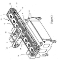
- Figure 2 illustrates one embodiment of a conveyor supported by a frame 11 with a two chains 25 provided with a plurality of pins (not shown), adapted to slide into said engaging means of the housing 1 and therefore mounting the housing between the two chains as shown in Fig.2.
- Other mounting methods are inherent possible for mounting housing such the one shown in Fig. 1 to a conveyor system.
- a conveyor unit By mounting a plurality of housings 1 in the way as described above a conveyor unit is defined forming an single endless loop, which may be driven in a revolving manner by a driving unit 16 in a direction indicated by the arrow 14.
- the upper part of the conveyor unit may be defined as a processing part 12, which is the part where the object is situated in the mould 4 and cut, and the lower section part as a idle part 13. Between the processing part 12 and the idle part 13 is nozzle 31 connected to vacuum pump (see Fig. 5), or similar means for obtaining under-pressure in at least one mould. Any other kind of means for providing such under pressure could also be used.
- the under-pressure is therefore provided in the moulds that are positioned directly above the under pressure means 37(see Fig. 6).
- a cutting means 8 is positioned adjacent to the processing part 12, where the under-pressure is high and the objects situated in a fixed position.
- a rotatable cutting blade 10 is extended between two wheels 9, 15 and positioned adjacent to the plane of the housing 1 and used for cutting the part oft the object extending over the mould.
- an additional means 26 situated above the processing part may be provided for maintaining the object in a fixed position while it is being cut. This is to prevent a failure in the cutting, which could occur if for example the object does not fully cover the mould 4 so that air leaks to the surface of the mould and reduces therefore the under pressure at the surface of the mould.
- This may be additional conveying unit (only the supporting frame is shown) with a conveyer belt, where a part the belt is pressed against the upper part of the object while said object is being cut and thereby preventing said leak to the surface of the mould.
- This is however not an essential part in the present invention.
- the conveyor unit in Fig. 2 may as well be without said means 26.
- the cutting is performed while the objects are moving in a uniform motion in the direction indicated by the arrow 14.
- the objects passing by the cutting blade are cut in a manner so that only the part filling the mould 4 remains in the mould.
- the conveyor unit forms an endless loop with a two, or more side by side arranged housings 1, and not a single housing 1 as shown in Fig. 2.
- Figure 3 shows a side view of a housing as shown in Fig. 1, with an object, such as chicken breast.
- the part of the object that defines the fixed portion and shape 18 is the part that fills out the mould 4, and the remaining part of the object 19 is the part that will be removed.
- Shown is the interior in-between said base unit and said mould.
- An under-pressure P1 20 (where P1 ⁇ P2) is provided through the passage 6 and is distributed within said interior so that the whole object will be situated in the mould 4 in a fixed position.
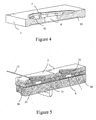
- Figure 4 shows the cross section of the base 3 unit of the housing 1, with the supporting pins 22 for supporting the mould 4 (not shown), the groove 7 of a similar shape as the mould 4, the vertical passage 6 and a horizontal passage 30 that is coupled to the passage 6.
- Fig. 5 shows a cross sectional part of two housings 2 from Fig. 2 as well as the rotating cutting blade 10 and the plurality open channels 32 extending through the mould for transferring the under pressure in said interior to the surface of the mould.
- a supporting means 35 on which the plurality of housings rest 1 is shown, wherein said supporting means is mounted to the supporting frame 11 as shown in Fig. 2.
- An under pressure nozzle 31 extends through said supporting means 35 and is positioned adjacent to the horizontal passage 30 in a fixed position.
- a sealing 36 adapted to maintain the vacuum is preferably arranged between the housings 1 and the supporting means 35.
- Figure 6 shows a side view of the conveyor unit in Fig. 2, illustrating the moving direction of the housings 1 (moulds 4), the cutting blade 10, the driving unit 16 for the conveyor unit, a vacuum pump 37, or similar means for providing under pressure, and air nozzle 31 connected to the said means for providing under pressure, the supporting means 35 for supporting said plurality of housings 1 and said chains 25.
- Figure 7 shows a front view of the apparatus in Fig. 2 and Fig. 6, showing the cutting blade 10, the housing 1 and the base unit 3, the supporting means 35 and the sealing 36.
Landscapes
- Engineering & Computer Science (AREA)
- Life Sciences & Earth Sciences (AREA)
- Forests & Forestry (AREA)
- Mechanical Engineering (AREA)
- Zoology (AREA)
- Food Science & Technology (AREA)
- Wood Science & Technology (AREA)
- Processing Of Meat And Fish (AREA)
- Meat, Egg Or Seafood Products (AREA)
- Mechanical Treatment Of Semiconductor (AREA)
- Crushing And Pulverization Processes (AREA)
- Details Of Cutting Devices (AREA)
- Turning (AREA)
- Perforating, Stamping-Out Or Severing By Means Other Than Cutting (AREA)
Abstract
Description
- The present invention relates to a method and a device for cutting objects into fixed portions.
- It is well known that raw materials are sold in predetermined portions, typically on the bases of weight and/or the shape of the raw material. For some products the weight and the shape of a single product is of crucial importance. This is for example the case when the product is a chicken breast, especially when the final product is as an example a chicken sandwich or chicken burger. This industry is growing extremely fast, and the demand for chicken breasts with a fixed shape and weight increases. Mainly three methods are used when processing chicken breasts for this purpose:
- a) Delivering the product directly to the customer without processing it further. Obviously this has the disadvantage that the pieces have different shapes as well as weight, as only a little part of the chicken breasts have the "right" weight and shape that fulfils the need set forth by the customer.
- b) Manual processing of the chicken breast, which comprises cutting each peace in a fixed portion into a predetermined shape. This is however inaccurate method and requires a lot of manpower, which is expensive, as well as the shape of the final product has the tendency to be unnatural.
- c) Automation processing, where the processing is based on two steps:
- i) providing a horizontal cut, thereby ensuring a right thickness of the product, and subsequently
- ii) providing a vertical cut so that side parts of the breast are removed, by means of moving a cutting means, which is a high pressurised water jet, in a predefined path, defining thereby in-plane shape of the chicken breast.
- The problem with this latter method is how expensive it is, manpower demanding and requires very extensive mechanical maintenance as well as know how. Also, the shape of the final product is not natural.
-
GB2304025A - Accordingly, there is a urgent need for a low cost method that requires limited manpower and know how, and wherein the shape of the final product is as natural in shape as possible.
- It is an object of the present invention to provide a simple, cost effective device and method for cutting objects such as chicken breast into portions with a fixed shape and weight where the natural shape of the object is conserved.
- According to the first aspect the invention relates to a device for cutting objects into fixed portion size with a predetermined shape comprising:
- a plurality of moulds mounted on a conveying means, wherein upper part of said conveying means forms a processing part, and lower half of said conveying means forms an idle part,
- means for feeding said processing part with objects to be processed, wherein said objects are situated in said moulds,
means for cutting said objects into an object part corresponding to the mould, and a supplementary part corresponding to the part of said object extending above the mould positioned adjacent to said processing part, wherein the object part has a fixed portion size, - means for providing under-pressure in the mould for positioning said objects in a fixed position as they pass the cutting means, and
means for transferring said mould in a uniform motion during the cutting process, means for removing said supplementary part of said objects mounted to said processing part of said conveyor, - In one preferred embodiment the mould is an upper part of a housing, said housing additionally comprising a base unit as a bottom part with at least one passage extending through it as an entrance for under pressure. Preferably the mould may be opened and/or closed and/or is replaceable, which simplifies as an example the cleaning procedure or when the portion size is to be changed. An interior between the upper and lower part of the housing is provided as well as at least one channel extending through the mould towards the interior. Therefore, by applying under-pressure the effect will be in the whole interior between the mould and the bottom part of the housing. At least one channel extending through the mould towards the interior ensures therefore that the under pressure is transferred to the mould and situates the object in a fixed position. In this preferred embodiment the base unit is provided with a plurality of supporting means, such as pins extending perpendicular from the base unit towards the upper part of the housing, for supporting the mould (the upper part) and preventing it from collapsing due to the under pressure. In one preferred embodiment the device further comprises means for transferring the mould in a uniform motion during the cutting process, and wherein a cutting blade is positioned adjacent to the surface of the mould is provided adapted to perform a cut parallel to the surface of the mould.
- Vacuum pump, air duct or similar means can be used as an under pressure means, wherein a nozzle connected to said under pressure means is preferably positioned adjacent to the at least one passage in the base unit.
- In another embodiment the mould is one unit provided with at least one passage extending through it. This passage may be an open channel extending through the mould and perpendicular to the surface of the mould for transferring the under pressure to the surface of the mould. The essential feature in present invention is to provide an under pressure for situating the products in a fixed position and subsequently cut the object as described above.
- The under pressure in the moulds may be provided through different implementations, such as by connecting each mould to said means for providing under pressure.
- By mounting a plurality of moulds to a conveying unit in a continuous way a productive portioning device apparatus is formed, wherein the objects are cut into fixed portions with a fixed shape while the objects are being transferred in a uniform motion. The upper part of the conveying units may be defined as the processing part, where the objects are processed, and the lower part as the idle part. The cutting means may be a cutting blade, such as a rotating blade, positioned adjacent to the processing part of the conveying means. Other types of cutting means can be used. Accordingly, as the processing part of the conveyer belt is fed with objects to be processed, which may be done manually, and the moving objects are situated in a fixed position in the mould through the under pressure as they pass the cutting blade, they are cut in a manner so that only the part filling the mould remains in the mould and the part of the object extending over the mould is removed. The remaining part in the mould has therefore a fixed weight and shape.
- In one embodiment an additional means is provided for situated above the processing part for maintaining the object in a fixed position while it is being cut. This is to prevent a failure in the cutting, which could occur if for example the object does not fully cover the mould, which could cause an air leak to the surface of the mould and therefore reduce the under pressure at the surface of the mould. This additional means may be additional conveying unit with a conveyer belt, where a part the belt is pressed against the upper part of the object while said object is being cut and thereby preventing said leak to the surface of the mould. This is however not an essential part in the present invention. The conveyor unit may as well be without said additional means.
- Preferably, a removing board adapted to remove the cut part of the object is mounted to the conveying unit, wherein said removed parts are transferred to a position where further processing is continued. If the removed parts are above minimum weight/size for an additional portion, they may be reprocessed, i.e. the process described here above may be repeated for those parts. The parts that however are under the minimum weight/size for such reprocess are used for other products, such as nuggets.
- In a second aspect the present invention relates to a method for cutting objects into fixed portion size with a predetermined shape, said method comprising:
- situating said objects in a mould,
- applying under-pressure in said mould for positioning said object in a fixed position as they pass the cutting means" and
- transferring said mould in a uniform motion during the cutting process,
- cutting said object into an object part and a supplementary part,
- remove said supplementary part of said objects,
- Preferably, the cutting is performed parallel to the surface of the mould so that the portion size corresponds to the size of the object that fills out the mould and the portion shape to the shape of the mould. In one embodiment the object is a chicken breast. Other types of products are also possible, such as meat and any types of poultry items.
- In the following the present invention, and in particular preferred embodiments thereof, will be described in greater details in connection with the accompanying drawings in which
- Figure 1 shows a mould defining a shape of the object to be cut,
- Figure 2 shows a plurality of moulds mounted to a conveying means,
- Figure 3 shows a side view of a mould with an object to be cut,
- Figure 4 shows the cross section of the base unit of the housing,
- Figure 5 shows a cross sectional part of two housings from Fig. 2,
- Figure 6 shows a side view of the conveyor unit in Fig. 2, and
- Figure 7 shows a front view of the apparatus in Fig. 2 and Fig. 6.
- Figure 1 shows a
housing 1 with amould 4, wherein the mould defines the shape of the part of the object to be cut. The object can be different kind of food items, such as chicken breast, turkey breast, meat etc. In a preferred embodiment the housing is divided into two sections. This first section is abase unit 3 with a passage extending through it 6 and a plurality of supportingpins 22 or supporting means, which will be referred to later, and themould 4 with a plurality ofopen channels 32 extending through it, said mould defining the shape and size of the portion to be cut. Both the size and the shape of the mould may be varied, depending on the product and the portion to be cut. In this preferred embodiment the mould is mounted to the base unit through ahinge system 5 so that it may be opened, closed or removed. This has the advantage that cleaning of the mould is more effective and the mould can easily be exchanged, if for example the portion to be cut is changed. This two-part form of the housing, i.e. thebase unit 3 and themould 4 is not essential. A one part for of the housing is also possible. - A
groove 7, of a similar shape as themould 4, is formed into thebase unit 3, and also aslot 60 or sealing themould 4 and thebase unit 3, wherein a plastic material as an example may be used as a seal material. This is important when a under pressure is provided in preventing an air leak into the interior between themould 4 and the base unit. When the housing is in a closed position the object is placed in themould 4, preferably so that the object covers the whole mould. By providing an under-pressure, which can for example be done through vacuum pump, or an air duct the object is in a fixed position and fills out themould 4. In this position the part of the object to be cut defines a fixed portion of fixed weight. This weight is determined from the mass density multiplied with the volume of the mould, assuming the mass density is constant. In a closed position, the supportingpins 22 act as a supporting means for themould 4 and prevents it from collapsing due to the under pressure. Between themould 4 and thebase unit 3 is an interior. Therefore, the under-pressure provided through thepassage 6 is distributed within this interior and transferred throughopen channels 32 to the surface of themould 4, preferably equally, and is not solely focused to the part of the mould that is adjacent to thepassage 6 when the housing is in a closed position. - The object can now be cut. The cut is performed parallel to the plane of the
housing 1 so that the part of the object extending over themould 4 is removed and the remaining part of the object is solely the part filling the mould and defined by thespace 4. The cut part must not be regarded as a waste. In the case that the object is a chicken breast, the cut part can either be reprocessed if it is above the weight/size of one portion. If not, it may be used for other products such as chicken nuggets as an example. - Shown is also engaging
means 23, for mounting a plurality of such housing to a conveyor, as shown in Fig. 2. - Figure 2 illustrates one embodiment of a conveyor supported by a
frame 11 with a twochains 25 provided with a plurality of pins (not shown), adapted to slide into said engaging means of thehousing 1 and therefore mounting the housing between the two chains as shown in Fig.2. Other mounting methods are inherent possible for mounting housing such the one shown in Fig. 1 to a conveyor system. - By mounting a plurality of
housings 1 in the way as described above a conveyor unit is defined forming an single endless loop, which may be driven in a revolving manner by a drivingunit 16 in a direction indicated by thearrow 14. - The upper part of the conveyor unit may be defined as a
processing part 12, which is the part where the object is situated in themould 4 and cut, and the lower section part as aidle part 13. Between theprocessing part 12 and theidle part 13 isnozzle 31 connected to vacuum pump (see Fig. 5), or similar means for obtaining under-pressure in at least one mould. Any other kind of means for providing such under pressure could also be used. The under-pressure is therefore provided in the moulds that are positioned directly above the under pressure means 37(see Fig. 6). - A cutting means 8 is positioned adjacent to the
processing part 12, where the under-pressure is high and the objects situated in a fixed position. Arotatable cutting blade 10 is extended between twowheels housing 1 and used for cutting the part oft the object extending over the mould. In this embodiment an additional means 26 situated above the processing part may be provided for maintaining the object in a fixed position while it is being cut. This is to prevent a failure in the cutting, which could occur if for example the object does not fully cover themould 4 so that air leaks to the surface of the mould and reduces therefore the under pressure at the surface of the mould. This may be additional conveying unit (only the supporting frame is shown) with a conveyer belt, where a part the belt is pressed against the upper part of the object while said object is being cut and thereby preventing said leak to the surface of the mould. This is however not an essential part in the present invention. The conveyor unit in Fig. 2 may as well be without said means 26. - The cutting is performed while the objects are moving in a uniform motion in the direction indicated by the
arrow 14. The objects passing by the cutting blade are cut in a manner so that only the part filling themould 4 remains in the mould. - In anther embodiment, the conveyor unit forms an endless loop with a two, or more side by side arranged
housings 1, and not asingle housing 1 as shown in Fig. 2. - Figure 3 shows a side view of a housing as shown in Fig. 1, with an object, such as chicken breast. The part of the object that defines the fixed portion and
shape 18 is the part that fills out themould 4, and the remaining part of theobject 19 is the part that will be removed. Shown is the interior in-between said base unit and said mould. An under-pressure P1 20 (where P1<P2) is provided through thepassage 6 and is distributed within said interior so that the whole object will be situated in themould 4 in a fixed position. By moving thehousing 1 in the direction indicated by thearrow 14, similar as shown in Fig. 2, and passing the mould a cutting means 10, which may be a cutting blade, the part of the object extending themould 4 will be removed. - Figure 4 shows the cross section of the
base 3 unit of thehousing 1, with the supportingpins 22 for supporting the mould 4 (not shown), thegroove 7 of a similar shape as themould 4, thevertical passage 6 and ahorizontal passage 30 that is coupled to thepassage 6. This is illustrated in a more detailed in Fig. 5 showing a cross sectional part of twohousings 2 from Fig. 2 as well as therotating cutting blade 10 and the pluralityopen channels 32 extending through the mould for transferring the under pressure in said interior to the surface of the mould. A supportingmeans 35, on which the plurality of housings rest 1 is shown, wherein said supporting means is mounted to the supportingframe 11 as shown in Fig. 2. An underpressure nozzle 31 extends through said supporting means 35 and is positioned adjacent to thehorizontal passage 30 in a fixed position. Accordingly, as the conveyor unit is running and the plurality of housings 1 (moulds 4) are moving in a uniform motion the under pressure in each mould is maintained while thehorizontal passage 30 is adjacent to thenozzle 31. If the velocity of the conveyor unit is V, and the length of thehorizontal passage 30 is L, the time where the under pressure is maintained in the mould is t=V/L. A sealing 36 adapted to maintain the vacuum is preferably arranged between thehousings 1 and the supportingmeans 35. - Figure 6 shows a side view of the conveyor unit in Fig. 2, illustrating the moving direction of the housings 1 (moulds 4), the
cutting blade 10, the drivingunit 16 for the conveyor unit, avacuum pump 37, or similar means for providing under pressure, andair nozzle 31 connected to the said means for providing under pressure, the supportingmeans 35 for supporting said plurality ofhousings 1 and saidchains 25. - Figure 7 shows a front view of the apparatus in Fig. 2 and Fig. 6, showing the
cutting blade 10, thehousing 1 and thebase unit 3, the supportingmeans 35 and the sealing 36.
Claims (20)
- A device for cutting objects into fixed portion size with a predetermined shape comprising:• a plurality of moulds (4) mounted on a conveying means (25), wherein upper part of said conveying means forms a processing part (12), and lower half of said conveying means forms an idle part (13),• means for feeding said processing part with objects to be processed, wherein said objects are situated in said moulds (4),
means for cutting (10) said objects into an object part (18) corresponding to the mould, and a supplementary part (19) corresponding to the part of said object extending above the mould positioned adjacent to said processing part (12), wherein the object part has a fixed portion size,• means for providing under-pressure (37) in the mould for positioning said objects in a fixed position as they pass the cutting means (8), andwherein said objects part (18) has a fixed portion size with a predetermined shape corresponding to the shape of the mould and the supplementary part (19) corresponds to the difference between the object size and the portion size of the object.
means for transferring (16) said mould in a uniform motion during the cutting process, means for removing said supplementary part of said objects mounted to said processing part of said conveyor, - A device according to claim 1, wherein the mould (4) forms an upper part of a housing (1), said housing additionally comprising a base unit (3) as a bottom part of the housing (1) with at least one passage (6) extending through it.
- A device according to claim 1 or 2, wherein the mould may be opened and/or closed and/or is replaceable.
- A device according to any of the preceding claims, wherein the base unit is provided with a supporting means (35) extending perpendicular from the base unit towards the upper part of the housing acting as a supporting means for the mould.
- A device according to any of the preceding claims, wherein the cutting means (8) is a cutting blade (10).
- A device according to any of the preceding claims, wherein the cutting blade (10) is positioned adjacent to the surface of the mould (4) and is adapted to perform a cut parallel to the surface of the mould (4).
- A device according to any of the preceding claims, wherein the mould (4) is provided with at least one open channel (6) extending through the mould (4) and perpendicular to the surface of the mould (4) for transferring the under pressure (37) to the surface of the mould (4).
- A device according to any of the preceding claims, wherein the mould (4) is a single unit.
- A device according to any of the preceding claims, wherein the cutting means (8) is a rotatable cutting blade (10).
- A device according to any of the preceding claims, wherein the means for providing under-pressure (37) is an air duct.
- A device according to any of the preceding claims, wherein the means for providing under-pressure (37) is a vacuum pump.
- A device according to any of the preceding claims, wherein the means for providing the under-pressure (37) is positioned between the upper-and lower section parts of the conveying means.
- A device according to any of the preceding claims, wherein a nozzle (31) connected to the means for providing the under pressure (37) is positioned adjacent to the processing part (12) between the processing part and the idle part (13) of the conveying means (25).
- A device according to any of the preceding claims, wherein a removing board is adapted to remove the cut part (19) of the object is mounted to the conveying means.
- A device according to any of the preceding claims, wherein a removing means adapted to guide the removed parts of the object from the conveying unit to a location where the cut parts (19) are further processed is mounted to the conveying means.
- A method for cutting objects into fixed portion size with a predetermined shape, said method comprising:• situating said objects in a mould (4),• applying under-pressure (37) in said mould for positioning said object in a fixed position as they pass the cutting means (10), and• transferring (16) said mould in a uniform motion during the cutting process,• cutting said object into an object part (18) and a supplementary part (19),• remove said supplementary part (19) of said objects,wherein said object part (18) has a fixed portion size with a predetermined shape and said supplementary part (19) corresponds to the difference between the object size and the portion size of the object.
- A method according to claim 16, wherein the portion size corresponds to the size of the object that fills out the mould.
- A method according to claim 16 or 17, wherein the portion shape corresponds to the shape of the mould.
- A method according to any of the claims 16 - 18, wherein the object is a chicken breast.
- A method according to any of the claims 16 - 19, wherein the cutting is performed parallel to the surface of the mould.
Applications Claiming Priority (3)
| Application Number | Priority Date | Filing Date | Title |
|---|---|---|---|
| IS6321 | 2002-03-21 | ||
| IS632102 | 2002-03-21 | ||
| PCT/IS2003/000014 WO2003079801A1 (en) | 2002-03-21 | 2003-03-21 | A method and device for cutting objects into fixed portions |
Publications (2)
| Publication Number | Publication Date |
|---|---|
| EP1487278A1 EP1487278A1 (en) | 2004-12-22 |
| EP1487278B1 true EP1487278B1 (en) | 2007-10-24 |
Family
ID=36701266
Family Applications (1)
| Application Number | Title | Priority Date | Filing Date |
|---|---|---|---|
| EP20030744973 Expired - Lifetime EP1487278B1 (en) | 2002-03-21 | 2003-03-21 | A method and device for cutting objects into fixed portions |
Country Status (12)
| Country | Link |
|---|---|
| US (1) | US20060027060A1 (en) |
| EP (1) | EP1487278B1 (en) |
| CN (1) | CN100518520C (en) |
| AT (1) | ATE376359T1 (en) |
| AU (1) | AU2003215886B2 (en) |
| BR (1) | BR0308593A (en) |
| CA (1) | CA2479796C (en) |
| DE (1) | DE60317052T2 (en) |
| DK (1) | DK1487278T3 (en) |
| ES (1) | ES2295610T3 (en) |
| IS (1) | IS2901B (en) |
| WO (1) | WO2003079801A1 (en) |
Families Citing this family (11)
| Publication number | Priority date | Publication date | Assignee | Title |
|---|---|---|---|---|
| US20090075579A1 (en) * | 2004-11-16 | 2009-03-19 | Scanvaegt International A/S | cutting apparatus |
| WO2006080033A1 (en) * | 2005-01-25 | 2006-08-03 | Marel Hf. | A method and apparatus for cutting objects into fixed portions |
| US20090047886A1 (en) * | 2007-08-17 | 2009-02-19 | O'neil John J | Cutlet cutter |
| CN101606547A (en) * | 2009-07-03 | 2009-12-23 | 吴碧峰 | A kind of cutting device for rice field eels |
| DE102010019589A1 (en) | 2010-05-05 | 2011-11-10 | Ferdinand Nock | Cutting device set for machines for cutting slices of meat, has motor unit that drives over chain drive of feed belt which is loaded by operator and conveys product for blade shaft |
| US20130337135A1 (en) * | 2012-06-13 | 2013-12-19 | Michael F. Vieira | Apparatuses for producing food products from fish and chicken shims and associated systems and methods |
| TWM549124U (en) * | 2016-02-24 | 2017-09-21 | 耐克創新有限合夥公司 | Vacuum-assisted cutting tool and welding system using the same |
| CN105851192B (en) * | 2016-05-25 | 2017-09-22 | 济南好为尔机械有限公司 | A kind of die cutter |
| KR102350859B1 (en) * | 2019-09-23 | 2022-01-13 | 지대호 | Automatic cutting device of chicken meat |
| CN113940371A (en) * | 2021-11-20 | 2022-01-18 | 溆浦县龙潭天然食品有限公司 | Preserved meat processing full-automatic slitter with prevent empting structure |
| CN118452255B (en) * | 2024-07-15 | 2024-09-20 | 济南翰科机械有限公司 | Block-type meat intelligent processing device |
Family Cites Families (8)
| Publication number | Priority date | Publication date | Assignee | Title |
|---|---|---|---|---|
| US2221436A (en) * | 1939-09-02 | 1940-11-12 | Joseph F Remington | Skiving machine |
| DD296832A5 (en) * | 1989-12-22 | 1991-12-19 | Volkswerft Gmbh Stralsund,De | DEVICE FOR FIXING MATERIALS IN ACTUATORS, PREFERABLY FOR PRESSURE FLUID LENSES |
| WO1992019110A1 (en) * | 1991-05-07 | 1992-11-12 | Promofinn Oy | Method for cutting meat or equivalent into required cuttings |
| DE4333534A1 (en) * | 1993-10-01 | 1995-04-06 | Andreas Kronawitter | Method and device for removing bones from fish fillets |
| GB9516256D0 (en) * | 1995-08-08 | 1995-10-11 | Moy Park Ltd | Method and apparatus for trimming meat |
| DE19834524A1 (en) * | 1998-07-31 | 2000-02-10 | Nordischer Maschinenbau | Device or method for processing meat |
| US6797296B2 (en) * | 2000-12-28 | 2004-09-28 | Stoelting, Llc | Food product portioning |
| US7040976B2 (en) * | 2004-06-08 | 2006-05-09 | Nienstedt Gmbh | Method of portioning meat |
-
2003
- 2003-03-21 ES ES03744973T patent/ES2295610T3/en not_active Expired - Lifetime
- 2003-03-21 WO PCT/IS2003/000014 patent/WO2003079801A1/en not_active Ceased
- 2003-03-21 DE DE2003617052 patent/DE60317052T2/en not_active Expired - Lifetime
- 2003-03-21 CA CA 2479796 patent/CA2479796C/en not_active Expired - Lifetime
- 2003-03-21 DK DK03744973T patent/DK1487278T3/en active
- 2003-03-21 US US10/508,623 patent/US20060027060A1/en not_active Abandoned
- 2003-03-21 BR BR0308593A patent/BR0308593A/en not_active IP Right Cessation
- 2003-03-21 CN CNB038109670A patent/CN100518520C/en not_active Expired - Lifetime
- 2003-03-21 AT AT03744973T patent/ATE376359T1/en not_active IP Right Cessation
- 2003-03-21 EP EP20030744973 patent/EP1487278B1/en not_active Expired - Lifetime
- 2003-03-21 AU AU2003215886A patent/AU2003215886B2/en not_active Ceased
-
2004
- 2004-10-14 IS IS7503A patent/IS2901B/en unknown
Also Published As
| Publication number | Publication date |
|---|---|
| IS2901B (en) | 2014-10-15 |
| AU2003215886A1 (en) | 2003-10-08 |
| ATE376359T1 (en) | 2007-11-15 |
| WO2003079801A1 (en) | 2003-10-02 |
| EP1487278A1 (en) | 2004-12-22 |
| DE60317052D1 (en) | 2007-12-06 |
| IS7503A (en) | 2004-10-14 |
| CN100518520C (en) | 2009-07-29 |
| DK1487278T3 (en) | 2008-03-03 |
| AU2003215886B2 (en) | 2009-04-23 |
| BR0308593A (en) | 2005-02-01 |
| CN1652689A (en) | 2005-08-10 |
| CA2479796C (en) | 2011-01-18 |
| CA2479796A1 (en) | 2003-10-02 |
| ES2295610T3 (en) | 2008-04-16 |
| DE60317052T2 (en) | 2008-07-31 |
| US20060027060A1 (en) | 2006-02-09 |
Similar Documents
| Publication | Publication Date | Title |
|---|---|---|
| CA2479796C (en) | A method and device for cutting objects into fixed portions | |
| CA2338947C (en) | Device and method for processing meat | |
| JP4447810B2 (en) | Insert sheet supply device for cold cut slicer | |
| US20090035434A1 (en) | Method and Apparatus for Cutting Objects into Fixed Portions | |
| US12075791B2 (en) | Paper interleaver | |
| KR101786622B1 (en) | Meat dicer | |
| EP2777897B1 (en) | Industrial slicer | |
| US20100031791A1 (en) | Portioning of food stuff | |
| US4941379A (en) | Apparatus for producing sized controlled portions of meat | |
| US7455517B2 (en) | Apparatus for proportioning meat product for packaging | |
| EP1436127A1 (en) | Device and method for cutting meat | |
| JP5648228B2 (en) | Meat slicer and meat slice method | |
| US3675272A (en) | Method of cutting and packing poultry | |
| CN210551396U (en) | Strip processor for the production of jerky | |
| CN213674287U (en) | Dicing device for meat product processing | |
| CN210929408U (en) | Meat stringing and cutting machine | |
| US20040265454A1 (en) | Method and apparatus for forming a shaped meat product | |
| JPH0779607B2 (en) | Foreign body removal device for meat | |
| CN118716390B (en) | Automatic poultry carcass segmentation equipment and segmentation method thereof | |
| CN206967564U (en) | Double of cutter device of chicken nugget | |
| JPH0929119A (en) | Method for cutting meat block, device for cutting meat block and molding pallet used for cutting meat block | |
| BR102020024425B1 (en) | IRREGULAR SHAPE SMOKED PORK PIECES SLICER | |
| CN121421021A (en) | Meat food section device | |
| CN118716390A (en) | A poultry carcass automatic cutting device and cutting method thereof | |
| EP1765087A1 (en) | Method for moulding a raw material supplied as a mass into separate products |
Legal Events
| Date | Code | Title | Description |
|---|---|---|---|
| PUAI | Public reference made under article 153(3) epc to a published international application that has entered the european phase |
Free format text: ORIGINAL CODE: 0009012 |
|
| 17P | Request for examination filed |
Effective date: 20041019 |
|
| AK | Designated contracting states |
Kind code of ref document: A1 Designated state(s): AT BE BG CH CY CZ DE DK EE ES FI FR GB GR HU IE IT LI LU MC NL PT RO SE SI SK TR |
|
| AX | Request for extension of the european patent |
Extension state: AL LT LV MK |
|
| 17Q | First examination report despatched |
Effective date: 20051026 |
|
| RIC1 | Information provided on ipc code assigned before grant |
Ipc: B26D 7/01 20060101ALI20061213BHEP Ipc: A22C 17/02 20060101AFI20061213BHEP Ipc: A22C 21/00 20060101ALI20061213BHEP |
|
| GRAP | Despatch of communication of intention to grant a patent |
Free format text: ORIGINAL CODE: EPIDOSNIGR1 |
|
| GRAS | Grant fee paid |
Free format text: ORIGINAL CODE: EPIDOSNIGR3 |
|
| GRAA | (expected) grant |
Free format text: ORIGINAL CODE: 0009210 |
|
| AK | Designated contracting states |
Kind code of ref document: B1 Designated state(s): AT BE BG CH CY CZ DE DK EE ES FI FR GB GR HU IE IT LI LU MC NL PT RO SE SI SK TR |
|
| REG | Reference to a national code |
Ref country code: GB Ref legal event code: FG4D |
|
| REG | Reference to a national code |
Ref country code: CH Ref legal event code: EP |
|
| REG | Reference to a national code |
Ref country code: IE Ref legal event code: FG4D |
|
| REF | Corresponds to: |
Ref document number: 60317052 Country of ref document: DE Date of ref document: 20071206 Kind code of ref document: P |
|
| REG | Reference to a national code |
Ref country code: DK Ref legal event code: T3 |
|
| REG | Reference to a national code |
Ref country code: ES Ref legal event code: FG2A Ref document number: 2295610 Country of ref document: ES Kind code of ref document: T3 |
|
| PG25 | Lapsed in a contracting state [announced via postgrant information from national office to epo] |
Ref country code: CH Free format text: LAPSE BECAUSE OF FAILURE TO SUBMIT A TRANSLATION OF THE DESCRIPTION OR TO PAY THE FEE WITHIN THE PRESCRIBED TIME-LIMIT Effective date: 20071024 Ref country code: LI Free format text: LAPSE BECAUSE OF FAILURE TO SUBMIT A TRANSLATION OF THE DESCRIPTION OR TO PAY THE FEE WITHIN THE PRESCRIBED TIME-LIMIT Effective date: 20071024 Ref country code: SE Free format text: LAPSE BECAUSE OF FAILURE TO SUBMIT A TRANSLATION OF THE DESCRIPTION OR TO PAY THE FEE WITHIN THE PRESCRIBED TIME-LIMIT Effective date: 20080124 |
|
| REG | Reference to a national code |
Ref country code: CH Ref legal event code: PL |
|
| PG25 | Lapsed in a contracting state [announced via postgrant information from national office to epo] |
Ref country code: PT Free format text: LAPSE BECAUSE OF FAILURE TO SUBMIT A TRANSLATION OF THE DESCRIPTION OR TO PAY THE FEE WITHIN THE PRESCRIBED TIME-LIMIT Effective date: 20080324 Ref country code: BG Free format text: LAPSE BECAUSE OF FAILURE TO SUBMIT A TRANSLATION OF THE DESCRIPTION OR TO PAY THE FEE WITHIN THE PRESCRIBED TIME-LIMIT Effective date: 20080124 Ref country code: SI Free format text: LAPSE BECAUSE OF FAILURE TO SUBMIT A TRANSLATION OF THE DESCRIPTION OR TO PAY THE FEE WITHIN THE PRESCRIBED TIME-LIMIT Effective date: 20071024 |
|
| PG25 | Lapsed in a contracting state [announced via postgrant information from national office to epo] |
Ref country code: AT Free format text: LAPSE BECAUSE OF FAILURE TO SUBMIT A TRANSLATION OF THE DESCRIPTION OR TO PAY THE FEE WITHIN THE PRESCRIBED TIME-LIMIT Effective date: 20071024 |
|
| ET | Fr: translation filed | ||
| PG25 | Lapsed in a contracting state [announced via postgrant information from national office to epo] |
Ref country code: CZ Free format text: LAPSE BECAUSE OF FAILURE TO SUBMIT A TRANSLATION OF THE DESCRIPTION OR TO PAY THE FEE WITHIN THE PRESCRIBED TIME-LIMIT Effective date: 20071024 |
|
| PG25 | Lapsed in a contracting state [announced via postgrant information from national office to epo] |
Ref country code: RO Free format text: LAPSE BECAUSE OF FAILURE TO SUBMIT A TRANSLATION OF THE DESCRIPTION OR TO PAY THE FEE WITHIN THE PRESCRIBED TIME-LIMIT Effective date: 20071024 |
|
| PLBE | No opposition filed within time limit |
Free format text: ORIGINAL CODE: 0009261 |
|
| STAA | Information on the status of an ep patent application or granted ep patent |
Free format text: STATUS: NO OPPOSITION FILED WITHIN TIME LIMIT |
|
| 26N | No opposition filed |
Effective date: 20080725 |
|
| PG25 | Lapsed in a contracting state [announced via postgrant information from national office to epo] |
Ref country code: MC Free format text: LAPSE BECAUSE OF NON-PAYMENT OF DUE FEES Effective date: 20080331 |
|
| PG25 | Lapsed in a contracting state [announced via postgrant information from national office to epo] |
Ref country code: EE Free format text: LAPSE BECAUSE OF FAILURE TO SUBMIT A TRANSLATION OF THE DESCRIPTION OR TO PAY THE FEE WITHIN THE PRESCRIBED TIME-LIMIT Effective date: 20071024 Ref country code: GR Free format text: LAPSE BECAUSE OF FAILURE TO SUBMIT A TRANSLATION OF THE DESCRIPTION OR TO PAY THE FEE WITHIN THE PRESCRIBED TIME-LIMIT Effective date: 20080125 Ref country code: IE Free format text: LAPSE BECAUSE OF NON-PAYMENT OF DUE FEES Effective date: 20080321 |
|
| PG25 | Lapsed in a contracting state [announced via postgrant information from national office to epo] |
Ref country code: FI Free format text: LAPSE BECAUSE OF FAILURE TO SUBMIT A TRANSLATION OF THE DESCRIPTION OR TO PAY THE FEE WITHIN THE PRESCRIBED TIME-LIMIT Effective date: 20071024 |
|
| PG25 | Lapsed in a contracting state [announced via postgrant information from national office to epo] |
Ref country code: CY Free format text: LAPSE BECAUSE OF FAILURE TO SUBMIT A TRANSLATION OF THE DESCRIPTION OR TO PAY THE FEE WITHIN THE PRESCRIBED TIME-LIMIT Effective date: 20071024 |
|
| PG25 | Lapsed in a contracting state [announced via postgrant information from national office to epo] |
Ref country code: LU Free format text: LAPSE BECAUSE OF NON-PAYMENT OF DUE FEES Effective date: 20080321 Ref country code: HU Free format text: LAPSE BECAUSE OF FAILURE TO SUBMIT A TRANSLATION OF THE DESCRIPTION OR TO PAY THE FEE WITHIN THE PRESCRIBED TIME-LIMIT Effective date: 20080425 |
|
| PG25 | Lapsed in a contracting state [announced via postgrant information from national office to epo] |
Ref country code: TR Free format text: LAPSE BECAUSE OF FAILURE TO SUBMIT A TRANSLATION OF THE DESCRIPTION OR TO PAY THE FEE WITHIN THE PRESCRIBED TIME-LIMIT Effective date: 20071024 |
|
| PGFP | Annual fee paid to national office [announced via postgrant information from national office to epo] |
Ref country code: DK Payment date: 20140321 Year of fee payment: 12 Ref country code: NL Payment date: 20140314 Year of fee payment: 12 |
|
| PGFP | Annual fee paid to national office [announced via postgrant information from national office to epo] |
Ref country code: ES Payment date: 20140326 Year of fee payment: 12 Ref country code: IT Payment date: 20140312 Year of fee payment: 12 |
|
| PGFP | Annual fee paid to national office [announced via postgrant information from national office to epo] |
Ref country code: FR Payment date: 20140331 Year of fee payment: 12 |
|
| PGFP | Annual fee paid to national office [announced via postgrant information from national office to epo] |
Ref country code: SK Payment date: 20150310 Year of fee payment: 13 |
|
| REG | Reference to a national code |
Ref country code: DK Ref legal event code: EBP Effective date: 20150331 |
|
| REG | Reference to a national code |
Ref country code: NL Ref legal event code: MM Effective date: 20150401 |
|
| PG25 | Lapsed in a contracting state [announced via postgrant information from national office to epo] |
Ref country code: IT Free format text: LAPSE BECAUSE OF NON-PAYMENT OF DUE FEES Effective date: 20150321 |
|
| REG | Reference to a national code |
Ref country code: FR Ref legal event code: ST Effective date: 20151130 |
|
| PG25 | Lapsed in a contracting state [announced via postgrant information from national office to epo] |
Ref country code: FR Free format text: LAPSE BECAUSE OF NON-PAYMENT OF DUE FEES Effective date: 20150331 |
|
| REG | Reference to a national code |
Ref country code: ES Ref legal event code: FD2A Effective date: 20160427 |
|
| PG25 | Lapsed in a contracting state [announced via postgrant information from national office to epo] |
Ref country code: DK Free format text: LAPSE BECAUSE OF NON-PAYMENT OF DUE FEES Effective date: 20150331 |
|
| PG25 | Lapsed in a contracting state [announced via postgrant information from national office to epo] |
Ref country code: ES Free format text: LAPSE BECAUSE OF NON-PAYMENT OF DUE FEES Effective date: 20150322 |
|
| REG | Reference to a national code |
Ref country code: SK Ref legal event code: MM4A Ref document number: E 2735 Country of ref document: SK Effective date: 20160321 |
|
| PG25 | Lapsed in a contracting state [announced via postgrant information from national office to epo] |
Ref country code: SK Free format text: LAPSE BECAUSE OF NON-PAYMENT OF DUE FEES Effective date: 20160321 |
|
| PG25 | Lapsed in a contracting state [announced via postgrant information from national office to epo] |
Ref country code: NL Free format text: LAPSE BECAUSE OF NON-PAYMENT OF DUE FEES Effective date: 20150401 |
|
| PGFP | Annual fee paid to national office [announced via postgrant information from national office to epo] |
Ref country code: GB Payment date: 20220225 Year of fee payment: 20 Ref country code: DE Payment date: 20220217 Year of fee payment: 20 |
|
| PGFP | Annual fee paid to national office [announced via postgrant information from national office to epo] |
Ref country code: BE Payment date: 20220217 Year of fee payment: 20 |
|
| REG | Reference to a national code |
Ref country code: DE Ref legal event code: R071 Ref document number: 60317052 Country of ref document: DE |
|
| REG | Reference to a national code |
Ref country code: BE Ref legal event code: MK Effective date: 20230321 |
|
| REG | Reference to a national code |
Ref country code: GB Ref legal event code: PE20 Expiry date: 20230320 |
|
| PG25 | Lapsed in a contracting state [announced via postgrant information from national office to epo] |
Ref country code: GB Free format text: LAPSE BECAUSE OF EXPIRATION OF PROTECTION Effective date: 20230320 |