EP1486966A2 - Data recording / reproducing apparatus and method using needle-shaped member - Google Patents
Data recording / reproducing apparatus and method using needle-shaped member Download PDFInfo
- Publication number
- EP1486966A2 EP1486966A2 EP04013728A EP04013728A EP1486966A2 EP 1486966 A2 EP1486966 A2 EP 1486966A2 EP 04013728 A EP04013728 A EP 04013728A EP 04013728 A EP04013728 A EP 04013728A EP 1486966 A2 EP1486966 A2 EP 1486966A2
- Authority
- EP
- European Patent Office
- Prior art keywords
- recording
- spreading
- recording medium
- reproducing apparatus
- data
- Prior art date
- Legal status (The legal status is an assumption and is not a legal conclusion. Google has not performed a legal analysis and makes no representation as to the accuracy of the status listed.)
- Granted
Links
- 238000000034 method Methods 0.000 title claims description 78
- 230000007480 spreading Effects 0.000 claims description 132
- 230000005684 electric field Effects 0.000 claims description 68
- 239000000126 substance Substances 0.000 claims description 53
- 230000008569 process Effects 0.000 claims description 21
- 238000001228 spectrum Methods 0.000 claims description 17
- 230000010363 phase shift Effects 0.000 claims description 7
- 239000000523 sample Substances 0.000 abstract description 57
- 230000008859 change Effects 0.000 description 26
- 230000010287 polarization Effects 0.000 description 17
- 239000000284 extract Substances 0.000 description 11
- 239000000758 substrate Substances 0.000 description 11
- 230000010355 oscillation Effects 0.000 description 8
- 238000010586 diagram Methods 0.000 description 6
- 230000006872 improvement Effects 0.000 description 6
- 239000000463 material Substances 0.000 description 5
- 239000010409 thin film Substances 0.000 description 4
- OKTJSMMVPCPJKN-UHFFFAOYSA-N Carbon Chemical compound [C] OKTJSMMVPCPJKN-UHFFFAOYSA-N 0.000 description 3
- 239000002041 carbon nanotube Substances 0.000 description 3
- 229910021393 carbon nanotube Inorganic materials 0.000 description 3
- 239000004020 conductor Substances 0.000 description 3
- 229920006255 plastic film Polymers 0.000 description 3
- 239000002985 plastic film Substances 0.000 description 3
- WSMQKESQZFQMFW-UHFFFAOYSA-N 5-methyl-pyrazole-3-carboxylic acid Chemical compound CC1=CC(C(O)=O)=NN1 WSMQKESQZFQMFW-UHFFFAOYSA-N 0.000 description 2
- 229910002113 barium titanate Inorganic materials 0.000 description 2
- 239000000470 constituent Substances 0.000 description 2
- GQYHUHYESMUTHG-UHFFFAOYSA-N lithium niobate Chemical compound [Li+].[O-][Nb](=O)=O GQYHUHYESMUTHG-UHFFFAOYSA-N 0.000 description 2
- 239000011159 matrix material Substances 0.000 description 2
- 239000012782 phase change material Substances 0.000 description 2
- 229910003781 PbTiO3 Inorganic materials 0.000 description 1
- JRPBQTZRNDNNOP-UHFFFAOYSA-N barium titanate Chemical compound [Ba+2].[Ba+2].[O-][Ti]([O-])([O-])[O-] JRPBQTZRNDNNOP-UHFFFAOYSA-N 0.000 description 1
- 230000015572 biosynthetic process Effects 0.000 description 1
- 238000013500 data storage Methods 0.000 description 1
- 230000003247 decreasing effect Effects 0.000 description 1
- 230000007547 defect Effects 0.000 description 1
- 229910003460 diamond Inorganic materials 0.000 description 1
- 239000010432 diamond Substances 0.000 description 1
- NKZSPGSOXYXWQA-UHFFFAOYSA-N dioxido(oxo)titanium;lead(2+) Chemical compound [Pb+2].[O-][Ti]([O-])=O NKZSPGSOXYXWQA-UHFFFAOYSA-N 0.000 description 1
- 230000007246 mechanism Effects 0.000 description 1
- 238000005459 micromachining Methods 0.000 description 1
- 238000000386 microscopy Methods 0.000 description 1
- 229920006254 polymer film Polymers 0.000 description 1
- 238000004904 shortening Methods 0.000 description 1
- 229910052710 silicon Inorganic materials 0.000 description 1
- 239000010703 silicon Substances 0.000 description 1
- 230000002269 spontaneous effect Effects 0.000 description 1
- WFKWXMTUELFFGS-UHFFFAOYSA-N tungsten Chemical compound [W] WFKWXMTUELFFGS-UHFFFAOYSA-N 0.000 description 1
- 229910052721 tungsten Inorganic materials 0.000 description 1
- 239000010937 tungsten Substances 0.000 description 1
Images





Classifications
-
- G—PHYSICS
- G11—INFORMATION STORAGE
- G11B—INFORMATION STORAGE BASED ON RELATIVE MOVEMENT BETWEEN RECORD CARRIER AND TRANSDUCER
- G11B11/00—Recording on or reproducing from the same record carrier wherein for these two operations the methods are covered by different main groups of groups G11B3/00 - G11B7/00 or by different subgroups of group G11B9/00; Record carriers therefor
- G11B11/08—Recording on or reproducing from the same record carrier wherein for these two operations the methods are covered by different main groups of groups G11B3/00 - G11B7/00 or by different subgroups of group G11B9/00; Record carriers therefor using recording by electric charge or by variation of electric resistance or capacitance
-
- B—PERFORMING OPERATIONS; TRANSPORTING
- B82—NANOTECHNOLOGY
- B82Y—SPECIFIC USES OR APPLICATIONS OF NANOSTRUCTURES; MEASUREMENT OR ANALYSIS OF NANOSTRUCTURES; MANUFACTURE OR TREATMENT OF NANOSTRUCTURES
- B82Y10/00—Nanotechnology for information processing, storage or transmission, e.g. quantum computing or single electron logic
-
- G—PHYSICS
- G11—INFORMATION STORAGE
- G11B—INFORMATION STORAGE BASED ON RELATIVE MOVEMENT BETWEEN RECORD CARRIER AND TRANSDUCER
- G11B20/00—Signal processing not specific to the method of recording or reproducing; Circuits therefor
- G11B20/10—Digital recording or reproducing
- G11B20/10009—Improvement or modification of read or write signals
-
- G—PHYSICS
- G11—INFORMATION STORAGE
- G11B—INFORMATION STORAGE BASED ON RELATIVE MOVEMENT BETWEEN RECORD CARRIER AND TRANSDUCER
- G11B9/00—Recording or reproducing using a method not covered by one of the main groups G11B3/00 - G11B7/00; Record carriers therefor
- G11B9/02—Recording or reproducing using a method not covered by one of the main groups G11B3/00 - G11B7/00; Record carriers therefor using ferroelectric record carriers; Record carriers therefor
-
- G—PHYSICS
- G11—INFORMATION STORAGE
- G11B—INFORMATION STORAGE BASED ON RELATIVE MOVEMENT BETWEEN RECORD CARRIER AND TRANSDUCER
- G11B9/00—Recording or reproducing using a method not covered by one of the main groups G11B3/00 - G11B7/00; Record carriers therefor
- G11B9/08—Recording or reproducing using a method not covered by one of the main groups G11B3/00 - G11B7/00; Record carriers therefor using electrostatic charge injection; Record carriers therefor
-
- G—PHYSICS
- G11—INFORMATION STORAGE
- G11B—INFORMATION STORAGE BASED ON RELATIVE MOVEMENT BETWEEN RECORD CARRIER AND TRANSDUCER
- G11B9/00—Recording or reproducing using a method not covered by one of the main groups G11B3/00 - G11B7/00; Record carriers therefor
- G11B9/12—Recording or reproducing using a method not covered by one of the main groups G11B3/00 - G11B7/00; Record carriers therefor using near-field interactions; Record carriers therefor
- G11B9/14—Recording or reproducing using a method not covered by one of the main groups G11B3/00 - G11B7/00; Record carriers therefor using near-field interactions; Record carriers therefor using microscopic probe means, i.e. recording or reproducing by means directly associated with the tip of a microscopic electrical probe as used in Scanning Tunneling Microscopy [STM] or Atomic Force Microscopy [AFM] for inducing physical or electrical perturbations in a recording medium; Record carriers or media specially adapted for such transducing of information
-
- G—PHYSICS
- G11—INFORMATION STORAGE
- G11B—INFORMATION STORAGE BASED ON RELATIVE MOVEMENT BETWEEN RECORD CARRIER AND TRANSDUCER
- G11B9/00—Recording or reproducing using a method not covered by one of the main groups G11B3/00 - G11B7/00; Record carriers therefor
- G11B9/12—Recording or reproducing using a method not covered by one of the main groups G11B3/00 - G11B7/00; Record carriers therefor using near-field interactions; Record carriers therefor
- G11B9/14—Recording or reproducing using a method not covered by one of the main groups G11B3/00 - G11B7/00; Record carriers therefor using near-field interactions; Record carriers therefor using microscopic probe means, i.e. recording or reproducing by means directly associated with the tip of a microscopic electrical probe as used in Scanning Tunneling Microscopy [STM] or Atomic Force Microscopy [AFM] for inducing physical or electrical perturbations in a recording medium; Record carriers or media specially adapted for such transducing of information
- G11B9/1409—Heads
Definitions
- the present invention relates to a recording / reproducing apparatus for and a recording / reproducing method of recording data onto a recording medium at a high density by using a needle-shaped member, such as a probe and a cantilever, and reading and reproducing the data recorded on the recording medium at a high density by using the needle-shaped member.
- a needle-shaped member such as a probe and a cantilever
- the diameter of the tip of the needle-shaped member, such as the cantilever and the probe is on the order of nanometers. Therefore, the data can be recorded by a bit unit at nanometer order intervals. This makes it possible to realize the super high density recording.
- a data recording density of 1 terabit or more per 6.45 cm 2 i.e. 1 inch 2
- a data recording density of 1 terabit or more per 6.45 cm 2 i.e. 1 inch 2
- Yasuo Cho et al. "Tbit / inch 2 Ferroelectric Data Storage Based on Scanning Nonlinear Dielectric Microscopy", Applied Physics Letters, Vol. 81, No. 23 (2002), pp4401-4403
- the multi-probe type recording / reproducing apparatus In the multi-probe type recording / reproducing apparatus, many probes or cantilevers are arranged on a head used for the recording and reading of the data, and many bit data is recorded or read substantially synchronously through the probes or the cantilevers. In fact, there is reported an example of arranging several hundreds to several thousands of cantilevers on one head, and of recording and reading the data at a high speed.
- a first recording / reproducing apparatus for recording data onto a recording medium and reading the data recorded on the recording medium, provided with: a needle-shaped member; a spreading device for generating spread data by performing direct sequence spectrum spreading processing with respect to the data by using a spreading code; a recording device for recording the spread data onto the recording medium through the needle-shaped member; a reading device for reading the spread data recorded by the recording device from the recording medium through the needle-shaped member; and a de-spreading device for performing de-spreading processing with respect to the spread data read from the recording medium by using the spreading code or a de-spreading code corresponding to the spreading code.
- a second recording / reproducing apparatus for recording data onto a recording medium and reading the data recorded on the recording medium, provided with: a plurality of needle-shaped members; a spreading device for generating spread data by performing direct sequence spectrum spreading processing with respect to the data by individually multiplying respective bits of the data by a plurality of spreading codes which are mutually different; a recording device for recording the spread data onto the recording medium through the plurality of needle-shaped members; a reading device for reading the spread data recorded by the recording device from the recording medium through the plurality of needle-shaped members; and a de-spreading device for performing de-spreading processing with respect to the spread data read from the recording medium by using the plurality of spreading codes or a plurality of de-spreading codes respectively corresponding to the plurality of spreading codes.
- a first recording apparatus for recording data onto a recording medium provided with: a needle-shaped member; a spreading device for generating spread data by performing direct sequence spectrum spreading processing with respect to the data by using a spreading code; and a recording device for recording the spread data onto the recording medium through the needle-shaped member.
- a second recording apparatus for recording data onto a recording medium provided with: a plurality of needle-shaped members; a spreading device for generating spread data by performing direct sequence spectrum spreading processing with respect to the data by individually multiplying respective bits of the data by a plurality of spreading codes which are mutually different; and a recording device for recording the spread data onto the recording medium through the plurality of needle-shaped members.
- the above object of the present invention can be achieved by a first reproducing apparatus for reproducing data from a recording medium onto which spread data generated by performing direct sequence spectrum spreading processing with respect to the data by using a spreading code is recorded, the reproducing apparatus provided with: a needle-shaped member; a reading device for reading the spread data from the recording medium through the needle-shaped member; and a de-spreading device for performing de-spreading processing with respect to the spread data read from the recording medium by using the spreading code or a de-spreading code corresponding to the spreading code.
- the above object of the present invention can be achieved by a second reproducing apparatus for reproducing data from a recording medium onto which spread data generated by performing direct sequence spectrum spreading processing with respect to the data by individually multiplying respective bits of the data by a plurality of spreading codes which are mutually different is recorded, the reproducing apparatus provided with: a plurality of needle-shaped members; a reading device for reading the spread data recorded by the recording device from the recording medium through the plurality of needle-shaped members; and a de-spreading device for performing de-spreading processing with respect to the spread data read from the recording medium by using the plurality of spreading codes or a plurality of de-spreading codes respectively corresponding to the plurality of spreading codes.
- the above object of the present invention can be achieved by a recording / reproducing method of recording data onto a recording medium through a needle-shaped member, and reading and reproducing the data recorded on the recording medium through the needle-shaped member, provided with: a spreading process of generating spread data by performing direct sequence spectrum spreading processing with respect to the data by using a spreading code; a recording process of recording the spread data onto the recording medium through the needle-shaped member; a reading process of reading the spread data recorded in the recording process from the recording medium through the needle-shaped member; and a de-spreading process of performing de-spreading processing with respect to the spread data read from the recording medium by using the spreading code or a de-spreading code corresponding to the spreading code.
- FIG. 1 shows the structure of a recording / reproducing apparatus 10 in the first embodiment of the present invention.
- the recording / reproducing apparatus 10 records data onto a recording medium 1 and reads the data recorded on the recording medium 1.
- the recording / reproducing apparatus 10 has a needle-shaped member 11. Through the needle-shaped member 11, it records the data onto the recording medium 1 and reads the data recorded on the recording medium 1. There are various methods of recording or reproducing the data with respect to the recording medium 1 through the needle-shaped member 11.
- a method applied to the recording / reproducing apparatus 10 may be any one of the above methods or may be another method.
- the needle-shaped member 11 has a sharp tip.
- the entire shape of the needle-shaped member 11 may be no object if the needle-shaped member 11 has the sharp tip.
- the needle-shaped member 11 may be a probe or a cantilever.
- the tip of the needle-shaped member 11 preferably has a diameter on the order of nanometers or sub-micron meters.
- a material constituting the needle-shaped member 11 can be appropriately selected in relation to the type of the recording medium 1 or the recording method.
- the adopted recording method is the method of recording the data by using a ferroelectric substance as the recording medium 1 and by applying an electric field to the recording medium 1
- at least the surface of the tip of the needle-shaped member 11 is preferably an electric conductor.
- the electric conductor it is possible to use tungsten, for example.
- the recording / reproducing apparatus 10 is provided with: a spreading device 12; a recording device 13; a reading device 14; and a de-spreading device 15.
- the spreading device 12 generates spread data by performing Direct Sequence Spectrum Spreading processing (DS-SS) with respect to the data to be recorded onto the recording medium 1 by using a spreading code.
- DS-SS Direct Sequence Spectrum Spreading processing
- a general DS-SS method can be adopted to the DS-SS processing.
- the spreading code is preferably a code having pseudorandomization, periodicity, and orthogonality, and it is preferable to use a Pseudorandom Noise (PN) code.
- FIG. 2 shows one example of the DD-SS processing in the spreading device 12. As shown in FIG. 12, it multiplies each bit of data Dp to be recorded onto the recording medium 1 with any one of spreading codes P1 to Pn, thereby to generate spread data Ds.
- the spreading code is preferably a code having pseudorandomization, periodicity, and orthogonality, but it is not necessarily provided with all of the pseudorandomization, periodicity, and orthogonality.
- the number of the needle-shaped member is one and if a noise amount possibly generated is small, it is sufficient to use a pulse row with a short period having a unique constant waveform as the spreading code.
- the spreading code is preferably a code having pseudorandomization, periodicity, and orthogonality. That is because there is a need to highly accurately separate the data read at a time with many needle-shaped members.
- the recording device 13 records the spread data onto the recording medium 1 through the needle-shaped member 11.
- the specific structure of the recording device 13 varies depending on the type of the recording medium 1 or the recording method. If the adopted recording method is the method of recording the data by using a ferroelectric substance as the recording medium 1 and by applying an electric field to the recording medium 1, the recording device 13 is provided with a line (or wiring) for supplying the spread data to the needle-shaped member 11; a mechanism for controlling a positional relationship between the needle-shaped member 11 and the recording medium 1; or the like.
- the adopted recording method is the method of recording the data by using a thermal-changeable material, such as a plastic film and a phase change material, as the recording medium 1 and by making a hole or putting a mark onto the recording medium 1 with the needle-shaped member 11 heated
- the recording device 13 is provided with an actuator for controlling the movement of the tip of the needle-shaped member 11 on the basis of the spread data; or the like, for example.
- the reading device 14 reads the spread data recorded onto the recording medium 1 by the recording device 13 through the needle-shaped member 11 from the recording medium 1.
- the specific structure of the reading device 14 varies depending on the type of the recording medium 1 or the reproducing method.
- the de-spreading device 15 performs de-spreading processing (or back spreading processing) with respect to the spread data read from the recording medium 1 by using the spreading code or a de-spreading code corresponding to the spreading code.
- the de-spreading processing of the de-spreading device 15 is processing of obtaining the original data before it is spread by the DS-SS processing from the spread data which is spread by the DS-SS processing of the spreading device 12.
- FIG. 3 shows one example of the de-spreading processing of the de-spreading device 15. As shown in FIG. 3, it multiplies the spread data Ds read from the recording medium 1 by the reading device 14 by at least or any one of de-spreading codes Q1 to Qn, thereby to generate original data Dp.
- the de-spreading codes Q1 to (an are to be the same as the spreading codes P1 to Pn.
- the data to be recorded onto the recording medium 1 is directly spread and recorded onto the recording medium 1.
- the data read from the recording medium 1 (the spread data) is de-spread and reproduced.
- the DS-SS of the data allows the data to have redundancy, thereby to improve the noise resistance of the data.
- SN Signal / Noise
- M bits of the PN code is used as the spreading code, it is possible to increase the SN ratio of the data reproduction 2 M times as large.
- FIG. 4 shows one example of the more specific structures of the recording medium 1 and the recording / reproducing apparatus 10.
- the recording / reproducing apparatus 10 it is possible to adopt the recording method of recording the data (the spread data) by using a ferroelectric substance as the recording medium 1 and by locally applying an electric field stronger than the coercive electric field to the recording medium 1 through the needle-shaped member 11 thereby to locally change the polarization direction of the ferroelectric substance.
- the reproducing method it is preferable to use the reproducing method to which the principle of the SNDM is applied (hereinafter referred to as a "SNDM reproducing method").
- the SNDM reproducing method is substantially as follows. An alternating electric field whose intensity does not reach that of the coercive electric field of the ferroelectric substance is applied to the ferroelectric substance, thereby to make a situation in which the differential capacitance of the ferroelectric substance changes alternately. The change in the differential capacitance varies according to the non-linear dielectric constant of the ferroelectric substance. The non-linear dielectric constant of the ferroelectric substance varies according to the polarization direction of the ferroelectric substance. As a result, by detecting the change in the differential capacitance, it is possible to measure the polarization direction of the ferroelectric substance.
- the data Since the data is recorded as the polarization direction of the ferroelectric substance, the data can be reproduced by measuring the polarization direction of the ferroelectric substance.
- the SNDM reproducing method is described in detail in the above-described Japanese Patent Application Laying Open NO. 2003-085969.
- the principle of the SNDM is described in "Oyo Butsuri", the Japan Society of Applied Physics, Vol. 67, No. 3, p327-331 (1998).
- the recording medium 1 is preferably provided with a recording layer 1A constructed from a ferroelectric substance, as shown in FIG. 4.
- a ferroelectric substance for the recording layer 1A it is possible to use a ferroelectric material, such as lead titanate (PbTiO 3 ), lead zirconate (PbZrO 3 ), barium titanate (BaTiO 3 ), lithium niobate (LiNiO 3 ), and lithium tantalate (LiTaO 3 ).
- the direction of spontaneous polarization is changed by applying a voltage thereto, and the polarization direction thereof is maintained even if the voltage is zero.
- the recording medium 1 may be plate-shaped or disc-shaped.
- the reading device 14 is preferably provided with: an alternating electric field applying device 16; a return electrode 17; an oscillating device 18; and a converting device 19, as shown in FIG. 4.
- the alternating electric field applying device 16 applies an alternating electric field to the recording medium 1.
- the alternating electric field may be applied to the recording medium 1 through the needle-shaped member 11 or through another electrode.
- an electrode 1B may be provided on the back of the recording medium 1, and the alternating electric field may be applied through the electrode 1B.
- the return electrode 17 is placed in vicinity of the needle-shaped member 11.
- the provision of the return electrode 17 causes the formation of a route through which a signal emitted from the tip of the needle-shaped member 11 passes the recording layer 1A just under the tip of the needle-shaped member 11 and returns to the return electrode 17 (refer to arrows S in FIG. 4).
- This route is one portion of the feedback of an oscillation circuit described later.
- the return electrode 17 is preferably disposed on the one surface 1C side of the recording medium 1 as well as the needle-shaped member 11. This makes it possible to shorten the route of the signal emitting from the needle-shaped member 11, passing the recording layer 1A, and returning to the return electrode 17.
- the capacitance corresponding to the non-linear dielectric constant of the ferroelectric substance of the recording layer 1A changes slightly, and in order to highly accurately detect such a small capacitance change, it is necessary to avoid an influence, such as stray capacitance, as much as possible.
- the return electrode 17 is formed in a ring shape and placed so as to surround the needle-shaped member 11. Incidentally, the shape of the return electrode 17 is not limited to the ring shape.
- the oscillating device 18 generates a frequency modulation signal whose frequency is changed according to the capacitance Cs which is included in the capacitance between the needle-shaped member 11 and the return electrode 17 and which corresponds to the non-linear dielectric constant of the ferroelectric substance (the recording layer 1A) located just under the tip of the needle-shaped member 11.
- the specific structure of the oscillating device 18 can be variously considered. For example, as shown in FIG. 4, an oscillation circuit provided with: an oscillator 18A; an inductor 18B; the needle-shaped member 11; and a return electrode 14B may be formed and regarded as the oscillating device 18.
- the operation of the oscillation circuit of the oscillating device 18 shown in FIG. 4 will be explained hereinafter.
- the spread data is recorded as the polarization direction of the ferroelectric substance of the recording layer 1A of the recording medium 1.
- Arrows P indicate the polarization direction of the dielectric substance.
- the oscillation circuit is driven, with the alternating electric field applied to the recording layer 1A by the alternating electric field applying device 16. This causes such a flow as the high frequency signal emits from the needle-shaped member 11 (especially, the tip of the needle-shaped member 11), passes the recording layer 1A, and returns to the return electrode 17, as shown in the arrows S.
- the oscillation circuit oscillates at an oscillation frequency determined from an inductance L of the inductor 18B and the capacitance Cs just under the needle-shaped member 11.
- the difference in the polarization direction of the ferroelectric substance appears as the difference of the non-linear dielectric constant of the ferroelectric substance, and the difference of the non-linear dielectric constant appears as the change in the capacitance Cs.
- the change in the capacitance Cs causes the change of the oscillation frequency of the oscillation circuit, thereby to generate the frequency modulation signal.
- the capacitance Cs is the capacitance of the ferroelectric substance located just under the tip of the needle-shaped member 11, as shown in FIG. 4.
- the frequency of the frequency modulation signal in the oscillating device 18 is preferably set to be about 1GHz on the average, for example.
- the frequency of the alternating electric field in the alternating electric field applying device 16 is preferably set to be about 5kHz, for example.
- the converting device 19 frequency-voltage converts the frequency modulation signal generated by the oscillating device 18.
- the change in the frequency of the frequency modulation signal is converted by the converting device 19 into the change in voltage.
- This signal is such that the voltage is changed correspondingly to the spread data recorded as the change in the polarization direction of the ferroelectric substance of the recording layer 1A.
- This signal is supplied from the converging device 19 to the de-spreading device 15.
- the reading device 14 having the above structure, it is possible to realize the data reproduction by the SNDM reproducing method.
- the SNDM reproducing method it is possible to increase the resolution of the data read and speed up the data read. Therefore, the super high density recording of the data and the high speed reading of the data can be realized by the SNDM reproducing method, and the superior noise resistance of the data can be realized by the DS-SS and de-spreading of the data by the spreading device 12 and the de-spreading device 15. Namely, it is possible to improve the recording density, reading speed, and reliability of the data at the same time.
- the recording / reproducing apparatus 10 may be provided with a bias voltage applying device for applying a direct current bias voltage to the recording medium 1 in place of the alternating electric field applying device 16.
- a bias voltage applying device for applying a direct current bias voltage to the recording medium 1 in place of the alternating electric field applying device 16.
- the processing speed of the data reproduction is restricted by the frequency of the alternating electric field.
- using the direct current bias voltage applying device facilitates more improvement in the processing speed of the data reproduction.
- the recording / reproducing apparatus 10 is preferably further provided with a signal processing device for extracting the original data from a signal obtained by that the de-spreading device 15 performs de-spreading processing with respect to the spread data read from the recording medium 1.
- a signal processing device for extracting the original data from a signal obtained by that the de-spreading device 15 performs de-spreading processing with respect to the spread data read from the recording medium 1.
- the signal processing device it is possible to highly accurately extract the small change in the capacitance (i.e. electrostatic capacity) corresponding to the non-linear dielectric constant of the ferroelectric substance, thereby to realize the reproduction of the original data.
- a Phase Shift Keying (PSK) demodulator or a filter which allows only a predetermined frequency band to be passed e.g.
- a band pass filter, a low pass filter, or a high pass filter can be used, for example.
- the PSK demodulator refers to the alternating current signal outputted from the alternating electric field applying device 16 when extracting the original data from the signal obtained by that the de-spreading device 15 performs de-spreading processing. This makes it possible to highly accurately extract the original data.
- the bias voltage applying device in place of the alternating electric field applying device 16 and applying the direct current bias voltage to the recording medium 1 by the bias voltage applying device, it is also possible to use the band pass filter as the signal processing device.
- FIG. 5 shows the structure of a recording / reproducing apparatus 20 in the second embodiment of the present invention.
- the recording / reproducing apparatus 20 records data onto the recording medium 1 and reads the data recorded on the recording medium 1.
- the recording / reproducing apparatus 20 is provided with: a plurality of needle-shaped members 21A to 21N; a spreading device 22; a recording device 23; a reading device 24; and a de-spreading device 25.
- the basic structure of the recording / reproducing apparatus 20 is substantially the same as that of the recording / reproducing apparatus 10.
- the recording / reproducing apparatus 10 has one needle-shaped member 11, while recording / reproducing apparatus 20 has the plurality of needle-shaped members 21A to 21N.
- the individual structures of the needle-shaped members 21A to 21N are the same as that of the needle-shaped member 11 in the recording / reproducing apparatus 10.
- the number of the needle-shaped members in the recording / reproducing apparatus 20 is not particularly limited. Using a micromachining technique or a nanomachining technique enables several to several thousand needle-shaped members to be formed on one substrate (or a head).
- the spreading device 22 generates the spread data by performing DS-SS processing with respect to the data by individually multiplying respective bits of the data by a plurality of spreading codes which are mutually different.
- the spreading code it is preferable to use the PN code or the like.
- the recording device 23 records the spread data onto the recording medium 1 through the plurality of needle-shaped members 21A to 21N.
- the reading device 24 reads the spread data recorded by the recording device 23 from the recording medium 1 through the plurality of needle-shaped members 21A to 21N.
- the de-spreading device 25 performs de-spreading processing with respect to the spread data read from the recording medium 1 by using the plurality of spreading codes or the plurality of de spreading codes respectively corresponding to the plurality of spreading codes.
- the spreading device 22 upon recording the data onto the recording medium 1, the spreading device 22 generates a plurality of spread bit rows each of which corresponds to respective one of the bits of the data by individually multiplying the respective bits of the data by the plurality of spreading codes corresponding to the respective bits, for example.
- the recording device 23 distributes and supplies the plurality of spread bit rows to the plurality of needle-shaped members 21A to 21N for each spread bit row and records each spread bit row onto the recording medium 1.
- the needle-shaped members 21A to 21N are placed with them dispersed over or on the recording surface of the recording medium 1.
- the spread bit rows distributed and supplied to the needle-shaped members 21A to 21N are recorded with them dispersed on the recording surface of the recording medium 1. It is possible to increase a data recording speed by recording the data through the plurality of needle-shaped members 21A to 21N.
- the reading device 24 Upon reproducing the spread data (the spread bit rows) recorded on the recording medium 1, the reading device 24 reads the spread bit rows recorded with them dispersed on the recording surface of the recording medium 1 through the plurality of needle-shaped members 21A to 21N.
- the de-spreading device 25 performs de-spreading processing with respect to each of the spread bit rows read through the plurality of needle-shaped members 21A to 21N by using the plurality of spreading codes or de-spreading codes.
- the plurality of spreading codes or de-spreading codes used in the de-spreading device 25 are the same as or correspond to the plurality of spreading codes used in the spreading device 22. Thus, the plurality of spreading codes or de-spreading codes are mutually different codes.
- the recording / reproducing apparatus 20 it is possible not only to increase the noise resistance of the data but also to highly accurately identify and separate the plurality of data read through the plurality of needle-shaped members 21A to 21N, by directly spreading the data and recording it onto the recording medium 1 and by de-spreading and reproducing the spread data (the spread bit rows) read from the recording medium 1 upon reproducing.
- This makes it possible to prevent the accuracy of the data reproduction from decreasing even if the number of the needle-shaped members is increased in order to realize the high speed recording and high speed reading of the data. Therefore, it is possible to try to speed up the data record and read and to improve the certainty of the data reproduction at the same time.
- the recording medium 1 and the reading device 24 are preferably as follows.
- the recording medium 1 is made to be a ferroelectric recording medium provided with a recording layer constructed from a ferroelectric substance.
- the reading device 24 is provided with: an alternating electric field applying device for applying an alternating electric field to the recording medium 1; a return electrode; an oscillating device for generating a frequency modulation signal whose frequency is changed according to capacitance which is included in capacitance between each of the plurality of needle-shaped members 21A to 21N and the return electrode and which corresponds to a non-linear dielectric constant of the ferroelectric substance located just under a tip of each of the plurality of needle-shaped members 21A to 21N; and a converting device for frequency-voltage converting the frequency modulation signal generated by the oscillating device.
- the reading device 24 may be provided with a bias voltage applying device for applying a direct current bias voltage to the recording medium in place of the alternating electric field applying device.
- the recording / reproducing apparatus 20 is preferably further provided with a signal processing device for extracting the original data from a signal obtained by that the de-spreading device 25 performs de-spreading processing with respect to the spread data read from the recording medium 1.
- a signal processing device for extracting the original data from a signal obtained by that the de-spreading device 25 performs de-spreading processing with respect to the spread data read from the recording medium 1.
- the signal processing device it is possible to highly accurately extract the small change in the capacitance (i.e. electrostatic capacity) corresponding to the non-linear dielectric constant of the ferroelectric substance, thereby to realize the reproduction of the original data.
- a Phase Shift Keying (PSK) demodulator can be used, for example.
- an alternating current signal outputted from the alternating electric field applying device for the purpose of the application of the alternating electric field is supplied not only to the recording medium 1 but also to the PSK demodulator.
- the PSK demodulator refers to the alternating current signal outputted from the alternating electric field applying device when extracting the original data from the signal obtained by that the de-spreading device 25 performs de-spreading processing. This makes it possible to highly accurately extract the original data. Particularly, it is preferable to provide a plurality of PSK demodulator so as to correspond to the number of the needle-shaped members 21A to 21N.
- each of the above-described recording / reproducing apparatuses 10 and 20 is provided with: the structure for realizing the recording of the data onto the recording medium 1; and the structure for realizing the reading and reproducing of the data recorded on the recording medium 1.
- the embodiments of the present invention are not limited to this.
- the recording / reproducing method of the present invention is a method of recording data onto a recording medium through a needle-shaped member, and reading and reproducing the data recorded on the recording medium through the needle-shaped member.
- the recording / reproducing method is provided with: a spreading process of generating spread data by performing direct sequence spectrum spreading processing with respect to the data by using a spreading code; a recording process of recording the spread data onto the recording medium through the needle-shaped member; a reading process of reading the spread data recorded in the recording process from the recording medium through the needle-shaped member; and a de-spreading process of performing de-spreading processing with respect to the spread data read from the recording medium by using the spreading code or a de-spreading code corresponding to the spreading code.
- the data record is realized by the spreading process and the recording process. These processes cause that the data is directly spread and recorded onto the recording medium with it as the spread data.
- the data reproduction is realized by the reading process and the de-spreading process. These processes cause that the spread data recorded on the recording medium is read from the recording medium and de-spread, thereby to reproduce the original data.
- the DS-SS of the data allows the increase in the noise resistance of the data. Therefore, if the recording / reproducing method is applied to the recording / reproducing apparatus to which the SNDM reproducing method is adopted, it is possible to try to improve the reliability of the data reproduction, at the same time of the high speed recording and high speed reproducing of the data.
- the examples of the present invention will be explained hereinafter.
- the examples below are such that the recording / reproducing apparatus of the present invention is applied to a multi-probe type recording / reproducing apparatus to which the SNDM reproducing method is adopted.
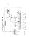
- FIG. 6 shows the structure of a recording / reproducing apparatus 100 in the first example of the present invention.
- the recording / reproducing apparatus 100 records data onto a ferroelectric recording medium 50 and reads the data recorded on the ferroelectric recording medium 50.
- the SNDM reproducing method is adopted to the recording / reproducing apparatus 100.
- the ferroelectric recording medium 50 is provided with: a recording layer 51; and a back electrode (or a back plate) 52.
- the recording layer 51 is constructed from a ferroelectric material.
- the ferroelectric material lithium tantalate (LiTaO 3 ) is used, for example.
- the recording layer 51 is formed in a thin film shape, and a recording surface 51A is formed on one surface thereof.
- the back electrode 52 is an electric conductor and placed on the opposite surface to the recording surface 51A of the recording layer 51.
- the back electrode 52 is earthed.
- the recording / reproducing apparatus 100 is provided with: a spread processor 60; an alternating electric field generator 71; switches 72A to 72N; first inductors 73A to 73N; probes 74A to 74N; a return electrode 75; a second inductor 76; an oscillator 77; a Frequency Modulation (FM) demodulator 78; a de-spreading processor 80; Phase Shift Keying (PSK) demodulators 91A to 91N; and a reproduction circuit 92.
- a spread processor 60 an alternating electric field generator 71; switches 72A to 72N; first inductors 73A to 73N; probes 74A to 74N; a return electrode 75; a second inductor 76; an oscillator 77; a Frequency Modulation (FM) demodulator 78; a de-spreading processor 80; Phase Shift Keying (PSK) demodulators 91A to 91N; and a reproduction circuit 92
- the spread processor 60 is provided with: a divider 61; a spreading code generator 62; and multipliers 63A to 63N.
- the divider 61 receives the record data, divides the record data into bits, and distributes and supplies each of the divided bits (hereinafter referred to as “record bits”) to respective one of the multipliers 63A to 63N. Namely, it is such that the first record bit is supplied to the multiplier 63A, that the second record bit is supplied to the multiplier 63B, and the like.
- the spreading code generator 62 generates the spreading codes.
- the spreading codes are the PN codes. More specifically, general PN code series, such as M series and Gold series, are used as the spreading codes.
- the bit number m of the spreading codes is determined in consideration of the number n of the probes 74A to 74N. Namely, the bit number m of the spreading codes is determined to satisfy 2 m ⁇ n. This causes the spreading code generator 62 to generate the spreading codes of at least n units which are mutually different.
- the spreading codes are used for the DS-SS of the record data by the multiplication by the respective bits of the record data. Therefore, the bit rate of the PN code series for the generation of the spreading codes is faster than that of the record data.
- the spreading code generator 62 is provided with: a shift resister for generating such spreading codes; an adder; or the like.
- Each of the spreading codes of n units generated by the spreading code generator 62 is supplied to respective one of the multipliers 63A to 63N. Namely, it is such that the first spreading code is supplied to the multiplier 63A, that the second spreading code is supplied to the multiplier 63B, and the like.
- Each of the multipliers 63A to 63N multiplies the spreading code and the record bit, thereby to generate the spread bit row.
- the number of the multipliers 63A to 63N is the same as the number of the probes 74A to 74N.
- Each of the spread bit rows generated by the multipliers 63A to 63N is supplied to respective one of the first input terminals of the switches 74A to 74N.
- the alternating electric field generator 71 generates an alternating current signal.
- the frequency of the alternating current signal is about 5 kHz, for example.
- the intensity of the alternating current signal is set not to reach that of the coercive electric field of the ferroelectric substance constituting the recording layer 51 of the ferroelectric recording medium 50.
- the alternating current signal generated by the alternating electric field generator 71 is supplied to each of the second input terminals of the switches 72A to 72N. This alternating current signal is used to generate an alternating electric field onto the ferroelectric substance of the recording layer 51 upon reproducing the record data recorded on the ferroelectric recording medium 50.
- Each of the switches 72A to 72N switches whether to supply the spread bit row inputted to the first input terminal thereof to the side of the probes 74A to 74N or to supply the alternating current signal inputted to the second input terminal thereof to the side of the probes 74A to 74N.
- each of the switches 72A to 72N Upon recording the record data onto the ferroelectric recording medium 50, each of the switches 72A to 72N is switched so that the spread bit row inputted to the first input terminal thereof is supplied to respective one of the probes 74A to 74N.
- each of the switches 72A to 72N is switched so that the alternating current signal inputted to the second input terminal thereof is supplied to respective one of the probes 74A to 74N.
- the switching of the switches 72A to 72N is controlled by a control circuit placed inside the recording / reproducing apparatus 100 (not-illustrated).
- Each of the spread bit rows or the alternating current signal is supplied through the switches 72A to 72N and the first inductors 73A to 73N to the probes 74A to 74N, respectively.
- Each of the probes 74A to 74N is the needle-shaped member having the tip with a diameter of several nanometers, and it is constructed from a carbon nanotube, for example.
- the number of the probes 74A to 74N is several tens to several hundreds.
- the fundamental end (or anchor) side of the probes 74A to 74N is fixed to a head substrate.
- the probes 74A to 74N are placed at predetermined intervals in a matrix shape on the head substrate. Incidentally, the drawing of the accurate arrangement of the probes 74A to 74N is omitted in FIG. 6.
- the head substrate is placed above the recording surface 51A of the ferroelectric recording medium 50 with a space.
- the probes 74A to 74N are placed to project from the head substrate to the recording surface 51A. Upon recording or reading the record data, the tips of the probes 74A to 74N are approached to the recording surface 51A.
- An interval between each of the probes 74A to 74N and the recording surface 51A is several nanometers, for example.
- the head substrate or the ferroelectric recording medium 50 can be moved in the parallel and vertical directions to the recording surface 51A, and this movement is controlled by the control circuit placed inside the recording / reproducing apparatus 100 (not-illustrated).
- the head substrate or the ferroelectric recording medium 50 Upon recording the record data onto the ferroelectric recording medium 50, the head substrate or the ferroelectric recording medium 50 is moved in the vertical direction to the recording surface 51A by the control by the control circuit inside the recording / reproducing apparatus 100, and the tips of the probes 74A to 74N are approached to the recording surface 51A.
- each of the spread bit rows is supplied to respective one of the probes 74A to 74N.
- the spread bit row is supplied as a signal having intensity stronger than the coercive electric field of the ferroelectric substance of the recording layer 51.
- the head substrate or the ferroelectric recording medium 50 is moved in the parallel direction to the recording surface 51A at a predetermined speed by the control by the control circuit inside the recording / reproducing apparatus 100.
- the return electrode 75 is placed above the recording surface 51A with a space and placed to surround the probes 74A to 74N.
- the return electrode 75 is earthed.
- a high frequency electric field applied by the oscillator 77 or the like to the ferroelectric recording medium 50 returns to the earth side through the return electrode 75 (refer to FIG. 4).
- the second inductor 76 forms a resonance circuit with each of the capacitances Csa to Csn just under the probes 74A to 74N.
- the resonance frequency is determined from an inductance L of the second inductor 76 and each of the capacitances Csa to Csn.
- the oscillator 77 generates a high frequency signal which oscillates at the resonance frequency determined from the inductance L and each of the capacitances Csa to Csn.
- the average frequency of the high frequency signal is about 1 GHz.
- the head substrate or the ferroelectric recording medium 50 Upon reproducing the record data recorded on the ferroelectric recording medium 50, the head substrate or the ferroelectric recording medium 50 is moved in the vertical direction to the recording surface 51A by the control by the control circuit inside the recording / reproducing apparatus 100, and the tips of the probes 74A to 74N are approached to the recording surface 51A.
- the alternating current signal generated by the alternating electric field generator 71 is supplied to each of the probes 74A to 74N. This generates the alternating electric field onto the ferroelectric substance of the recording layer 51, and each of the capacitances Csa to Csn changes on the basis of the alternating electric field.
- each of the capacitances Csa to Csn changes (i.e., the change of each differential capacitance) varies depending on the non-linear dielectric constant of the ferroelectric substance of the recording layer 51 located just under respective one of the probes 74A to 74N.
- the non-linear dielectric constant of the ferroelectric substance varies depending on the polarization direction of the ferroelectric substance located just under each of the probes 74A to 74N.
- the bit state of the spread bit row recorded as the polarization direction of the ferroelectric substance just under each of the probes 74A to 74N appears as the difference in how respective one of the capacitances Csa to Csn changes (i.e., the change of each differential capacitance).
- the difference in the change of each differential capacitance is converted into the change in the frequency of the high frequency signal as it is. This means that the high frequency signal generated by the oscillator 77 is frequency-modulated according to each of the spread bit rows recorded on the ferroelectric recording medium 50.
- the head substrate or the ferroelectric recording medium 50 is moved in the parallel direction to the recording surface 51A at a predetermined speed by the control by the control circuit inside the recording / reproducing apparatus 100. This causes the sequential change in the frequency of the high frequency signal according to each of the spread bit rows recorded on the ferroelectric recording medium 50. This is how to read each of the spread bit rows recorded on the ferroelectric recording medium 50.
- the FM demodulator 78 frequency-voltage converts the high frequency signal outputted from the oscillator 77. This causes the change in the frequency of the high frequency signal to be converted into the change in voltage. As a result, a signal whose voltage is changed according to each of the spread bit rows recorded on the ferroelectric recording medium 50 is obtained (hereinafter referred to as a "spread bit row signal").
- the spread bit row signal is supplied to each of the multiplier 82A to 82N of the de-spreading processor 80.
- the de-spreading processor 80 is provided with: a de-spreading code generator 81; and the multiplier 82A to 82N.
- the de-spreading code generator 81 generates the de-spreading codes.
- the de-spreading codes correspond to the spreading codes generated by the spreading code generator 62. Since there are the spreading codes of n units, the de-spreading codes of n units are generated.
- Each of the de-spreading codes is supplied to respective one of the multiplier 82A to 82N. Namely, it is such that the first de-spreading code is supplied to the multiplier 82A, that the second de-spreading code is supplied to the multiplier 82B, and the like.
- Each of the multipliers 82A to 82N multiplies the de-spreading code and the spread bit row signal, thereby to reproduce the record bit of the original record data.
- the number of the multipliers 82A to 82N is the same as the number of the probes 74A to 74N.
- Each of the record bits reproduced by the multipliers 82A to 82N is supplied to respective one of the PSK demodulator 91A to 91N.
- Each of the PSK demodulator 91A to 91N extracts the record bit from a signal outputted from respective one of the multipliers 82A to 82N. Namely, the record bit is reproduced in each of the multipliers 82A to 82N, but the record bit is buried in the signal including various noises.
- Each of the PSK demodulator 91A to 91N extracts the record bit from the signal including various noises.
- Each of the PSK demodulator 91A to 91N is a lock-in amplifier, for example.
- the alternating current signal generated by the alternating electric field generator 71 is used as a reference signal.
- Each of the record bits extracted by the PSK demodulator 91A to 91N is supplied to the reproduction circuit 92.
- the reproduction circuit 92 combines the record bits supplied from the PSK demodulator 91A to 91N, thereby to reproduce the original record data.
- the record data is divided into the bits, and each of the bits is multiplied by respective one of the spreading codes of n units which are mutually different. This generates the spread bit row corresponding to each of the bits of the record data.
- Each of the spread bit rows is distributed and supplied to respective one of the probes 74A to 74N and recorded onto the ferroelectric recording medium 50 through respective one of the probes 74A to 74N. Since the probes 74A to 74N are placed on the head substrate in a matrix shape, the spread bit rows are recorded with them dispersed on the recording surface 51A of the ferroelectric recording medium 50.
- each of the spread bit rows recorded on the ferroelectric recording medium 50 is read as the change in respective one of the capacitances Csa to Csn just under the probes 74A to 74N (which is accurately the change in each differential capacitance). It is converted into the change in the frequency of the high frequency signal and further converted into the change in voltage of the spread bit row signal.
- the spread bit row signal is multiplied by each of the de-spreading codes of n units, thereby to generate the record bit.
- the record bits are combined, thereby to reproduce the original record data.
- the record data is recorded onto the ferroelectric recording medium 50 by the DS-SS of the record data.
- the record data (the spread bit rows) recorded on ferroelectric recording medium 50 is read, de-spread, and reproduced.
- the various noises being such as a defect on the recording surface 51A of the ferroelectric recording medium 50, a noise generated upon reading the record data, and a noise generated upon reproducing the read record data.
- it is possible to highly accurately extract only the record data to be reproduced. This allows the improvement in the noise resistance of the data and the increase in the reliability of the data reproduction.
- each of the bits of the record data is multiplied by respective one of the spreading codes which are mutually different, thereby to generate the spread bit row.
- the spread bit rows are dispersed through respective probes 74A to 74N, thereby to record them.
- each of the spread bit rows read through the probes 74A to 74N is multiplied by respective one of the de-spreading codes which are mutually different, thereby to reproduce each bit of the original record data. In this manner, it is possible to highly accurately and individually separate and extract the record bits of the record data on the basis of the spread bit rows simultaneously and individually read through the probes 74A to 74N.
- a signal read through one probe includes a signal component read through another probe placed around the one probe as a noise.
- the noise of interest can be spread in a broad range by the de-spreading processing, and thus it is possible to certainly extract only information to be read by the one probe. Therefore, it is possible to realize the high speed reading of the data by many probes and the improvement in the reliability and certainty of the data reproduction at the same time.
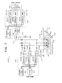
- FIG. 7 shows the structure of a recording / reproducing apparatus 200 in the second example of the present invention.
- the recording / reproducing apparatus 200 is provided with band pass filters (BPFs) 201A to 201N in place of the PSK demodulators 91A to 91N of the recording / reproducing apparatus 100.
- BPFs band pass filters
- Each of the BPFs 201A to 201N extracts the record bit from a signal outputted from respective one of the multipliers 82A to 82N.
- FIG. 8 shows the structure of a recording / reproducing apparatus 300 in the third example of the present invention.
- the recording / reproducing apparatus 300 is provided with a direct current bias voltage generator 301 in place of the alternating electric field generator 71 of the recording / reproducing apparatus 200.
- the direct current bias voltage generator 301 supplies a direct current bias voltage to each of the probes 74A to 74N or the like in order to apply an electric field to the ferroelectric recording medium 50 upon reproducing the spread bit rows recorded on the ferroelectric recording medium 50.
- the electric field generated on the ferroelectric substance of the recording layer 51 by the direct current bias voltage supplied by the direct current bias voltage generator 301 is smaller than the coercive electric field of the ferroelectric substance.
- the alternating current signal is used for the data reproduction in the recording / reproducing apparatuses 100 and 200, while the direct current bias voltage is used for the data reproduction in the recording / reproducing apparatus 300. Therefore, the processing speed of the data reproduction is restricted by the frequency of the alternating electric field in the recording / reproducing apparatuses 100 and 200, while there is not such a restriction in the recording / reproducing apparatus 300. In this regard, the recording / reproducing apparatus 300 can relatively easily increase the processing speed of the data reproduction.
Landscapes
- Engineering & Computer Science (AREA)
- Chemical & Material Sciences (AREA)
- Nanotechnology (AREA)
- Signal Processing (AREA)
- Physics & Mathematics (AREA)
- Mathematical Physics (AREA)
- Theoretical Computer Science (AREA)
- Crystallography & Structural Chemistry (AREA)
- Signal Processing For Digital Recording And Reproducing (AREA)
- Recording Or Reproducing By Magnetic Means (AREA)
- Optical Recording Or Reproduction (AREA)
Abstract
Description
Claims (43)
- A recording / reproducing apparatus (10) for recording data onto a recording medium (1) and reading the data recorded on the recording medium (1), characterized in that said recording / reproducing apparatus comprises:a needle-shaped member (11);a spreading device (12) for generating spread data by performing direct sequence spectrum spreading processing with respect to the data by using a spreading code;a recording device (13) for recording the spread data onto the recording medium through said needle-shaped member;a reading device (14) for reading the spread data recorded by said recording device from the recording medium through said needle-shaped member; anda de-spreading device (15) for performing de-spreading processing with respect to the spread data read from the recording medium by using the spreading code or a de-spreading code corresponding to the spreading code.
- The recording / reproducing apparatus (10) according to claim 1, characterized in that the recording medium (1) is provided with a recording layer (1A) constructed from a ferroelectric substance.
- The recording / reproducing apparatus (10) according to claim 2, characterized in that said reading device comprises:an alternating electric field applying device (16) for applying an alternating electric field to the recording medium;a return electrode (17);an oscillating device (18) for generating a frequency modulation signal whose frequency is changed according to capacitance which is included in capacitance between said needle-shaped member and said return electrode and which corresponds to a non-linear dielectric constant of the ferroelectric substance located just under a tip of said needle-shaped member; anda converting device (19) for frequency-voltage converting the frequency modulation signal generated by said oscillating device.
- The recording / reproducing apparatus (10) according to claim 3, characterized in that said return electrode (17) and said needle-shaped member (11) are disposed on a same side with respect to the recording medium (1).
- The recording / reproducing apparatus (10) according to claim 3 or 4, characterized in that said recording / reproducing apparatus comprises a bias voltage applying device (301) for applying a direct current bias voltage to the recording medium in place of said alternating electric field applying device (16).
- The recording / reproducing apparatus (10) according to any one of claims 2 to 5, characterized in that said recording / reproducing apparatus further comprises a signal processing device (91, 201) for extracting the data from a signal obtained by that said de-spreading device (15) performs de-spreading processing with respect to the spread data read from the recording medium.
- The recording / reproducing apparatus (10) according to claim 6, characterized in that said signal processing device (91, 201) includes a Phase Shift Keying (PSK) demodulator.
- The recording / reproducing apparatus (10) according to claim 6, characterized in that said signal processing device (91, 201) includes a filter which allows only a predetermined frequency band to be passed.
- The recording / reproducing apparatus (10) according to any one of claims 1 to 8, characterized in that the spreading code is a Pseudorandom Noise (PN) code.
- A recording / reproducing apparatus (20) for recording data onto a recording medium (1) and reading the data recorded on the recording medium (1), characterized in that said recording / reproducing apparatus comprises:a plurality of needle-shaped members (21A-21N);a spreading device (22) for generating spread data by performing direct sequence spectrum spreading processing with respect to the data by individually multiplying respective bits of the data by a plurality of spreading codes which are mutually different;a recording device (23) for recording the spread data onto the recording medium through said plurality of needle-shaped members;a reading device (24) for reading the spread data recorded by said recording device from the recording medium through said plurality of needle-shaped members; anda de-spreading device (25) for performing de-spreading processing with respect to the spread data read from the recording medium by using the plurality of spreading codes or a plurality of de-spreading codes respectively corresponding to the plurality of spreading codes.
- The recording / reproducing apparatus (20) according to claim 10, characterized in that
said spreading device (22) generates a plurality of spread bit rows each of which corresponds to the respective bits of the data by individually multiplying the bits of the data by the plurality of spreading codes respectively corresponding to the bits, and
said recording device (23) distributes and supplies the plurality of spread bit rows to said plurality of needle-shaped members (21A-21N) for each spread bit row and records each spread bit row onto the recording medium. - The recording / reproducing apparatus (20) according to claim 10 or 11, characterized in that the recording medium (1) is provided with a recording layer (1A) constructed from a ferroelectric substance.
- The recording / reproducing apparatus (20) according to claim 12, characterized in that said reading device (23) comprises:an alternating electric field applying device (16) for applying an alternating electric field to the recording medium;a return electrode (17);an oscillating device (18) for generating a frequency modulation signal whose frequency is changed according to capacitance which is included in capacitance between each of said plurality of needle-shaped members and said return electrode and which corresponds to a non-linear dielectric constant of the ferroelectric substance located just under a tip of each of said plurality of needle-shaped members; anda converting device (19) for frequency-voltage converting the frequency modulation signal generated by said oscillating device.
- The recording / reproducing apparatus (20) according to claim 13, characterized in that said return electrode (17) is disposed on the one surface side of the recording medium (1) as well as said plurality of needle-shaped members (21A-21N).
- The recording / reproducing apparatus (20) according to claim 13 or 14, characterized in that said recording / reproducing apparatus comprises a bias voltage applying device (301) for applying a direct current bias voltage to the recording medium in place of said alternating electric field applying device (16).
- The recording / reproducing apparatus (20) according to any one of claims 12 to 15, characterized in that said recording / reproducing apparatus further comprises a signal processing device (91, 201) for extracting the data from a signal obtained by that said de-spreading device (25) performs de-spreading processing with respect to the spread data read from the recording medium.
- The recording / reproducing apparatus (20) according to claim 16, characterized in that said signal processing device (91, 201) includes a Phase Shift Keying (PSK) demodulator.
- The recording / reproducing apparatus (20) according to claim 16, characterized in that said signal processing device (91, 201) includes a filter which allows only a predetermined frequency band to be passed.
- The recording / reproducing apparatus (20) according to any one of claims 10 to 18, characterized in that each of the plurality of spreading codes is a Pseudorandom Noise (PN) code.
- A recording apparatus (10) for recording data onto a recording medium (1), characterized in that said recording apparatus comprises:a needle-shaped member (11);a spreading device (12) for generating spread data by performing direct sequence spectrum spreading processing with respect to the data by using a spreading code; anda recording device (13) for recording the spread data onto the recording medium through said needle-shaped member.
- The recording apparatus (10) according to claim 20, characterized in that the spreading code is a Pseudorandom Noise (PN) code.
- A recording apparatus (20) for recording data onto a recording medium (1), characterized in that said recording apparatus comprises:a plurality of needle-shaped members (21A-21N);a spreading device (22) for generating spread data by performing direct sequence spectrum spreading processing with respect to the data by individually multiplying respective bits of the data by a plurality of spreading codes which are mutually different; anda recording device (23) for recording the spread data onto the recording medium through said plurality of needle-shaped members.
- The recording apparatus (20) according to claim 22, characterized in that
said spreading device (22) generates a plurality of spread bit rows each of which corresponds to the respective bits of the data by individually multiplying the bits of the data by the plurality of spreading codes respectively corresponding to the bits, and
said recording device (23) distributes and supplies the plurality of spread bit rows to said plurality of needle-shaped members for each spread bit row and records each spread bit row onto the recording medium. - The recording / reproducing apparatus (20) according to claim 22 or 23, characterized in that each of the plurality of spreading codes is a Pseudorandom Noise (PN) code.
- A reproducing apparatus (10) for reproducing data from a recording medium (1) onto which spread data generated by performing direct sequence spectrum spreading processing with respect to the data by using a spreading code is recorded, characterized in that said reproducing apparatus comprises:a needle-shaped member (11);a reading device (14) for reading the spread data from the recording medium through said needle-shaped member; anda de-spreading device (15) for performing de-spreading processing with respect to the spread data read from the recording medium by using the spreading code or a de-spreading code corresponding to the spreading code.
- The reproducing apparatus (10) according to claim 25, characterized in that the recording medium (1) is provided with a recording layer (1A) constructed from a ferroelectric substance.
- The reproducing apparatus (10) according to claim 26, characterized in that said reading device (14) comprises:an alternating electric field applying device (16) for applying an alternating electric field to the recording medium;a return electrode (17);an oscillating device (18) for generating a frequency modulation signal whose frequency is changed according to capacitance which is included in capacitance between said needle-shaped member and said return electrode and which corresponds to a non-linear dielectric constant of the ferroelectric substance located just under a tip of said needle-shaped member; anda converting device (19) for frequency-voltage converting the frequency modulation signal generated by said oscillating device.
- The reproducing apparatus (10) according to claim 27, characterized in that said return electrode (17) and said needle-shaped member (11) are disposed on a same side with respect to the recording medium (1).
- The reproducing apparatus (10) according to claim 27 or 28, characterized in that said reproducing apparatus comprises a bias voltage applying device (301) for applying a direct current bias voltage to the recording medium in place of said alternating electric field applying device (16).
- The reproducing apparatus (10) according to any one of claims 26 to 29, characterized in that said reproducing apparatus further comprises a signal processing device (91, 201) for extracting the data from a signal obtained by that said de-spreading device (15) performs de-spreading processing with respect to the spread data read from the recording medium.
- The reproducing apparatus (10) according to claim 30, characterized in that said signal processing device (91, 201) includes a Phase Shift Keying (PSK) demodulator.
- The reproducing apparatus (10) according to claim 30, characterized in that said signal processing device (91, 201) includes a filter which allows only a predetermined frequency band to be passed.
- The reproducing apparatus (10) according to any one of claims 25 to 32, characterized in that the spreading code is a Pseudorandom Noise (PN) code.
- A reproducing apparatus (20) for reproducing data from a recording medium (1) onto which spread data generated by performing direct sequence spectrum spreading processing with respect to the data by individually multiplying respective bits of the data by a plurality of spreading codes which are mutually different is recorded, characterized in that said reproducing apparatus comprises:a plurality of needle-shaped members (21A-21N);a reading device (24) for reading the spread data recorded by said recording device from the recording medium through said plurality of needle-shaped members; anda de-spreading device (25) for performing de-spreading processing with respect to the spread data read from the recording medium by using the plurality of spreading codes or a plurality of de-spreading codes respectively corresponding to the plurality of spreading codes.
- The reproducing apparatus (20) according to claim 34, characterized in that the recording medium (1) is provided with a recording layer (1A) constructed from a ferroelectric substance.
- The reproducing apparatus (20) according to claim 35, characterized in that said reading device (24) comprises:an alternating electric field applying device (16) for applying an alternating electric field to the recording medium;a return electrode (17);an oscillating device (18) for generating a frequency modulation signal whose frequency is changed according to capacitance which is included in capacitance between each of said plurality of needle-shaped members and said return electrode and which corresponds to a non-linear dielectric constant of the ferroelectric substance located just under a tip of each of said plurality of needle-shaped members; anda converting device (19) for frequency-voltage converting the frequency modulation signal generated by said oscillating device.
- The reproducing apparatus (20) according to claim 36, characterized in that said return electrode (17) and said plurality of needle-shaped members (21A-21N) are disposed on a same side with respect to the recording medium (1).
- The reproducing apparatus (20) according to claim 36 or 37, characterized in that said reproducing apparatus comprises a bias voltage applying device for (301) applying a direct current bias voltage to the recording medium in place of said alternating electric field applying device (16).
- The reproducing apparatus (20) according to any one of claims 35 to 38, characterized in that said reproducing apparatus further comprises a signal processing device (91, 201) for extracting the data from a signal obtained by that said de-spreading device (25) performs de-spreading processing with respect to the spread data read from the recording medium.
- The reproducing apparatus (20) according to claim 39, characterized in that said signal processing device (91, 201) includes a Phase Shift Keying (PSK) demodulator.
- The reproducing apparatus (20) according to claim 39, characterized in that said signal processing device (91, 201) includes a filter which allows only a predetermined frequency band to be passed.
- The reproducing apparatus (20) according to any one of claims 34 to 41, characterized in that each of the plurality of spreading codes is a Pseudorandom Noise (PN) code.
- A recording / reproducing method of recording data onto a recording medium (1) through a needle-shaped member (11), and reading and reproducing the data recorded on the recording medium (1) through the needle-shaped member (11), characterized in that said recording / reproducing method comprises:a spreading process of generating spread data by performing direct sequence spectrum spreading processing with respect to the data by using a spreading code;a recording process of recording the spread data onto the recording medium through said needle-shaped member;a reading process of reading the spread data recorded in said recording process from the recording medium through said needle-shaped member; anda de-spreading process of performing de-spreading processing with respect to the spread data read from the recording medium by using the spreading code or a de-spreading code corresponding to the spreading code.
Applications Claiming Priority (2)
| Application Number | Priority Date | Filing Date | Title |
|---|---|---|---|
| JP2003167604A JP2005004890A (en) | 2003-06-12 | 2003-06-12 | Data recording/reproducing device using needle-like member, and data recording/reproducing method |
| JP2003167604 | 2003-06-12 |
Publications (4)
| Publication Number | Publication Date |
|---|---|
| EP1486966A2 true EP1486966A2 (en) | 2004-12-15 |
| EP1486966A3 EP1486966A3 (en) | 2006-04-12 |
| EP1486966B1 EP1486966B1 (en) | 2007-09-12 |
| EP1486966B8 EP1486966B8 (en) | 2007-11-07 |
Family
ID=33296869
Family Applications (1)
| Application Number | Title | Priority Date | Filing Date |
|---|---|---|---|
| EP20040013728 Expired - Lifetime EP1486966B8 (en) | 2003-06-12 | 2004-06-11 | Data recording / reproducing apparatus and method using needle-shaped member |
Country Status (4)
| Country | Link |
|---|---|
| US (2) | US7385901B2 (en) |
| EP (1) | EP1486966B8 (en) |
| JP (1) | JP2005004890A (en) |
| DE (1) | DE602004008832T2 (en) |
Cited By (1)
| Publication number | Priority date | Publication date | Assignee | Title |
|---|---|---|---|---|
| GB2407694A (en) * | 2003-10-31 | 2005-05-04 | Hewlett Packard Development Co | Ferroelectric data storage device |
Families Citing this family (20)
| Publication number | Priority date | Publication date | Assignee | Title |
|---|---|---|---|---|
| US7260051B1 (en) | 1998-12-18 | 2007-08-21 | Nanochip, Inc. | Molecular memory medium and molecular memory integrated circuit |
| DE60234367D1 (en) * | 2001-09-10 | 2009-12-24 | Pioneer Corp | DIELECTRICITY CONSTANT MEASUREMENT DEVICE AND DIELECTRICITY CONSTANT MEASUREMENT METHOD |
| JP4771324B2 (en) * | 2001-09-10 | 2011-09-14 | パイオニア株式会社 | Dielectric information apparatus, tape-shaped medium recording / reproducing apparatus, and disk-shaped medium recording / reproducing apparatus |
| JP4141745B2 (en) * | 2002-06-06 | 2008-08-27 | 康雄 長 | Dielectric recording / reproducing head, dielectric recording medium unit, and dielectric recording / reproducing apparatus |
| JP4082947B2 (en) * | 2002-07-09 | 2008-04-30 | パイオニア株式会社 | Recording / reproducing head and manufacturing method thereof |
| JP4017104B2 (en) * | 2002-07-09 | 2007-12-05 | パイオニア株式会社 | Dielectric recording / reproducing head and tracking method |
| JP3954456B2 (en) * | 2002-07-09 | 2007-08-08 | パイオニア株式会社 | Pickup device |
| JP3701268B2 (en) | 2002-09-11 | 2005-09-28 | 康雄 長 | Dielectric recording apparatus, dielectric reproducing apparatus, and dielectric recording / reproducing apparatus |
| JP4098689B2 (en) | 2002-09-11 | 2008-06-11 | 康雄 長 | Dielectric reproducing apparatus, dielectric recording apparatus, and dielectric recording / reproducing apparatus |
| JP4274571B2 (en) * | 2003-05-01 | 2009-06-10 | 康雄 長 | Recording / reproducing head and recording / reproducing apparatus |
| JP2005004890A (en) * | 2003-06-12 | 2005-01-06 | Yasuo Cho | Data recording/reproducing device using needle-like member, and data recording/reproducing method |
| WO2005019118A1 (en) * | 2003-08-22 | 2005-03-03 | Fmc Foret, S.A. | Method, devices and reagents which are used for wastewater treatment |
| WO2005020227A1 (en) | 2003-08-25 | 2005-03-03 | Pioneer Corporation | Signal detection method and device, and information reproduction device and method |
| FR2876831B1 (en) * | 2004-10-15 | 2007-02-02 | Commissariat Energie Atomique | DATA RECORDING DEVICE HAVING INCLINED CARBON NANOTUBES AND METHOD FOR MANUFACTURING THE SAME |
| US7463573B2 (en) | 2005-06-24 | 2008-12-09 | Nanochip, Inc. | Patterned media for a high density data storage device |
| US7626846B2 (en) | 2007-07-16 | 2009-12-01 | Nanochip, Inc. | Method and media for improving ferroelectric domain stability in an information storage device |
| KR20100000321A (en) * | 2008-06-24 | 2010-01-06 | 삼성전자주식회사 | Apparatus and method for reading signal in ferroelectric hard disk drive |
| US20110242310A1 (en) * | 2010-01-07 | 2011-10-06 | University Of Delaware | Apparatus and Method for Electrospinning Nanofibers |
| JP5761251B2 (en) * | 2013-05-22 | 2015-08-12 | 株式会社村田製作所 | Antenna device and communication device |
| KR102594656B1 (en) * | 2016-11-25 | 2023-10-26 | 삼성전자주식회사 | Security Processor, Application Processor having the same and Operating Method of Security Processor |
Family Cites Families (78)
| Publication number | Priority date | Publication date | Assignee | Title |
|---|---|---|---|---|
| GB644426A (en) | 1947-08-21 | 1950-10-11 | Ian Irvine Boswell | Improvements in or relating to sound recording and reproducing systems |
| US2872529A (en) | 1953-03-10 | 1959-02-03 | Hans E Hollmann | Apparatus for recording signals |
| GB1484256A (en) | 1974-11-14 | 1977-09-01 | Emi Ltd | Arrangements for sensing recorded information signals |
| JPS55139643A (en) | 1979-04-13 | 1980-10-31 | Toshiba Corp | Semiconductor recording and reproduction system |
| JPS56107338A (en) | 1980-01-29 | 1981-08-26 | Hitachi Ltd | Detector for tracking error |
| US4320491A (en) | 1980-09-19 | 1982-03-16 | Rca Corporation | Apparatus for video disc stylus electrode reconditioning |
| JPS57200956A (en) | 1981-06-04 | 1982-12-09 | Keiji Suzuki | Electrostatic capacity type information reproducing device |
| US4455638A (en) | 1982-04-02 | 1984-06-19 | Rca Corporation | RF Radial choke for use in record playback apparatus |
| US4489278A (en) | 1982-06-03 | 1984-12-18 | Tokyo Shibaura Denki Kabushiki Kaisha | Electrostatic voltage detecting device |
| JPS5922250A (en) | 1982-07-26 | 1984-02-04 | Sanyo Electric Co Ltd | Scanning stylus of pickup |
| DE69031053T2 (en) | 1989-04-25 | 1998-01-29 | Canon Kk | Information recording / reproducing apparatus and information recording medium |
| EP0398656B1 (en) | 1989-05-16 | 1995-11-08 | Victor Company Of Japan, Ltd. | Electric charge image recording medium and recording/reproducing apparatus |
| JP2628790B2 (en) | 1989-06-23 | 1997-07-09 | ザ ボード オブ トラスティーズ オブ ザ リーランド スタンフォード ジュニア ユニバーシティ | Method and apparatus for storing digital information in the form of stored charges |
| JPH041948A (en) | 1990-04-18 | 1992-01-07 | Canon Inc | Information recorder, information reproducer and their applied information recording and reproducing device |
| US5047649A (en) | 1990-10-09 | 1991-09-10 | International Business Machines Corporation | Method and apparatus for writing or etching narrow linewidth patterns on insulating materials |
| JPH04301219A (en) | 1991-03-28 | 1992-10-23 | Pioneer Electron Corp | Constant angular velocity type optical disk and double density recording method for constant angular velocity type optical disk |
| US5418029A (en) | 1992-01-28 | 1995-05-23 | Fuji Photo Film Co., Ltd. | Information recording medium and method |
| JPH05282717A (en) | 1992-03-31 | 1993-10-29 | Canon Inc | Recording medium manufacturing method, recording medium, and information processing apparatus |
| JP3029499B2 (en) | 1992-05-07 | 2000-04-04 | キヤノン株式会社 | Recording and playback device |
| JP3744944B2 (en) | 1992-07-17 | 2006-02-15 | パイオニア株式会社 | Optical disc, tracking error signal generation device, and tracking control device |
| US5635037A (en) | 1993-08-02 | 1997-06-03 | Industrial Technology Research Institute | Method of texture by in-situ masking and etching for thin film magnetic recording medium |
| JPH07334940A (en) * | 1994-06-02 | 1995-12-22 | Matsushita Electric Ind Co Ltd | Digital signal recording / reproducing device |
| JP3204852B2 (en) | 1994-09-02 | 2001-09-04 | 株式会社村田製作所 | Non-linear dielectric constant measuring device |
| JPH08297871A (en) | 1995-04-21 | 1996-11-12 | Hewlett Packard Co <Hp> | High-density recording medium and large-capacity recorder |
| US5724336A (en) | 1995-04-25 | 1998-03-03 | Morton; Steven G. | Tera-byte disk drive |
| JPH08329538A (en) | 1995-05-30 | 1996-12-13 | Hewlett Packard Co <Hp> | Probe device |
| JP3716467B2 (en) | 1995-07-19 | 2005-11-16 | ソニー株式会社 | Recording medium, information reproducing apparatus, information recording apparatus, and information recording / reproducing apparatus |
| EP0783748B1 (en) | 1995-07-28 | 2001-11-21 | International Business Machines Corporation | Mass-storage applications of local probe arrays |
| JPH09120593A (en) | 1995-08-23 | 1997-05-06 | Sony Corp | Recording and playback device |
| KR970017286A (en) | 1995-09-06 | 1997-04-30 | 가나이 츠토무 | Tracking method and storage |
| JPH09222430A (en) | 1996-02-16 | 1997-08-26 | Canon Inc | Probe unit and information recording / reproducing apparatus using the same |
| DE69712768T2 (en) | 1996-07-18 | 2003-01-23 | Asahi Glass Co., Ltd. | FLUORINATED ORGANOSILICONE COMPOUNDS AND METHOD FOR THE PRODUCTION THEREOF |
| US5985404A (en) | 1996-08-28 | 1999-11-16 | Tdk Corporation | Recording medium, method of making, and information processing apparatus |
| JPH10334525A (en) | 1996-12-19 | 1998-12-18 | Sony Corp | Recording and / or reproducing method, recording and / or reproducing apparatus |
| US6001519A (en) | 1997-01-22 | 1999-12-14 | Industrial Technology Research Institute | High molecular weight information recording medium and related data writing method |
| JP3472087B2 (en) | 1997-06-30 | 2003-12-02 | Tdk株式会社 | Film structure, electronic device, recording medium, and method for producing oxide conductive thin film |
| JP4160135B2 (en) | 1997-07-31 | 2008-10-01 | 三星電子株式会社 | Disk device using ferroelectric thin film |
| JP3978818B2 (en) | 1997-08-08 | 2007-09-19 | ソニー株式会社 | Manufacturing method of micro head element |
| JPH11176033A (en) | 1997-12-09 | 1999-07-02 | Fujitsu Ltd | Recording / playback head device |
| US6477132B1 (en) | 1998-08-19 | 2002-11-05 | Canon Kabushiki Kaisha | Probe and information recording/reproduction apparatus using the same |
| US7260051B1 (en) | 1998-12-18 | 2007-08-21 | Nanochip, Inc. | Molecular memory medium and molecular memory integrated circuit |
| JP3844414B2 (en) | 1999-08-31 | 2006-11-15 | パイオニア株式会社 | Surface acoustic wave device and manufacturing method thereof |
| JP3688530B2 (en) | 1999-09-29 | 2005-08-31 | 株式会社東芝 | Recording medium, recording apparatus, and recording method |
| US6515957B1 (en) | 1999-10-06 | 2003-02-04 | International Business Machines Corporation | Ferroelectric drive for data storage |
| JP2001223701A (en) * | 2000-02-09 | 2001-08-17 | Hitachi Telecom Technol Ltd | ATM equipment |
| KR100331451B1 (en) | 2000-05-10 | 2002-04-09 | 윤종용 | Rewritable data storage using carbonaceous material and writing and reading method thereof |
| US6606726B1 (en) | 2000-06-13 | 2003-08-12 | Telefonaktiebolaget L M Ericsson (Publ) | Optimization of acceptance of erroneous codewords and throughput |
| TW567479B (en) | 2000-08-18 | 2003-12-21 | Matsushita Electric Industrial Co Ltd | Data recording medium and record generation method thereof |
| JP2002074678A (en) | 2000-09-04 | 2002-03-15 | Pioneer Electronic Corp | Optical recording medium |
| KR100389903B1 (en) | 2000-12-01 | 2003-07-04 | 삼성전자주식회사 | Mass data storage and the method of writing and reading therof by contact resitance measurement |
| JP2002214462A (en) | 2001-01-22 | 2002-07-31 | Pioneer Electronic Corp | Optical integrated circuit and its manufacturing method |
| JPWO2002073612A1 (en) | 2001-03-14 | 2005-01-27 | ソニー株式会社 | Optical recording / reproducing apparatus, optical reproducing apparatus, optical recording / reproducing medium, optical recording / reproducing method, optical recording method, optical reproducing method, and optical layer detecting method |
| JP2002277656A (en) | 2001-03-19 | 2002-09-25 | Pioneer Electronic Corp | Optical integrated circuit and its manufacturing method |
| JP4771324B2 (en) * | 2001-09-10 | 2011-09-14 | パイオニア株式会社 | Dielectric information apparatus, tape-shaped medium recording / reproducing apparatus, and disk-shaped medium recording / reproducing apparatus |
| DE60234367D1 (en) | 2001-09-10 | 2009-12-24 | Pioneer Corp | DIELECTRICITY CONSTANT MEASUREMENT DEVICE AND DIELECTRICITY CONSTANT MEASUREMENT METHOD |
| US6653630B2 (en) | 2001-11-30 | 2003-11-25 | Ramot - University Authority For Applied Research & Industrial Development Ltd. | Tailoring domain engineered structures in ferroelectric materials |
| JP2003296979A (en) | 2002-01-31 | 2003-10-17 | Yasuo Cho | System of extracting recording condition of dielectric recording medium, recording condition extracting method and information recorder |
| JP4082911B2 (en) | 2002-01-31 | 2008-04-30 | パイオニア株式会社 | Dielectric recording medium, method for manufacturing the same, and apparatus for manufacturing the same |
| JP2003263804A (en) | 2002-03-08 | 2003-09-19 | Pioneer Electronic Corp | Dielectric recording medium, and method and apparatus for manufacturing the same |
| JP4109475B2 (en) | 2002-03-26 | 2008-07-02 | パイオニア株式会社 | Dielectric recording medium, method for manufacturing the same, and apparatus for manufacturing the same |
| JP3850746B2 (en) * | 2002-03-27 | 2006-11-29 | 株式会社東芝 | Photomask, focus monitor method, exposure amount monitor method, and semiconductor device manufacturing method |
| US7065545B2 (en) * | 2002-05-07 | 2006-06-20 | Quintero-De-La-Garza Raul Gera | Computer methods of vector operation for reducing computation time |
| EP1385161B1 (en) | 2002-05-23 | 2008-09-17 | International Business Machines Corporation | Storage device and method for scanning a storage medium |
| JP4141745B2 (en) | 2002-06-06 | 2008-08-27 | 康雄 長 | Dielectric recording / reproducing head, dielectric recording medium unit, and dielectric recording / reproducing apparatus |
| JP3954456B2 (en) | 2002-07-09 | 2007-08-08 | パイオニア株式会社 | Pickup device |
| JP3954457B2 (en) | 2002-07-09 | 2007-08-08 | パイオニア株式会社 | Dielectric recording medium and dielectric recording / reproducing apparatus |
| JP4017104B2 (en) | 2002-07-09 | 2007-12-05 | パイオニア株式会社 | Dielectric recording / reproducing head and tracking method |
| JP3701268B2 (en) | 2002-09-11 | 2005-09-28 | 康雄 長 | Dielectric recording apparatus, dielectric reproducing apparatus, and dielectric recording / reproducing apparatus |
| JP4141811B2 (en) | 2002-11-18 | 2008-08-27 | パイオニア株式会社 | Information recording / reading head |
| JP3958196B2 (en) | 2002-11-28 | 2007-08-15 | 康雄 長 | Dielectric recording / reproducing head and dielectric recording / reproducing apparatus |
| JP2004192741A (en) | 2002-12-12 | 2004-07-08 | Pioneer Electronic Corp | Information recording/reading head and information recording/reproducing device |
| JP4274571B2 (en) | 2003-05-01 | 2009-06-10 | 康雄 長 | Recording / reproducing head and recording / reproducing apparatus |
| JP2005004890A (en) | 2003-06-12 | 2005-01-06 | Yasuo Cho | Data recording/reproducing device using needle-like member, and data recording/reproducing method |
| JP4328330B2 (en) | 2003-08-20 | 2009-09-09 | パイオニア株式会社 | Data recording / reproducing apparatus, data recording / reproducing method, and recording medium |
| JP4641943B2 (en) | 2003-08-21 | 2011-03-02 | 康雄 長 | Ferroelectric thin film manufacturing method, voltage application etching apparatus, ferroelectric crystal thin film substrate, and ferroelectric crystal wafer |
| JP4249573B2 (en) | 2003-09-03 | 2009-04-02 | パイオニア株式会社 | Recording medium having position recognition structure, position recognition device, and position recognition method |
| JP4145773B2 (en) | 2003-11-06 | 2008-09-03 | パイオニア株式会社 | Information recording / reproducing apparatus and recording medium |
| JP2005158117A (en) | 2003-11-21 | 2005-06-16 | Pioneer Electronic Corp | Recording and reproducing head, manufacturing method of recording and reproducing head, recording apparatus, and reproducing apparatus |
-
2003
- 2003-06-12 JP JP2003167604A patent/JP2005004890A/en active Pending
-
2004
- 2004-06-11 DE DE200460008832 patent/DE602004008832T2/en not_active Expired - Lifetime
- 2004-06-11 EP EP20040013728 patent/EP1486966B8/en not_active Expired - Lifetime
- 2004-06-14 US US10/866,197 patent/US7385901B2/en not_active Expired - Fee Related
-
2008
- 2008-04-04 US US12/078,756 patent/US8004948B2/en not_active Expired - Fee Related
Cited By (4)
| Publication number | Priority date | Publication date | Assignee | Title |
|---|---|---|---|---|
| GB2407694A (en) * | 2003-10-31 | 2005-05-04 | Hewlett Packard Development Co | Ferroelectric data storage device |
| GB2407694B (en) * | 2003-10-31 | 2008-02-27 | Hewlett Packard Development Co | Data storage device |
| US7391706B2 (en) | 2003-10-31 | 2008-06-24 | Samsung Electronics Co., Ltd. | Data storage device including conductive probe and ferroelectric storage medium |
| US7869336B1 (en) | 2003-10-31 | 2011-01-11 | Samsung Electronics Co., Ltd. | Data storage devices including conductive probes and ferroelectric storage medium and methods of operating the same |
Also Published As
| Publication number | Publication date |
|---|---|
| US7385901B2 (en) | 2008-06-10 |
| DE602004008832D1 (en) | 2007-10-25 |
| US20040252621A1 (en) | 2004-12-16 |
| US8004948B2 (en) | 2011-08-23 |
| JP2005004890A (en) | 2005-01-06 |
| EP1486966B1 (en) | 2007-09-12 |
| US20100284263A1 (en) | 2010-11-11 |
| DE602004008832T2 (en) | 2008-06-19 |
| EP1486966B8 (en) | 2007-11-07 |
| EP1486966A3 (en) | 2006-04-12 |
Similar Documents
| Publication | Publication Date | Title |
|---|---|---|
| US8004948B2 (en) | Data recording / reproducing apparatus and method using needle-shaped member | |
| US5276672A (en) | Micro-displacement type information detection probe device and scanning tunneling microscope, atomic force microscope, information processing device by use thereof | |
| EP1394789B1 (en) | Dielectric recording / reproducing head and tracking method | |
| JP3073616B2 (en) | Information processing device with multiple probes | |
| US6665258B1 (en) | Method and apparatus for recording, storing and reproducing information | |
| WO2000036608A2 (en) | Molecular memory medium and molecular memory integrated circuit | |
| US5371728A (en) | Information recording/reproducing apparatus using probe | |
| JP2002025134A (en) | Rewritable data storage using carbon-containing material, and its writing method and reading method | |
| US5432771A (en) | Information recording/reproducing apparatus for performing recording/reproduction of information by using probe | |
| JPH04212739A (en) | Recording and reproducing method and device | |
| CN101025969B (en) | Information media and method and apparatus for writing and reproducing information using the same | |
| CN100411038C (en) | Probe storage device and method for detecting data in probe storage device | |
| JP3135753B2 (en) | Recording / reproducing method and apparatus using probe | |
| JP2968610B2 (en) | Information recording / reproducing device | |
| JP3078141B2 (en) | Recording device and recording / reproducing device | |
| JP3121159B2 (en) | Recording and reproducing method and apparatus | |
| JP3937486B2 (en) | Recording apparatus and recording / reproducing apparatus | |
| JP3118654B2 (en) | Information processing device and scanning tunneling electron microscope | |
| JP2802675B2 (en) | Probe forming method and apparatus | |
| JPH117667A (en) | Recording / reproducing apparatus and recording / reproducing method | |
| JP2968624B2 (en) | Tip scanning method | |
| JPH05334737A (en) | Tracking method and information processor using the same | |
| JPH05342648A (en) | Information reading and/or inputting device | |
| JPH06267120A (en) | Multi-probe head and recording / reproducing apparatus having the same | |
| JP2000315330A (en) | Information recording / reproducing device |
Legal Events
| Date | Code | Title | Description |
|---|---|---|---|
| PUAI | Public reference made under article 153(3) epc to a published international application that has entered the european phase |
Free format text: ORIGINAL CODE: 0009012 |
|
| AK | Designated contracting states |
Kind code of ref document: A2 Designated state(s): AT BE BG CH CY CZ DE DK EE ES FI FR GB GR HU IE IT LI LU MC NL PL PT RO SE SI SK TR |
|
| AX | Request for extension of the european patent |
Extension state: AL HR LT LV MK |
|
| PUAL | Search report despatched |
Free format text: ORIGINAL CODE: 0009013 |
|
| AK | Designated contracting states |
Kind code of ref document: A3 Designated state(s): AT BE BG CH CY CZ DE DK EE ES FI FR GB GR HU IE IT LI LU MC NL PL PT RO SE SI SK TR |
|
| AX | Request for extension of the european patent |
Extension state: AL HR LT LV MK |
|
| RIC1 | Information provided on ipc code assigned before grant |
Ipc: G11B 20/24 20060101ALI20060222BHEP Ipc: G11B 20/18 20060101ALI20060222BHEP Ipc: G11B 20/10 20060101ALI20060222BHEP Ipc: G11B 9/00 20060101AFI20040927BHEP |
|
| 17P | Request for examination filed |
Effective date: 20060531 |
|
| AKX | Designation fees paid |
Designated state(s): DE FR GB |
|
| GRAP | Despatch of communication of intention to grant a patent |
Free format text: ORIGINAL CODE: EPIDOSNIGR1 |
|
| GRAS | Grant fee paid |
Free format text: ORIGINAL CODE: EPIDOSNIGR3 |
|
| GRAA | (expected) grant |
Free format text: ORIGINAL CODE: 0009210 |
|
| AK | Designated contracting states |
Kind code of ref document: B1 Designated state(s): DE FR GB |
|
| REG | Reference to a national code |
Ref country code: GB Ref legal event code: FG4D |
|
| RBV | Designated contracting states (corrected) |
Designated state(s): DE GB |
|
| REF | Corresponds to: |
Ref document number: 602004008832 Country of ref document: DE Date of ref document: 20071025 Kind code of ref document: P |
|
| REG | Reference to a national code |
Ref country code: GB Ref legal event code: 746 Effective date: 20080527 |
|
| PLBE | No opposition filed within time limit |
Free format text: ORIGINAL CODE: 0009261 |
|
| STAA | Information on the status of an ep patent application or granted ep patent |
Free format text: STATUS: NO OPPOSITION FILED WITHIN TIME LIMIT |
|
| 26N | No opposition filed |
Effective date: 20080613 |
|
| PGFP | Annual fee paid to national office [announced via postgrant information from national office to epo] |
Ref country code: GB Payment date: 20110608 Year of fee payment: 8 |
|
| PGFP | Annual fee paid to national office [announced via postgrant information from national office to epo] |
Ref country code: DE Payment date: 20110608 Year of fee payment: 8 |
|
| GBPC | Gb: european patent ceased through non-payment of renewal fee |
Effective date: 20120611 |
|
| REG | Reference to a national code |
Ref country code: DE Ref legal event code: R119 Ref document number: 602004008832 Country of ref document: DE Effective date: 20130101 |
|
| PG25 | Lapsed in a contracting state [announced via postgrant information from national office to epo] |
Ref country code: GB Free format text: LAPSE BECAUSE OF NON-PAYMENT OF DUE FEES Effective date: 20120611 Ref country code: DE Free format text: LAPSE BECAUSE OF NON-PAYMENT OF DUE FEES Effective date: 20130101 |