EP1486946A1 - Image display apparatus, image processing method, program, and recording medium - Google Patents
Image display apparatus, image processing method, program, and recording medium Download PDFInfo
- Publication number
- EP1486946A1 EP1486946A1 EP03708608A EP03708608A EP1486946A1 EP 1486946 A1 EP1486946 A1 EP 1486946A1 EP 03708608 A EP03708608 A EP 03708608A EP 03708608 A EP03708608 A EP 03708608A EP 1486946 A1 EP1486946 A1 EP 1486946A1
- Authority
- EP
- European Patent Office
- Prior art keywords
- color
- color correction
- display device
- image display
- image
- Prior art date
- Legal status (The legal status is an assumption and is not a legal conclusion. Google has not performed a legal analysis and makes no representation as to the accuracy of the status listed.)
- Withdrawn
Links
Images


Classifications
-
- H—ELECTRICITY
- H04—ELECTRIC COMMUNICATION TECHNIQUE
- H04N—PICTORIAL COMMUNICATION, e.g. TELEVISION
- H04N9/00—Details of colour television systems
- H04N9/12—Picture reproducers
- H04N9/31—Projection devices for colour picture display, e.g. using electronic spatial light modulators [ESLM]
- H04N9/3179—Video signal processing therefor
- H04N9/3182—Colour adjustment, e.g. white balance, shading or gamut
-
- G—PHYSICS
- G06—COMPUTING OR CALCULATING; COUNTING
- G06T—IMAGE DATA PROCESSING OR GENERATION, IN GENERAL
- G06T11/00—Two-dimensional [2D] image generation
- G06T11/10—Texturing; Colouring; Generation of textures or colours
-
- G—PHYSICS
- G09—EDUCATION; CRYPTOGRAPHY; DISPLAY; ADVERTISING; SEALS
- G09G—ARRANGEMENTS OR CIRCUITS FOR CONTROL OF INDICATING DEVICES USING STATIC MEANS TO PRESENT VARIABLE INFORMATION
- G09G5/00—Control arrangements or circuits for visual indicators common to cathode-ray tube indicators and other visual indicators
- G09G5/02—Control arrangements or circuits for visual indicators common to cathode-ray tube indicators and other visual indicators characterised by the way in which colour is displayed
- G09G5/04—Control arrangements or circuits for visual indicators common to cathode-ray tube indicators and other visual indicators characterised by the way in which colour is displayed using circuits for interfacing with colour displays
-
- H—ELECTRICITY
- H04—ELECTRIC COMMUNICATION TECHNIQUE
- H04N—PICTORIAL COMMUNICATION, e.g. TELEVISION
- H04N17/00—Diagnosis, testing or measuring for television systems or their details
- H04N17/04—Diagnosis, testing or measuring for television systems or their details for receivers
-
- H—ELECTRICITY
- H04—ELECTRIC COMMUNICATION TECHNIQUE
- H04N—PICTORIAL COMMUNICATION, e.g. TELEVISION
- H04N9/00—Details of colour television systems
- H04N9/12—Picture reproducers
- H04N9/31—Projection devices for colour picture display, e.g. using electronic spatial light modulators [ESLM]
-
- H—ELECTRICITY
- H04—ELECTRIC COMMUNICATION TECHNIQUE
- H04N—PICTORIAL COMMUNICATION, e.g. TELEVISION
- H04N9/00—Details of colour television systems
- H04N9/12—Picture reproducers
- H04N9/31—Projection devices for colour picture display, e.g. using electronic spatial light modulators [ESLM]
- H04N9/3191—Testing thereof
- H04N9/3194—Testing thereof including sensor feedback
-
- H—ELECTRICITY
- H04—ELECTRIC COMMUNICATION TECHNIQUE
- H04N—PICTORIAL COMMUNICATION, e.g. TELEVISION
- H04N9/00—Details of colour television systems
- H04N9/64—Circuits for processing colour signals
-
- H—ELECTRICITY
- H04—ELECTRIC COMMUNICATION TECHNIQUE
- H04N—PICTORIAL COMMUNICATION, e.g. TELEVISION
- H04N9/00—Details of colour television systems
- H04N9/64—Circuits for processing colour signals
- H04N9/68—Circuits for processing colour signals for controlling the amplitude of colour signals, e.g. automatic chroma control circuits
- H04N9/69—Circuits for processing colour signals for controlling the amplitude of colour signals, e.g. automatic chroma control circuits for modifying the colour signals by gamma correction
-
- H—ELECTRICITY
- H04—ELECTRIC COMMUNICATION TECHNIQUE
- H04N—PICTORIAL COMMUNICATION, e.g. TELEVISION
- H04N9/00—Details of colour television systems
- H04N9/64—Circuits for processing colour signals
- H04N9/73—Colour balance circuits, e.g. white balance circuits or colour temperature control
-
- G—PHYSICS
- G09—EDUCATION; CRYPTOGRAPHY; DISPLAY; ADVERTISING; SEALS
- G09G—ARRANGEMENTS OR CIRCUITS FOR CONTROL OF INDICATING DEVICES USING STATIC MEANS TO PRESENT VARIABLE INFORMATION
- G09G2320/00—Control of display operating conditions
- G09G2320/06—Adjustment of display parameters
- G09G2320/0626—Adjustment of display parameters for control of overall brightness
-
- G—PHYSICS
- G09—EDUCATION; CRYPTOGRAPHY; DISPLAY; ADVERTISING; SEALS
- G09G—ARRANGEMENTS OR CIRCUITS FOR CONTROL OF INDICATING DEVICES USING STATIC MEANS TO PRESENT VARIABLE INFORMATION
- G09G2320/00—Control of display operating conditions
- G09G2320/06—Adjustment of display parameters
- G09G2320/0666—Adjustment of display parameters for control of colour parameters, e.g. colour temperature
-
- G—PHYSICS
- G09—EDUCATION; CRYPTOGRAPHY; DISPLAY; ADVERTISING; SEALS
- G09G—ARRANGEMENTS OR CIRCUITS FOR CONTROL OF INDICATING DEVICES USING STATIC MEANS TO PRESENT VARIABLE INFORMATION
- G09G2360/00—Aspects of the architecture of display systems
- G09G2360/14—Detecting light within display terminals, e.g. using a single or a plurality of photosensors
- G09G2360/144—Detecting light within display terminals, e.g. using a single or a plurality of photosensors the light being ambient light
-
- H—ELECTRICITY
- H04—ELECTRIC COMMUNICATION TECHNIQUE
- H04N—PICTORIAL COMMUNICATION, e.g. TELEVISION
- H04N5/00—Details of television systems
- H04N5/44—Receiver circuitry for the reception of television signals according to analogue transmission standards
- H04N5/57—Control of contrast or brightness
- H04N5/58—Control of contrast or brightness in dependence upon ambient light
Definitions
- the present invention relates to an image display device, an image processing method, a program, and a storage medium which apply desired color correction to an output image.
- a processing referred to as a color matching is generally conducted to match a color characteristic of an image processing unit with a color characteristic of a general CRT monitor.
- the image display device such as a projector
- a color correction table is generally used for these color matching and correction according to the external circumstances.
- the present invention is devised to solve the problem above, and has a purpose of providing an image display device, an image processing method, a program, and a storage medium which properly perform color reproduction while saving the memory capacity.
- an image display device for applying a desired image processing on inputted image data, and displaying an image may include: a 1st color correction unit for applying desired color correction to the inputted image data while referring to a three-dimensional color correction table so as to match a color characteristic of the image display device with a reference color characteristic based on a characteristic value of the image display device; and a 2nd color correction unit for applying desired color correction to the inputted image data while referring to a one-dimensional color correction table for correcting tone characteristic of the image display device in accordance with a surrounding environment.
- desired color correction is applied to the inputted image data by a 1st color correction unit while referring to a three-dimensional color correction table so as to match a color characteristic of the image display device with a reference color characteristic based on a characteristic value of the image display device.
- desired color correction is applied to the inputted image data while referring to a one-dimensional color correction table for correcting gradation in accordance with an application circumstances.
- the present invention described in claim 2 is the image display device according to claim 1 further including a 1st rewriting unit for rewriting the three-dimensional color correction table so as to allow the 1st color correction unit to correct color characteristic of the image display device in accordance with a surrounding environment.
- the present invention described in claim 3, is the image display device according to claim 1 or 2 further including a 2nd rewriting unit for rewriting the three-dimensional color correction table so as to allow the 1st color correction unit to correct grid point data in the three-dimensional color correction table based on the characteristic value.
- the present invention described in claim 4 is the image display device according to one of claims 1-3, wherein the one-dimensional color correction table for the 2nd color correction unit is used for correction for a change of brightness of external illumination.
- the present invention described in claim 5, is the image display device according to one of claims 2-4, wherein the three-dimensional color correction table for the 1st color correction unit is used for correction for a change of color on a plane of projection.
- the present invention described in claim 6, is the image display device according to one of claims 2-5, wherein the three-dimensional color correction table for the 1st color correction unit is used for correction for a change of color of an external illumination.
- the present invention described in claim 7, is the image display device according to one of claims 1-6 further including a unit for entering the characteristic value.
- the present invention described in claim 8, is the image display device according to one of claims 1-7, wherein the image display device is a projector.
- the present invention described in claim 9, is the image display device according to one of claims 2-8, wherein the 2nd rewriting unit does not rewrite the grid point data when the characteristic value is a reference characteristic value.
- the present invention described in claim 10 is the image display device according to one of claims 2-8, wherein if the inputted image data are converted to the outside of a color gamut when the desired image processing is applied while referring to the three-dimensional color correction table rewritten by the 1st rewriting unit, the inputted image data are converted to the inside of the color gamut by reducing correction amounts while the ratio of changes of individual color components are maintained.
- an image processing method for applying a image processing on image data inputted to a display device may include: a 1st color correction step for applying desired color correction to the inputted image data while referring to a three-dimensional color correction table so as to match a color characteristic of the image display device with a reference color characteristic based on a characteristic value of the image display device; and a 2nd color correction step for applying desired color correction to the inputted image data while referring to a one-dimensional color correction table for correcting tone characteristic of the image display device in accordance with a surrounding environment.
- the present invention described in claim 12 is a program of instructions for execution by the computer to perform a image processing with respect to image data inputted to a display device, the program including: a 1st color correction processing for applying desired color correction to the inputted image data while referring to a three-dimensional color correction table so as to match a color characteristic of the image display device with a reference color characteristic based on a characteristic value of the image display device; and a 2nd color correction processing for applying desired color correction to the inputted image data while referring to a one-dimensional color correction table for correcting tone characteristic of the image display device in accordance with a surrounding environment.
- the present invention described in claim 13, is a computer-readable medium having the program according to claim 12.
- Fig. 1 shows a function block diagram of an image processor 100 in a projector according to a first embodiment of an image display device of the present invention.
- the image display device of the present invention includes a CRT and an LCD display in addition to the projector.
- the image processor 100 in the projector according to the first embodiment of the present invention is provided with a 1st color corrector 110 for correcting color characteristic of the projector according to a surrounding environment and color matching based on a color correction table (LUT) generated by a 1st color correction table generator 112, a 2nd color corrector 120 for correcting tone characteristic of the projector according to the surrounding environment based on a color correction table generated by a 2nd color correction table generator 150, a 3rd color corrector 130 for adjusting an output characteristic of a liquid crystal light valve, and an L/V (light valve) drive unit 140 for driving a liquid crystal light valve so as to project an image for display.
- LUT color correction table
- 2nd color corrector 120 for correcting tone characteristic of the projector according to the surrounding environment based on a color correction table generated by a 2nd color correction table generator 150
- a 3rd color corrector 130 for adjusting an output characteristic of a liquid crystal light valve
- an L/V (light valve) drive unit 140 for driving
- the image processor 100 is provided with a ⁇ value input unit 116 for entering a ⁇ value for the projector, a LUT data storage unit 114 for storing data (converted values and LUT data) and grid point data, while they are associated with one another, in the color correction table for generating a three-dimensional color correction table (3D-LUT) for the color matching and the color characteristic correction according to the surrounding environment, a device characteristic storage memory 160 for storing output characteristic information of the project in a reference environment, an optical sensor 170 for measuring luminance of light from the screen on which the projector and the external illumination reflected, and a 1st color correction table generator 112 for generating the three-dimensional color correction table for the color matching and the color characteristic correction according to the surrounding environment based on the ⁇ value entered from the ⁇ input unit 116, the data stored in the LUT data storage unit 114, the color value measured by the optical sensor 170, and the information stored in the device characteristic storage memory.
- a ⁇ value input unit 116 for entering a ⁇ value
- the image processor 100 is provided with a 2nd color correction table generator 150 for generating a one-dimensional color correction table (1D-LUT) for correcting the tone characteristic according to the surrounding environment based on the color value measured by the optical sensor 170 and the information stored in the device characteristic storage memory.
- a 2nd color correction table generator 150 for generating a one-dimensional color correction table (1D-LUT) for correcting the tone characteristic according to the surrounding environment based on the color value measured by the optical sensor 170 and the information stored in the device characteristic storage memory.
- the 1st color corrector 110 applies the color matching and the color characteristic correction according to the surrounding environment to an image input signal supplied from a personal computer or the like while referring to the color correction table generated by the 1st color correction table generator 112.
- the 2nd color corrector 120 refers to the color correction table generated by the 2nd color correction table generator 150, and then, applies tone characteristic correction according to the surrounding environment to the image signal applied with the color matching and the tone characteristic correction according to the surrounding environment.
- the 3rd color corrector 130 adjusts the image signal applied with the color correction while considering the output characteristic of the liquid crystal light valve.
- the L/V driving unit 140 derives the liquid crystal light valve based on this adjusted analog signal so as to project the image for display.
- Processes such as a color correction table generation processing and an image processing performed by the image processor 100, which will be described below, are carried out by executing an image processing program stored in a program storage unit (not shown) provided in the projector 20.
- the program storage unit constitutes a medium which stores the image processing program.
- the image-processing program itself is also included in the scope of the present invention.
- the color correction table is generated, and then, is stored in the LUT data storage unit 114 in advance (step 203).
- the following section details the generation of the color correction table while referring to Fig. 22.
- step 204 When the use of the projector according to the present invention is started, there is performed a color correction table generation/rewrite processing by the 1st color correction table generator 112 (step 204).
- the color correction table generation/rewrite processing it will be described below in detail with reference to Fig. 3.
- step 206 After the color correction table generation/rewrite processing, there is made image display on the basis of the image signal color corrected by the 1st color corrector 110 and with reference to the rewritten color correction table (step 206). If the image display is not terminated (step 208, No) and if a certain time has not elapsed from the end of the last-time color correction table generation/rewrite processing (step 210, No), the state of image display in step 206 continues.
- step 208, No if the display of image is not terminated (step 208, No) and a certain time has elapsed from the termination of the last-time color correction table generation/rewrite processing (step 210, Yes), the color correction table generation/rewrite processing is again performed to make the color tone correction according to the application circumstances with the lapse of time (step 204) and there is made image display (step 206).
- the color correction table is rewritten at every certain time to perform the color tone correction according to the application circumstances, an appropriate color reproduction is ensured even if the color of external illumination or the color of the plane of projection changes.
- the reference circumstances means a case where output light from the projector is projected on a reference screen in a dark room.
- the measured values are set to X R0 , Y R0 , and Z R0
- the measured values are set to X G0 , Y G0 , and Z G0
- the measured values are set to X B0 , Y B0 , and Z B0
- the measured values are set to X K0 , Y K0 , and Z K0 .
- An output characteristic matrix Mo for the projector in the reference circumstances is obtained based on these measured values, and is stored in the device characteristic storage memory 160.
- the output characteristic matrix M 0 for the projector in the reference circumstances is represented in the following equation.
- the 3D-LUT for matching the output characteristic of the projector with a predetermined color space is created, and then, is stored in the LUT data storage unit 114 in advance.
- the method for creating this 3D-LUT is arbitrary, and the non-conversion 3D-LUT may be used when the matching is not required.
- the output values of the 3D-LUT for the color matching are represented as: ⁇ R(Rin, Gin, Bin), G(Rin, Gin, Bin), B(Rin, Gin, Bin) ⁇ where Rin, Gin, and Bin are the entered value.
- the following section describes an example of generating the LUT data stored in the LUT data storage unit 114 while referring to Fig. 4.
- a case where the color characteristic of the projector is matched with the color characteristic (the reference color characteristic) of the CRT is described.
- a correspondence between an input value (R C G C B C ) for the CRT and a color coordinate (X C Y C Z C , L C *a C *b C *) of the output color is obtained (S20).
- Correspondences for typical colors are obtained by actually presenting a color from the CRT, and then, measuring the presented color, and the correspondences for the remaining colors are obtained by interpolation calculation or the like.
- a correspondence between an input value (R P G P B P ) for the projector and a color coordinate (X P Y P Z P , L P *a P *b P *) of the output color is obtained (S22).
- correspondences for typical colors are obtained by actually presenting a color from the projector, and then, measuring the presented color, and the correspondences for the remaining colors are obtained by interpolation calculation or the like.
- the output color (L P *a P *b P *) from the liquid crystal projector corresponding to the output color (L C *a C *b C *) from the CRT is determined (S24).
- a color which is relatively close to that color is associated as shown in Fig. 6.
- R P G P B P values corresponding to individual R C G C B C values are obtained so as to create the LUT data based on the correspondences obtained in S20 to S26 as shown in Fig. 5 (S28).
- the LUT data generated as described above, and the grid point data are stored in the LUT data storage unit 114 in advance.
- the tristimulus values of RGBK of the projector are measured in the application circumstances for generating and rewriting the color correction table by the 1st color correction table generator 112.
- An output characteristic matrix M for the projector in the application circumstances is obtained based on these measured values, and is stored in the device characteristic storage memory 160.
- the output characteristic matrix M for the projector in the application circumstances is represented in the following equation.
- correction amounts for the color of the illumination (S10), and correction amounts for the color of the screen (the plane of projection) (S12) are calculated in the process for generating and rewriting the color correction table by the 1st color correction table generator 112 as shown in Fig. 3. Then, the values in the three-dimensional color correction table are converted based on the result of these calculations (S14). The individual processes in S10 to S14 are detailed later.
- a change of an output color characteristic of the projector due to the color of the illumination is corrected by correcting offsets of the individual colors of R, G, and B of the projector. More specifically, a difference between the color of the illumination and white of the projector is obtained, and then the amounts of the offsets are adjusted by the difference.
- the color of the illumination is represented in the RGB of the projector in the calculation of the correction amounts for the color of the illumination in S10 in Fig. 3 (S30).
- the color of the illumination (corresponding to a value when the black of the projector is measured in the application circumstances) is represented by the following equation when it is represented in a mixture of the R, G, and B of the projector:
- the R,G and B values for a white point in the 3D-LUT is read out, and luminance ratios of the R, G, and B values at the white point are obtained in the calculation of the correction amounts for the color of the illumination in S10 in Fig. 3 (S32).
- offset correction amounts r 0 , g 0 , and b 0 are obtained in the calculation of the correction amounts of the illumination color in S10 in Fig. 3 (S34).
- ⁇ 0 is a parameter for adjusting degree of applying the correction, and a proper value for it ranges from 0.0 to 0.5.
- a change of an output color characteristic of the projector due to the color of the screen is corrected by correcting the gains of the individual RGB colors of the projector. Specifically, a gain, which is for representing the white of the projector in the reference circumstances by using the R, G, and B in the application circumstances, is obtained.
- the color of the white of the projector (rw, gw, bw) in the reference circumstances is represented by the R, G, and B of the projector in the application circumstance (S40). Namely, luminance ratios of the R, G, and B are obtained if the luminance ratios of the R, G, and B reproduce the same color in the application circumstance with the white of the projector in the reference circumstances as follows:
- gain correction amounts r G , g G , and b G are obtained in the calculation of the correction amounts for the color of the screen in S12 in Fig. 3 (S42).
- the gain correction amounts are obtained as follows from r W , g W , and b W and r W0 , g W0 , and b W0 .
- ⁇ G is a parameter for adjusting degree of applying the correction, and a proper value for it ranges from 0.5 to 1.0.
- the output values are read out from the individual grid points in the 3D-LUT stored in the LUT data storage unit 114, and are converted into luminance values in the conversion of the values in the 3D-LUT in S14 in Fig. 3 (S50).
- the values of r', g', and b' obtained in S52 may be outside the color gamut (r' ⁇ 0 or r'>1, for example) after the correction.
- the correction amounts are adjusted such that they stay inside the color gamut.
- the adjusting of the correction amounts is performed while the R, G, and B are mutually correlated. Specifically, the following equations are used to process the color outside the color gamut.
- the output values from the 3D-LUT after the circumstantial correction are obtained in the conversion of the values in the 3D-LUT in S14 in Fig. 3 (S56).
- the operation of the 2nd color corrector 120 in the projector according to an embodiment of the present invention is similar to the operation of the 1st color corrector 110 described while referring to Fig. 2. Thus, the following section describes the operation of the 2nd color corrector 120 while referring to Fig. 2.
- the 2nd color correction table generator 150 When the operation of the projector of the present invention starts, the 2nd color correction table generator 150 generates/rewrites the color correction table (step 204).
- the following section details the generation/rewrite of the color correction table while referring to Fig. 10. It is possible to synchronously or independently conduct the generation/rewrite of the color correction table by the 1st color correction table generator 112 and the generation/rewrite of the color correction table by the 2nd color correction table generator 150.
- an image is displayed based on an image signal with color correction by the 2nd color corrector 120 while referring to the rewritten color correction table (step 206).
- the image display is not terminated (step 208, No), and a certain period has not passed since the last generation/correction of the color correction table (step 210, No), the display state of the image in the step 206 continues.
- step 208, No when the image display is not terminated (step 208, No), and the certain period has passed since the last generation/correction of the color correction table (step 210, Yes), the color correction table is generated/rewritten so as to correct the gradation according to the application circumstances as time elapses (step 204), and the image is displayed (step 206).
- the color correction table is rewritten at a certain time interval to correct the gradation according to the application circumstances, proper color reproduction is enabled even if the brightness of external illumination changes.
- the following section describes generation/rewrite of the color correction table by the 2nd color correction table generator 150 (processing in the step 204 in Fig. 2) in the projector according to an embodiment of the present invention while referring to Fig. 10.
- the luminance of reflected light on the screen from the external illumination is measured while the projector is not providing the output (step 222).
- a correction curve is calculated (step 226).
- the following section details the calculation of the correction curve while referring to Fig. 11.
- a new one-dimensional color correction table is generated based on the calculated correction curve.
- the newly generated one-dimensional color correction table replaces the one-dimensional color correction table referred from the color corrector 120 (step 228).
- the following section describes calculation of the correction curve by the color correction table generator 150 in the projector (processing in the step 226 in Fig. 10) according to an embodiment of the present invention while referring to Fig. 11.
- the correction curve is obtained as follows based on the luminance of the reflected light on the screen for the white output from the projector, which is stored in the device characteristic storage memory 160, and the measured value obtained in step 222 in Fig. 10.
- ⁇ curves are normalized in different circumstances (step 230). Correction curves in all of W (white), R (red), G (green), and B (blue) are the same curves, and therefore, in this embodiment a correction curve is calculated with respect to W as an example.
- ⁇ curves in different circumstances are assumed as follows.
- the " ⁇ " represents a gradation characteristic of the projector concerned.
- the value of ⁇ is obtained by actually measuring the gradation characteristic of the projector concerned and it is suitable to use a average value as the value of ⁇ .
- ⁇ is set equal to 2.2 as an example.
- Fi(Din) Yw ⁇ Din ⁇ + Yi ⁇ curves in different circumstances are shown in Fig. 12.
- F represents a total luminance of lights reflected by the screen
- Din represents normalized values 0 - 1 by normalizing digital input values (0 - 255 in gradation) of RGB
- Yw represents the luminance of white of the projector
- Yi represents the luminance of illumination.
- the equations (1) and (2) are normalized under the assumption that the eyes adapt themselves to luminances (Yw in a dark room, Yw + Yi in an illuminated surround) detected when the projector outputs white in different circumstances. That is, the equations (1) and (2) are normalized so that the luminance (Yw in a dark room, Yw + Yi in an illuminated surround) detected when the projector outputs white in each of different circumstances becomes 1. More specifically:
- a correction curve is formed so that an output value of the ⁇ curve in an illuminated surround coincides with an output value of the ⁇ curve in a dark room in the vicinity of the reference point Do.
- the change in color of output image which depends on whether an external illumination is present or not, is diminished by correcting input gradation values so that a relative contrast (gradient of ⁇ curve) in the vicinity of the reference point Do does not change depending on whether an external illumination is present or not.
- the correction curve changes variously by changing the gradation Do which serves as a main factor in correcting a lowering of contrast caused by illumination.
- the gradation Do which serves as a main factor in correcting a lowering of contrast caused by illumination.
- the value of Do is small, there is obtained such a correction curve as shown in Fig. 19, and although the gradation in a low gray scale region is improved, the projection screen looks whitish, affording a light tone.
- the value of Do is made large, there is obtained such a correction curve as shown in Fig. 20, in which the projection screen is blackish as a whole and the gradation change in the low gray scale region further decreases (what is called collapse of the low gray scale region becomes conspicuous).
- the amount of correction can be adjusted by multiplying the amount of correction ⁇ F by ⁇ (0 ⁇ 1). This is for preventing an unnatural image reproduction caused by an excessive correction.
- ⁇ be within the range of 0.8 ⁇ 1.
- Fig. 17 shows a relationship between Dout and Din represented by an equation (7) or equation (7') in Fig. 17.
- a preferable value for ⁇ is about 1.5.
- a curve (1) in Fig. 18 shows a relationship between Dout and Din when the rounding is applied to reduce the correction amount.
- the output characteristic of the projector is set as shown in Fig. 21(a), and an input/output characteristic of the liquid crystal panel is measured as shown in Fig. 21(b). Then, a correspondence between the input signal and the input value to the liquid crystal panel is obtained based on the Fig. 21(a) and (b) as shown in Fig. 21(c).
- the 3rd color corrector 130 adjusts the input value to the liquid crystal panel while referring to a color correction table representing the correspondence between the input signal and the input value to the liquid crystal panel shown in Fig. 21(c).
- the color correction tables are stored for the individual projectors in advance.
Landscapes
- Engineering & Computer Science (AREA)
- Multimedia (AREA)
- Signal Processing (AREA)
- Physics & Mathematics (AREA)
- General Physics & Mathematics (AREA)
- Theoretical Computer Science (AREA)
- Health & Medical Sciences (AREA)
- Biomedical Technology (AREA)
- General Health & Medical Sciences (AREA)
- Computer Hardware Design (AREA)
- Controls And Circuits For Display Device (AREA)
- Facsimile Image Signal Circuits (AREA)
- Processing Of Color Television Signals (AREA)
- Image Processing (AREA)
- Color Image Communication Systems (AREA)
Abstract
The purpose of the present invention is to provide an image display device,
an image processing method, and a computer-readable medium which can
perform proper color reproduction while saving memory capacity.
The image display device of the present invention, which applies a desired
image processing to an input image data so as to display an image, uses a 1st color
corrector 110 to refer to a three-dimensional color correction table which matches
a color characteristic of the image display device with a reference color
characteristic based on a characteristic value of the image display device, and to
apply desired color correction to the inputted image data. Then, the image
display device uses 2nd color correction means 120 to refer to a one-dimensional
color correction table for correcting gradation according to an application
circumstances, and applies desired color correction to the inputted image data.
Description
The present invention relates to an image display device, an image
processing method, a program, and a storage medium which apply desired color
correction to an output image.
Since a color reproduction area differs depending on the type of an image
display device such as a projector, the colors of a displayed image may change.
To prevent this problem, a processing referred to as a color matching is generally
conducted to match a color characteristic of an image processing unit with a color
characteristic of a general CRT monitor.
When the image display device such as a projector is used, it is important
to reproduce an image intended by an author even when an external
circumstances changes. Especially, it is difficult to reproduce colors properly
without considering a case where the brightness or the color of an external
illumination, or the color of a plane of projection changes as changes of the
external circumstances.
A color correction table is generally used for these color matching and
correction according to the external circumstances.
However, it is difficult for the image display device such as a projector to
hold a large quantity of data in the color correction table due to a restriction on a
memory capacity. Namely, since the individual projectors largely differ from one
another, it is necessary to store color correction tables matched to the individual
machines.
The present invention is devised to solve the problem above, and has a
purpose of providing an image display device, an image processing method, a
program, and a storage medium which properly perform color reproduction while
saving the memory capacity.
According to the present invention described in claim 1, an image display
device for applying a desired image processing on inputted image data, and
displaying an image, may include: a 1st color correction unit for applying desired
color correction to the inputted image data while referring to a three-dimensional
color correction table so as to match a color characteristic of the image display
device with a reference color characteristic based on a characteristic value of the
image display device; and a 2nd color correction unit for applying desired color
correction to the inputted image data while referring to a one-dimensional color
correction table for correcting tone characteristic of the image display device in
accordance with a surrounding environment.
According to the thus constructed image display device for applying a
desired image processing on inputted image data, and displaying an image,
desired color correction is applied to the inputted image data by a 1st color
correction unit while referring to a three-dimensional color correction table so as
to match a color characteristic of the image display device with a reference color
characteristic based on a characteristic value of the image display device. By the
2nd color correction unit, desired color correction is applied to the inputted image
data while referring to a one-dimensional color correction table for correcting
gradation in accordance with an application circumstances.
The present invention described in claim 2, is the image display device
according to claim 1 further including a 1st rewriting unit for rewriting the
three-dimensional color correction table so as to allow the 1st color correction unit
to correct color characteristic of the image display device in accordance with a
surrounding environment.
The present invention described in claim 3, is the image display device
according to claim 1 or 2 further including a 2nd rewriting unit for rewriting the
three-dimensional color correction table so as to allow the 1st color correction unit
to correct grid point data in the three-dimensional color correction table based on
the characteristic value.
The present invention described in claim 4, is the image display device
according to one of claims 1-3, wherein the one-dimensional color correction table
for the 2nd color correction unit is used for correction for a change of brightness of
external illumination.
The present invention described in claim 5, is the image display device
according to one of claims 2-4, wherein the three-dimensional color correction
table for the 1st color correction unit is used for correction for a change of color on
a plane of projection.
The present invention described in claim 6, is the image display device
according to one of claims 2-5, wherein the three-dimensional color correction
table for the 1st color correction unit is used for correction for a change of color of
an external illumination.
The present invention described in claim 7,is the image display device
according to one of claims 1-6 further including a unit for entering the
characteristic value.
The present invention described in claim 8, is the image display device
according to one of claims 1-7, wherein the image display device is a projector.
The present invention described in claim 9, is the image display device
according to one of claims 2-8, wherein the 2nd rewriting unit does not rewrite the
grid point data when the characteristic value is a reference characteristic value.
The present invention described in claim 10, is the image display device
according to one of claims 2-8, wherein if the inputted image data are converted to
the outside of a color gamut when the desired image processing is applied while
referring to the three-dimensional color correction table rewritten by the 1st
rewriting unit, the inputted image data are converted to the inside of the color
gamut by reducing correction amounts while the ratio of changes of individual
color components are maintained.
According to the present invention described in claim 11, an image
processing method for applying a image processing on image data inputted to a
display device, may include: a 1st color correction step for applying desired color
correction to the inputted image data while referring to a three-dimensional color
correction table so as to match a color characteristic of the image display device
with a reference color characteristic based on a characteristic value of the image
display device; and a 2nd color correction step for applying desired color correction
to the inputted image data while referring to a one-dimensional color correction
table for correcting tone characteristic of the image display device in accordance
with a surrounding environment.
The present invention described in claim 12, is a program of instructions
for execution by the computer to perform a image processing with respect to image
data inputted to a display device, the program including: a 1st color correction
processing for applying desired color correction to the inputted image data while
referring to a three-dimensional color correction table so as to match a color
characteristic of the image display device with a reference color characteristic
based on a characteristic value of the image display device; and a 2nd color
correction processing for applying desired color correction to the inputted image
data while referring to a one-dimensional color correction table for correcting tone
characteristic of the image display device in accordance with a surrounding
environment.
The present invention described in claim 13, is a computer-readable
medium having the program according to claim 12.
The following section describes a preferred embodiment of the present
invention while referring to drawings.
Fig. 1 shows a function block diagram of an image processor 100 in a
projector according to a first embodiment of an image display device of the present
invention. The image display device of the present invention includes a CRT and
an LCD display in addition to the projector.
The image processor 100 in the projector according to the first
embodiment of the present invention is provided with a 1st color corrector 110 for
correcting color characteristic of the projector according to a surrounding
environment and color matching based on a color correction table (LUT)
generated by a 1st color correction table generator 112, a 2nd color corrector 120
for correcting tone characteristic of the projector according to the surrounding
environment based on a color correction table generated by a 2nd color correction
table generator 150, a 3rd color corrector 130 for adjusting an output
characteristic of a liquid crystal light valve, and an L/V (light valve) drive unit 140
for driving a liquid crystal light valve so as to project an image for display.
In addition, the image processor 100 is provided with a γ value input
unit 116 for entering a γ value for the projector, a LUT data storage unit 114 for
storing data (converted values and LUT data) and grid point data, while they are
associated with one another, in the color correction table for generating a
three-dimensional color correction table (3D-LUT) for the color matching and the
color characteristic correction according to the surrounding environment, a device
characteristic storage memory 160 for storing output characteristic information of
the project in a reference environment, an optical sensor 170 for measuring
luminance of light from the screen on which the projector and the external
illumination reflected, and a 1st color correction table generator 112 for
generating the three-dimensional color correction table for the color matching and
the color characteristic correction according to the surrounding environment
based on the γ value entered from the γ input unit 116, the data stored in the
LUT data storage unit 114, the color value measured by the optical sensor 170,
and the information stored in the device characteristic storage memory.
Further, the image processor 100 is provided with a 2nd color correction
table generator 150 for generating a one-dimensional color correction table
(1D-LUT) for correcting the tone characteristic according to the surrounding
environment based on the color value measured by the optical sensor 170 and the
information stored in the device characteristic storage memory.
In the projector of the first embodiment of the present invention, first, the
1st color corrector 110 applies the color matching and the color characteristic
correction according to the surrounding environment to an image input signal
supplied from a personal computer or the like while referring to the color
correction table generated by the 1st color correction table generator 112. Then,
the 2nd color corrector 120 refers to the color correction table generated by the
2nd color correction table generator 150, and then, applies tone characteristic
correction according to the surrounding environment to the image signal applied
with the color matching and the tone characteristic correction according to the
surrounding environment. The 3rd color corrector 130 adjusts the image signal
applied with the color correction while considering the output characteristic of the
liquid crystal light valve. The L/V driving unit 140 derives the liquid crystal
light valve based on this adjusted analog signal so as to project the image for
display.
Processes such as a color correction table generation processing and an
image processing performed by the image processor 100, which will be described
below, are carried out by executing an image processing program stored in a
program storage unit (not shown) provided in the projector 20. The program
storage unit constitutes a medium which stores the image processing program.
The image-processing program itself is also included in the scope of the present
invention.
The following section describes the operation of the 1st color corrector 110
in the projector according to an embodiment of the present invention while
referring to Fig. 2.
First, before the projector of the present invention is used, the color
correction table is generated, and then, is stored in the LUT data storage unit 114
in advance (step 203). The following section details the generation of the color
correction table while referring to Fig. 22.
When the use of the projector according to the present invention is started,
there is performed a color correction table generation/rewrite processing by the
1st color correction table generator 112 (step 204). As to the color correction
table generation/rewrite processing, it will be described below in detail with
reference to Fig. 3.
After the color correction table generation/rewrite processing, there is
made image display on the basis of the image signal color corrected by the 1st
color corrector 110 and with reference to the rewritten color correction table (step
206). If the image display is not terminated (step 208, No) and if a certain time
has not elapsed from the end of the last-time color correction table
generation/rewrite processing (step 210, No), the state of image display in step
206 continues. On the other hand, if the display of image is not terminated (step
208, No) and a certain time has elapsed from the termination of the last-time color
correction table generation/rewrite processing (step 210, Yes), the color correction
table generation/rewrite processing is again performed to make the color tone
correction according to the application circumstances with the lapse of time (step
204) and there is made image display (step 206). According to the present
invention, since the color correction table is rewritten at every certain time to
perform the color tone correction according to the application circumstances, an
appropriate color reproduction is ensured even if the color of external illumination
or the color of the plane of projection changes.
In the case where the display of image is terminated, for example by
turning off a power supply of the projector (step 208, Yes), the processing is ended.
Next, with reference to Fig. 22, a description will be given about the color
correction table generation processing (the processing in step 203 in Fig. 2) which
is performed by the projector according to an embodiment of the present
invention.
Before the 1st color correction table generator 112 rewrites the color
correction table, tristimulus values of RGBK are measured in the reference
circumstances in advance. The reference circumstances means a case where
output light from the projector is projected on a reference screen in a dark room.
When a measured color is (R, G, B)=(255,0,0), the measured values are set
to XR0, YR0, and ZR0,
when a measured color is (R, G, B)=(0,255,0), the measured values are set to XG0, YG0, and ZG0,
when a measured color is (R, G, B)=(0,0,255), the measured values are set to XB0, YB0, and ZB0, and
when a measured color is (R, G, B)=(0,0,0), the measured values are set to XK0, YK0, and ZK0.
when a measured color is (R, G, B)=(0,255,0), the measured values are set to XG0, YG0, and ZG0,
when a measured color is (R, G, B)=(0,0,255), the measured values are set to XB0, YB0, and ZB0, and
when a measured color is (R, G, B)=(0,0,0), the measured values are set to XK0, YK0, and ZK0.
An output characteristic matrix Mo for the projector in the reference
circumstances is obtained based on these measured values, and is stored in the
device characteristic storage memory 160. The output characteristic matrix M0
for the projector in the reference circumstances is represented in the following
equation.

The 3D-LUT for matching the output characteristic of the projector with a
predetermined color space is created, and then, is stored in the LUT data storage
unit 114 in advance. The method for creating this 3D-LUT is arbitrary, and the
non-conversion 3D-LUT may be used when the matching is not required. The
output values of the 3D-LUT for the color matching are represented as:
{R(Rin, Gin, Bin), G(Rin, Gin, Bin), B(Rin, Gin, Bin)}
where Rin, Gin, and Bin are the entered value.
The following section describes an example of generating the LUT data
stored in the LUT data storage unit 114 while referring to Fig. 4. In this
embodiment, a case where the color characteristic of the projector is matched with
the color characteristic (the reference color characteristic) of the CRT is described.
First, a correspondence between an input value (RCGCBC) for the CRT and
a color coordinate (XCYCZC, LC*aC*bC*) of the output color is obtained (S20).
Correspondences for typical colors are obtained by actually presenting a color
from the CRT, and then, measuring the presented color, and the correspondences
for the remaining colors are obtained by interpolation calculation or the like.
Then, a correspondence between an input value (RPGPBP) for the projector and a
color coordinate (XPYPZP, LP*aP*bP*) of the output color is obtained (S22). In the
same way, correspondences for typical colors are obtained by actually presenting a
color from the projector, and then, measuring the presented color, and the
correspondences for the remaining colors are obtained by interpolation calculation
or the like.
Then, the output color (LP*aP*bP*) from the liquid crystal projector
corresponding to the output color (LC*aC*bC*) from the CRT is determined (S24).
Usually, the same colors are associated with each other ((LC*= LP*, aC*= aP*, bC*=
bP*)). However, when the projector cannot present the output color (LC*aC*bC*)
from the CRT, a color which is relatively close to that color (a color having the
same hue, and the minimum distance on the color coordinate, for example) is
associated as shown in Fig. 6.
Then, RPGPBP values corresponding to individual RCGCBC values are
obtained so as to create the LUT data based on the correspondences obtained in
S20 to S26 as shown in Fig. 5 (S28).
In the present embodiment, it is assumed that the LUT data generated as
described above, and the grid point data are stored in the LUT data storage unit
114 in advance.
The following section describes generating and rewriting processes
(processes in the step 204 in Fig. 2) for the color correction table by the 1st color
correction table generator 112 in the projector (processing in the step 204 in Fig.
2) according to an embodiment of the present invention while referring to Fig. 3.
First, the tristimulus values of RGBK of the projector are measured in the
application circumstances for generating and rewriting the color correction table
by the 1st color correction table generator 112.
When a measures color is (R, G, B)=(255,0,0), the measured values are set
to XR, YR, and ZR,
when a measures color is (R, G, B)=(0,255,0), the measured values are set to XG, YG, and ZG,
when a measures color is (R, G, B)=(0,0,255), the measured values are set to XB, YB, and ZB, and
when a measures color is (R, G, B)=(0,0,0), the measured values are set to XK, YK, and ZK.
when a measures color is (R, G, B)=(0,255,0), the measured values are set to XG, YG, and ZG,
when a measures color is (R, G, B)=(0,0,255), the measured values are set to XB, YB, and ZB, and
when a measures color is (R, G, B)=(0,0,0), the measured values are set to XK, YK, and ZK.
An output characteristic matrix M for the projector in the application
circumstances is obtained based on these measured values, and is stored in the
device characteristic storage memory 160. The output characteristic matrix M
for the projector in the application circumstances is represented in the following
equation.

After the output characteristic of the projector is measured in the
application circumstances, first, correction amounts for the color of the
illumination (S10), and correction amounts for the color of the screen (the plane of
projection) (S12) are calculated in the process for generating and rewriting the
color correction table by the 1st color correction table generator 112 as shown in
Fig. 3. Then, the values in the three-dimensional color correction table are
converted based on the result of these calculations (S14). The individual
processes in S10 to S14 are detailed later.
The following section describes calculation of the correction amounts for
the color of the illumination in S10 in Fig. 3 while referring to Fig. 7. In this
process, a change of an output color characteristic of the projector due to the color
of the illumination is corrected by correcting offsets of the individual colors of R, G,
and B of the projector. More specifically, a difference between the color of the
illumination and white of the projector is obtained, and then the amounts of the
offsets are adjusted by the difference.
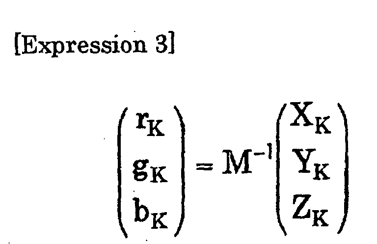
As shown in Fig. 7, first, the color of the illumination is represented in the
RGB of the projector in the calculation of the correction amounts for the color of
the illumination in S10 in Fig. 3 (S30). The color of the illumination
(corresponding to a value when the black of the projector is measured in the
application circumstances) is represented by the following equation when it is
represented in a mixture of the R, G, and B of the projector:
Then, the R,G and B values for a white point in the 3D-LUT is read out,
and luminance ratios of the R, G, and B values at the white point are obtained in
the calculation of the correction amounts for the color of the illumination in S10 in
Fig. 3 (S32). The R, G, and B values at the white point, rW0, gW0, and bW0, are:
rW0 ={R(255,0,0)/255}γ
gW0 ={G(0,255,0)/255}γ
bW0 ={B(0,0,255)/255}γ
γ is a value for representing an output gradation characteristic of the
projector, and is entered from the γ value input unit 116.
Based on the procedure above, offset correction amounts r0, g0, and b0 are
obtained in the calculation of the correction amounts of the illumination color in
S10 in Fig. 3 (S34).
As the following equation indicates, differences between rK, gK, and bK and
rW0, gW0, and bW0 are obtained so as to make them as the offset correction
amounts.
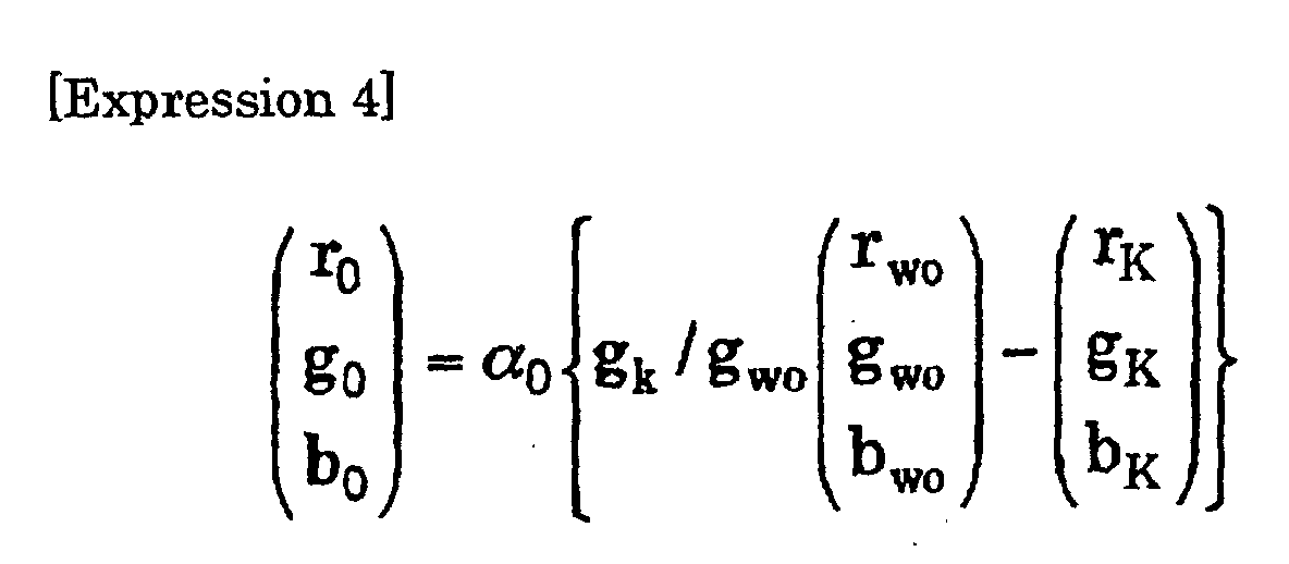
In the equation, α0 is a parameter for adjusting degree of applying the
correction, and a proper value for it ranges from 0.0 to 0.5.
This is the end of the processing in S10.
The following section describes calculation of the correction amounts for
the color of the screen in S12 in Fig. 3 while referring to Fig. 8. A change of an
output color characteristic of the projector due to the color of the screen is
corrected by correcting the gains of the individual RGB colors of the projector.
Specifically, a gain, which is for representing the white of the projector in the
reference circumstances by using the R, G, and B in the application circumstances,
is obtained.
In the calculation of the correction amounts for the color of the screen in
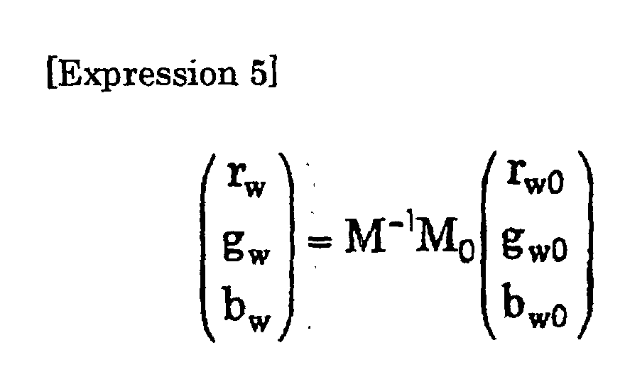
S12 in Fig. 3, as shown in Fig. 8, first, the color of the white of the projector (rw, gw,
bw) in the reference circumstances is represented by the R, G, and B of the
projector in the application circumstance (S40). Namely, luminance ratios of the
R, G, and B are obtained if the luminance ratios of the R, G, and B reproduce the
same color in the application circumstance with the white of the projector in the
reference circumstances as follows:
Then, gain correction amounts rG, gG, and bG are obtained in the
calculation of the correction amounts for the color of the screen in S12 in Fig. 3
(S42). The gain correction amounts are obtained as follows from rW, gW, and bW
and rW0, gW0, and bW0.
rG =1+αG {pr /max(pr , pg , pb )-1), pr =rW0 /rW
gG =1+αG {pg /max(pr , pg , pb )-1), pg =gW0 /gW
bG =1+αG {pb /max(pr , pg , pb )-1), pb =bW0 /bW
In the equation, αG is a parameter for adjusting degree of applying the
correction, and a proper value for it ranges from 0.5 to 1.0.
This is the end of the processing in S12.
The following section describes conversion of the values in the 3D-LUT in
S14 in Fig. 3 while referring to Fig. 9. In this processing, a correction
corresponding to a change of the circumstances is added to the output values for
the individual grid points of the 3D-LUT stored in the LUT data storage unit 114
to create a new correction table.
As shown in Fig. 9, the output values are read out from the individual grid
points in the 3D-LUT stored in the LUT data storage unit 114, and are converted
into luminance values in the conversion of the values in the 3D-LUT in S14 in Fig.
3 (S50). The converted luminance values (r), (g), and (b) are:
r={R(Rin, Gin, Bin)/255}γ
g={G(Rin, Gin, Bin)/255}γ
b={B(Rin, Gin, Bin)/255}γ
Then, circumstantial correction is applied in the conversion of the values
in the 3D-LUT in S14 in Fig. 3 (S52). The correction amounts obtained in S10
and S12 are used to correct the gain and the offset of the values in the 3D-LUT.
The values r', g', and b' after the correction are:
r'=rG r+r0
g'=gG g+g0
b'=bG b+b0
Then, a color outside the color gamut is processed in the conversion of the
values in the 3D-LUT in S14 in Fig. 3 (S54).
The values of r', g', and b' obtained in S52 may be outside the color gamut
(r'<0 or r'>1, for example) after the correction. When the values after the
correction are outside the color gamut, the correction amounts are adjusted such
that they stay inside the color gamut. The adjusting of the correction amounts is
performed while the R, G, and B are mutually correlated. Specifically, the
following equations are used to process the color outside the color gamut.
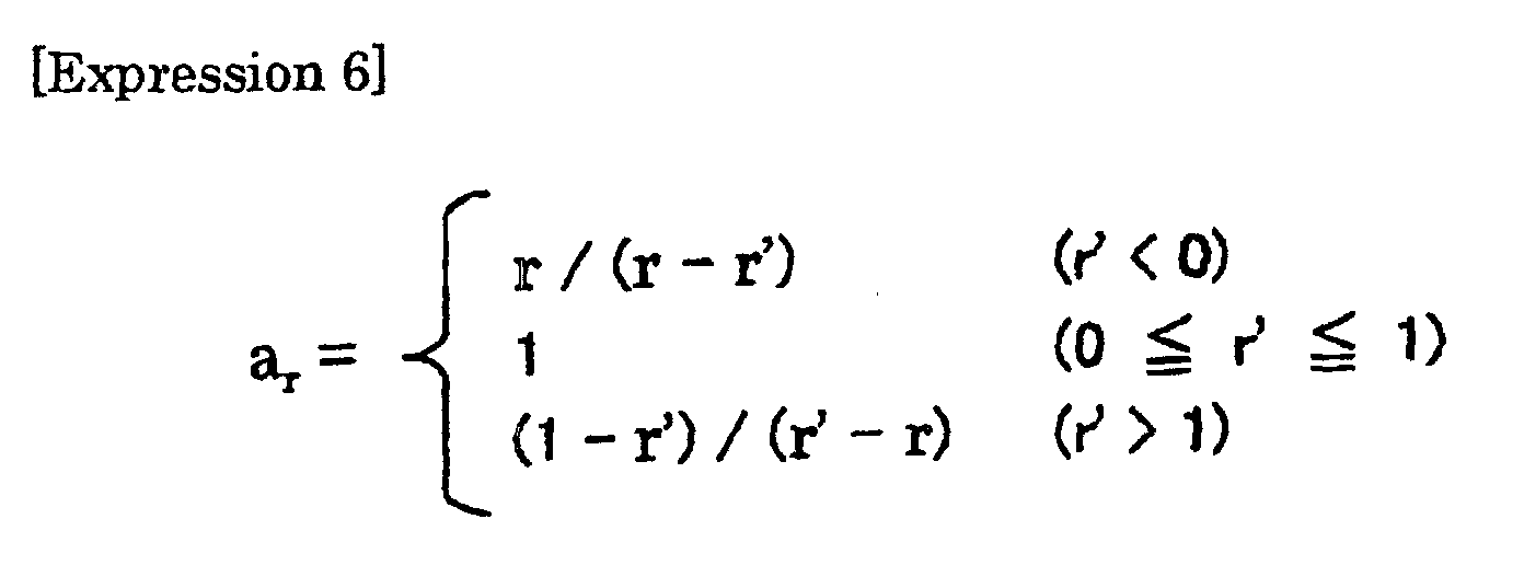
The same process applies to ag and ab

Further, the output values from the 3D-LUT after the circumstantial
correction are obtained in the conversion of the values in the 3D-LUT in S14 in
Fig. 3 (S56). The final output values R'(Rin, Gin, Bin), G'(Rin, Gin, Bin), and
B'(Rin, Gin, Bin) from the 3D-LUT added with corrections corresponding to the
circumstantial change are:
R'(Rin, Gin, Bin)=255(r")γ
G'(Rin, Gin, Bin)=255(g")γ
B'(Rin, Gin, Bin)=255(b")γ
This is the end of the processing in S14, and the procedure returns to
processing in the step 206 in Fig. 2.
The operation of the 2nd color corrector 120 in the projector according to
an embodiment of the present invention is similar to the operation of the 1st color
corrector 110 described while referring to Fig. 2. Thus, the following section
describes the operation of the 2nd color corrector 120 while referring to Fig. 2.
When the operation of the projector of the present invention starts, the
2nd color correction table generator 150 generates/rewrites the color correction
table (step 204). The following section details the generation/rewrite of the color
correction table while referring to Fig. 10. It is possible to synchronously or
independently conduct the generation/rewrite of the color correction table by the
1st color correction table generator 112 and the generation/rewrite of the color
correction table by the 2nd color correction table generator 150.
After generating/rewriting the color correction table, an image is displayed
based on an image signal with color correction by the 2nd color corrector 120 while
referring to the rewritten color correction table (step 206). When the image
display is not terminated (step 208, No), and a certain period has not passed since
the last generation/correction of the color correction table (step 210, No), the
display state of the image in the step 206 continues. On the other hand, when
the image display is not terminated (step 208, No), and the certain period has
passed since the last generation/correction of the color correction table (step 210,
Yes), the color correction table is generated/rewritten so as to correct the
gradation according to the application circumstances as time elapses (step 204),
and the image is displayed (step 206). With the present invention, since the color
correction table is rewritten at a certain time interval to correct the gradation
according to the application circumstances, proper color reproduction is enabled
even if the brightness of external illumination changes.
Then, when the display of the image is terminated by turning off the
projector (step 208, Yes), the processing ends.
The following section describes generation/rewrite of the color correction
table by the 2nd color correction table generator 150 (processing in the step 204 in
Fig. 2) in the projector according to an embodiment of the present invention while
referring to Fig. 10.
The projector (the image display device) 20 presents white (R=G=B=255 in
gradation) in a dark room in the generation/rewrite of the color correction table,
the optical sensor 170 measures the luminance of the reflected light from the
screen 10, and the result is stored in the device characteristic storage memory 160
in advance.
Then, the luminance of reflected light on the screen from the external
illumination is measured while the projector is not providing the output (step
222).
Then, a correction curve is calculated (step 226). The following section
details the calculation of the correction curve while referring to Fig. 11. Then, a
new one-dimensional color correction table is generated based on the calculated
correction curve. Then, the newly generated one-dimensional color correction
table replaces the one-dimensional color correction table referred from the color
corrector 120 (step 228).
The following section describes calculation of the correction curve by the
color correction table generator 150 in the projector (processing in the step 226 in
Fig. 10) according to an embodiment of the present invention while referring to
Fig. 11. The correction curve is obtained as follows based on the luminance of the
reflected light on the screen for the white output from the projector, which is
stored in the device characteristic storage memory 160, and the measured value
obtained in step 222 in Fig. 10.
In the correction curve calculation processing, γ curves are normalized
in different circumstances (step 230). Correction curves in all of W (white), R
(red), G (green), and B (blue) are the same curves, and therefore, in this
embodiment a correction curve is calculated with respect to W as an example. γ
curves in different circumstances (in a dark room and in an illuminated surround)
are assumed as follows. The "γ" represents a gradation characteristic of the
projector concerned. The value of γ is obtained by actually measuring the
gradation characteristic of the projector concerned and it is suitable to use a
average value as the value of γ. In this embodiment, γ is set equal to 2.2 as
an example.
In a dark room:
Fd(Din) = Yw · Dinγ
In an illuminated surround:
Fi(Din) = Yw · Dinγ + Yi
γ curves in different circumstances are shown in Fig. 12.
In the above equations, F represents a total luminance of lights reflected
by the screen, Din represents normalized values 0 - 1 by normalizing digital input
values (0 - 255 in gradation) of RGB, Yw represents the luminance of white of the
projector, and Yi represents the luminance of illumination. Then, the equations
(1) and (2) are normalized under the assumption that the eyes adapt themselves
to luminances (Yw in a dark room, Yw + Yi in an illuminated surround) detected
when the projector outputs white in different circumstances. That is, the
equations (1) and (2) are normalized so that the luminance (Yw in a dark room,
Yw + Yi in an illuminated surround) detected when the projector outputs white in
each of different circumstances becomes 1. More specifically:
In a dark room:
F'd(Din) = Fd(Din)/Yw = Dinγ
In an illuminated surround:
F'i(Din) = Fi(Din)/(Yw + Yi) = (Yw · Dinγ + Yi)/(Yw + Yi)
Normalizized γ curves in different circumstances are shown in Fig. 13.
Next, the γ curves are overlapped each other at a reference point Do (step
232). As shown in Fig. 14, F'd(Din) is shifted in parallel in F' axis direction by
only {F'i(Do) - F'd(Do)} so that F'd(Din) takes the same value as F'i(Din). More
specifically:
 If the equations (3) and (4) are used:
F"d(Din) = Dinγ -Doγ + (Yw · Doγ + Yi)/(Yw + Yi)
Then, using the equation (5), a correction curve is calculated (step 234).
Thus, in this embodiment, as shown in Fig. 14, a correction curve is
formed so that an output value of the γ curve in an illuminated surround
coincides with an output value of the γ curve in a dark room in the vicinity of the
reference point Do.
Then, the change in color of output image, which depends on whether an
external illumination is present or not, is diminished by correcting input
gradation values so that a relative contrast (gradient of γ curve) in the vicinity of
the reference point Do does not change depending on whether an external
illumination is present or not.
The above can be expressed by the following equation:
F'i(Dout) = F"d(Din)
where Dout represents input gradation values after correction.
Substitution of equations (4) and (5) for equation (6) gives:(Yw - Doutγ + Yi)/(Yw + Yi) = Dinγ -Doγ + (Yw · Doγ + Yi)/(Yw + Yi)
Thus,
Dout = [(1 + Yi/Yw)Dinγ -(Yi/Yw)Doγ ]1/γ
Substitution of equations (4) and (5) for equation (6) gives:
Note that since there is a limit for the luminance range for the output
(0≤F"d(Din)≤1) as shown in Fig. 15, correction is applied so as to provide an
output shown in Fig. 15.
Consequently, when Dout<0,
Dout=0, and
when Dout>1,
Dout=1.
Consequently, when Dout<0,
Dout=0, and
when Dout>1,
Dout=1.
The correction curve changes variously by changing the gradation Do
which serves as a main factor in correcting a lowering of contrast caused by
illumination. Generally, if the value of Do is small, there is obtained such a
correction curve as shown in Fig. 19, and although the gradation in a low gray
scale region is improved, the projection screen looks whitish, affording a light tone.
On the other hand, if the value of Do is made large, there is obtained such a
correction curve as shown in Fig. 20, in which the projection screen is blackish as
a whole and the gradation change in the low gray scale region further decreases
(what is called collapse of the low gray scale region becomes conspicuous). By
setting the value of Do at an appropriate value, it is possible to make such a
correction as contrast is most emphasized with little change in the entire
brightness of projected image as compared with that before correction. As a
result of experimental evaluation, it turned out that a Do value near a middle
gray scale (0.25≦D0≦0.50 or so) was suitable.
Further, as shown in Fig. 16, the amount of correction can be adjusted by
multiplying the amount of correction ΔF by α (0≦α≦1). This is for preventing
an unnatural image reproduction caused by an excessive correction. The
equation (7) of Dout in adjusting the amount of correction becomes as follows:
Dout = [(1 + αYi/Yw)Dinγ -(αYi/Yw)Doγ ]1/γ
Therefore, multiplying the amount of correction by α eventually corresponds to
multiplying the luminance of illumination, Yi, by α.
It is preferable that the value of α be within the range of 0.8≦α≦1.
Then the correction curve is rounded (step 236).
Fig. 17 shows a relationship between Dout and Din represented by an
equation (7) or equation (7') in Fig. 17. As Fig. 17 shows, though the correction
curve is constituted so as to emphasize the contrast as a whole, since the
gradation disappears around Dout=0 and Dout=1 on the color correction curve
shown in Fig. 17, the disappearance of the gradation around Dout=0 and Dout=1
is prevented by rounding the correction curve.
First, to perform where Dout stays at 0 or 1 without gradation, the
correction amount ΔD is reduced by converting the correction amount ΔD=Dout
-Din as follows.
ΔD → ΔD-(ΔD)β
With this conversion, since the reduction of the correction amount increases as the
correction amount becomes larger as shown in Fig. 18, the correction curve is
rounded consequently. β in the equation (8) is a parameter representing the
degree of the rounding, the rounding is not conducted when β=0, and Dout=Din
when β=∞. A preferable value for β is about 1.5. A curve (1) in Fig. 18
shows a relationship between Dout and Din when the rounding is applied to
reduce the correction amount.
Since a sharp angle remains on the correction curve (1) in Fig. 18,
averaging neighborhood is conducted for individual points further. Specifically,
the gradation data are calculated as 33 points (Din × 255=0, 8, 16, ..., 255), and
then, total of five points including previous and following two points are averaged
at the individual points. As a result of the process above, a correction curve is
generated without gradation where Dout stays at 0 or 1.
When the correction curve is calculated, four parameters comprising γ of
the projector, a reference point Do, a correction amount α, and the parameter for
rounding β are necessary. Various correction curves are generated with the
same calculation method by adjusting these values.
The following section describes the color correction by the 3rd corrector
130 while referring to Fig. 21.
The output characteristic of the projector is set as shown in Fig. 21(a), and
an input/output characteristic of the liquid crystal panel is measured as shown in
Fig. 21(b). Then, a correspondence between the input signal and the input value
to the liquid crystal panel is obtained based on the Fig. 21(a) and (b) as shown in
Fig. 21(c).
The 3rd color corrector 130 adjusts the input value to the liquid crystal
panel while referring to a color correction table representing the correspondence
between the input signal and the input value to the liquid crystal panel shown in
Fig. 21(c). The color correction tables are stored for the individual projectors in
advance.
Claims (13)
- An image display device for applying a desired image processing on inputted image data, and displaying an image, comprising:a 1st color correction unit for applying desired color correction to said inputted image data while referring to a three-dimensional color correction table so as to match a color characteristic of said image display device with a reference color characteristic based on a characteristic value of said image display device; anda 2nd color correction unit for applying desired color correction to said inputted image data while referring to a one-dimensional color correction table for correcting tone characteristic of said image display device in accordance with a surrounding environment.
- The image display device according to claim 1 further comprising a 1st rewriting unit for rewriting said three-dimensional color correction table so as to allow said 1st color correction unit to correct color characteristic of said image display device in accordance with a surrounding environment.
- The image display device according to claim 1 or 2 further comprising a 2nd rewriting unit for rewriting said three-dimensional color correction table so as to allow said 1st color correction unit to correct grid point data in said three-dimensional color correction table based on said characteristic value.
- The image display device according to one of claims 1-3, wherein the one-dimensional color correction table for said 2nd color correction unit is used for correction for a change of brightness of external illumination.
- The image display device according to one of claims 2-4, wherein the three-dimensional color correction table for said 1st color correction unit is used for correction for a change of color on a plane of projection.
- The image display device according to one of claims 2-5, wherein the three-dimensional color correction table for said 1st color correction unit is used for correction for a change of color of an external illumination.
- The image display device according to one of claims 1-6 further comprising a unit for entering said characteristic value.
- The image display device according to one of claims 1-7, wherein said image display device is a projector.
- The image display device according to one of claims 2-8, wherein said 2nd rewriting unit does not rewrite the grid point data when said characteristic value is a reference characteristic value.
- The image display device according to one of claims 2-8, wherein if said inputted image data are converted to the outside of a color gamut when the desired image processing is applied while referring to the three-dimensional color correction table rewritten by said 1st rewriting unit, said inputted image data are converted to the inside of the color gamut by reducing correction amounts while the ratio of changes of individual color components are maintained.
- An image processing method for applying a image processing on image data inputted to a display device, comprising:a 1st color correction step for applying desired color correction to said inputted image data while referring to a three-dimensional color correction table so as to match a color characteristic of said image display device with a reference color characteristic based on a characteristic value of said image display device; anda 2nd color correction step for applying desired color correction to said inputted image data while referring to a one-dimensional color correction table for correcting tone characteristic of said image display device in accordance with a surrounding environment.
- A program of instructions for execution by the computer to perform a image processing with respect to image data inputted to a display device, said program comprising:a 1st color correction processing for applying desired color correction to said inputted image data while referring to a three-dimensional color correction table so as to match a color characteristic of said image display device with a reference color characteristic based on a characteristic value of said image display device; anda 2nd color correction processing for applying desired color correction to said inputted image data while referring to a one-dimensional color correction table for correcting tone characteristic of said image display device in accordance with a surrounding environment.
- A computer-readable medium having the program according to claim 12.
Applications Claiming Priority (3)
| Application Number | Priority Date | Filing Date | Title |
|---|---|---|---|
| JP2002074245A JP3775666B2 (en) | 2002-03-18 | 2002-03-18 | Image display device |
| JP2002074245 | 2002-03-18 | ||
| PCT/JP2003/003065 WO2003079327A1 (en) | 2002-03-18 | 2003-03-14 | Image display apparatus, image processing method, program, and recording medium |
Publications (2)
| Publication Number | Publication Date |
|---|---|
| EP1486946A1 true EP1486946A1 (en) | 2004-12-15 |
| EP1486946A4 EP1486946A4 (en) | 2007-05-23 |
Family
ID=28035291
Family Applications (1)
| Application Number | Title | Priority Date | Filing Date |
|---|---|---|---|
| EP03708608A Withdrawn EP1486946A4 (en) | 2002-03-18 | 2003-03-14 | IMAGE DISPLAY APPARATUS, IMAGE PROCESSING METHOD, PROGRAM, AND RECORDING MEDIUM |
Country Status (11)
| Country | Link |
|---|---|
| US (1) | US7079155B2 (en) |
| EP (1) | EP1486946A4 (en) |
| JP (1) | JP3775666B2 (en) |
| KR (1) | KR100621285B1 (en) |
| CN (1) | CN100341045C (en) |
| AU (1) | AU2003213363A1 (en) |
| BR (1) | BR0303398A (en) |
| CA (1) | CA2447146A1 (en) |
| MX (1) | MXPA03010389A (en) |
| TW (1) | TWI231715B (en) |
| WO (1) | WO2003079327A1 (en) |
Cited By (2)
| Publication number | Priority date | Publication date | Assignee | Title |
|---|---|---|---|---|
| CN102054508B (en) * | 2009-11-09 | 2013-05-08 | 台达电子工业股份有限公司 | Multimedia playback system, device and method for identifying a file |
| CN103680467A (en) * | 2013-12-12 | 2014-03-26 | 京东方科技集团股份有限公司 | Method and device for processing image and display device |
Families Citing this family (40)
| Publication number | Priority date | Publication date | Assignee | Title |
|---|---|---|---|---|
| JP4652535B2 (en) * | 2000-07-25 | 2011-03-16 | キヤノン株式会社 | Image processing apparatus and method |
| JP2005328386A (en) * | 2004-05-14 | 2005-11-24 | Sharp Corp | White balance correction circuit setting system and method, LSI circuit used in the system, and liquid crystal television |
| CN100468517C (en) * | 2005-03-31 | 2009-03-11 | 华硕电脑股份有限公司 | Method and device for processing video signal |
| JP5087830B2 (en) * | 2005-09-09 | 2012-12-05 | セイコーエプソン株式会社 | Projection system |
| JP4882320B2 (en) * | 2005-09-09 | 2012-02-22 | セイコーエプソン株式会社 | Projection system, information processing apparatus, change image data generation method, change image data generation program, and recording medium on which this program is recorded |
| US20070081102A1 (en) * | 2005-10-11 | 2007-04-12 | Texas Instruments Incorporated | Apparatus and method for automatically adjusting white point during video display |
| CN101159878B (en) * | 2006-10-06 | 2011-07-13 | 台湾新力国际股份有限公司 | Color matching method, and image capturing apparatus and electronic device using the same |
| KR100843089B1 (en) * | 2006-10-17 | 2008-07-02 | 삼성전자주식회사 | Apparatus and method for improving the visibility of an image |
| KR100834764B1 (en) * | 2006-12-11 | 2008-06-05 | 삼성전자주식회사 | Image projection apparatus and method considering projection surface conditions |
| KR100830298B1 (en) * | 2007-01-03 | 2008-05-16 | 삼성에스디아이 주식회사 | Organic light emitting display device and driving method thereof |
| US9536463B2 (en) * | 2007-08-08 | 2017-01-03 | Landmark Screens, Llc | Method for fault-healing in a light emitting diode (LED) based display |
| US9659513B2 (en) * | 2007-08-08 | 2017-05-23 | Landmark Screens, Llc | Method for compensating for a chromaticity shift due to ambient light in an electronic signboard |
| US9262118B2 (en) * | 2007-08-08 | 2016-02-16 | Landmark Screens, Llc | Graphical display comprising a plurality of modules each controlling a group of pixels corresponding to a portion of the graphical display |
| US9342266B2 (en) * | 2007-08-08 | 2016-05-17 | Landmark Screens, Llc | Apparatus for dynamically circumventing faults in the light emitting diodes (LEDs) of a pixel in a graphical display |
| US9779644B2 (en) * | 2007-08-08 | 2017-10-03 | Landmark Screens, Llc | Method for computing drive currents for a plurality of LEDs in a pixel of a signboard to achieve a desired color at a desired luminous intensity |
| US9620038B2 (en) * | 2007-08-08 | 2017-04-11 | Landmark Screens, Llc | Method for displaying a single image for diagnostic purpose without interrupting an observer's perception of the display of a sequence of images |
| CN101123077B (en) * | 2007-09-10 | 2011-06-15 | 宏碁股份有限公司 | Image correction system and correction method for display device |
| TW200952503A (en) * | 2008-06-05 | 2009-12-16 | Delta Electronics Inc | Display apparatus, control module and method for the display apparatus |
| CN101635858B (en) * | 2008-07-23 | 2011-08-24 | 胜华科技股份有限公司 | Color correction method and integrated chip using it |
| TWI448917B (en) * | 2008-09-19 | 2014-08-11 | Hon Hai Prec Ind Co Ltd | System and method for computing and showing circularity |
| US8704848B2 (en) | 2009-04-21 | 2014-04-22 | Young Lighting Technology Inc. | Calibration system and method thereof for calibrating display |
| JP5326144B2 (en) * | 2009-04-21 | 2013-10-30 | 揚昇照明股▲ふん▼有限公司 | Calibration system and method for calibrating a display |
| JP2013504080A (en) | 2009-09-01 | 2013-02-04 | エンターテインメント イクスピアリアンス エルエルシー | Method for generating color image and imaging apparatus using the method |
| US8860751B2 (en) | 2009-09-01 | 2014-10-14 | Entertainment Experience Llc | Method for producing a color image and imaging device employing same |
| JP5877038B2 (en) * | 2010-11-19 | 2016-03-02 | 富士フイルム株式会社 | PROJECT DISPLAY METHOD AND DEVICE FOR PROJECTING IMAGE, FILM FOR PREPARATION, METHOD AND DEVICE FOR PRODUCING THE SAME, PROJECT METHOD FOR PROJECTING PROJECT IMAGE, PROGRAM, AND MOVIE SYSTEM |
| JP2013225722A (en) | 2012-04-19 | 2013-10-31 | Fujitsu Ltd | Information processing device, display control method, and display control program |
| CN102868892B (en) * | 2012-09-12 | 2015-07-08 | 苏州佳世达光电有限公司 | 3D (Three Dimensional)-mode color cast improving method |
| CN103810960B (en) * | 2012-11-07 | 2016-04-13 | 上海中航光电子有限公司 | Flat-panel monitor color data correcting device and method |
| JP2014155024A (en) * | 2013-02-07 | 2014-08-25 | Japan Display Inc | Color conversion device, display device, electronic apparatus, and color conversion method |
| DE102013206832A1 (en) * | 2013-04-16 | 2014-10-16 | Robert Bosch Gmbh | IMAGE DISPLAY DEVICE, MOBILE PHONE AND METHOD |
| KR102207464B1 (en) * | 2013-12-30 | 2021-01-27 | 삼성디스플레이 주식회사 | Display apparatus and driving method thereof |
| KR102158844B1 (en) | 2014-01-03 | 2020-09-22 | 삼성전자주식회사 | Apparatus and method for processing image, and computer-readable recording medium |
| CN105448230B (en) * | 2014-08-12 | 2017-11-17 | 西安诺瓦电子科技有限公司 | The bearing calibration of LED display bright chroma and system based on human eye vision |
| US10277783B2 (en) | 2014-11-14 | 2019-04-30 | Samsung Electronics Co., Ltd. | Method and device for image display based on metadata, and recording medium therefor |
| CN106162161A (en) * | 2016-07-05 | 2016-11-23 | 青岛海信电器股份有限公司 | A kind of image detecting method and display device |
| US11386588B2 (en) * | 2016-12-27 | 2022-07-12 | Sony Corporation | Product design system and design image correction apparatus |
| CN108848358B (en) * | 2018-05-31 | 2020-10-09 | 歌尔股份有限公司 | Method and device for correcting color convergence error |
| CN113495709B (en) * | 2020-03-20 | 2024-04-23 | 华为技术有限公司 | Color correction method, AP chip, terminal and storage medium |
| CN111770320B (en) * | 2020-07-14 | 2022-06-21 | 深圳市洲明科技股份有限公司 | Color correction method and device, color correction equipment and storage medium |
| CN116001460B (en) * | 2022-12-27 | 2025-12-02 | 北京奔图信息技术有限公司 | A dynamic calibration method and device for a color printer |
Family Cites Families (20)
| Publication number | Priority date | Publication date | Assignee | Title |
|---|---|---|---|---|
| JPH04136925A (en) | 1990-09-28 | 1992-05-11 | Sharp Corp | Liquid crystal projector |
| JP3268512B2 (en) * | 1993-03-03 | 2002-03-25 | セイコーエプソン株式会社 | Image processing apparatus and image processing method |
| KR0177937B1 (en) | 1994-08-04 | 1999-05-01 | 구자홍 | Automatic Image Correction Device and Method of Image Display Equipment |
| JPH1065930A (en) | 1996-08-19 | 1998-03-06 | Fuji Xerox Co Ltd | Color image processing method and color image processing unit |
| JPH10198793A (en) | 1997-01-14 | 1998-07-31 | Fuji Xerox Co Ltd | Image processor |
| GB2335326B (en) | 1997-10-31 | 2002-04-17 | Sony Corp | Image processing apparatus and method and providing medium. |
| JPH11175048A (en) | 1997-12-15 | 1999-07-02 | Fuji Xerox Co Ltd | Color image conversion coefficient calculation method and color image conversion method |
| JP3907810B2 (en) | 1998-01-07 | 2007-04-18 | 富士フイルム株式会社 | Three-dimensional lookup table correction method, image processing apparatus for performing the same, and digital color printer having the same |
| JP2001008045A (en) | 1999-06-23 | 2001-01-12 | Fuji Photo Film Co Ltd | Color signal processor |
| JP3691686B2 (en) | 1999-07-01 | 2005-09-07 | 富士通株式会社 | Color data conversion apparatus and color data conversion method |
| JP2002027272A (en) | 2000-07-11 | 2002-01-25 | Fuji Photo Film Co Ltd | Color chart and method for preparing color conversion definition |
| CN1179312C (en) * | 2000-07-19 | 2004-12-08 | 松下电器产业株式会社 | display method |
| US6847374B2 (en) | 2000-07-31 | 2005-01-25 | Seiko Epson Corporation | Environment-compliant image display system and program |
| JP3632574B2 (en) | 2000-07-31 | 2005-03-23 | セイコーエプソン株式会社 | Environment-adaptive image display system and information storage medium |
| US20020154138A1 (en) * | 2000-08-28 | 2002-10-24 | Osamu Wada | Environment adaptive image display system, image processing method and information storing medium |
| JP2002204374A (en) * | 2000-10-23 | 2002-07-19 | Seiko Epson Corp | Color correction table generation method, image processing device, image processing method, and recording medium |
| JP2002262304A (en) | 2001-03-06 | 2002-09-13 | Seiko Epson Corp | Image display device, image processing method, and program |
| JP3832626B2 (en) * | 2001-06-28 | 2006-10-11 | セイコーエプソン株式会社 | Image processing apparatus, image processing method, program, and recording medium |
| JP3841151B2 (en) * | 2001-06-28 | 2006-11-01 | セイコーエプソン株式会社 | Image processing apparatus, image processing method, program, and recording medium |
| JP4228620B2 (en) * | 2002-08-20 | 2009-02-25 | 富士ゼロックス株式会社 | Image forming apparatus |
-
2002
- 2002-03-18 JP JP2002074245A patent/JP3775666B2/en not_active Expired - Fee Related
-
2003
- 2003-03-13 US US10/386,433 patent/US7079155B2/en not_active Expired - Fee Related
- 2003-03-14 CA CA002447146A patent/CA2447146A1/en not_active Abandoned
- 2003-03-14 BR BR0303398-8A patent/BR0303398A/en not_active IP Right Cessation
- 2003-03-14 MX MXPA03010389A patent/MXPA03010389A/en unknown
- 2003-03-14 CN CNB038002701A patent/CN100341045C/en not_active Expired - Fee Related
- 2003-03-14 EP EP03708608A patent/EP1486946A4/en not_active Withdrawn
- 2003-03-14 AU AU2003213363A patent/AU2003213363A1/en not_active Abandoned
- 2003-03-14 KR KR1020037015039A patent/KR100621285B1/en not_active Expired - Fee Related
- 2003-03-14 WO PCT/JP2003/003065 patent/WO2003079327A1/en not_active Ceased
- 2003-03-17 TW TW092105806A patent/TWI231715B/en not_active IP Right Cessation
Cited By (3)
| Publication number | Priority date | Publication date | Assignee | Title |
|---|---|---|---|---|
| CN102054508B (en) * | 2009-11-09 | 2013-05-08 | 台达电子工业股份有限公司 | Multimedia playback system, device and method for identifying a file |
| CN103680467A (en) * | 2013-12-12 | 2014-03-26 | 京东方科技集团股份有限公司 | Method and device for processing image and display device |
| CN103680467B (en) * | 2013-12-12 | 2015-09-16 | 京东方科技集团股份有限公司 | Image processing method, device and display unit |
Also Published As
| Publication number | Publication date |
|---|---|
| KR100621285B1 (en) | 2006-09-13 |
| AU2003213363A1 (en) | 2003-09-29 |
| BR0303398A (en) | 2004-03-30 |
| US7079155B2 (en) | 2006-07-18 |
| TWI231715B (en) | 2005-04-21 |
| WO2003079327A1 (en) | 2003-09-25 |
| TW200306123A (en) | 2003-11-01 |
| US20030234794A1 (en) | 2003-12-25 |
| MXPA03010389A (en) | 2004-03-16 |
| JP2003271122A (en) | 2003-09-25 |
| EP1486946A4 (en) | 2007-05-23 |
| CA2447146A1 (en) | 2003-09-18 |
| KR20040005972A (en) | 2004-01-16 |
| CN1537304A (en) | 2004-10-13 |
| CN100341045C (en) | 2007-10-03 |
| JP3775666B2 (en) | 2006-05-17 |
Similar Documents
| Publication | Publication Date | Title |
|---|---|---|
| EP1486946A1 (en) | Image display apparatus, image processing method, program, and recording medium | |
| EP1391870B1 (en) | Image display system, projector, information storage medium and image processing method | |
| US7417643B2 (en) | Image processing system, projector, storage medium, and image processing method | |
| US8243210B2 (en) | Apparatus and method for ambient light adaptive color correction | |
| JP5157358B2 (en) | Image display system and image correction method | |
| EP1189457A2 (en) | Correction curve generating method, image processing method, image display unit and storage medium | |
| US6791565B2 (en) | Correction curve generating method, image processing method, image display unit, and storage medium | |
| JP2002262304A (en) | Image display device, image processing method, and program | |
| JP2003280629A (en) | Image display system, image processing method, program, and information storage medium | |
| US6940522B2 (en) | Correction curve generating method, image processing method, image display unit, and storage medium | |
| US6990234B2 (en) | Correction curve generating method, image processing method, image display unit, and storage medium | |
| JP4743424B2 (en) | Image display system, projector, program, and information storage medium | |
| JP2002202771A (en) | Image processing method, image display device, and recording medium | |
| KR101101328B1 (en) | Apparatus and method for color correction of video equipment according to ambient brightness | |
| US11862118B2 (en) | Display data processing device, image display system, and display data processing method | |
| JP2006033226A (en) | Tone correction device | |
| JP2019200266A (en) | Projection type display device | |
| JP2003230017A (en) | Image processing apparatus, image processing method, program, and recording medium |
Legal Events
| Date | Code | Title | Description |
|---|---|---|---|
| PUAI | Public reference made under article 153(3) epc to a published international application that has entered the european phase |
Free format text: ORIGINAL CODE: 0009012 |
|
| 17P | Request for examination filed |
Effective date: 20040223 |
|
| AK | Designated contracting states |
Kind code of ref document: A1 Designated state(s): AT BE BG CH CY CZ DE DK EE ES FI FR GB GR HU IE IT LI LU MC NL PT RO SE SI SK TR |
|
| A4 | Supplementary search report drawn up and despatched |
Effective date: 20070423 |
|
| 17Q | First examination report despatched |
Effective date: 20090605 |
|
| STAA | Information on the status of an ep patent application or granted ep patent |
Free format text: STATUS: THE APPLICATION IS DEEMED TO BE WITHDRAWN |
|
| 18D | Application deemed to be withdrawn |
Effective date: 20091216 |