EP1486926A1 - System and method for automatic crash notification - Google Patents
System and method for automatic crash notification Download PDFInfo
- Publication number
- EP1486926A1 EP1486926A1 EP03013297A EP03013297A EP1486926A1 EP 1486926 A1 EP1486926 A1 EP 1486926A1 EP 03013297 A EP03013297 A EP 03013297A EP 03013297 A EP03013297 A EP 03013297A EP 1486926 A1 EP1486926 A1 EP 1486926A1
- Authority
- EP
- European Patent Office
- Prior art keywords
- crash
- vehicle
- determining
- situation
- inferring
- Prior art date
- Legal status (The legal status is an assumption and is not a legal conclusion. Google has not performed a legal analysis and makes no representation as to the accuracy of the status listed.)
- Granted
Links
Images


Classifications
-
- B—PERFORMING OPERATIONS; TRANSPORTING
- B60—VEHICLES IN GENERAL
- B60R—VEHICLES, VEHICLE FITTINGS, OR VEHICLE PARTS, NOT OTHERWISE PROVIDED FOR
- B60R25/00—Fittings or systems for preventing or indicating unauthorised use or theft of vehicles
- B60R25/10—Fittings or systems for preventing or indicating unauthorised use or theft of vehicles actuating a signalling device
- B60R25/102—Fittings or systems for preventing or indicating unauthorised use or theft of vehicles actuating a signalling device a signal being sent to a remote location, e.g. a radio signal being transmitted to a police station, a security company or the owner
-
- B—PERFORMING OPERATIONS; TRANSPORTING
- B60—VEHICLES IN GENERAL
- B60R—VEHICLES, VEHICLE FITTINGS, OR VEHICLE PARTS, NOT OTHERWISE PROVIDED FOR
- B60R16/00—Electric or fluid circuits specially adapted for vehicles and not otherwise provided for; Arrangement of elements of electric or fluid circuits specially adapted for vehicles and not otherwise provided for
- B60R16/02—Electric or fluid circuits specially adapted for vehicles and not otherwise provided for; Arrangement of elements of electric or fluid circuits specially adapted for vehicles and not otherwise provided for electric constitutive elements
-
- G—PHYSICS
- G08—SIGNALLING
- G08B—SIGNALLING SYSTEMS, e.g. PERSONAL CALLING SYSTEMS; ORDER TELEGRAPHS; ALARM SYSTEMS
- G08B25/00—Alarm systems in which the location of the alarm condition is signalled to a central station, e.g. fire or police telegraphic systems
- G08B25/01—Alarm systems in which the location of the alarm condition is signalled to a central station, e.g. fire or police telegraphic systems characterised by the transmission medium
- G08B25/016—Personal emergency signalling and security systems
Definitions
- the present patent application relates to automatic crash notification and in particular a system for automatic crash notification for an automotive vehicle having improved crashworthiness in accordance with the preamble of claim 1.
- the present invention further relates to a method for automatic crash notification and in particular a method for automatic crash notification for an automotive vehicle providing improved crashworthiness in accordance with the preamble of claim 8.
- a crash notification system is offered in several car models.
- a crash notification system is usually triggered by the airbag system, supplementary restraint system or other system, in case of accident.
- the triggering system is directly connected to an emergency call module comprising a wireless communications means, such as a cellular phone or satellite radio.
- a message including position and other relevant information is sent to an alarm center.
- the position is normally acquired from a GPS receiver.
- the GPS receiver may be included in the emergency call module, a separate unit or be included in other systems such as a navigation system.
- a number of sensors are located about the vehicle, for example, air bag deployment sensors. Activation of the sensors to deploy the air bags also generates an emergency call activation signal upon detection of a vehicle accident.
- the emergency call activation signal is transmitted to an associated cellular telephone unit via wire line or non-wire line communications, and a timer initiates a timeout period. Once the timer has measured the proper timeout period, an emergency call setup is begun. The emergency call setup may be discontinued at any point by a user abort command. Otherwise, the mobile switching center serving the cellular telephone is alerted to initiate an emergency call.
- the mobile switching center utilizes location information from the base station of the cellular telephone and emergency information from the home location register of the cellular telephone to contact and provide an emergency operator with emergency information.
- a disadvantage with the arrangement known from the prior art mentioned above is that in case the wire line or wireless communications between the sensors and the cellular telephone is compromised, the system will fail to initiate an emergency call.
- a further disadvantage is that the provision of a dedicated wire line or wireless communications channel between the sensors and the cellular telephone adds to the cost and complexity of the system.
- a yet further disadvantage is that location information provided by the base station of the cellular telephone usually tend to be rather imprecise, which might make the task of locating the vehicle fairly cumbersome.
- One object of the invention is to provide an improved system for automatic crash notification and in particular an improved system for automatic crash notification in automotive vehicles providing for a highly crashworthy, low cost, platform independent crash notification system addressing the problems described in relation to the prior art arrangement.
- a standard vehicle bus e.g. a Controller Area Network (CAN) serial bus for initiating a crash notification message from sensors distributed in the vehicle without jeopardizing the crashworthiness while enabling the same hardware to be used in several different car models having such a vehicle bus.
- CAN Controller Area Network
- One further object of the invention is to provide an improved method for automatic crash notification and in particular an improved method for automatic crash notification in automotive vehicles providing for a highly crashworthy, low cost, platform independent crash notification method addressing the problems described in relation to the prior art arrangement.
- a vehicle bus such as a Controller Area Network (CAN) serial bus
- CAN Controller Area Network
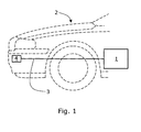
- Fig. 1 is simplified partial side view of a vehicle comprising a system for automatic crash notification
- Fig. 2 is a simplified block schematic of the system for automatic crash notification for an automotive vehicle
- Fig. 3 is a flow chart illustrating the method by which a crash notification message is initiated.
- FIG. 1 A simplified partial side view of a vehicle 2 comprising a system 1 for automatic crash notification is shown in figure 1.
- the system is connected to at least one crash sensor 4 arranged within said vehicle 2.
- the crash sensor 2 is arranged to communicate with the system 1 for automatic crash notification via an existing vehicle bus 3, such as a Controller Area Network (CAN) serial bus.
- CAN Controller Area Network
- the Controller Area Network is a serial communications protocol which efficiently supports distributed real-time control with a very high level of security. Its domain of application ranges from high speed networks to low cost multiplex wiring. In automotive electronics, engine control units, sensors, anti-skid-systems, etc. are connected using CAN with bit rates up to 1 Mbit/s. At the same time it is cost effective to build into vehicle body electronics, e.g. lamp clusters, electric windows etc. to replace the wiring harness otherwise required. This kind of bus is usually not redundant or crash proof, and it is therefore usually not sufficient to rely on as a sole system for triggering crash related events.
- Fig. 2 shows a simplified block schematic of the system 1 for automatic crash notification for an automotive vehicle.
- the system 1 comprises wireless communications means 5, such as a cellular phone or satellite radio or any other means for wireless communication which can be used to transmit information to e.g. a public telephone network or similar via an associated antenna (not shown) or similar.
- the system 1 optionally comprises means 6 for receiving data from a positioning system to derive positional information.
- These means 6 for receiving data from a positioning system can e.g. comprise means for receiving code sequences from global positioning system (GPS) satellites to derive said positional information or alternatively rely on positioning systems integrated in the cellular telephony network or similar systems enabling correct positioning of said vehicle 2.
- GPS global positioning system
- the system 1 further comprises means 7 for triggering communication of crash notification messages, said messages optionally comprising said positional information, using said wireless communications means 5, where said triggering means 7 are arranged to detect and characterize crash information provided to said vehicle bus 3 by at least one crash sensor 4 arranged within said vehicle 2.
- Said means 7 for triggering communication of crash notification messages further comprise means 8 for determining the operational status of said vehicle bus 3, and integrated means 9 for determining inferring a crash like situation and triggering communication of a crash notification message upon such determination if said vehicle bus 3 is determined to have suffered an unexpected malfunction or failure.
- said means 9 for determining inferring a crash like situation comprise means for computing the speed of said vehicle 2 based on said positional information and determining if said speed exceeds a predetermined first threshold value. If it is determined that the speed exceeds the predetermined first threshold value and the vehicle bus 3 is determined to have suffered an unexpected malfunction or failure, communication of a crash notification message is initiated.
- said means 9 for determining inferring a crash like situation comprise means for computing the speed of said vehicle 2 based on said positional information and determining if said speed exceeds a predetermined first threshold value and said speed is reduced from above said first threshold value to below a second predetermined threshold value within a predetermined time period. If the above is determined and the vehicle bus 3 is determined to have suffered an unexpected malfunction or failure, communication of a crash notification message is initiated.
- said means 9 for determining inferring a crash like situation is arranged to determine if the ignition of the vehicle 2 has been switched on and interpret subsequent determination that the vehicle bus 3 has suffered an unexpected malfunction or failure as a crash like situation and initiate communication of a crash notification message.
- said means 9 for determining inferring a crash like situation is arranged to determine if the ignition of the vehicle 2 has been switched on and the vehicle 2 thereafter has been in motion and interpret subsequent determination that said vehicle bus 3 has suffered an unexpected malfunction or failure as a crash like situation and initiate communication of a crash notification message.
- the means for computing and determination can be realized in software executable through said system 1 being provided with memory means and a micro controller means, such as a microprocessor.
- system 1 for automatic crash notification will be disabled if a plug is connected to a service connector of said vehicle, e.g. during service of said vehicle at a repair shop.
- communication of false crash notification messages during service of said vehicle 2 is avoided.
- FIG. 3 is a flow chart illustrating the method by which a crash notification message is initiated.
- Step 10 is a starting block at which the system waits for activation.
- step 11 which is optional, the system performs the step of receiving data from a positioning system to derive positional information.
- step 12 the operational status of a vehicle bus, such as a Controller Area Network (CAN) serial bus, is determined. If the operational status of the vehicle bus 3 is determined in step 12 to be operational, the flow is passed on to step 13 for the step of detecting and characterizing crash information provided to said vehicle bus 3 by at least one crash sensor 4 within said vehicle 2.
- CAN Controller Area Network
- step 14 the step of detecting and characterizing crash information provided by integrated means for determining inferring a crash like situation. If no crash information is detected in steps 13 or 14, the system is brought back to step 10 and the method repeated. If, on the other hand, crash information is detected in either of steps 13 or 14, communication of crash notification messages, optionally comprising said positional information, using wireless communications means are triggered.
- step 14 of determining inferring a crash like situation further comprises the steps of computing the speed of said vehicle based on said positional information and determining if said speed exceeds a predetermined first threshold value.
- the step 14 of determining inferring a crash like situation further comprises the steps of computing the speed of said vehicle based on said positional information and determining if said speed exceeds a predetermined first threshold value and determining if said speed is reduced from above said first threshold value to below a second predetermined threshold value within a predetermined time period.
- the step of receiving data from a positioning system to derive positional information further comprises receiving code sequences from global positioning system (GPS) satellites to derive said positional information.
- GPS global positioning system
- step 14 of determining inferring a crash like situation further comprises the steps of determining if the ignition of the vehicle has been switched on, and arranging said integrated means for determining inferring a crash like situation to interpret subsequent determination that said vehicle bus has suffered an unexpected malfunction or failure as a crash like situation.
- step 14 of determining inferring a crash like situation further comprises the steps of determining if the ignition of the vehicle has been switched on and the vehicle thereafter has been in motion, and arranging said integrated means for determining inferring a crash like situation to interpret subsequent determination that said vehicle bus has suffered an unexpected malfunction or failure as a crash like situation.
Landscapes
- Engineering & Computer Science (AREA)
- Mechanical Engineering (AREA)
- Computer Security & Cryptography (AREA)
- Business, Economics & Management (AREA)
- Emergency Management (AREA)
- Physics & Mathematics (AREA)
- General Physics & Mathematics (AREA)
- Traffic Control Systems (AREA)
Abstract
Description
- The present patent application relates to automatic crash notification and in particular a system for automatic crash notification for an automotive vehicle having improved crashworthiness in accordance with the preamble of
claim 1. - The present invention further relates to a method for automatic crash notification and in particular a method for automatic crash notification for an automotive vehicle providing improved crashworthiness in accordance with the preamble of claim 8.
- Automatic crash notification systems is offered in several car models. A crash notification system is usually triggered by the airbag system, supplementary restraint system or other system, in case of accident.
- The triggering system is directly connected to an emergency call module comprising a wireless communications means, such as a cellular phone or satellite radio. A message including position and other relevant information is sent to an alarm center. The position is normally acquired from a GPS receiver. The GPS receiver may be included in the emergency call module, a separate unit or be included in other systems such as a navigation system.
- One such system and method is previously known through US 6 073 004, in which is described a system and method for enabling emergency call initiations in response to the detection of a vehicle accident. A number of sensors are located about the vehicle, for example, air bag deployment sensors. Activation of the sensors to deploy the air bags also generates an emergency call activation signal upon detection of a vehicle accident. The emergency call activation signal is transmitted to an associated cellular telephone unit via wire line or non-wire line communications, and a timer initiates a timeout period. Once the timer has measured the proper timeout period, an emergency call setup is begun. The emergency call setup may be discontinued at any point by a user abort command. Otherwise, the mobile switching center serving the cellular telephone is alerted to initiate an emergency call. The mobile switching center utilizes location information from the base station of the cellular telephone and emergency information from the home location register of the cellular telephone to contact and provide an emergency operator with emergency information.
- A disadvantage with the arrangement known from the prior art mentioned above is that in case the wire line or wireless communications between the sensors and the cellular telephone is compromised, the system will fail to initiate an emergency call. A further disadvantage is that the provision of a dedicated wire line or wireless communications channel between the sensors and the cellular telephone adds to the cost and complexity of the system. A yet further disadvantage is that location information provided by the base station of the cellular telephone usually tend to be rather imprecise, which might make the task of locating the vehicle fairly cumbersome.
- One object of the invention is to provide an improved system for automatic crash notification and in particular an improved system for automatic crash notification in automotive vehicles providing for a highly crashworthy, low cost, platform independent crash notification system addressing the problems described in relation to the prior art arrangement.
- This object is achieved in accordance with the characterizing portion of
claim 1. - Thanks to the provision of means for determining the operational status of said vehicle bus, and integrated means for determining inferring a crash like situation and triggering communication of a crash notification message upon such determination if said vehicle bus is determined to have suffered an unexpected malfunction or failure it is possible to use a standard vehicle bus, e.g. a Controller Area Network (CAN) serial bus for initiating a crash notification message from sensors distributed in the vehicle without jeopardizing the crashworthiness while enabling the same hardware to be used in several different car models having such a vehicle bus.
- One further object of the invention is to provide an improved method for automatic crash notification and in particular an improved method for automatic crash notification in automotive vehicles providing for a highly crashworthy, low cost, platform independent crash notification method addressing the problems described in relation to the prior art arrangement.
- This object is achieved in accordance with the characterizing portion of claim 8.
- Thanks to the provision of steps for determining the operational status of a vehicle bus, such as a Controller Area Network (CAN) serial bus, and if said vehicle bus is determined to have suffered an unexpected malfunction or failure, detecting and characterizing crash information provided by integrated means for determining inferring a crash like situation it becomes possible to ensure triggering communication of crash notification messages without jeopardizing the crashworthiness while enabling use of the same hardware in several different car models utilizing such a vehicle bus.
- Preferred embodiments are listed in the dependent claims.
- In the following, the invention will be described in greater detail with reference to attached drawings, in which:
- Fig. 1 is simplified partial side view of a vehicle comprising a system for automatic crash notification,
- Fig. 2 is a simplified block schematic of the system for automatic crash notification for an automotive vehicle,
- Fig. 3 is a flow chart illustrating the method by which a crash notification message is initiated.
- Still other objects and features of the present invention will become apparent from the following detailed description considered in conjunction with the accompanying drawings. It is to be understood, however, that the drawings are designed solely for purposes of illustration and not as a definition of the limits of the invention, for which reference should be made to the appended claims. It should be further understood that the drawings are not necessarily drawn to scale and that, unless otherwise indicated, they are merely intended to conceptually illustrate the structures and procedures described herein.
- A simplified partial side view of a
vehicle 2 comprising asystem 1 for automatic crash notification is shown in figure 1. The system is connected to at least onecrash sensor 4 arranged within saidvehicle 2. Thecrash sensor 2 is arranged to communicate with thesystem 1 for automatic crash notification via an existingvehicle bus 3, such as a Controller Area Network (CAN) serial bus. - The Controller Area Network (CAN) is a serial communications protocol which efficiently supports distributed real-time control with a very high level of security. Its domain of application ranges from high speed networks to low cost multiplex wiring. In automotive electronics, engine control units, sensors, anti-skid-systems, etc. are connected using CAN with bit rates up to 1 Mbit/s. At the same time it is cost effective to build into vehicle body electronics, e.g. lamp clusters, electric windows etc. to replace the wiring harness otherwise required. This kind of bus is usually not redundant or crash proof, and it is therefore usually not sufficient to rely on as a sole system for triggering crash related events.
- Fig. 2 shows a simplified block schematic of the
system 1 for automatic crash notification for an automotive vehicle. Thesystem 1 comprises wireless communications means 5, such as a cellular phone or satellite radio or any other means for wireless communication which can be used to transmit information to e.g. a public telephone network or similar via an associated antenna (not shown) or similar. Thesystem 1 optionally comprises means 6 for receiving data from a positioning system to derive positional information. These means 6 for receiving data from a positioning system can e.g. comprise means for receiving code sequences from global positioning system (GPS) satellites to derive said positional information or alternatively rely on positioning systems integrated in the cellular telephony network or similar systems enabling correct positioning of saidvehicle 2. - The
system 1 further comprises means 7 for triggering communication of crash notification messages, said messages optionally comprising said positional information, using said wireless communications means 5, where said triggeringmeans 7 are arranged to detect and characterize crash information provided to saidvehicle bus 3 by at least onecrash sensor 4 arranged within saidvehicle 2. Said means 7 for triggering communication of crash notification messages further comprise means 8 for determining the operational status of saidvehicle bus 3, and integrated means 9 for determining inferring a crash like situation and triggering communication of a crash notification message upon such determination if saidvehicle bus 3 is determined to have suffered an unexpected malfunction or failure. - In one embodiment said means 9 for determining inferring a crash like situation comprise means for computing the speed of said
vehicle 2 based on said positional information and determining if said speed exceeds a predetermined first threshold value. If it is determined that the speed exceeds the predetermined first threshold value and thevehicle bus 3 is determined to have suffered an unexpected malfunction or failure, communication of a crash notification message is initiated. - In a further embodiment said means 9 for determining inferring a crash like situation comprise means for computing the speed of said
vehicle 2 based on said positional information and determining if said speed exceeds a predetermined first threshold value and said speed is reduced from above said first threshold value to below a second predetermined threshold value within a predetermined time period. If the above is determined and thevehicle bus 3 is determined to have suffered an unexpected malfunction or failure, communication of a crash notification message is initiated. - In a yet further embodiment said means 9 for determining inferring a crash like situation is arranged to determine if the ignition of the
vehicle 2 has been switched on and interpret subsequent determination that thevehicle bus 3 has suffered an unexpected malfunction or failure as a crash like situation and initiate communication of a crash notification message. - In a still further embodiment said means 9 for determining inferring a crash like situation is arranged to determine if the ignition of the
vehicle 2 has been switched on and thevehicle 2 thereafter has been in motion and interpret subsequent determination that saidvehicle bus 3 has suffered an unexpected malfunction or failure as a crash like situation and initiate communication of a crash notification message. - In the above described embodiments the means for computing and determination can be realized in software executable through said
system 1 being provided with memory means and a micro controller means, such as a microprocessor. - In all of the above embodiments it is envisaged that the
system 1 for automatic crash notification will be disabled if a plug is connected to a service connector of said vehicle, e.g. during service of said vehicle at a repair shop. Hereby, communication of false crash notification messages during service of saidvehicle 2 is avoided. - Figure 3 is a flow chart illustrating the method by which a crash notification message is initiated.
Step 10 is a starting block at which the system waits for activation. Instep 11, which is optional, the system performs the step of receiving data from a positioning system to derive positional information. Instep 12 the operational status of a vehicle bus, such as a Controller Area Network (CAN) serial bus, is determined. If the operational status of thevehicle bus 3 is determined instep 12 to be operational, the flow is passed on to step 13 for the step of detecting and characterizing crash information provided to saidvehicle bus 3 by at least onecrash sensor 4 within saidvehicle 2. If, on the other hand, the operational status is determined instep 12 to be that thevehicle bus 3 has suffered an unexpected malfunction or failure, the flow is passed on to step 14 for the step of detecting and characterizing crash information provided by integrated means for determining inferring a crash like situation. If no crash information is detected insteps steps - In a further embodiment the
step 14 of determining inferring a crash like situation further comprises the steps of computing the speed of said vehicle based on said positional information and determining if said speed exceeds a predetermined first threshold value. - In yet a further embodiment the
step 14 of determining inferring a crash like situation further comprises the steps of computing the speed of said vehicle based on said positional information and determining if said speed exceeds a predetermined first threshold value and determining if said speed is reduced from above said first threshold value to below a second predetermined threshold value within a predetermined time period. - In a still further embodiment the step of receiving data from a positioning system to derive positional information further comprises receiving code sequences from global positioning system (GPS) satellites to derive said positional information.
- In an additional embodiment the
step 14 of determining inferring a crash like situation further comprises the steps of determining if the ignition of the vehicle has been switched on, and arranging said integrated means for determining inferring a crash like situation to interpret subsequent determination that said vehicle bus has suffered an unexpected malfunction or failure as a crash like situation. - In yet an additional embodiment the
step 14 of determining inferring a crash like situation further comprises the steps of determining if the ignition of the vehicle has been switched on and the vehicle thereafter has been in motion, and arranging said integrated means for determining inferring a crash like situation to interpret subsequent determination that said vehicle bus has suffered an unexpected malfunction or failure as a crash like situation. - The invention is not limited to the above-described embodiments, but may be varied within the scope of the following claims.
- Thus, while there have been shown and described and pointed out fundamental novel features of the invention as applied to a preferred embodiment thereof, it will be understood that various omissions and substitutions and changes in the form and details of the devices illustrated, and in their operation, may be made by those skilled in the art without departing from the spirit of the invention. For example, it is expressly intended that all combinations of those elements and/or method steps which perform substantially the same function in substantially the same way to achieve the same results are within the scope of the invention. Moreover, it should be recognized that structures and/or elements and/or method steps shown and/or described in connection with any disclosed form or embodiment of the invention may be incorporated in any other disclosed or described or suggested form or embodiment as a general matter of design choice. It is the intention, therefore, to be limited only as indicated by the scope of the claims appended hereto.
Claims (15)
- A system (1) for automatic crash notification for an automotive vehicle, said system comprising:characterized in that said means (7) for triggering communication of crash notification messages further comprisewireless communications means (5),means (7) for triggering communication of crash notification messages using said wireless communications means, where said triggering means are arranged to detect and
characterize crash information provided to an existing vehicle bus (3), such as a Controller Area Network (CAN) serial bus, by at least one crash sensor within said vehicle,
means (8) for determining the operational status of said vehicle bus, and
integrated means (9) for determining inferring a crash like situation and triggering communication of a crash notification message upon such determination if said vehicle bus (3) is determined to have suffered an unexpected malfunction or failure. - A system (1) according to claim 1,
characterized in that said system further comprise means (6) for receiving data from a positioning system to derive positional information, and
in said means (7) for triggering communication of crash notification messages being arranged for triggering communication of crash notification messages comprising said positional information. - A system (1) according to any one of claim 2,
characterized in that said means (9) for determining inferring a crash like situation comprise means for computing the speed of said vehicle based on said positional information and determining if said speed exceeds a predetermined first threshold value. - A system (1) according to claim 3,
characterized in that said means (9) for determining inferring a crash like situation is arranged to determine if said speed is reduced from above said first threshold value to below a second predetermined threshold value within a predetermined time period. - A system (1) according to any one of claims 2 to 4,
characterized in that the means for receiving data from a positioning system comprise means for receiving code sequences from global positioning system (GPS) satellites to derive said positional information. - A system (1) according to any one of claims 1 to 5,
characterized in that said means (9) for determining inferring a crash like situation is arranged to determine if the ignition of the vehicle has been switched on and interpret subsequent determination that said vehicle bus (3) has suffered an unexpected malfunction or failure as a crash like situation. - A system (1) according to any one of claims 1 to 5,
characterized in that said means (9) for determining inferring a crash like situation is arranged to determine if the ignition of the vehicle has been switched on and the vehicle thereafter has been in motion and interpret subsequent determination that said vehicle bus (3) has suffered an unexpected malfunction or failure as a crash like situation. - A method for automatic crash notification for an automotive vehicle, characterized in that it comprises the steps of:determining the operational status of a vehicle bus, such as a Controller Area Network (CAN) serial bus,if said vehicle bus is determined to be operational, detecting and characterizing crash information provided to said vehicle bus by at least one crash sensor within said vehicle,if said vehicle bus is determined to have suffered an unexpected malfunction or failure, detecting and characterizing crash information provided by integrated means for determining inferring a crash like situation,triggering communication of crash notification messages using wireless communications means.
- A method according to claim 8,
characterized in that it further comprises the steps of:receiving data from a positioning system to derive positional information, andincluding into said crash notification messages said positional information. - A method according to any one of claim 9,
characterized in that it for determining inferring a crash like situation further comprises the steps of:computing the speed of said vehicle based on said positional information,determining if said speed exceeds a predetermined first threshold value. - A method according to claim 10,
characterized in that it for determining inferring a crash like situation further comprises the step of:determining if said speed is reduced from above said first threshold value to below a second predetermined threshold value within a predetermined time period. - A method according to any one of claims 9 to 11,
characterized in that the step of receiving data from a positioning system to derive positional information further comprises receiving code sequences from global positioning system (GPS) satellites to derive said positional information. - A method according to any one of claims 8 to 12,
characterized in that it for determining inferring a crash like situation further comprises the steps of:determining if the ignition of the vehicle has been switched on, andarranging said integrated means for determining inferring a crash like situation to interpret subsequent determination that said vehicle bus has suffered an unexpected malfunction or failure as a crash like situation. - A method according to any one of claims 8 to 12,
characterized in that it for determining inferring a crash like situation further comprises the steps of:determining if the ignition of the vehicle has been switched on and the vehicle thereafter has been in motion, andarranging said integrated means for determining inferring a crash like situation to interpret subsequent determination that said vehicle bus has suffered an unexpected malfunction or failure as a crash like situation. - An automotive vehicle,
characterized in that it comprises a system (1) according to any one of claims 1 to 7.
Priority Applications (2)
| Application Number | Priority Date | Filing Date | Title |
|---|---|---|---|
| EP20030013297 EP1486926B1 (en) | 2003-06-13 | 2003-06-13 | System and method for automatic crash notification |
| DE2003607242 DE60307242T2 (en) | 2003-06-13 | 2003-06-13 | System and method for an automatic accident reporting device |
Applications Claiming Priority (1)
| Application Number | Priority Date | Filing Date | Title |
|---|---|---|---|
| EP20030013297 EP1486926B1 (en) | 2003-06-13 | 2003-06-13 | System and method for automatic crash notification |
Publications (2)
| Publication Number | Publication Date |
|---|---|
| EP1486926A1 true EP1486926A1 (en) | 2004-12-15 |
| EP1486926B1 EP1486926B1 (en) | 2006-08-02 |
Family
ID=33185890
Family Applications (1)
| Application Number | Title | Priority Date | Filing Date |
|---|---|---|---|
| EP20030013297 Expired - Lifetime EP1486926B1 (en) | 2003-06-13 | 2003-06-13 | System and method for automatic crash notification |
Country Status (2)
| Country | Link |
|---|---|
| EP (1) | EP1486926B1 (en) |
| DE (1) | DE60307242T2 (en) |
Cited By (2)
| Publication number | Priority date | Publication date | Assignee | Title |
|---|---|---|---|---|
| FR2891687A1 (en) * | 2005-10-05 | 2007-04-06 | Peugeot Citroen Automobiles Sa | Emergency call sending method for motor vehicle, involves sending call request from gateway equipment to nomad equipment, and sending emergency call, including information relative to geographical position of vehicle, to assistance plate |
| CN118700957A (en) * | 2024-08-28 | 2024-09-27 | 安徽中科星驰自动驾驶技术有限公司 | A wire-controlled chassis for an autonomous vehicle |
Families Citing this family (3)
| Publication number | Priority date | Publication date | Assignee | Title |
|---|---|---|---|---|
| US8548686B2 (en) | 2007-10-11 | 2013-10-01 | Toyota Motor Sales, U.S.A., Inc. | Automatic crash notification using WiMAX |
| DE102013107658B4 (en) * | 2013-07-18 | 2016-10-13 | Matthias Borst | Warning triangle device |
| DE102023112859A1 (en) * | 2023-05-16 | 2024-11-21 | Bayerische Motoren Werke Aktiengesellschaft | Method for adapting a vehicle configuration, computer program, device and vehicle |
Citations (3)
| Publication number | Priority date | Publication date | Assignee | Title |
|---|---|---|---|---|
| DE3839959A1 (en) * | 1988-10-06 | 1990-04-12 | Bosch Gmbh Robert | EMERGENCY CALL DEVICE FOR A VEHICLE |
| DE19954822C1 (en) * | 1999-11-13 | 2001-09-06 | Daimler Chrysler Ag | Switching device for automobile emergency call signal transmitter has manually-operated switch element covered by plastics membrane for preventing accidental operation |
| DE10160292C1 (en) * | 2001-12-07 | 2002-12-05 | Audi Ag | Motor vehicle with automatic emergency position indicator, displays position information from navigation or position indication system in user interface if hazard warning system activated |
-
2003
- 2003-06-13 EP EP20030013297 patent/EP1486926B1/en not_active Expired - Lifetime
- 2003-06-13 DE DE2003607242 patent/DE60307242T2/en not_active Expired - Lifetime
Patent Citations (3)
| Publication number | Priority date | Publication date | Assignee | Title |
|---|---|---|---|---|
| DE3839959A1 (en) * | 1988-10-06 | 1990-04-12 | Bosch Gmbh Robert | EMERGENCY CALL DEVICE FOR A VEHICLE |
| DE19954822C1 (en) * | 1999-11-13 | 2001-09-06 | Daimler Chrysler Ag | Switching device for automobile emergency call signal transmitter has manually-operated switch element covered by plastics membrane for preventing accidental operation |
| DE10160292C1 (en) * | 2001-12-07 | 2002-12-05 | Audi Ag | Motor vehicle with automatic emergency position indicator, displays position information from navigation or position indication system in user interface if hazard warning system activated |
Cited By (2)
| Publication number | Priority date | Publication date | Assignee | Title |
|---|---|---|---|---|
| FR2891687A1 (en) * | 2005-10-05 | 2007-04-06 | Peugeot Citroen Automobiles Sa | Emergency call sending method for motor vehicle, involves sending call request from gateway equipment to nomad equipment, and sending emergency call, including information relative to geographical position of vehicle, to assistance plate |
| CN118700957A (en) * | 2024-08-28 | 2024-09-27 | 安徽中科星驰自动驾驶技术有限公司 | A wire-controlled chassis for an autonomous vehicle |
Also Published As
| Publication number | Publication date |
|---|---|
| DE60307242D1 (en) | 2006-09-14 |
| EP1486926B1 (en) | 2006-08-02 |
| DE60307242T2 (en) | 2007-07-05 |
Similar Documents
| Publication | Publication Date | Title |
|---|---|---|
| US7158016B2 (en) | Crash notification system for an automotive vehicle | |
| US6340928B1 (en) | Emergency assistance system using bluetooth technology | |
| JP3300705B2 (en) | In-vehicle communication terminal and information service center that communicates with the in-vehicle communication terminal | |
| JP3528440B2 (en) | In-vehicle information communication device | |
| US10037683B1 (en) | Crash detection using GNSS velocity measurements and bus monitoring | |
| US9730041B2 (en) | Emergency call sending system and method thereof | |
| US20050096007A1 (en) | Method and emergency call device for triggering an emergency call from a vehicle | |
| US20090261958A1 (en) | Low cost, automatic collision notification system and method of using the same | |
| CA2585899C (en) | Apparatus, and associated method, for generating an alert to notify emergency personnel of a vehicular emergency | |
| CN106160887A (en) | For the method and apparatus controlling the antenna in Vehicular system | |
| US20200307481A1 (en) | Airbag electronic controller unit | |
| JP2018533515A (en) | Device for identifying the accident situation of an open road vehicle | |
| JPH08287386A (en) | Vehicle accident notification system | |
| US20200134936A1 (en) | Information processing device and information processing method | |
| JPH10104258A (en) | Accident notifying system | |
| EP1486926B1 (en) | System and method for automatic crash notification | |
| JP2022053576A (en) | Vehicle with automatic notification function | |
| KR20170091288A (en) | Communication system and method between accident vehicles and other vehicles | |
| US20110291825A1 (en) | Car collision global positioning system | |
| KR102006590B1 (en) | WAVE and LTE integrated system and method for supporting Cooperative-Intelligent Transport Systems and Emergency Call service using the same | |
| JPH06251292A (en) | Vehicle current position information system | |
| KR100347610B1 (en) | Apparatus and method for automatically reporting car position in case of emergency | |
| JP2009003806A (en) | Emergency reporting system and portable terminal | |
| JP2000285347A (en) | Emergency call method and device and vehicle emergency call system | |
| KR20180043587A (en) | Emergency call system |
Legal Events
| Date | Code | Title | Description |
|---|---|---|---|
| PUAI | Public reference made under article 153(3) epc to a published international application that has entered the european phase |
Free format text: ORIGINAL CODE: 0009012 |
|
| 17P | Request for examination filed |
Effective date: 20040203 |
|
| AK | Designated contracting states |
Kind code of ref document: A1 Designated state(s): AT BE BG CH CY CZ DE DK EE ES FI FR GB GR HU IE IT LI LU MC NL PT RO SE SI SK TR |
|
| AX | Request for extension of the european patent |
Extension state: AL LT LV MK |
|
| AKX | Designation fees paid |
Designated state(s): DE GB SE |
|
| GRAP | Despatch of communication of intention to grant a patent |
Free format text: ORIGINAL CODE: EPIDOSNIGR1 |
|
| RAP1 | Party data changed (applicant data changed or rights of an application transferred) |
Owner name: FORD GLOBAL TECHNOLOGIES, LLC. |
|
| GRAS | Grant fee paid |
Free format text: ORIGINAL CODE: EPIDOSNIGR3 |
|
| GRAA | (expected) grant |
Free format text: ORIGINAL CODE: 0009210 |
|
| AK | Designated contracting states |
Kind code of ref document: B1 Designated state(s): DE GB SE |
|
| REG | Reference to a national code |
Ref country code: GB Ref legal event code: FG4D |
|
| REF | Corresponds to: |
Ref document number: 60307242 Country of ref document: DE Date of ref document: 20060914 Kind code of ref document: P |
|
| REG | Reference to a national code |
Ref country code: SE Ref legal event code: TRGR |
|
| PLBE | No opposition filed within time limit |
Free format text: ORIGINAL CODE: 0009261 |
|
| STAA | Information on the status of an ep patent application or granted ep patent |
Free format text: STATUS: NO OPPOSITION FILED WITHIN TIME LIMIT |
|
| 26N | No opposition filed |
Effective date: 20070503 |
|
| REG | Reference to a national code |
Ref country code: GB Ref legal event code: 732E Free format text: REGISTERED BETWEEN 20111020 AND 20111025 |
|
| REG | Reference to a national code |
Ref country code: DE Ref legal event code: R082 Ref document number: 60307242 Country of ref document: DE Representative=s name: LOUIS, POEHLAU, LOHRENTZ, DE |
|
| REG | Reference to a national code |
Ref country code: DE Ref legal event code: R082 Ref document number: 60307242 Country of ref document: DE Representative=s name: LOUIS, POEHLAU, LOHRENTZ, DE Effective date: 20120207 Ref country code: DE Ref legal event code: R081 Ref document number: 60307242 Country of ref document: DE Owner name: VOLVO CAR CORPORATION, SE Free format text: FORMER OWNER: FORD GLOBAL TECHNOLOGIES, LLC, DEARBORN, MICH., US Effective date: 20120207 |
|
| PGFP | Annual fee paid to national office [announced via postgrant information from national office to epo] |
Ref country code: SE Payment date: 20220519 Year of fee payment: 20 Ref country code: GB Payment date: 20220520 Year of fee payment: 20 Ref country code: DE Payment date: 20220518 Year of fee payment: 20 |
|
| REG | Reference to a national code |
Ref country code: DE Ref legal event code: R071 Ref document number: 60307242 Country of ref document: DE |
|
| REG | Reference to a national code |
Ref country code: GB Ref legal event code: PE20 Expiry date: 20230612 |
|
| REG | Reference to a national code |
Ref country code: SE Ref legal event code: EUG |
|
| PG25 | Lapsed in a contracting state [announced via postgrant information from national office to epo] |
Ref country code: GB Free format text: LAPSE BECAUSE OF EXPIRATION OF PROTECTION Effective date: 20230612 |
|
| REG | Reference to a national code |
Ref country code: DE Ref legal event code: R082 Ref document number: 60307242 Country of ref document: DE Representative=s name: ZACCO LEGAL RECHTSANWALTS GMBH, DE Ref country code: DE Ref legal event code: R081 Ref document number: 60307242 Country of ref document: DE Owner name: POLESTAR PERFORMANCE AB, SE Free format text: FORMER OWNER: VOLVO CAR CORPORATION, GOETEBORG, SE |