EP1486808A2 - Receptacle for optical fibre connection and method for its maufacture - Google Patents
Receptacle for optical fibre connection and method for its maufacture Download PDFInfo
- Publication number
- EP1486808A2 EP1486808A2 EP04077203A EP04077203A EP1486808A2 EP 1486808 A2 EP1486808 A2 EP 1486808A2 EP 04077203 A EP04077203 A EP 04077203A EP 04077203 A EP04077203 A EP 04077203A EP 1486808 A2 EP1486808 A2 EP 1486808A2
- Authority
- EP
- European Patent Office
- Prior art keywords
- ferrule
- inner part
- housing
- optical fiber
- optical
- Prior art date
- Legal status (The legal status is an assumption and is not a legal conclusion. Google has not performed a legal analysis and makes no representation as to the accuracy of the status listed.)
- Granted
Links
- 239000013307 optical fiber Substances 0.000 title claims abstract description 74
- 238000000034 method Methods 0.000 title claims description 8
- 230000003287 optical effect Effects 0.000 claims abstract description 105
- 210000000078 claw Anatomy 0.000 claims description 21
- RKTYLMNFRDHKIL-UHFFFAOYSA-N copper;5,10,15,20-tetraphenylporphyrin-22,24-diide Chemical compound [Cu+2].C1=CC(C(=C2C=CC([N-]2)=C(C=2C=CC=CC=2)C=2C=CC(N=2)=C(C=2C=CC=CC=2)C2=CC=C3[N-]2)C=2C=CC=CC=2)=NC1=C3C1=CC=CC=C1 RKTYLMNFRDHKIL-UHFFFAOYSA-N 0.000 claims description 15
- 238000004519 manufacturing process Methods 0.000 claims description 12
- 230000007246 mechanism Effects 0.000 claims description 9
- 230000002411 adverse Effects 0.000 abstract 1
- 238000010276 construction Methods 0.000 description 4
- 230000008878 coupling Effects 0.000 description 4
- 238000010168 coupling process Methods 0.000 description 4
- 238000005859 coupling reaction Methods 0.000 description 4
- 230000005540 biological transmission Effects 0.000 description 3
- 238000003466 welding Methods 0.000 description 3
- 230000009977 dual effect Effects 0.000 description 2
- 239000000835 fiber Substances 0.000 description 2
- 238000012986 modification Methods 0.000 description 2
- 230000004048 modification Effects 0.000 description 2
- 238000005452 bending Methods 0.000 description 1
- 230000008859 change Effects 0.000 description 1
- 239000011248 coating agent Substances 0.000 description 1
- 238000000576 coating method Methods 0.000 description 1
- 238000007796 conventional method Methods 0.000 description 1
- 230000000694 effects Effects 0.000 description 1
- 239000011521 glass Substances 0.000 description 1
- 239000000463 material Substances 0.000 description 1
- 231100000989 no adverse effect Toxicity 0.000 description 1
- 239000004033 plastic Substances 0.000 description 1
- 229920003023 plastic Polymers 0.000 description 1
- 239000000758 substrate Substances 0.000 description 1
Images


Classifications
-
- G—PHYSICS
- G02—OPTICS
- G02B—OPTICAL ELEMENTS, SYSTEMS OR APPARATUS
- G02B6/00—Light guides; Structural details of arrangements comprising light guides and other optical elements, e.g. couplings
- G02B6/24—Coupling light guides
- G02B6/36—Mechanical coupling means
- G02B6/38—Mechanical coupling means having fibre to fibre mating means
- G02B6/3807—Dismountable connectors, i.e. comprising plugs
- G02B6/389—Dismountable connectors, i.e. comprising plugs characterised by the method of fastening connecting plugs and sockets, e.g. screw- or nut-lock, snap-in, bayonet type
- G02B6/3893—Push-pull type, e.g. snap-in, push-on
-
- G—PHYSICS
- G02—OPTICS
- G02B—OPTICAL ELEMENTS, SYSTEMS OR APPARATUS
- G02B6/00—Light guides; Structural details of arrangements comprising light guides and other optical elements, e.g. couplings
- G02B6/24—Coupling light guides
- G02B6/36—Mechanical coupling means
- G02B6/38—Mechanical coupling means having fibre to fibre mating means
- G02B6/3807—Dismountable connectors, i.e. comprising plugs
- G02B6/381—Dismountable connectors, i.e. comprising plugs of the ferrule type, e.g. fibre ends embedded in ferrules, connecting a pair of fibres
- G02B6/3825—Dismountable connectors, i.e. comprising plugs of the ferrule type, e.g. fibre ends embedded in ferrules, connecting a pair of fibres with an intermediate part, e.g. adapter, receptacle, linking two plugs
-
- G—PHYSICS
- G02—OPTICS
- G02B—OPTICAL ELEMENTS, SYSTEMS OR APPARATUS
- G02B6/00—Light guides; Structural details of arrangements comprising light guides and other optical elements, e.g. couplings
- G02B6/24—Coupling light guides
- G02B6/36—Mechanical coupling means
- G02B6/38—Mechanical coupling means having fibre to fibre mating means
- G02B6/3807—Dismountable connectors, i.e. comprising plugs
- G02B6/3873—Connectors using guide surfaces for aligning ferrule ends, e.g. tubes, sleeves, V-grooves, rods, pins, balls
- G02B6/3874—Connectors using guide surfaces for aligning ferrule ends, e.g. tubes, sleeves, V-grooves, rods, pins, balls using tubes, sleeves to align ferrules
- G02B6/3877—Split sleeves
-
- G—PHYSICS
- G02—OPTICS
- G02B—OPTICAL ELEMENTS, SYSTEMS OR APPARATUS
- G02B6/00—Light guides; Structural details of arrangements comprising light guides and other optical elements, e.g. couplings
- G02B6/24—Coupling light guides
- G02B6/36—Mechanical coupling means
- G02B6/38—Mechanical coupling means having fibre to fibre mating means
- G02B6/3807—Dismountable connectors, i.e. comprising plugs
- G02B6/3897—Connectors fixed to housings, casing, frames or circuit boards
Definitions
- the present invention relates to an optical receptacle and a method for manufacturing the same. More. particularly, the present invention relates to an optical receptacle which is applied advantageously to connecting parts between a device having incorporated therein an input or output circuit, such as an ONU (optical network unit) module, and an optical fiber connector plug fitted to an outer optical cord as well as to a method for manufacturing the same.
- an input or output circuit such as an ONU (optical network unit) module
- an optical fiber connector plug fitted to an outer optical cord
- Optical connectors which are used for connecting optical fibers include IEC 1754-4 "Type SC Connector Family" prescribed in "JIS C-5973” (1990). This connector is generally called “SC-type optical fiber connector” and used widely in optical transmission systems.
- SC type optical fiber connectors couples detachably optical devices such as photo diodes (hereafter, sometimes referred to as "PD") or laser diodes (hereafter, sometimes referred to as "LD”) with optical fibers.
- Optical receptacles are optical components which connect the optical connectors with optical fiber connector plugs that are fitted on one hand to a device having input and output circuits for optical signals and on the other hand to an optical fiber connector plug.
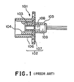
- FIG. 1 shows schematically a conventional "SC-type optical receptacle".
- a conventional optical receptacle 101 has an interface equivalent to an adapter in SC-type optical connectors.
- a housing 102 includes a substrate 107, to which a precision sleeve 103 is fixed, and a hook portion 104 and an outer shell 106. From a terminal end of the housing 102 are inserted a lens 108 and an optical element 109 such as PD or LD.
- the lens 108 and the optical element 109 are arranged coaxially with the center axis of the precision sleeve 103 so that the optical axis of an optical fiber is aligned to that of the element to which the optical fiber is to be connected.
- the precision sleeve 103 not only high precision alignment with the precision sleeve 103, the optical element 109 and so on is required but also the precision sleeve 103 itself must be fabricated with high precision, thus increasing the manufacturing cost of the optical receptacle.
- optical elements can be coupled with satisfactory working efficiency through fibers fitted to the optical elements in advance.
- an optical fiber is to be connected to an optical waveguide instead of an optical element itself, it is difficult to attach an optical receptacle directly to an end surface of the optical waveguide.
- optical connector there can be used widely the above-described SC-type optical fiber connectors.
- Fig. 2 is a partial cross sectional view showing a conventional SC-type optical fiber connector.
- Fig. 3 is an exploded view of a conventional SC-type optical fiber connector adapter and a conventional SC-type optical fiber connector plug, corresponding to the part A shown in Fig. 2.
- input and output portions of an optical module can be fabricated, for example, by attaching, to a tip portion of an optical fiber pigtail, an SC-type optical fiber connector 202 and connecting the SC-type optical fiber connector 208 to an SC-type optical fiber adapter 203 which is fitted to a panel portion of the optical module (not shown).
- the SC-type optical fiber adapter 203 has two housings 204 within each of which a sleeve 205 and hooks 206 are provided. In the sleeve 205 which is fitted in the housing 204 is held a split sleeve 211 as shown in Fig. 3.
- the optical fiber connector 208 includes the coupling device 202 one end of which can be fitted in the SC-type optical fiber adapter 203 and the other end thereof is inserted an outer shell 212.
- a ferrule 209 is pressed into the outer shell by a spring 213 which is supported by an inner shell 214 over which a crimp ring 215 covers.
- the crimp ring 215 together with an intervening ring 216 are contained in a boot 217, which is connected to the tension member and coating of an optical fiber cord 201.
- the outer shell 212, the ferrule 209, the spring 213, the inner shell 214, the crimp ring 215, the ring 216 are coaxially aligned and contained within the inner cavity of the coupling device 202..
- Connection to an optical fiber cable outside the optical module can be achieved by engaging the optical fiber connector plug 208 in the housing 204 such that the ferrule 209 is inserted in a split sleeve 211 and the housing 210 of the plug 208 to is clamped by the hooks 206 so that the plug 208 is prevented from rearward movement and thus does not come out of the housing 204.
- the SC-type optical fiber connector shown in Fig. 2 is of a dual engagement structure. More particularly, the ferrule 209 floats within the cavity of the plug housing 210. The plug housing 210 and the sleeve 205 engage with each other. On the other hand, the ferrule 209 and the split sleeve 211 engage with each other. The sleeve 205 and the split sleeve 211 engage with the respective counterparts independently of each other. Due to this dual engagement, the SC-type optical fiber connector is resistant to tension or bending urged to the optical cord from outside. If such an outer force is applied to the connector, the connector is given substantially no adverse effect on its connecting characteristics. As shown in Fig. 3, the conventional SC-type optical fiber adapter and the SC-type optical fiber connector plug together comprise thirteen (13) components. The SC-type optical fiber connector plug is prescribed
- SC-type optical fiber connectors are used under various conditions.
- the optical cord receives no outer force inside the optical module to which it is connected. Therefore, in such an environment where no outer force is urged, it is wasteful to use the above-described SC-type optical fiber connector.
- the use of SC-type optical fiber connectors is disadvantageous in view of production costs, space required for fitting it.
- An object of the present invention is to solve the above-described problems and provide an optical receptacle which is of a simple structure and less expensive as well as a method for manufacturing such an optical receptacle.
- the present invention provides an optical receptacle which comprises:
- the housing may comprise a fixing mechanism which fixes the inner part in position when the inner part is inlayed in the outer part.
- the housing may comprise a fixing mechanism which fixes the inner part in position when the inner part is inlayed in the outer part from a side where the first ferrule is positioned.
- the first ferrule may comprise a flange having an octagonal prism portion coaxial with the first ferrule and a tetragonal prism portion coaxial with the first ferrule continuing to the octagonal prism portion.
- the octagonal prism portion may engage with the first hook portions.
- the first hook portions may have respective claws; wherein the octagonal prism may have two parallel surfaces arranged along a longitudinal axis of the ferrule at a distance larger than a gap defined between inner surfaces of the claws of the first hook portions; and wherein the tetragonal prism portion may have two parallel surfaces at a distance is smaller than the gap between the inner surfaces of the claws of the first hook portions and a diagonal line of the tetragonal prism portion has a length which is equal to or larger than the distance between the two parallel surfaces of the octagonal prism portion.
- the diagonal line of the octagonal prism portion may have a length such that the first ferrule is allowed to rotate in the inner part of the housing.
- the present invention provides a method for manufacturing an optical receptacle as claimed in claim 1, which comprises the steps of:
- the inner part may be inserted in the outer part until a fixing mechanism provided in the housing fixes the inner part in position in the outer part.
- the present invention provides a housing for an optical receptacle, having a base end adapted for fitting a first ferrule and a nose end adapted for fitting an optical fiber connector plug, the housing comprising:
- the housing may comprise a fixing mechanism which fixes the inner part in position when the inner part is inlayed in the outer part.
- the housing may comprise a fixing mechanism which fixes the inner part in position when the inner part is inlayed in the outer part from a side where the first ferrule is positioned.
- the fixing mechanism may fix the inner part in position when the inner part is inlayed in the outer part from a side where the first ferrule is positioned.
- the present invention provides a method for manufacturing a housing for an optical receptacle as claimed in claim 1, comprising the steps of:
- the inner part may be inserted in the outer part until a fixing mechanism provided in the housing fixes the inner part in position in the outer part.
- the housing inlays the inner and outer parts therein to give a fixed structure so that no additional operation such as ultrasonic welding or the like is needed upon assembling the housing. This simplifies assembling operation greatly.
- the inner part can be inserted into the outer part from the side where a terminal or base end of the first ferrule is positioned in the outer part (cf. Figs. 8A and 8B) and inlayed and fixed in the outer part. As a result, even if undesirable tensile force is urged onto the optical fiber cable to which the first ferrule is attached, the inlayed portion of the inner part will not disengage from and come out of the outer part.
- the first ferrule has a flange of an octagonal prism in shape coaxial with the axis of the first ferrule.
- the octagonal prism continues to a tetragonal prism coaxial with the axis of the first ferrule.
- the first hooks engage with the octagonal prism, two opposite parallel side surfaces of the octagonal prism are spaced apart from each other at a distance which is larger than the gap between the inner surfaces of the claws of the first hooks.
- the two opposite parallel side surfaces of the tetragonal prism are spaced apart from each other at a distance is smaller than the gap between the inner surfaces of the claws of the first hooks.
- the diagonal line has a length equal to or slightly greater than the distance between the parallel side surfaces of the octagonal prism.
- the first ferrule held at the base portion of the housing by the first hooks is fitted in a split sleeve while in the optical fiber connector plug connected to the housing at its nose end, the second ferrule is fitted in the split sleeve so that it is aligned and held at the position of fitting by the second hooks.
- the first hooks for engaging with the first ferrule and the second hooks for engaging with the optical fiber connector plug are molded integrally (i.e., solidly or as one-piece) as an inner part so that the relationship between the positions of the first and second ferrules at the time of coupling can readily be maintained with high precision without high precision assembling operations.
- a spring which has been conventionally required to press the first ferrule may be eliminated. Without springs, the first and second ferrules to be connected can firmly be pressed against each other so that the reliability in connecting characteristics can be increased.
- the split sleeve can reach to the foot of the flange of the first ferrule so that a shorter ferrule can be used, with the result that when ferrules are manufactured less grinding of the outer surfaces of the ferrule is required. Therefore, the optical receptacle can be manufactured at low cost.
- the split sleeve is drawn out simultaneously so that less friction occurs between the first ferrule and the split sleeve. Therefore, inexpensive materials with low friction resistance,such as glass and plastics can be put in practical use for the ferrule.
- optical receptacle is designed to connect optical transmission components and for this purpose is attached to one of the components.
- an optical receptacle 10 includes a housing 11, a split sleeve 30 and a ferrule 40 to one end of which the split sleeve 30 is connected.
- the housing 11 is capable of containing the split sleeve 30 and a part of the ferrule 40.
- the housing 11 is in form and includes an outer part 12 and an inner part 13 which is inserted into the outer part 12. At a terminal of the inner part 13 is provided a fitting portion 14 on whose inner surface a flange 42 of the first ferrule 40 fitted (Fig. 5). Above and below the fitting part 14 are arranged a pair of first hooks 15 having respective first claws 16 on the tips thereof. The first hooks 15 with the first claws 16 hold the flange 42 of the first ferrule 40 in position (Fig. 4).
- a key way 23 for holding the optical fiber connector 51 having a key 54 and receives the key 54 (Figs. 5 and 6).
- a fitting flange 19 formed of fitting holes 24 through which screws or the like fitting means are inserted to fix the housing to an optical module (not shown) in position (Figs. 4 and 6).
- split sleeve 30 On the inner surface of the inner part 13 a split sleeve 30 is fitted. In the split sleeve 30 are fitted on one hand the first ferrule 41 which is fitted from the side of the bottom end of the inner part 13, or from right to left in Fig. 4, and on the other hand the second ferrule 52 of the optical fiber connector plug 51 to be connected (Fig. 12). Thus, the split sleeve 30 allow the first and second ferrules 40 and 52 to align in the axial direction (Fig. 12).
- the housing 11 is constructed.
- the inner part 13 has first protrusions 20 on its upper and lower surfaces while the outer part 12 has on its inner surface a second protrusion 21 and a step 22.
- the inner part 13 is inserted into the outer part 12 from the side of the base end of the housing 11 until the first protrusions 20 pass by the second protrusion 21 against an inward force urged to the inner part 13 by a slightly constricted inner diameter of the cavity. As soon as the first protrusions pass by the second protrusion 21, a portion of the inner part 13 abuts the step 22 provided on the inner surface of the outer part 12 and thus is fixed.
- the inner part 13 and the outer part 12 contact each other along a sufficient are so that the inner part 13 will not come out of the outer part 12 if an excess or otherwise intolerable external force such as a tensile force is urged to the inner part 13. Therefore, there is no danger that the optical fiber connector plug 51 together with the inner part 13 and the first ferrule 40 is drawn out of the optical module to thereby break the device.
- the first hooks 15 and second hooks 17 are molded integrally as the inner part 13. This construction is advantageous in that the relative positions of the first and second hooks can be set with higher precision and assembling operation is more simple as compared with the conventional method in which the both first and second hooks are fabricated separately and subsequently assembled as by ultrasonic welding.
- the flange 42 of the first ferrule 40 is configured to a shape of a combination of an octagonal prism 43 coaxially connected to a tetragonal prism 44.
- the distance between two opposing parallel surfaces of the tetragonal prism 44 is made smaller than the distance between the second claws 16 themselves.
- the diagonal line of the tetragonal prism 44 has a length of L 1 while the distance between the parallel two surfaces of the octagonal prism is L 2 .
- the length, L 1 , of the diagonal line of the tetragonal prism 44 is the same as or slightly larger than the distance, L 2 , the opposite end points 45 and 46 of the diagonal line contact the inner surface of the first claws 16 when the ferrule 40 is rotated about its longitudinal axis at angles of 45° so that the distance between the opposing first claws 16 is made greater than the two parallel surfaces of the octagonal prism.
- the first ferrule 40 is released and can be readily put out of the inner part 13 of the optical receptacle 10.
- the first ferrule 40 is rotated under the conditions that the second ferrule 52 still contacts on its end surface the end surface of the first ferrule 40, the end surface of the optical fiber in the ferrule tends to be damaged. Accordingly, when the second ferrule 52 is to be taken out of the inner part 13, care must be taken to check to see if the optical fiber connector plug is disconnected from the optical receptacle of the present invention.
- Connection of optical transmission components to each other through the optical receptacle 10 according to the first embodiment of the present invention can be achieved by inserting the optical fiber connector plug 51 into the optical receptacle 10 from its left hand side as seen in Fig. 12 so. that the optical fiber 45 fitted to the first ferrule 40 and the optical fiber cable 53 fitted to the second ferrule 52 are aligned.
- This embodiment is the second embodiment of the optical receptacle of the present invention.
- Fig. 14 is an right end view showing an optical receptacle according to the second embodiment of the present invention.
- Fig. 15 is the first ferrule according to the first embodiment of the present invention.
- Fig. 16 is a right end view showing the first ferrule shown in Fig. 15.
- the optical receptacle according to this embodiment differ from that of the first embodiment of the present invention in the configuration of the flange.
- the first ferrule 40 in the present embodiment has a flange 43a which engages with the first claws 16 and is of a tetragonal prism instead of the octagonal prism that is used in the first ferrule according to the first embodiment of the present invention as shown in Fig. 9.
- the ferrule according to this embodiment of the present invention cannot rotate unlike the first ferrule according to the first embodiment of the present invention described above and, hence, the first ferrule with the tetragonal flange 43a cannot be taken out of the housing 11 by a mere operation, such as rotation about its longitudinal axis, of the first ferrule 40 itself.
- the flange 43a must be disengaged from the first claws 16 of the first hooks 15. This can be achieved by broadening the gap between the first claws 16 by a suitable means.
- a jig in the form of a plate for example can be inserted in the gap between one of the claws 16 and the tetragonal prism 44.
- the jig may be of any desired shape as far as it has two plate-like members such as the plates described above.
- commonly available tools such as tweezers may also be used for the disengagement of the ferrule from the inner part 13 of the optical receptacle according to this embodiment of the present invention.
- the first ferrule 40 never rotates around its longitudinal axis so that no erroneous or harmful operation can occur such that the end face of the optical fiber is damaged by rotation of the first ferrule 40 which contacts the end face of the optical fiber.
- FIG. 17 is a schematic perspective view showing an eight-component-array optical receptacle comprising eight receptacles according to the first embodiment of the present invention integrally assembled side by side.
- the configurations of the first and second ferrules are the same as those of the first and second ferrules in the optical receptacle according to the first or second embodiment of the present invention.
- the array housing 70 is an integrally molded article comprising eight single housings integrally combined arranged in parallel side by side.
- the inner part 13 may be the same as that used in the optical receptacle 10 according to the first embodiment of the present invention. Accordingly, it is sufficient to change the configuration of only the outer part that is simple in structure and inexpensive. Therefore, the optical receptacle according to this embodiment can be realized at low costs as compared with the case where the entire structure has to be newly produced.
- eight-component-array optical receptacle may be realized as a compact article using as an optical fiber connector plug to be connected a high density type SC connector plug 208a having a structure in which the plug is removed with a jig or removing tool after the coupling device is detached from the SC-type optical fiber connector plug.
- This embodiment relates to the manufacture of the housing of the optical receptacle according to any one of EMBODIMENT 1 TO 3 above.
- Fig. 18 is a cross sectional view showing inner and outer parts of an optical receptacle to be assembled, illustrating the step of manufacturing the housing of an optical receptacle according to any one of the foregoing embodiments of the present invention.
- the outer part 12 and the inner part 13 which are components of the housing 11 are separately prepared as integral molded articles, respectively.
- the inner part 13 is inserted in the outer part 12 until the protrusions 21 provided in the inner surface of the outer part 12 engage with the protrusions 20 of the inner part 13 so that the inner part 13 is held fixedly in the outer part 12.
- the housing thus formed requires no further operation such as ultrasonic welding for bonding these components before it is assembled with the same first ferrule used in the optical receptacle according to any one of the foregoing embodiments.
Landscapes
- Physics & Mathematics (AREA)
- General Physics & Mathematics (AREA)
- Optics & Photonics (AREA)
- Mechanical Coupling Of Light Guides (AREA)
- Optical Couplings Of Light Guides (AREA)
Abstract
Description
- The present invention relates to an optical receptacle and a method for manufacturing the same. More. particularly, the present invention relates to an optical receptacle which is applied advantageously to connecting parts between a device having incorporated therein an input or output circuit, such as an ONU (optical network unit) module, and an optical fiber connector plug fitted to an outer optical cord as well as to a method for manufacturing the same.
- Optical connectors which are used for connecting optical fibers include IEC 1754-4 "Type SC Connector Family" prescribed in "JIS C-5973" (1990). This connector is generally called "SC-type optical fiber connector" and used widely in optical transmission systems. At their input and output portions for inputting and outputting optical signals, SC type optical fiber connectors couples detachably optical devices such as photo diodes (hereafter, sometimes referred to as "PD") or laser diodes (hereafter, sometimes referred to as "LD") with optical fibers. Optical receptacles are optical components which connect the optical connectors with optical fiber connector plugs that are fitted on one hand to a device having input and output circuits for optical signals and on the other hand to an optical fiber connector plug.
- Fig. 1 shows schematically a conventional "SC-type optical receptacle". As shown in Fig. 1, a conventional
optical receptacle 101 has an interface equivalent to an adapter in SC-type optical connectors. Ahousing 102 includes asubstrate 107, to which aprecision sleeve 103 is fixed, and ahook portion 104 and anouter shell 106. From a terminal end of thehousing 102 are inserted alens 108 and anoptical element 109 such as PD or LD. - In the case of the above-described conventional optical receptacle, the
lens 108 and theoptical element 109 are arranged coaxially with the center axis of theprecision sleeve 103 so that the optical axis of an optical fiber is aligned to that of the element to which the optical fiber is to be connected. When a single mode optical fiber is used, not only high precision alignment with theprecision sleeve 103, theoptical element 109 and so on is required but also theprecision sleeve 103 itself must be fabricated with high precision, thus increasing the manufacturing cost of the optical receptacle. - On the other hand, it is sometimes the case that optical elements can be coupled with satisfactory working efficiency through fibers fitted to the optical elements in advance. In the case where an optical fiber is to be connected to an optical waveguide instead of an optical element itself, it is difficult to attach an optical receptacle directly to an end surface of the optical waveguide.
- In order to connect a pig-tail optical fiber, which is fitted to an optical circuit, to an optical cord detachably, it is advantageous to attach an optical connector to each optical fiber and connect the fibers through an adapter since this approach is most excellent in workability and gives good connection characteristics.
- As such an optical connector, there can be used widely the above-described SC-type optical fiber connectors.
- Fig. 2 is a partial cross sectional view showing a conventional SC-type optical fiber connector. Fig. 3 is an exploded view of a conventional SC-type optical fiber connector adapter and a conventional SC-type optical fiber connector plug, corresponding to the part A shown in Fig. 2.
- As shown in Fig. 2, input and output portions of an optical module can be fabricated, for example, by attaching, to a tip portion of an optical fiber pigtail, an SC-type
optical fiber connector 202 and connecting the SC-typeoptical fiber connector 208 to an SC-typeoptical fiber adapter 203 which is fitted to a panel portion of the optical module (not shown). In this case, the SC-typeoptical fiber adapter 203 has twohousings 204 within each of which asleeve 205 andhooks 206 are provided. In thesleeve 205 which is fitted in thehousing 204 is held asplit sleeve 211 as shown in Fig. 3. Theoptical fiber connector 208 includes thecoupling device 202 one end of which can be fitted in the SC-typeoptical fiber adapter 203 and the other end thereof is inserted anouter shell 212. Aferrule 209 is pressed into the outer shell by aspring 213 which is supported by aninner shell 214 over which acrimp ring 215 covers. Thecrimp ring 215 together with an interveningring 216 are contained in aboot 217, which is connected to the tension member and coating of anoptical fiber cord 201. Theouter shell 212, theferrule 209, thespring 213, theinner shell 214, thecrimp ring 215, thering 216 are coaxially aligned and contained within the inner cavity of thecoupling device 202.. - Connection to an optical fiber cable outside the optical module can be achieved by engaging the optical
fiber connector plug 208 in thehousing 204 such that theferrule 209 is inserted in asplit sleeve 211 and thehousing 210 of theplug 208 to is clamped by thehooks 206 so that theplug 208 is prevented from rearward movement and thus does not come out of thehousing 204. - As described above, the SC-type optical fiber connector shown in Fig. 2 is of a dual engagement structure. More particularly, the
ferrule 209 floats within the cavity of theplug housing 210. Theplug housing 210 and thesleeve 205 engage with each other. On the other hand, theferrule 209 and thesplit sleeve 211 engage with each other. Thesleeve 205 and thesplit sleeve 211 engage with the respective counterparts independently of each other. Due to this dual engagement, the SC-type optical fiber connector is resistant to tension or bending urged to the optical cord from outside. If such an outer force is applied to the connector, the connector is given substantially no adverse effect on its connecting characteristics. As shown in Fig. 3, the conventional SC-type optical fiber adapter and the SC-type optical fiber connector plug together comprise thirteen (13) components. The SC-type optical fiber connector plug is prescribed - As is well known, SC-type optical fiber connectors are used under various conditions. For example, in some applications, the optical cord receives no outer force inside the optical module to which it is connected. Therefore, in such an environment where no outer force is urged, it is wasteful to use the above-described SC-type optical fiber connector. Much less, the use of SC-type optical fiber connectors is disadvantageous in view of production costs, space required for fitting it.
- An object of the present invention is to solve the above-described problems and provide an optical receptacle which is of a simple structure and less expensive as well as a method for manufacturing such an optical receptacle.
- According to the first aspect, the present invention provides an optical receptacle which comprises:
- a housing having a base end and a nose end, the housing comprising an inner part and an outer part having fixed therein the inner part;
- a first ferrule fitted to the base end of the housing; wherein the inner part comprises:
- a sleeve for fitting with alignment to the first ferrule and a second ferrule in an optical fiber connector to be connected to the nose end of the housing;
- first hook portions for holding the first ferrule provided at the base end of the housing;
- second hook portions for holding the optical fiber connector plug at a fitting position of the optical fiber connector plug;
- the first and second hook portions being parts of an integral molded, article.
-
- Here, the housing may comprise a fixing mechanism which fixes the inner part in position when the inner part is inlayed in the outer part.
- The housing may comprise a fixing mechanism which fixes the inner part in position when the inner part is inlayed in the outer part from a side where the first ferrule is positioned.
- The first ferrule may comprise a flange having an octagonal prism portion coaxial with the first ferrule and a tetragonal prism portion coaxial with the first ferrule continuing to the octagonal prism portion.
- The octagonal prism portion may engage with the first hook portions.
- The first hook portions may have respective claws;
wherein the octagonal prism may have two parallel surfaces arranged along a longitudinal axis of the ferrule at a distance larger than a gap defined between inner surfaces of the claws of the first hook portions; and
wherein the tetragonal prism portion may have two parallel surfaces at a distance is smaller than the gap between the inner surfaces of the claws of the first hook portions and a diagonal line of the tetragonal prism portion has a length which is equal to or larger than the distance between the two parallel surfaces of the octagonal prism portion. - The diagonal line of the octagonal prism portion may have a length such that the first ferrule is allowed to rotate in the inner part of the housing.
- According to the second aspect, the present invention provides a method for manufacturing an optical receptacle as claimed in claim 1, which comprises the steps of:
- providing an inner part having first hook portions and second hook portions as an integral molded article;
- providing an outer part adapted for holding the inner part therein;
- inserting the inner part in the outer part to form a housing; and
- fitting a first ferrule to a base end of the housing.
-
- Here, the inner part may be inserted in the outer part until a fixing mechanism provided in the housing fixes the inner part in position in the outer part.
- According to the third aspect, the present invention provides a housing for an optical receptacle, having a base end adapted for fitting a first ferrule and a nose end adapted for fitting an optical fiber connector plug, the housing comprising:
- an inner part
- an outer part having fixed therein the inner part; wherein the inner part comprises:
- first hook portions for holding the first ferrule provided at the base end of the housing;
- second hook portions for holding the optical fiber connector plug at a fitting position of the optical fiber connector plug;
- the first and second hook portions being parts of an integral molded article.
-
- Here, the housing may comprise a fixing mechanism which fixes the inner part in position when the inner part is inlayed in the outer part.
- The housing may comprise a fixing mechanism which fixes the inner part in position when the inner part is inlayed in the outer part from a side where the first ferrule is positioned.
- The fixing mechanism may fix the inner part in position when the inner part is inlayed in the outer part from a side where the first ferrule is positioned.
- According to the fourth aspect, the present invention provides a method for manufacturing a housing for an optical receptacle as claimed in claim 1, comprising the steps of:
- providing an inner part having first hook portions and second hook portions as an integral molded article;
- providing an outer part adapted for holding the inner part therein;
- inserting the inner part in the outer part to form a housing.
-
- Here, the inner part may be inserted in the outer part until a fixing mechanism provided in the housing fixes the inner part in position in the outer part.
- The above and other objects, effects, features and advantages of the present invention will become more apparent from the following description of the embodiment thereof taken in conjunction with the accompanying drawings.
- Fig. 1 is a cross sectional view showing a conventional SC-type optical receptacle;
- Fig. 2 is a partial cross sectional view showing a conventional SC-type optical fiber connector;
- Fig. 3 is an exploded view showing a conventional SC-type optical adapter and a conventional SC-type optical fiber connector plug;
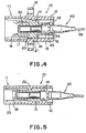
- Fig. 4 is a vertical cross sectional view showing an optical receptacle according to an embodiment of the present invention (I-I cross section in Fig. 6);
- Fig. 5 is a horizontal cross sectional view showing an optical receptacle according to an embodiment of the present invention (II-II cross section in Fig. 6);
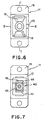
- Fig. 6 is a left side view showing an optical receptacle;
- Fig. 7 is a right side view showing an optical receptacle;
- Fig. 8A is a side cross sectional view showing an inner part of an optical receptacle according to an embodiment of the present invention;
- Fig. 8B is a side cross sectional view showing an outer part of an optical receptacle according to an embodiment of the present invention;
- Fig. 9 is a side view showing the first ferrule of an optical receptacle according to an embodiment of the present invention;
- Fig. 10 is a left end view of the first ferrule of an optical receptacle according to an embodiment of the present invention;
- Fig. 11 is a right end view of the first ferrule of an optical receptacle according to an embodiment of the present invention;
- Fig. 12 is a partial cross sectional view showing an optical fiber connector and inner and outer parts as well as the first ferrule, illustrating the manner of in which the optical receptacle of the present invention is used;
- Fig. 13 is a cross sectional view showing an optical receptacle with a ferrule being inserted therein according to an embodiment of the present invention;
- Fig. 14 is a right end view showing an optical receptacle according to a second embodiment of the present invention;
- Fig. 15 is a side view showing the first ferrule which is connected to an optical receptacle according to a second embodiment of the present invention;
- Fig. 16 is a right end view showing the first ferrule which is connected to an optical receptacle according to a second embodiment of the present invention;
- Fig. 17 is a schematic perspective view showing an eight-element array optical receptacle according to a third embodiment of the'present invention; and
- Fig. 18 is a cross sectional view showing inner and outer parts of an optical receptacle to be assembled, illustrating the step of manufacturing an optical receptacle according to an embodiment of the present invention.
-
- According to the present invention, the housing inlays the inner and outer parts therein to give a fixed structure so that no additional operation such as ultrasonic welding or the like is needed upon assembling the housing. This simplifies assembling operation greatly.
- The inner part can be inserted into the outer part from the side where a terminal or base end of the first ferrule is positioned in the outer part (cf. Figs. 8A and 8B) and inlayed and fixed in the outer part. As a result, even if undesirable tensile force is urged onto the optical fiber cable to which the first ferrule is attached, the inlayed portion of the inner part will not disengage from and come out of the outer part.
- Furthermore, the first ferrule has a flange of an octagonal prism in shape coaxial with the axis of the first ferrule. The octagonal prism continues to a tetragonal prism coaxial with the axis of the first ferrule. The first hooks engage with the octagonal prism, two opposite parallel side surfaces of the octagonal prism are spaced apart from each other at a distance which is larger than the gap between the inner surfaces of the claws of the first hooks. The two opposite parallel side surfaces of the tetragonal prism are spaced apart from each other at a distance is smaller than the gap between the inner surfaces of the claws of the first hooks. Furthermore, The diagonal line has a length equal to or slightly greater than the distance between the parallel side surfaces of the octagonal prism. This construction allows the first ferrule to be released from the engagement with the inner part of the housing simply by being rotated by an angle of 45°. Therefore, the optical receptacle of the present invention can be handled without difficulty.
- The first ferrule held at the base portion of the housing by the first hooks is fitted in a split sleeve while in the optical fiber connector plug connected to the housing at its nose end, the second ferrule is fitted in the split sleeve so that it is aligned and held at the position of fitting by the second hooks. With this simple construction, optical characteristics equivalent to those obtained with the conventional structure can be secured.
- The first hooks for engaging with the first ferrule and the second hooks for engaging with the optical fiber connector plug are molded integrally (i.e., solidly or as one-piece) as an inner part so that the relationship between the positions of the first and second ferrules at the time of coupling can readily be maintained with high precision without high precision assembling operations. As a result, a spring which has been conventionally required to press the first ferrule may be eliminated. Without springs, the first and second ferrules to be connected can firmly be pressed against each other so that the reliability in connecting characteristics can be increased.
- According to the present invention, as shown in Fig. 4, no diaphragm is needed between the
flange 42 of the first ferrule and thesplit sleeve 30. In this case, the split sleeve can reach to the foot of the flange of the first ferrule so that a shorter ferrule can be used, with the result that when ferrules are manufactured less grinding of the outer surfaces of the ferrule is required. Therefore, the optical receptacle can be manufactured at low cost. - Furthermore, when the first ferrule is taken out of the optical receptacle of the present invention, the split sleeve is drawn out simultaneously so that less friction occurs between the first ferrule and the split sleeve. Therefore, inexpensive materials with low friction resistance,such as glass and plastics can be put in practical use for the ferrule.
- Hereinafter, the present invention will be described in greater detail by embodiments with reference to the attached drawings. However, the present invention should not be construed as being limited thereto.
- The optical receptacle according to the first embodiment of the present invention is designed to connect optical transmission components and for this purpose is attached to one of the components. As shown in Figs. 4 and 5, an
optical receptacle 10 includes ahousing 11, asplit sleeve 30 and aferrule 40 to one end of which thesplit sleeve 30 is connected. Thehousing 11 is capable of containing thesplit sleeve 30 and a part of theferrule 40. - The
housing 11 is in form and includes anouter part 12 and aninner part 13 which is inserted into theouter part 12. At a terminal of theinner part 13 is provided afitting portion 14 on whose inner surface aflange 42 of thefirst ferrule 40 fitted (Fig. 5). Above and below thefitting part 14 are arranged a pair offirst hooks 15 having respectivefirst claws 16 on the tips thereof. The first hooks 15 with thefirst claws 16 hold theflange 42 of thefirst ferrule 40 in position (Fig. 4). - On the other hand, on the tip of the
inner part 13 which is opposite to the side where thefirst ferrule 40 is to be fitted, there is provided a pair of second hooks having respective second claws on the tips thereof. Thehooks 17 with therespective claws 18 serve as engaging portions for holding an optical fiber connector 51 (Fig. 12). - On the top of the
outer part 12 is formed akey way 23 for holding theoptical fiber connector 51 having a key 54 and receives the key 54 (Figs. 5 and 6). In the central portion of theouter part 12 is provided afitting flange 19 formed of fitting holes 24 through which screws or the like fitting means are inserted to fix the housing to an optical module (not shown) in position (Figs. 4 and 6). - . On the inner surface of the inner part 13 a
split sleeve 30 is fitted. In thesplit sleeve 30 are fitted on one hand thefirst ferrule 41 which is fitted from the side of the bottom end of theinner part 13, or from right to left in Fig. 4, and on the other hand thesecond ferrule 52 of the opticalfiber connector plug 51 to be connected (Fig. 12). Thus, thesplit sleeve 30 allow the first andsecond ferrules - The
inner part 13 having the above-described structure, which can be molded as an integral component, is inlayed in theouter part 12, which can be also molded as an integral part. Thus, thehousing 11 is constructed. - As shown in Fig. 8A, the
inner part 13 hasfirst protrusions 20 on its upper and lower surfaces while theouter part 12 has on its inner surface asecond protrusion 21 and astep 22. - The
inner part 13 is inserted into theouter part 12 from the side of the base end of thehousing 11 until thefirst protrusions 20 pass by thesecond protrusion 21 against an inward force urged to theinner part 13 by a slightly constricted inner diameter of the cavity. As soon as the first protrusions pass by thesecond protrusion 21, a portion of theinner part 13 abuts thestep 22 provided on the inner surface of theouter part 12 and thus is fixed. - At the
step 22, theinner part 13 and theouter part 12 contact each other along a sufficient are so that theinner part 13 will not come out of theouter part 12 if an excess or otherwise intolerable external force such as a tensile force is urged to theinner part 13. Therefore, there is no danger that the opticalfiber connector plug 51 together with theinner part 13 and thefirst ferrule 40 is drawn out of the optical module to thereby break the device. - The first hooks 15 and
second hooks 17 are molded integrally as theinner part 13. This construction is advantageous in that the relative positions of the first and second hooks can be set with higher precision and assembling operation is more simple as compared with the conventional method in which the both first and second hooks are fabricated separately and subsequently assembled as by ultrasonic welding. - As shown in Figs. 9 to 11, the
flange 42 of thefirst ferrule 40 is configured to a shape of a combination of anoctagonal prism 43 coaxially connected to atetragonal prism 44. As shown in Fig. 4, the distance between two opposing parallel surfaces of thetetragonal prism 44 is made smaller than the distance between thesecond claws 16 themselves. As a result, when thefirst ferrule 40 is engaged with thehousing 11, thehooks 15 are closed, that is, come nearer to each other so that theclaws 16 engage with theoctagonal prism 43 to hold theferrule 40 or prevent rearward movement of theferrule 40 which leads to detachment of theferrule 40. - Referring to Fig. 11, it is assumed that the diagonal line of the
tetragonal prism 44 has a length of L1 while the distance between the parallel two surfaces of the octagonal prism is L2. When the length, L1, of the diagonal line of thetetragonal prism 44 is the same as or slightly larger than the distance, L2, theopposite end points first claws 16 when theferrule 40 is rotated about its longitudinal axis at angles of 45° so that the distance between the opposingfirst claws 16 is made greater than the two parallel surfaces of the octagonal prism. As a result, thefirst ferrule 40 is released and can be readily put out of theinner part 13 of theoptical receptacle 10. In this case, if thefirst ferrule 40 is rotated under the conditions that thesecond ferrule 52 still contacts on its end surface the end surface of thefirst ferrule 40, the end surface of the optical fiber in the ferrule tends to be damaged. Accordingly, when thesecond ferrule 52 is to be taken out of theinner part 13, care must be taken to check to see if the optical fiber connector plug is disconnected from the optical receptacle of the present invention. - Connection of optical transmission components to each other through the
optical receptacle 10 according to the first embodiment of the present invention can be achieved by inserting the opticalfiber connector plug 51 into theoptical receptacle 10 from its left hand side as seen in Fig. 12 so. that theoptical fiber 45 fitted to thefirst ferrule 40 and theoptical fiber cable 53 fitted to thesecond ferrule 52 are aligned. - This embodiment is the second embodiment of the optical receptacle of the present invention.
- Fig. 14 is an right end view showing an optical receptacle according to the second embodiment of the present invention. Fig. 15 is the first ferrule according to the first embodiment of the present invention. Fig. 16 is a right end view showing the first ferrule shown in Fig. 15.
- The optical receptacle according to this embodiment differ from that of the first embodiment of the present invention in the configuration of the flange. The
first ferrule 40 in the present embodiment has aflange 43a which engages with thefirst claws 16 and is of a tetragonal prism instead of the octagonal prism that is used in the first ferrule according to the first embodiment of the present invention as shown in Fig. 9. - With this construction, the ferrule according to this embodiment of the present invention cannot rotate unlike the first ferrule according to the first embodiment of the present invention described above and, hence, the first ferrule with the
tetragonal flange 43a cannot be taken out of thehousing 11 by a mere operation, such as rotation about its longitudinal axis, of thefirst ferrule 40 itself. For releasing thefirst ferrule 40, theflange 43a must be disengaged from thefirst claws 16 of the first hooks 15. This can be achieved by broadening the gap between thefirst claws 16 by a suitable means. In order to broaden the gap between theclaws 16 to release the engagement of theferrule 40 with theinner part 13, a jig in the form of a plate, for example can be inserted in the gap between one of theclaws 16 and thetetragonal prism 44. The jig may be of any desired shape as far as it has two plate-like members such as the plates described above. Alternatively, commonly available tools such as tweezers may also be used for the disengagement of the ferrule from theinner part 13 of the optical receptacle according to this embodiment of the present invention. - With the arrangement according to this embodiment, even if the optical fiber connector is not removed from the optical receptacle by negligence or for some other reasons, the
first ferrule 40 never rotates around its longitudinal axis so that no erroneous or harmful operation can occur such that the end face of the optical fiber is damaged by rotation of thefirst ferrule 40 which contacts the end face of the optical fiber. - FIG. 17 is a schematic perspective view showing an eight-component-array optical receptacle comprising eight receptacles according to the first embodiment of the present invention integrally assembled side by side. The configurations of the first and second ferrules are the same as those of the first and second ferrules in the optical receptacle according to the first or second embodiment of the present invention. The
array housing 70 is an integrally molded article comprising eight single housings integrally combined arranged in parallel side by side. - In this case, the
inner part 13 may be the same as that used in theoptical receptacle 10 according to the first embodiment of the present invention. Accordingly, it is sufficient to change the configuration of only the outer part that is simple in structure and inexpensive. Therefore, the optical receptacle according to this embodiment can be realized at low costs as compared with the case where the entire structure has to be newly produced. - Alternatively, eight-component-array optical receptacle may be realized as a compact article using as an optical fiber connector plug to be connected a high density type SC connector plug 208a having a structure in which the plug is removed with a jig or removing tool after the coupling device is detached from the SC-type optical fiber connector plug.
- This embodiment relates to the manufacture of the housing of the optical receptacle according to any one of EMBODIMENT 1 TO 3 above.
- Fig. 18 is a cross sectional view showing inner and outer parts of an optical receptacle to be assembled, illustrating the step of manufacturing the housing of an optical receptacle according to any one of the foregoing embodiments of the present invention. AS shown in Fig. 18, the
outer part 12 and theinner part 13 which are components of thehousing 11 are separately prepared as integral molded articles, respectively. Then, theinner part 13 is inserted in theouter part 12 until theprotrusions 21 provided in the inner surface of theouter part 12 engage with theprotrusions 20 of theinner part 13 so that theinner part 13 is held fixedly in theouter part 12. The housing thus formed requires no further operation such as ultrasonic welding for bonding these components before it is assembled with the same first ferrule used in the optical receptacle according to any one of the foregoing embodiments. - The present invention has been described in detail with respect to an embodiment, and it will now be apparent from the foregoing to those skilled in the art that changes and modifications may be made without departing from the invention in its broader aspects, and it is the intention, therefore, in the appended claims to cover all such changes and modifications as fall within the true spirit of the invention.
Claims (10)
- An optical receptacle (10) for connecting an optical fiber connector plug (51) attached to an optical fiber (53) provided with a second ferrule (52), characterized by comprising:wherein said inner part comprises :a first ferrule (40) for an optical fiber (45), anda housing (11) having a base end and a nose end, said housing (11) comprising an inner part (13) and an outer part (12) having fixed therein said inner part (13);wherein said sleeve (30) can be drawn out simultaneously when said first ferrule (40) is taken out of the optical receptacle (40).a sleeve (30) for fitting with alignment to said first ferrule (40) and a second ferrule (52),first hook portions (15) holding said first ferrule (40), provided at the base end of said housing (11), andsecond hook portions (17) for holding said optical fiber connector plug (51) at a fitting position of said optical fiber connector plug (51), provided at the nose end of the housing (11), wherein said first and second hook portions (15, 17) are parts of an integral molded article (13)
- The optical receptacle (10) as claimed in claim 1, characterized by further comprising pig-tail optical fiber (45) attached to said first ferrule (40).
- The optical receptacle as claimed in claim 1 or 2, characterized in that said housing (11) comprises a fixing mechanixm (20, 21, 11) which fixes said inner part (13) in position when said inner part (13) is inserted in said outer part (12).
- The optical receptacle as claimed in claim 2 or 3, characterized in that said housing (11) comprises a fixing mechanism (20, 21, 22) which fixes said inner part (13) in position when said inner part (13) is inserted in said outer part (12) from a side where said first ferrule (40) is positioned.
- The optical receptacle (10) as claimed in claim 1, 2, 3 or 4, characterized in that said first ferrule (40) comprises a flange (42) having an octagonal prism portion (43) coaxial with said first ferrule (40) and a tetragonal primsportion (44) coaxial with said first ferrule (40) continuing to said octagonal prism portion (43).
- The optical receptacle as claimed in claim 5, characterized in that said octagonal prism portion (43) engages with said first hook portions (15).
- The optical receptacle as claimed in claim 6, characterized in that said first hook portions (15) have respective claws (16):
wherein said octagonal prism portion (43) has two parallel surfaces arranged along a longitudinal axis of said first ferrule (40) at a distance larger than a gap defined between inner surfaces of the claws (16) of said first hook portions (15);
wherein said tetragonal prism portion (44) has two parallel surfaces at a distance is smaller than the gap between the inner surface of the claws (16) of said first hook portions (15) and a diagonal line of said tetragonal prism portion (44) has a length which is equal to or larger than the distance between the two parallel surfaces of said octagonal prism portion (43). - The optical receptacle as claimed in claim 7, characterized in that the diagonal line of said octagonal prism portion (43) has a length such that said first ferrule (40) is allowed to rotate in said inner part (13) of said housing (11).
- A method for manufacturing an optical receptacle (10) for an optical fiber connector plug (5 1 ), characterized by comprising steps of:wherein said sleeve (30) can be drawn out simultaneously when said first ferrule is taken out of the optical receptacle (40).providing an inner part (13) having first hook portions (15) and a second hook portions (17), as an integral molded article,providing an outer part (12) adapted for fixing said inner part (13) therein,insert said inner part (13) in said outer part (12) to form a housing (11) having a base end and a nose end,providing said inner part (13) with a sleeve (30),fitting a first ferrule (40) for an optical fiber (45) to the base end of said housing (11) in such a way that said first ferrule (40) is fitted in said sleeve (30) and is held by said first hook portions (15).
- The method for manufacturing an optical receptacle as claimed in claim 9, characterized in that said inner part (13) is inserted in said outer part (12) until a fixing mechanism (20, 21, 22) provided in said housing (11) fixes said inner part (13) in position in said outer part (12).
Applications Claiming Priority (3)
| Application Number | Priority Date | Filing Date | Title |
|---|---|---|---|
| JP4806195 | 1995-03-08 | ||
| JP04806195A JP3212063B2 (en) | 1995-03-08 | 1995-03-08 | Optical receptacle |
| EP96200612A EP0731369B1 (en) | 1995-03-08 | 1996-03-06 | Receptacle for optical fibre connection and method of manufacturing the same |
Related Parent Applications (2)
| Application Number | Title | Priority Date | Filing Date |
|---|---|---|---|
| EP96200612.8 Division | 1996-03-06 | ||
| EP96200612A Division EP0731369B1 (en) | 1995-03-08 | 1996-03-06 | Receptacle for optical fibre connection and method of manufacturing the same |
Publications (3)
| Publication Number | Publication Date |
|---|---|
| EP1486808A2 true EP1486808A2 (en) | 2004-12-15 |
| EP1486808A3 EP1486808A3 (en) | 2004-12-29 |
| EP1486808B1 EP1486808B1 (en) | 2012-01-25 |
Family
ID=12792841
Family Applications (2)
| Application Number | Title | Priority Date | Filing Date |
|---|---|---|---|
| EP96200612A Expired - Lifetime EP0731369B1 (en) | 1995-03-08 | 1996-03-06 | Receptacle for optical fibre connection and method of manufacturing the same |
| EP04077203A Expired - Lifetime EP1486808B1 (en) | 1995-03-08 | 1996-03-06 | Receptacle for optical fibre connection and method for its manufacture |
Family Applications Before (1)
| Application Number | Title | Priority Date | Filing Date |
|---|---|---|---|
| EP96200612A Expired - Lifetime EP0731369B1 (en) | 1995-03-08 | 1996-03-06 | Receptacle for optical fibre connection and method of manufacturing the same |
Country Status (3)
| Country | Link |
|---|---|
| US (2) | US5774611A (en) |
| EP (2) | EP0731369B1 (en) |
| JP (1) | JP3212063B2 (en) |
Cited By (8)
| Publication number | Priority date | Publication date | Assignee | Title |
|---|---|---|---|---|
| WO2006022840A1 (en) | 2004-08-24 | 2006-03-02 | Corning Cable Systems Llc | Fiber optic receptacle and plug assemblies with alignment and keying features |
| WO2008116164A3 (en) * | 2007-03-22 | 2009-04-09 | Edwards Lifesciences Corp | Releasably locking auto-aligning fiber optic connector |
| WO2010025180A1 (en) * | 2008-08-27 | 2010-03-04 | Adc Telecommunications, Inc. | Fiber optic adapter with integrally molded ferrule alignment structure |
| CN102789029A (en) * | 2011-05-18 | 2012-11-21 | 深圳市博特光通讯设备有限公司 | Fixing device and fixing method of M-type plastic optical fiber |
| US8317408B2 (en) | 2009-10-05 | 2012-11-27 | Suncall Corporation | Optical-fiber connection unit, and optical connector and optical adapter used therein |
| US9880357B2 (en) | 2013-03-01 | 2018-01-30 | Harting Electric Gmbh & Co. Kg | Optical module for industrial plug-in connectors of modular design |
| US9915793B2 (en) | 2012-09-21 | 2018-03-13 | Commscope Technologies Llc | Removal tool for a fiber optic ferrule alignment sleeve |
| US10302874B2 (en) | 2015-05-15 | 2019-05-28 | Commscope Telecommunications (Shanghai) Co., Ltd. | Alignment sleeve assembly and fiber optic adapter |
Families Citing this family (118)
| Publication number | Priority date | Publication date | Assignee | Title |
|---|---|---|---|---|
| JP3212063B2 (en) * | 1995-03-08 | 2001-09-25 | 日本電信電話株式会社 | Optical receptacle |
| US5815618A (en) * | 1996-06-07 | 1998-09-29 | Molex Incorporated | Adaptor for interconnecting optical fibers |
| JP3066739B2 (en) | 1996-07-15 | 2000-07-17 | セイコーインスツルメンツ株式会社 | General-purpose optical connector and basic plug |
| JP3535952B2 (en) * | 1997-05-08 | 2004-06-07 | 古河電気工業株式会社 | Back panel connector |
| JP3934234B2 (en) * | 1998-01-21 | 2007-06-20 | 富士通株式会社 | Receptacle module |
| US6435730B1 (en) * | 1998-05-06 | 2002-08-20 | The Whitaker Corporation | Optical fiber connector with improved ferrule float feature |
| US7382142B2 (en) | 2000-05-23 | 2008-06-03 | Nanonexus, Inc. | High density interconnect system having rapid fabrication cycle |
| US6812718B1 (en) | 1999-05-27 | 2004-11-02 | Nanonexus, Inc. | Massively parallel interface for electronic circuits |
| US6799976B1 (en) | 1999-07-28 | 2004-10-05 | Nanonexus, Inc. | Construction structures and manufacturing processes for integrated circuit wafer probe card assemblies |
| US6367984B1 (en) * | 1999-11-10 | 2002-04-09 | Lucent Technologies, Inc. | Optical fiber adapter |
| US7952373B2 (en) * | 2000-05-23 | 2011-05-31 | Verigy (Singapore) Pte. Ltd. | Construction structures and manufacturing processes for integrated circuit wafer probe card assemblies |
| EP1292834B1 (en) | 2000-06-20 | 2005-11-30 | Nanonexus, Inc. | Systems for testing integrated circuits |
| US8807843B2 (en) * | 2000-07-17 | 2014-08-19 | Tyco Electronics Corporation | Connector system with physical security feature |
| US9625649B2 (en) * | 2000-07-17 | 2017-04-18 | Commscope Technologies Llc | Connector system with physical security feature |
| JP3786581B2 (en) * | 2001-03-02 | 2006-06-14 | ヒロセ電機株式会社 | Optical connector parts |
| US6609837B2 (en) * | 2001-04-27 | 2003-08-26 | Fitel Usa Corp. | Optical fiber adapter for dissimilar size ferrules |
| US6485189B1 (en) * | 2001-05-09 | 2002-11-26 | Stratos Lightwave, Inc. | High density multiple fiber optic connector |
| US6579014B2 (en) * | 2001-09-28 | 2003-06-17 | Corning Cable Systems Llc | Fiber optic receptacle |
| US6682228B2 (en) | 2002-02-19 | 2004-01-27 | Emcore Corporation | Connector housing for fiber-optic module |
| US6863446B2 (en) | 2002-03-05 | 2005-03-08 | Fci Americas Technology, Inc. | Optical connector adapter with latch inserts |
| AUPS120702A0 (en) * | 2002-03-18 | 2002-04-18 | Kingfisher International Pty. Ltd. | An optical fibre connector system |
| DE10219935A1 (en) | 2002-05-03 | 2003-11-27 | Krone Gmbh | Device for an optical fiber connection |
| US6702477B1 (en) * | 2002-09-23 | 2004-03-09 | Fci Americas Technology, Inc. | Adapter with cap for fiber optic connector |
| US6785460B2 (en) * | 2002-11-27 | 2004-08-31 | Corning Cable Systems Llc | Tool to remove a ferrule from a receptacle |
| GB2397895B (en) * | 2003-01-29 | 2006-05-03 | Agilent Technologies Inc | Opticle fibre connector |
| US6866425B2 (en) * | 2003-02-14 | 2005-03-15 | Adc Telecommunications, Inc. | In-line optical device with removable housing and method |
| US6962445B2 (en) | 2003-09-08 | 2005-11-08 | Adc Telecommunications, Inc. | Ruggedized fiber optic connection |
| DE102004013905B4 (en) | 2004-03-17 | 2006-01-26 | Adc Gmbh | Fiber optic connector |
| DE202004020043U1 (en) * | 2004-12-22 | 2006-02-09 | CCS Technology, Inc., Wilmington | Fiber optic connection device, plug and connector for optical fibers |
| US7416349B2 (en) * | 2005-07-27 | 2008-08-26 | Adc Telecommunications, Inc. | Fiber optic adapter module |
| US7461980B2 (en) * | 2005-09-13 | 2008-12-09 | Avago Technologies Fiber Ip (Singapore) Pte. Ltd. | Transmitter optical sub-assembly receptacle with thicker split sleeve |
| US7568844B2 (en) * | 2006-08-15 | 2009-08-04 | Corning Cable Systems Llc | Ruggedized fiber optic connector assembly |
| US7985027B2 (en) * | 2006-11-14 | 2011-07-26 | Corning Cable Systems Llc | Adapter assembly for coupling dissimilar fiber optic connectors |
| US7572065B2 (en) | 2007-01-24 | 2009-08-11 | Adc Telecommunications, Inc. | Hardened fiber optic connector |
| US7614797B2 (en) * | 2007-01-24 | 2009-11-10 | Adc Telecommunications, Inc. | Fiber optic connector mechanical interface converter |
| US7591595B2 (en) | 2007-01-24 | 2009-09-22 | Adc Telelcommunications, Inc. | Hardened fiber optic adapter |
| US7785016B2 (en) * | 2007-03-12 | 2010-08-31 | Corning Cable Systems Llc | Fiber optic adapter and connector assemblies |
| US7722258B2 (en) * | 2007-05-06 | 2010-05-25 | Adc Telecommunications, Inc. | Interface converter for SC fiber optic connectors |
| US7677814B2 (en) * | 2007-05-06 | 2010-03-16 | Adc Telecommunications, Inc. | Mechanical interface converter for making non-ruggedized fiber optic connectors compatible with a ruggedized fiber optic adapter |
| US7686519B2 (en) * | 2007-06-18 | 2010-03-30 | Adc Telecommunications, Inc. | Hardened fiber optic housing and cable assembly |
| US7942590B2 (en) | 2007-12-11 | 2011-05-17 | Adc Telecommunications, Inc. | Hardened fiber optic connector and cable assembly with multiple configurations |
| JP2009170108A (en) * | 2008-01-10 | 2009-07-30 | Tokai Rika Co Ltd | Dummy connector |
| KR100850925B1 (en) * | 2008-03-14 | 2008-08-07 | 장종호 | Optical adapter with combined optical fiber |
| US7787740B2 (en) * | 2008-06-12 | 2010-08-31 | Corning Cable Systems Llc | Universal cable bracket |
| US8452148B2 (en) | 2008-08-29 | 2013-05-28 | Corning Cable Systems Llc | Independently translatable modules and fiber optic equipment trays in fiber optic equipment |
| US20100322583A1 (en) | 2009-06-19 | 2010-12-23 | Cooke Terry L | High Density and Bandwidth Fiber Optic Apparatuses and Related Equipment and Methods |
| US11294136B2 (en) | 2008-08-29 | 2022-04-05 | Corning Optical Communications LLC | High density and bandwidth fiber optic apparatuses and related equipment and methods |
| US8303193B2 (en) * | 2008-09-30 | 2012-11-06 | Corning Cable Systems Llc | Retention bodies for fiber optic cable assemblies |
| US8285096B2 (en) | 2008-09-30 | 2012-10-09 | Corning Cable Systems Llc | Fiber optic cable assemblies and securing methods |
| US8272792B2 (en) * | 2008-09-30 | 2012-09-25 | Corning Cable Systems Llc | Retention bodies for fiber optic cable assemblies |
| US8417074B2 (en) | 2008-11-21 | 2013-04-09 | Adc Telecommunications, Inc. | Fiber optic telecommunications module |
| ATE534049T1 (en) | 2009-02-24 | 2011-12-15 | Ccs Technology Inc | CABLE HOLDING DEVICE OR ARRANGEMENT FOR USE WITH A CABLE |
| US8699838B2 (en) | 2009-05-14 | 2014-04-15 | Ccs Technology, Inc. | Fiber optic furcation module |
| JP4863319B2 (en) | 2009-05-19 | 2012-01-25 | 日本航空電子工業株式会社 | Optical connector |
| US8280216B2 (en) | 2009-05-21 | 2012-10-02 | Corning Cable Systems Llc | Fiber optic equipment supporting moveable fiber optic equipment tray(s) and module(s), and related equipment and methods |
| US9075216B2 (en) | 2009-05-21 | 2015-07-07 | Corning Cable Systems Llc | Fiber optic housings configured to accommodate fiber optic modules/cassettes and fiber optic panels, and related components and methods |
| EP2443498B1 (en) | 2009-06-19 | 2020-06-24 | Corning Optical Communications LLC | High fiber optic cable packing density apparatus |
| US8712206B2 (en) | 2009-06-19 | 2014-04-29 | Corning Cable Systems Llc | High-density fiber optic modules and module housings and related equipment |
| US8625950B2 (en) | 2009-12-18 | 2014-01-07 | Corning Cable Systems Llc | Rotary locking apparatus for fiber optic equipment trays and related methods |
| JP4925372B2 (en) * | 2009-12-28 | 2012-04-25 | 日本航空電子工業株式会社 | Optical connector adapter |
| JP5411006B2 (en) * | 2010-01-21 | 2014-02-12 | 三和電気工業株式会社 | Simple plug for optical connectors |
| US8593828B2 (en) | 2010-02-04 | 2013-11-26 | Corning Cable Systems Llc | Communications equipment housings, assemblies, and related alignment features and methods |
| CN102870021B (en) | 2010-03-02 | 2015-03-11 | 蒂安电子服务有限责任公司 | Fibre-optic telecommunication module |
| US8913866B2 (en) | 2010-03-26 | 2014-12-16 | Corning Cable Systems Llc | Movable adapter panel |
| CA2796221C (en) | 2010-04-16 | 2018-02-13 | Ccs Technology, Inc. | Sealing and strain relief device for data cables |
| EP2381284B1 (en) | 2010-04-23 | 2014-12-31 | CCS Technology Inc. | Under floor fiber optic distribution device |
| US9632270B2 (en) | 2010-04-30 | 2017-04-25 | Corning Optical Communications LLC | Fiber optic housings configured for tool-less assembly, and related components and methods |
| US9075217B2 (en) | 2010-04-30 | 2015-07-07 | Corning Cable Systems Llc | Apparatuses and related components and methods for expanding capacity of fiber optic housings |
| US9720195B2 (en) | 2010-04-30 | 2017-08-01 | Corning Optical Communications LLC | Apparatuses and related components and methods for attachment and release of fiber optic housings to and from an equipment rack |
| US8705926B2 (en) | 2010-04-30 | 2014-04-22 | Corning Optical Communications LLC | Fiber optic housings having a removable top, and related components and methods |
| US8879881B2 (en) | 2010-04-30 | 2014-11-04 | Corning Cable Systems Llc | Rotatable routing guide and assembly |
| US8660397B2 (en) | 2010-04-30 | 2014-02-25 | Corning Cable Systems Llc | Multi-layer module |
| US9519118B2 (en) | 2010-04-30 | 2016-12-13 | Corning Optical Communications LLC | Removable fiber management sections for fiber optic housings, and related components and methods |
| WO2011163266A2 (en) * | 2010-06-21 | 2011-12-29 | Finisar Corporation | Fiber optic connectors |
| US8718436B2 (en) | 2010-08-30 | 2014-05-06 | Corning Cable Systems Llc | Methods, apparatuses for providing secure fiber optic connections |
| US9279951B2 (en) | 2010-10-27 | 2016-03-08 | Corning Cable Systems Llc | Fiber optic module for limited space applications having a partially sealed module sub-assembly |
| US8662760B2 (en) | 2010-10-29 | 2014-03-04 | Corning Cable Systems Llc | Fiber optic connector employing optical fiber guide member |
| EP2646867B1 (en) | 2010-11-30 | 2018-02-21 | Corning Optical Communications LLC | Fiber device holder and strain relief device |
| CN102565957B (en) * | 2010-12-31 | 2014-03-26 | 深圳日海通讯技术股份有限公司 | Optical fiber connector |
| WO2012106513A1 (en) | 2011-02-02 | 2012-08-09 | Corning Cable Systems Llc | Dense shuttered fiber optic connectors and assemblies suitable for establishing optical connections for optical backplanes in equipment racks |
| US9008485B2 (en) | 2011-05-09 | 2015-04-14 | Corning Cable Systems Llc | Attachment mechanisms employed to attach a rear housing section to a fiber optic housing, and related assemblies and methods |
| JP5627009B2 (en) * | 2011-06-13 | 2014-11-19 | 日本電信電話株式会社 | Optical connector provided with plug and adapter, and method of connecting optical connector |
| WO2013003303A1 (en) | 2011-06-30 | 2013-01-03 | Corning Cable Systems Llc | Fiber optic equipment assemblies employing non-u-width-sized housings and related methods |
| US8953924B2 (en) | 2011-09-02 | 2015-02-10 | Corning Cable Systems Llc | Removable strain relief brackets for securing fiber optic cables and/or optical fibers to fiber optic equipment, and related assemblies and methods |
| US9417418B2 (en) | 2011-09-12 | 2016-08-16 | Commscope Technologies Llc | Flexible lensed optical interconnect device for signal distribution |
| CN108594384B (en) | 2011-10-07 | 2022-03-08 | Adc电信公司 | Fiber optic cassettes, systems and methods |
| US9038832B2 (en) | 2011-11-30 | 2015-05-26 | Corning Cable Systems Llc | Adapter panel support assembly |
| US9250409B2 (en) | 2012-07-02 | 2016-02-02 | Corning Cable Systems Llc | Fiber-optic-module trays and drawers for fiber-optic equipment |
| US9081152B2 (en) | 2012-08-30 | 2015-07-14 | Adc Telecommunications, Inc. | Adapter pack with removable sleeves |
| US9042702B2 (en) | 2012-09-18 | 2015-05-26 | Corning Cable Systems Llc | Platforms and systems for fiber optic cable attachment |
| US9146374B2 (en) | 2012-09-28 | 2015-09-29 | Adc Telecommunications, Inc. | Rapid deployment packaging for optical fiber |
| NZ706687A (en) | 2012-09-28 | 2017-09-29 | Adc Telecommunications Inc | Fiber optic cassette |
| US9223094B2 (en) | 2012-10-05 | 2015-12-29 | Tyco Electronics Nederland Bv | Flexible optical circuit, cassettes, and methods |
| ES2551077T3 (en) | 2012-10-26 | 2015-11-16 | Ccs Technology, Inc. | Fiber optic management unit and fiber optic distribution device |
| US9268100B2 (en) * | 2012-11-12 | 2016-02-23 | Commscope, Inc. Of North Carolina | Fiber optic connector adapter |
| US9069141B2 (en) * | 2012-12-10 | 2015-06-30 | Baker Hughes Incorporated | Fiber optic termination arrangement and method of making the same |
| US8985862B2 (en) | 2013-02-28 | 2015-03-24 | Corning Cable Systems Llc | High-density multi-fiber adapter housings |
| US9435975B2 (en) | 2013-03-15 | 2016-09-06 | Commscope Technologies Llc | Modular high density telecommunications frame and chassis system |
| ES2700963T3 (en) | 2013-06-27 | 2019-02-20 | CommScope Connectivity Belgium BVBA | Anchoring device for fiber optic cable for use with fiber optic connectors and methods of using it |
| CN104777560B (en) * | 2014-01-14 | 2017-09-26 | 华为技术有限公司 | The joints of optical fibre and fiber optic connector assembly system |
| WO2015116672A1 (en) | 2014-01-28 | 2015-08-06 | Adc Telecommunications, Inc. | Slidable fiber optic connection module with cable slack management |
| US9494758B2 (en) | 2014-04-03 | 2016-11-15 | Commscope Technologies Llc | Fiber optic distribution system |
| US9551598B2 (en) | 2014-05-12 | 2017-01-24 | Siemens Energy, Inc. | Fiber optic sensing apparatus with an improved fiber-affixing device |
| JP6318008B2 (en) * | 2014-05-30 | 2018-04-25 | 株式会社フジクラ | Optical connector |
| FR3024244B1 (en) * | 2014-07-25 | 2018-01-05 | Bbright | DIODE COUPLING MODULE LASERS |
| JP2016109816A (en) * | 2014-12-04 | 2016-06-20 | 株式会社フジクラ | Optical connector fixing member, optical connector and optical connector device |
| CN205374820U (en) * | 2016-02-01 | 2016-07-06 | 上海光联通讯技术有限公司 | Optical fiber adapter |
| US10725248B2 (en) * | 2017-01-30 | 2020-07-28 | Senko Advanced Components, Inc. | Fiber optic receptacle with integrated device therein incorporating a behind-the-wall fiber optic receptacle |
| US10871619B2 (en) * | 2017-01-30 | 2020-12-22 | Senko Advanced Components, Inc. | Cassette assembly for a plural of fiber optic receptacles |
| CN206479676U (en) * | 2017-02-16 | 2017-09-08 | 光联通讯有限公司 | Fiber-optical socket, optical fiber splicing device and fiber-optical socket module |
| JP7115739B2 (en) * | 2017-08-09 | 2022-08-09 | 株式会社精工技研 | optical connector adapter |
| CN111164479B (en) | 2017-10-02 | 2021-11-19 | 康普技术有限责任公司 | Fiber optic circuits and methods of making |
| JP7079924B2 (en) * | 2017-10-30 | 2022-06-03 | アダマンド並木精密宝石株式会社 | Optical receptacle |
| TW201928429A (en) * | 2017-12-27 | 2019-07-16 | 和碩聯合科技股份有限公司 | Optical fiber connector |
| CN114600018B (en) * | 2019-07-23 | 2024-04-09 | 扇港元器件有限公司 | Ultra-small receptacle for receiving a fiber optic connector opposite a ferrule assembly |
| TWI722902B (en) * | 2020-02-26 | 2021-03-21 | 立佳興業股份有限公司 | Latching structure and optical connector receptacle using the same |
| TWI781413B (en) * | 2020-02-26 | 2022-10-21 | 立佳興業股份有限公司 | Latching structure and optical connector receptacle using the same |
| CN113625397B (en) * | 2021-06-29 | 2023-07-21 | 武汉联特科技股份有限公司 | Detachable optical fiber adapter and optical device |
Citations (4)
| Publication number | Priority date | Publication date | Assignee | Title |
|---|---|---|---|---|
| JPH03130706A (en) * | 1989-10-16 | 1991-06-04 | Fujitsu Ltd | Optical module |
| WO1994012901A1 (en) * | 1992-11-30 | 1994-06-09 | Bt&D Technologies Ltd. | Optical connector |
| WO1994024594A1 (en) * | 1993-04-08 | 1994-10-27 | The Whitaker Corporation | Optical fibre connector latching mechanism |
| US5373574A (en) * | 1992-05-20 | 1994-12-13 | Diamond Sa | Connector for an optical fiber |
Family Cites Families (8)
| Publication number | Priority date | Publication date | Assignee | Title |
|---|---|---|---|---|
| DE7612933U1 (en) * | 1976-04-24 | 1976-09-09 | Cannon Electric Gmbh, 7056 Beutelsbach | COUPLING HOUSING FOR LIGHT GUIDE CABLE |
| JPS5689709A (en) * | 1979-12-21 | 1981-07-21 | Nec Corp | Plastic plug for optical fiber and connector using it |
| US4415232A (en) * | 1981-03-16 | 1983-11-15 | Amp Incorporated | Optical waveguide splice |
| US4477146A (en) * | 1981-03-16 | 1984-10-16 | Amp Incorporated | Optical waveguide connector |
| US4418983A (en) * | 1981-03-16 | 1983-12-06 | Amp Incorporated | Optical waveguide connector |
| JP3212063B2 (en) * | 1995-03-08 | 2001-09-25 | 日本電信電話株式会社 | Optical receptacle |
| US5748818A (en) * | 1995-12-22 | 1998-05-05 | Weiss; Roger E. | Massive parallel optical interconnect system |
| US5737463A (en) * | 1995-12-22 | 1998-04-07 | Weiss; Roger E. | Massive parallel optical interconnect system |
-
1995
- 1995-03-08 JP JP04806195A patent/JP3212063B2/en not_active Expired - Lifetime
-
1996
- 1996-03-06 EP EP96200612A patent/EP0731369B1/en not_active Expired - Lifetime
- 1996-03-06 US US08/611,779 patent/US5774611A/en not_active Expired - Lifetime
- 1996-03-06 EP EP04077203A patent/EP1486808B1/en not_active Expired - Lifetime
-
1998
- 1998-03-26 US US09/048,778 patent/US5887095A/en not_active Expired - Lifetime
Patent Citations (4)
| Publication number | Priority date | Publication date | Assignee | Title |
|---|---|---|---|---|
| JPH03130706A (en) * | 1989-10-16 | 1991-06-04 | Fujitsu Ltd | Optical module |
| US5373574A (en) * | 1992-05-20 | 1994-12-13 | Diamond Sa | Connector for an optical fiber |
| WO1994012901A1 (en) * | 1992-11-30 | 1994-06-09 | Bt&D Technologies Ltd. | Optical connector |
| WO1994024594A1 (en) * | 1993-04-08 | 1994-10-27 | The Whitaker Corporation | Optical fibre connector latching mechanism |
Non-Patent Citations (2)
| Title |
|---|
| KANAYAMA K ET AL: "CHARACTERISTICS AND STATIC FATIGUE RELIABILITY OF A ZIRCONIA ALIGNMENT SLEEVE FOR OPTICAL CONNECTORS" IEICE TRANSACTIONS ON ELECTRONICS, INSTITUTE OF ELECTRONICS INFORMATION AND COMM. ENG. TOKYO, JP, vol. E77-C, no. 10, 1 October 1994 (1994-10-01), pages 1559-1566, XP000496089 ISSN: 0916-8524 * |
| PATENT ABSTRACTS OF JAPAN vol. 0153, no. 44 (P-1245), 30 August 1991 (1991-08-30) & JP 3 130706 A (FUJITSU LTD), 4 June 1991 (1991-06-04) * |
Cited By (24)
| Publication number | Priority date | Publication date | Assignee | Title |
|---|---|---|---|---|
| AU2005278173B2 (en) * | 2004-08-24 | 2011-08-25 | Corning Cable Systems Llc | Fiber optic receptacle and plug assemblies with alignment and keying features |
| WO2006022840A1 (en) | 2004-08-24 | 2006-03-02 | Corning Cable Systems Llc | Fiber optic receptacle and plug assemblies with alignment and keying features |
| EP1782114B1 (en) * | 2004-08-24 | 2010-08-04 | Corning Cable Systems LLC | Fiber optic receptacle and plug assemblies with alignment and keying features |
| WO2008116164A3 (en) * | 2007-03-22 | 2009-04-09 | Edwards Lifesciences Corp | Releasably locking auto-aligning fiber optic connector |
| US7654849B2 (en) | 2007-03-22 | 2010-02-02 | Edwards Lifesciences Corporation | Releasably locking auto-aligning fiber optic connector |
| US7901235B2 (en) | 2007-03-22 | 2011-03-08 | Edwards Lifesciences Corporation | Releasably locking auto-aligning fiber optic connector |
| US8992095B2 (en) | 2008-08-27 | 2015-03-31 | Adc Telecommunications, Inc. | Fiber optic adapter with integrally molded ferrule alignment structure |
| US9354402B2 (en) | 2008-08-27 | 2016-05-31 | Commscope Technologies Llc | Fiber optic adapter with integrally molded ferrule alignment structure |
| US10795090B2 (en) | 2008-08-27 | 2020-10-06 | Commscope Technologies Llc | Fiber optic adapter with integrally molded ferrule alignment structure |
| US8382382B2 (en) | 2008-08-27 | 2013-02-26 | Adc Telecommunications, Inc. | Fiber optic adapter with integrally molded ferrule alignment structure |
| CN102132182B (en) * | 2008-08-27 | 2013-10-02 | Adc电信公司 | Fiber optic adapter with integrally molded ferrule alignment structure |
| US8845205B2 (en) | 2008-08-27 | 2014-09-30 | Adc Telecommunications, Inc. | Fiber optic adapter with integrally molded ferrule alignment structure |
| WO2010025180A1 (en) * | 2008-08-27 | 2010-03-04 | Adc Telecommunications, Inc. | Fiber optic adapter with integrally molded ferrule alignment structure |
| US11262507B2 (en) | 2008-08-27 | 2022-03-01 | Commscope Technologies Llc | Fiber optic adapter with integrally molded ferrule alignment structure |
| US9778422B2 (en) | 2008-08-27 | 2017-10-03 | Commscope Technologies Llc | Fiber optic adapter with integrally molded ferrule alignment structure |
| US11567267B2 (en) | 2008-08-27 | 2023-01-31 | Commscope Technologies Llc | Fiber optic adapter with integrally molded ferrule alignment structure |
| US10197741B2 (en) | 2008-08-27 | 2019-02-05 | Commscope Technologies Llc | Fiber optic adapter with integrally molded ferrule alignment structure |
| US12001061B2 (en) | 2008-08-27 | 2024-06-04 | Commscope Technologies Llc | Fiber optic adapter with integrally molded ferrule alignment structure |
| US8317408B2 (en) | 2009-10-05 | 2012-11-27 | Suncall Corporation | Optical-fiber connection unit, and optical connector and optical adapter used therein |
| CN102789029A (en) * | 2011-05-18 | 2012-11-21 | 深圳市博特光通讯设备有限公司 | Fixing device and fixing method of M-type plastic optical fiber |
| US9915793B2 (en) | 2012-09-21 | 2018-03-13 | Commscope Technologies Llc | Removal tool for a fiber optic ferrule alignment sleeve |
| US9880357B2 (en) | 2013-03-01 | 2018-01-30 | Harting Electric Gmbh & Co. Kg | Optical module for industrial plug-in connectors of modular design |
| RU2653561C2 (en) * | 2013-03-01 | 2018-05-11 | Хартинг Электрик Гмбх Унд Ко. Кг | Optical module for industrial plug-in connectors of modular design |
| US10302874B2 (en) | 2015-05-15 | 2019-05-28 | Commscope Telecommunications (Shanghai) Co., Ltd. | Alignment sleeve assembly and fiber optic adapter |
Also Published As
| Publication number | Publication date |
|---|---|
| US5774611A (en) | 1998-06-30 |
| EP1486808A3 (en) | 2004-12-29 |
| US5887095A (en) | 1999-03-23 |
| JPH08248263A (en) | 1996-09-27 |
| EP0731369A3 (en) | 1997-03-05 |
| EP1486808B1 (en) | 2012-01-25 |
| EP0731369B1 (en) | 2004-11-17 |
| JP3212063B2 (en) | 2001-09-25 |
| EP0731369A2 (en) | 1996-09-11 |
Similar Documents
| Publication | Publication Date | Title |
|---|---|---|
| US5774611A (en) | Optical receptacle and housing therefor | |
| US12013578B2 (en) | Multifiber fiber optic connectors, cable assemblies and methods of making the same | |
| US11573386B2 (en) | Fiber optic connector assembly, apparatus for forming a transceiver interface, and ferrule | |
| US5666449A (en) | Optical waveguide device | |
| EP2548062B1 (en) | Fiber optic interface devices for electronic devices | |
| CA2199711C (en) | Optical connector plug and optical connector | |
| AU708527B2 (en) | Jack receptacle for an optical connector | |
| US6454464B1 (en) | Fiber optic connectors and transceiver test devices | |
| CA2751329C (en) | Fiber optic jack and connector | |
| US5577146A (en) | Optical connectors | |
| US5727102A (en) | Multifiber optical connector for optical ribbon cable | |
| US10025038B2 (en) | Optical adaptor for mounting to a receptacle to optically couple connectorized optical cables | |
| EP1193516A2 (en) | Adapter for coupling used with fiber optic connectors | |
| US20040247250A1 (en) | Integrated sleeve pluggable package | |
| WO2021216179A1 (en) | Connector assemblies for hybrid fiber/wire connections | |
| JPH01248111A (en) | Optical receptacle | |
| JPH0894880A (en) | Optical receptacle |
Legal Events
| Date | Code | Title | Description |
|---|---|---|---|
| PUAI | Public reference made under article 153(3) epc to a published international application that has entered the european phase |
Free format text: ORIGINAL CODE: 0009012 |
|
| PUAL | Search report despatched |
Free format text: ORIGINAL CODE: 0009013 |
|
| AC | Divisional application: reference to earlier application |
Ref document number: 0731369 Country of ref document: EP Kind code of ref document: P |
|
| AK | Designated contracting states |
Kind code of ref document: A2 Designated state(s): IT SE |
|
| AK | Designated contracting states |
Kind code of ref document: A3 Designated state(s): IT SE |
|
| RIN1 | Information on inventor provided before grant (corrected) |
Inventor name: NAGASE, RYO Inventor name: IWANO, SHIN-ICHI |
|
| 17P | Request for examination filed |
Effective date: 20050614 |
|
| RTI1 | Title (correction) |
Free format text: RECEPTACLE FOR OPTICAL FIBRE CONNECTION AND METHOD FOR ITS MANUFACTURE |
|
| AKX | Designation fees paid |
Designated state(s): IT SE |
|
| GRAP | Despatch of communication of intention to grant a patent |
Free format text: ORIGINAL CODE: EPIDOSNIGR1 |
|
| GRAS | Grant fee paid |
Free format text: ORIGINAL CODE: EPIDOSNIGR3 |
|
| GRAA | (expected) grant |
Free format text: ORIGINAL CODE: 0009210 |
|
| AC | Divisional application: reference to earlier application |
Ref document number: 0731369 Country of ref document: EP Kind code of ref document: P |
|
| AK | Designated contracting states |
Kind code of ref document: B1 Designated state(s): IT SE |
|
| REG | Reference to a national code |
Ref country code: SE Ref legal event code: TRGR |
|
| PLBE | No opposition filed within time limit |
Free format text: ORIGINAL CODE: 0009261 |
|
| STAA | Information on the status of an ep patent application or granted ep patent |
Free format text: STATUS: NO OPPOSITION FILED WITHIN TIME LIMIT |
|
| 26N | No opposition filed |
Effective date: 20121026 |
|
| PGFP | Annual fee paid to national office [announced via postgrant information from national office to epo] |
Ref country code: SE Payment date: 20140327 Year of fee payment: 19 |
|
| PGFP | Annual fee paid to national office [announced via postgrant information from national office to epo] |
Ref country code: IT Payment date: 20140327 Year of fee payment: 19 |
|
| PG25 | Lapsed in a contracting state [announced via postgrant information from national office to epo] |
Ref country code: SE Free format text: LAPSE BECAUSE OF NON-PAYMENT OF DUE FEES Effective date: 20150307 |
|
| REG | Reference to a national code |
Ref country code: SE Ref legal event code: EUG |
|
| PG25 | Lapsed in a contracting state [announced via postgrant information from national office to epo] |
Ref country code: IT Free format text: LAPSE BECAUSE OF NON-PAYMENT OF DUE FEES Effective date: 20150306 |