EP1486804A1 - Polarization preserving optical fiber - Google Patents
Polarization preserving optical fiber Download PDFInfo
- Publication number
- EP1486804A1 EP1486804A1 EP03712678A EP03712678A EP1486804A1 EP 1486804 A1 EP1486804 A1 EP 1486804A1 EP 03712678 A EP03712678 A EP 03712678A EP 03712678 A EP03712678 A EP 03712678A EP 1486804 A1 EP1486804 A1 EP 1486804A1
- Authority
- EP
- European Patent Office
- Prior art keywords
- polarization
- optical fiber
- stress
- maintaining optical
- diameter
- Prior art date
- Legal status (The legal status is an assumption and is not a legal conclusion. Google has not performed a legal analysis and makes no representation as to the accuracy of the status listed.)
- Granted
Links
Images


Classifications
-
- G—PHYSICS
- G02—OPTICS
- G02B—OPTICAL ELEMENTS, SYSTEMS OR APPARATUS
- G02B6/00—Light guides; Structural details of arrangements comprising light guides and other optical elements, e.g. couplings
- G02B6/02—Optical fibres with cladding with or without a coating
- G02B6/024—Optical fibres with cladding with or without a coating with polarisation maintaining properties
-
- G—PHYSICS
- G02—OPTICS
- G02B—OPTICAL ELEMENTS, SYSTEMS OR APPARATUS
- G02B6/00—Light guides; Structural details of arrangements comprising light guides and other optical elements, e.g. couplings
- G02B6/10—Light guides; Structural details of arrangements comprising light guides and other optical elements, e.g. couplings of the optical waveguide type
- G02B6/105—Light guides; Structural details of arrangements comprising light guides and other optical elements, e.g. couplings of the optical waveguide type having optical polarisation effects
Definitions
- the present invention relates a polarization-maintaining optical fiber which includes a small-diameter cladding of about 80 ⁇ m. More specifically, the present invention relates to an optical fiber which exhibits lower splice loss compared to a conventional polarization-maintaining optical fiber having a cladding 125 ⁇ m in diameter.
- Polarization-maintaining optical fibers have been conventionally employed as optical fibers for coupling optical components which exhibit polarization dependence.
- such fibers are assembled into optical transmission components, e.g., fiber gratings and optical fiber couplers, for use in various optical transmission or measurement devices such as optical fiber gyroscopes.
- polarization-maintaining optical fibers which are formed by providing stress-applying parts within a cladding at opposing sides with respect to a core to impart birefringence to the core are well known, as disclosed in United States Patent No. 4,478,489 and Japanese Patent No. 2,750,345, for example.
- a polarization-maintaining optical fiber having such a structure are called a PANDA polarization-maintaining optical fiber (Polarization-maintaining AND Absorption-reducing optical fiber, hereinafter referred to as a "PANDA fiber"), and one of the advantageous characteristics of PANDA fibers are that PANDA fibers having an excellent polarization-maintaining performance can be manufactured with high precision.
- PANDA fiber Polarization-maintaining AND Absorption-reducing optical fiber
- Polarization-maintaining optical fibers having a cladding 125 ⁇ m in diameter are commonly used since such fibers are easy to manufacture, can be manufactured with a uniform quality, and easily couple to conventional optical fibers used for transmission.
- a proof test has been conventionally conducted where predetermined tension is applied to fibers to be tested and broken ones are removed.
- polarization-maintaining optical fiber which can be bent with a bending radius smaller than 20 mm
- a polarization-maintaining optical fiber having a small-diameter cladding of 80 ⁇ m used for gyroscope is known, as reported in "Polarization-maintaining Optical Fiber", Fujikura Technical Review, No. 85, October 1993.
- this polarization-maintaining optical fiber for gyroscope is designed so that the fiber has a larger relative refractive index difference ⁇ between the core and the cladding (e.g., 0.8-1.2%) (hereinafter just referred to as "relative refractive index difference"), and has a smaller mode field diameter (MFD) (e.g., between 3 ⁇ m and 5 ⁇ m at a wavelength of 0.85 ⁇ m, and between 5.5 ⁇ m and 7.5 ⁇ m at 1.55 ⁇ m) than conventional polarization-maintaining optical fibers.
- MFD mode field diameter
- a smaller mode field diameter is disadvantageous since splice loss due to an axial offset incurred during fusion splicing tends to increase.
- a fiber having a smaller mode field diameter is spliced with a telecommunication optical fiber having a cladding 125 ⁇ m in diameter, e.g., an optical fiber for transmission, splice loss due to a difference in mode field diameters becomes significant.
- polarization-maintaining optical fiber for gyroscopes can be manufactured based on the aforementioned structural parameters because such fibers are not to be coupled with another optical fiber, splice loss is a critical issue in a polarization-maintaining optical fiber used for coupling or other applications. Therefore, structural parameters of polarization-maintaining optical fibers for gyroscope cannot be used for polarization-maintaining optical fibers used for coupling or other applications.
- the present invention was made in view of the above-mentioned background, and an object thereof is to provide a polarization-maintaining optical fiber which has a small-diameter cladding of about 80 ⁇ m while exhibiting an excellent polarization-maintaining performance and a reduced splice loss when spliced with a polarization-maintaining optical fiber having a cladding 125 ⁇ m in diameter.
- a polarization-maintaining optical fiber including a core, a pair of stress-applying parts provided radially outwardly with respect to the core, and a cladding which surrounds the core and the stress-applying parts, wherein a diameter of the cladding is between 70 ⁇ m and 90 ⁇ m, a diameter of the stress-applying parts is between 21 ⁇ m and 32 ⁇ m, a distance between the stress-applying parts is between 6 ⁇ m and 17 ⁇ m, and a relative refractive index difference between the core and the cladding is between 0.3% and 0.5%.
- the diameter of the stress-applying parts is between 22 ⁇ m and 28 ⁇ m, the distance between the stress-applying parts is between 8.5 ⁇ m and 11 ⁇ m, and a modal birefringence is 3 ⁇ 10 -4 or higher, and a mode field diameter at a wavelength of 0.98 ⁇ m is between 5.3 ⁇ m and 6.5 ⁇ m for obtaining excellent performance.
- the diameter of the stress-applying parts is between 22 ⁇ m and 28 ⁇ m, the distance between the stress-applying parts is between 9 ⁇ m and 13 ⁇ m, and the modal birefringence is 3 ⁇ 10 -4 or higher, and the mode field diameter at a wavelength of 1.30 ⁇ m is between 7.1 ⁇ m and 9.0 ⁇ m.
- a polarization-maintaining optical fiber is used for a 1.40-1.63 ⁇ m band
- the diameter of the stress-applying parts is between 22 ⁇ m and 28 ⁇ m
- the distance between the stress-applying parts is between 13 ⁇ m and 16 ⁇ m
- the modal birefringence is 3 ⁇ 10 -4 or higher
- the mode field diameter at a wavelength 1.55 ⁇ m is between 8.5 ⁇ m and 10.5 ⁇ m.
- the aforementioned polarization-maintaining optical fiber is suitable as a polarization-maintaining optical fiber used in an optical fiber amplifier, a semiconductor laser, and a modulator; thus smaller optical fiber amplifiers, semiconductor lasers and modulators can be fabricated.
- FIG. 1 is a schematic cross-sectional view exemplifying a polarization-maintaining optical fiber according to the present invention. Similar to a conventional PANDA polarization-maintaining optical fiber, the polarization-maintaining optical fiber according to the present invention is designed such that a pair of the stress-applying parts 2 are provided symmetrically opposing positions with respect to a core 1, and the core 1 and the stress-applying parts 2 are surrounded by a cladding 3, as shown in FIG. 1.
- the core 1 is made of a material which has a higher refractive index than the material of the cladding 3, and the stress-applying part 2 is made of a material which has a higher thermal expansion coefficient than the materials of the core 1 and the cladding 3.
- the core 1 is made of silica which contains (is doped with) germanium
- each of the stress-applying parts 2 are made of B 2 O 3 -SiO 2 glass in which glass is doped with B 2 O 3 such that boron concentration is between 17 wt-% and 21 wt-% in terms of weight concentration of B 2 O 3
- the cladding 3 is made of pure silica.
- the cladding diameter may be between 70 ⁇ m and 90 ⁇ m, and is more preferably between 77 ⁇ m and 83 ⁇ m.
- the diameter D of each of the stress-applying parts 2 may be between 21 ⁇ m and 32 ⁇ m, the distance R between the stress-applying parts 2 may be between 6 ⁇ m and 17 ⁇ m, relative refractive index difference ⁇ may be between 0.3% and 0.5%.
- a cladding has a small diameter, a bending radius of the optical fiber can be reduced to an order of 13 mm.
- polarization crosstalk is reduced, an excellent polarization-maintaining performance is realized, and splice loss is low when spliced with a typical telecommunication optical fiber having a cladding 125 ⁇ m in diameter.
- the diameter of respective stress-applying parts 2 may be between 22 ⁇ m and 28 ⁇ m, the distance between the stress-applying parts 2 may be between 8.5 ⁇ m and 11 ⁇ m, and modal birefringence may be 3 ⁇ 10 -4 or higher, and the mode field diameter at a wavelength of 0.98 ⁇ m may be between 5.3 ⁇ m and 6.5 ⁇ m for obtaining excellent performance.
- the diameter of respective stress-applying parts 2 may be between 22 ⁇ m and 28 ⁇ m, the distance between the stress-applying parts 2 may be between 9 ⁇ m and 13 ⁇ m, and modal birefringence may be 3 ⁇ 10 -4 or higher, and the mode field diameter at a wavelength of 1.30 ⁇ m may be between 7.1 ⁇ m and 9.0 ⁇ m.
- the diameter of respective stress-applying parts 2 may be between 22 ⁇ m and 28 ⁇ m, a distance between the stress-applying parts 2 may be between 13 ⁇ m and 16 ⁇ m, modal birefringence may be 3 ⁇ 10 -4 or higher, and the mode field diameter at a wavelength 1.55 ⁇ m may be between 8.5 ⁇ m and 10.5 ⁇ m.
- polarization-maintaining performance of a polarization-maintaining optical fiber is dependent on modal birefringence B which is defined as the difference between equivalent refractive indices n x , n y (n x -n y ) of two polarized wave modes of the polarization-maintaining optical fiber (x and y polarized waves) which are orthogonal to each other.
- modal birefringence B increases, the difference between propagation constants of two polarized wave modes increases; thus polarization-maintaining performance of this polarization-maintaining optical fiber is improved.
- the modal birefringence B of the PANDA polarization-maintaining optical fiber as shown in FIG. 1 can be expressed by the following Formula (1) (P. L. Chu et. al, "Analytical Method for Calculation of Stress and Material Birefringence in Polarization-Maintaining Optical Fiber", J. of Lightwave Technol. Vol. LT-2, No.5, Oct.
- B modal birefringence
- E Young's modulus of silica
- C photoelastic coefficient
- ⁇ Poisson's ratio
- ⁇ 2 thermal expansion coefficient of the cladding 3
- ⁇ 3 thermal expansion coefficient of the stress-applying parts 2
- T is the difference between the melting point and an actual operating temperature of the stress-applying parts 2
- d 1 is the radius of the stress-applying parts 2
- d 2 is the distance between the center of the core 1 and the center of the stress-applying part 2
- b is the radius of the cladding 3.
- r and 9 present a coordinate of a given point within the polarization-maintaining optical fiber with respect to the origin, i.e., the center of the core 1.
- Formula (1) represents the central value of modal birefringence of the polarization-maintaining optical fiber.
- the stress-applying part 2 is generally made of B 2 O 3 -doped silica, and the amount of boron is preferably 21 wt-% or less in terms of weight concentration of B 2 O 3 (see, e.g., Japanese Unexamined Patent No. 2002-214465).
- a typical material of the stress-applying parts 2 can be expressed using the following empirically known values: E of 7830 kg/mm 2 , ⁇ of 0.186, and ( ⁇ 2 - ⁇ 3 )T of 1.69 ⁇ 10 -3 .
- the term expressed by the following Formula (3): is determined by structural parameters of the polarization-maintaining optical fiber, and it is evident that a larger modal birefringence B can be obtained by increasing diameter D of the stress-applying parts 2 and reducing the distance R between the stress-applying parts 2.
- a relationship of the diameter D of the stress-applying parts 2 versus the distance R between the stress-applying parts 2 were calculated using Formula (1) for a polarization-maintaining optical fiber having a cladding 80 ⁇ m in diameter, assuming that the modal birefringence B is a constant. The results are shown in FIG. 2.
- FIG. 2 indicates that a large modal birefringence B can be achieved by reducing the distance R between the stress-applying parts 2.
- the distance R between the stress-applying parts 2 cannot be smaller than the diameter of the core 1, as shown in FIG. 1.
- mode field diameter is a diameter of an area where the electric field intensity caused by propagation of light becomes 1/e times (e is the base of natural logarithm) the electric field intensity at the center of the core 1.
- the mode field 4 may become deformed from a circulatory shape because the stress-applying parts 2 has a lower refractive index than the cladding 3; thus splice loss is increased.
- non-circularity of the mode field 4 is preferably 3.2% or less, as described in Japanese Patent Application No. 2001-210648.
- maximizing the distance R between the stress-applying parts 2 is desirable, and the results shown in FIG. 2 indicate that the diameter D of the stress-applying parts 2 is preferably between 21 ⁇ m and 32 ⁇ m.
- the diameter D of the stress-applying parts 2 is too large, however, the distance between the periphery of the cladding 3 and the outmost region of a stress-applying part 2 becomes small; thus, a diameter ranging between 22 ⁇ m and 28 ⁇ m is particularly preferable.
- modal birefringence B of 3 ⁇ 10 -4 or higher is preferable for a polarization-maintaining optical fiber having a cladding 125 ⁇ m in diameter. It is considered that a polarization-maintaining optical fiber becomes more susceptible to lateral pressure if a cladding diameter is in an order of 80 ⁇ m; thus modal birefringence B of 3 ⁇ 10 -4 or higher may provide an excellent polarization-maintaining performance. Accordingly, the results shown in FIG. 2 indicates that the distance R between the stress-applying parts 2 should be 17 ⁇ m or less.
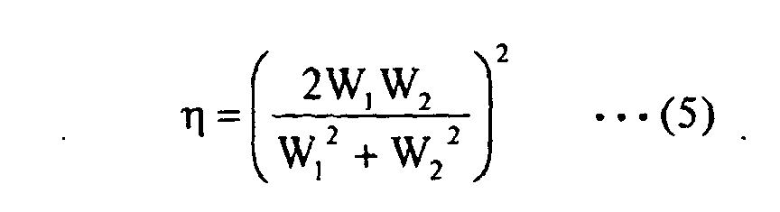
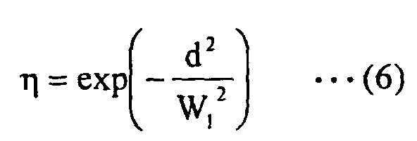
- splice efficiency ⁇ when coupling a first and a second polarization-maintaining optical fibers is typically expressed by the following Formula (4): where W 1 is a radius of the mode field 4 of the first polarization-maintaining optical fiber, W 2 is a radius of the mode field 4 of the second polarization-maintaining optical fiber, and d is an offset between cores 1 of the first and second polarization-maintaining optical fibers (axial offset).
- Formula (4) can be transformed to obtain the following Formula (5): As evident from Formula (5), the greater the difference between MFDs of the first and second polarization-maintaining optical fibers becomes, the more the splice efficiency is reduced and the more splice loss is increased.
- Formula (4) can be transformed to obtain the following Formula (6): As evident from Formula (6), even a small axial offset d will incur an increase in splice loss when the mode field diameter is small.
- Splice loss of 0.5 dB or less is considered desirable when splicing two polarization-maintaining optical fibers.
- a mode field diameter of 6 ⁇ m or greater is preferable in order to reduce splice loss caused by an axial offset of 1 ⁇ m to 0.5 dB or less.
- the distance R between the stress-applying parts 2 should be 6 ⁇ m or greater.
- Polarization-maintaining optical fibers which are employed to couple optical components used for lightwave communications are generally used in the 0.98 ⁇ m, 1.30 ⁇ m, or 1.55 ⁇ m band.
- a 0.98 ⁇ m-band polarization-maintaining optical fiber is employed, for example, as a coupling pigtail for a pump laser of an erbium-doped fiber amplifier (EDFA).
- EDFA erbium-doped fiber amplifier
- a 1.30 ⁇ m- or 1.55 ⁇ m-band polarization-maintaining optical fiber is employed, for example, as a coupling pigtail for a semiconductor laser or a modulator.
- cut-off wavelength of a polarization-maintaining optical fiber is determined by a wavelength of transmission band, and an MFD is also roughly determined.
- a typical value of an MFD of a 0.98 ⁇ m-band polarization-maintaining optical fiber which has a cladding 125 ⁇ m in diameter is 6.3 ⁇ m.
- Splice loss when this conventional polarization-maintaining optical fiber and an optical fiber having a different MFD are spliced with an axial offset of 1 ⁇ m was calculated using Formula (4), the results of which are shown in FIG. 4.
- the 0.98 ⁇ m-band polarization-maintaining optical fiber according to the present embodiment should have an MFD of 5.3 ⁇ m or greater.
- an MFD at a wavelength of 0.98 ⁇ m is preferably within a range between 5.3 ⁇ m and 6.5 ⁇ m.
- the distance R between the stress-applying parts 2 is preferably between 8.5 ⁇ m and 11 ⁇ m.
- the distance R between the stress-applying parts 2 of less than 8.5 ⁇ m is not desirable since the distance between the stress-applying part 2 and the core 1 will be too small and the mode field 4 may become deformed from a circular shape, resulting in an increase in splice loss.
- a distance R which is more than 11 ⁇ m is not desirable because polarization-maintaining performance will be deteriorated.
- a typical value of an MFD of a 1.40-1.63 ⁇ m-band polarization-maintaining optical fiber is 10.5 ⁇ m.
- Splice loss was calculated using Formula (4), the results of which are shown in FIG. 5. These results indicates that in order to reduce splice loss to 0.5 dB or less, the 1.40-1.63 ⁇ m-band polarization-maintaining optical fiber of the present embodiment should have an MFD of 8.0 ⁇ m or greater at a wavelength of 1.55 ⁇ m.
- an MFD is preferably within a range between 8.5 ⁇ m and 10.5 ⁇ m.
- the distance R between the stress-applying parts 2 is preferably between 13 ⁇ m and 16 ⁇ m.
- the distance R between the stress-applying parts 2 of less than 13 ⁇ m is not desirable since the distance between the stress-applying part 2 and the core 1 will be too small and the mode field 4 may become deformed from a circular shape, resulting in an increase in splice loss.
- a distance R which is more than 16 ⁇ m is not desirable because polarization-maintaining performance will be deteriorated.
- a typical value of an MFD of a 1.30 ⁇ m-band polarization-maintaining optical fiber is 9.0 ⁇ m.
- Splice loss was calculated using Formula (4), the results of which are shown in FIG. 6. These results indicates that in order to reduce splice loss to 0.5 dB or less, the 1.30 ⁇ m-band polarization-maintaining optical fiber of the present embodiment should have an MFD of 7.1 ⁇ m or greater at a wavelength of 1.30 ⁇ m.
- an MFD is preferably within a range between 7.1 ⁇ m and 9.0 ⁇ m.
- the distance R between the stress-applying parts 2 is preferably between 9 ⁇ m and 13 ⁇ m.
- the distance R between the stress-applying parts 2 of less than 9 ⁇ m is not desirable since the distance between the stress-applying part 2 and the core 1 will be too small and the mode field 4 may become deformed from a circular shape, resulting in an increase in splice loss.
- a distance R which is more than 13 ⁇ m is not desirable because polarization-maintaining performance will be deteriorated.
- the polarization-maintaining optical fiber according to the present invention exhibits an excellent polarization-maintaining performance and significantly low splice loss when spliced with a polarization-maintaining optical fiber having a cladding 125 ⁇ m in diameter even if the polarization-maintaining optical fiber has a small-diameter cladding of about 80 ⁇ m.
- this polarization-maintaining optical fiber in an optical fiber amplifier, a semiconductor laser, and a modulator, the bending radius of the fiber can be reduced; thus optical fiber amplifiers, semiconductor lasers and modulators can be significantly reduced in size compared to ones using conventional polarization-maintaining optical fibers.
- Polarization-maintaining optical fibers for the 0.98 ⁇ m, 1.30 ⁇ m, and 1.40-1.63 ⁇ m bands were fabricated while varying structural parameters of the fibers.
- VAD preforms including a core region made of silica doped with germanium (Ge) and a cladding region made of pure silica and have relative refractive index differences ⁇ of 0.25%, 0.35%, 0.4%, 0.45%, 0.6%, or 1.0% were fabricated.
- Core-cladding preforms for PANDA polarization-maintaining optical fibers were then obtained by depositing silica glass on the outer periphery of the preforms and sintering the preforms so that a predetermined cut-off wavelength was achieved.
- Holes of a predetermined diameter were provided using an ultrasonic drill in the core-cladding preforms at predetermined positions located at opposing sides with respect to the core region, and the inner surface of the holes were ground and polished to a mirror-smooth state to obtain drilled preforms.
- silica doped with boron (B) at a concentration of about 21 wt-% in terms of weight concentration of B 2 O 3 was deposited on an inner surface of a silica tube using the MCVD method to obtain a preform to be used for formation of stress-applying parts.
- the silica tube surrounding the preform was removed by polishing, and the outer surface of the preform was polished to a mirror-smooth state to obtain a stress-applying preform for forming stress-applying parts of the polarization-maintaining optical fibers.
- the diameter of the stress-applying preform was adjusted to be about 0.5 mm smaller than the diameter of the holes provided in the preform.
- the drawn optical fiber was coated with two ultraviolet curable acrylate resin layers to obtain an optical fiber wire.
- the diameter of the primary coating was about 122 ⁇ m and the diameter of the secondary coating was about 165 ⁇ m.
- Propagation loss of the resultant polarization-maintaining optical fibers and polarization crosstalk when wound about a shipping bobbin were determined. Fusion splice losses with a polarization-maintaining optical fiber having a cladding 125 ⁇ m in diameter were also measured.
- Tables 1-6 list the results and structural parameters of the polarization-maintaining optical fibers.
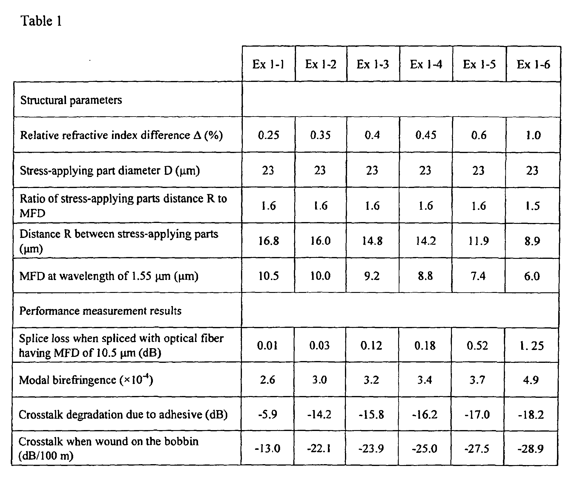
- the 1.40-1.63 ⁇ m-band polarization-maintaining optical fibers were evaluated by varying relative refractive index differences ⁇ while maintaining the ratio of the stress-applying part distance R to the MFD constant in order to maintain the effect of the stress-applying parts 2 on the mode field 4 constant. Table 1 lists the results.
- the polarization-maintaining optical fibers of Examples 1-1, 1-2, 1-3, and 1-4 exhibited significantly lower splice loss than the fibers of Examples 1-5 and Example 1-6. Furthermore, the fibers of Examples 1-2, 1-3, and 1-4 had lower polarization crosstalk than the fiber of Example 1-1 both when adhesive was applied and when the fibers were wound about a bobbin, indicating that the fibers of Examples 1-2, 1-3, and 1-4 have both excellent connectivity and satisfactory polarization-maintaining performance.
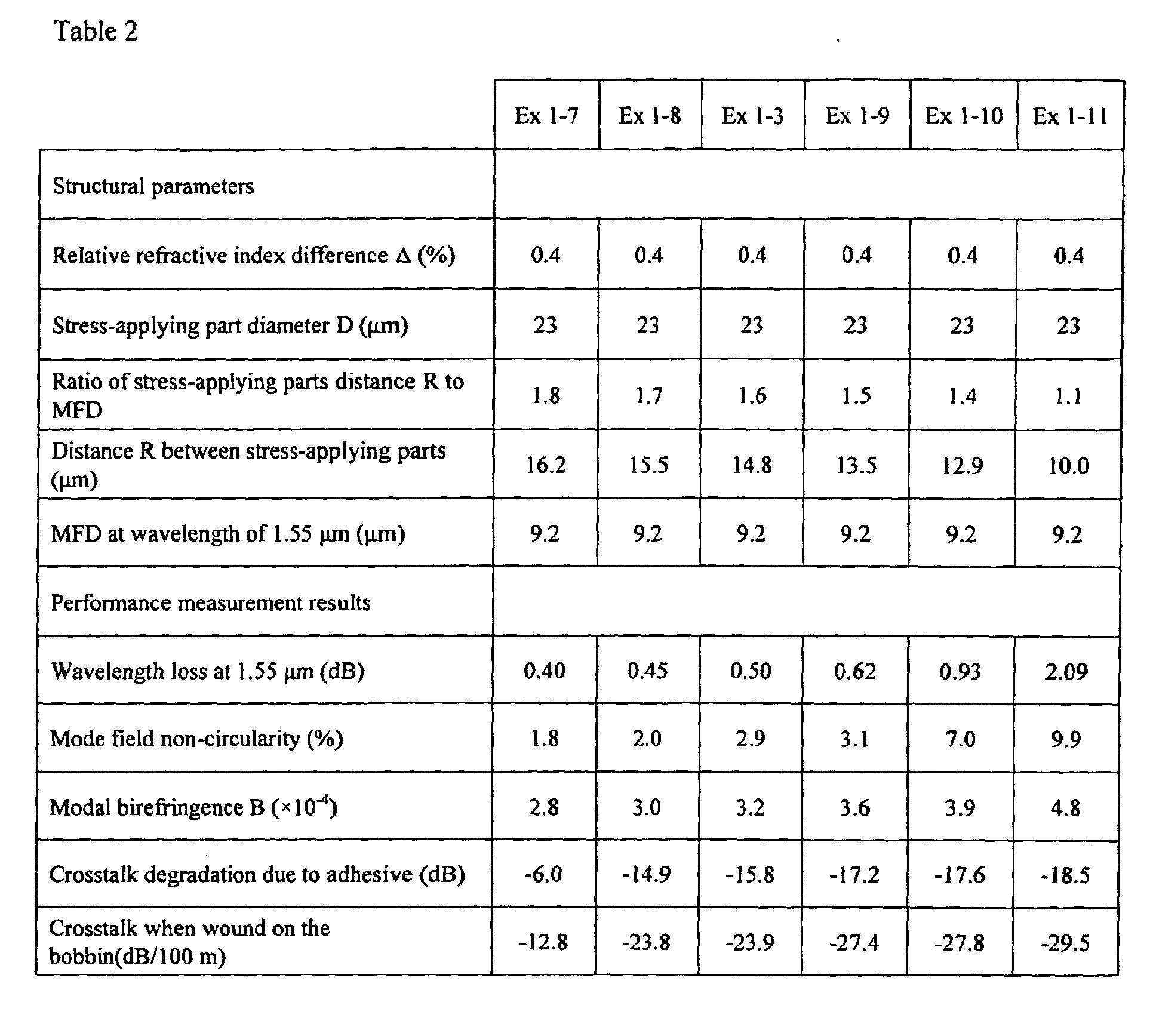
- the 1.40-1.63 ⁇ m band polarization-maintaining optical fibers were evaluated by varying the distances R between the stress-applying parts 2 while maintaining the relative refractive index differences ⁇ and the MFDs constant. Table 2 lists the results.
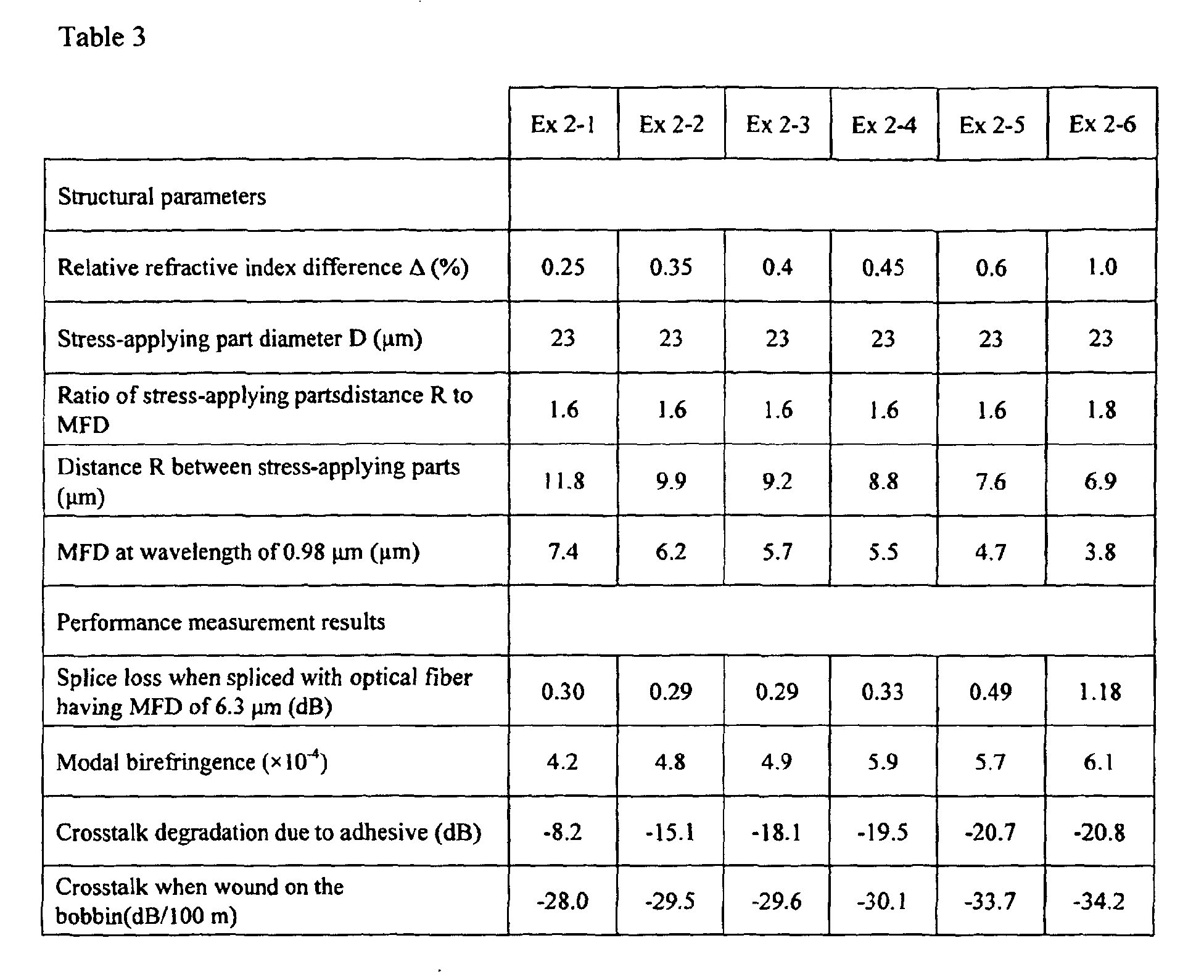
- the 0.98 ⁇ m-band polarization-maintaining optical fibers were evaluated by varying relative refractive index differences ⁇ while maintaining the ratio of the stress-applying part distance R to the MFD constant in order to maintain the effect of the stress-applying parts 2 on the mode field 4 constant.
- Table 3 lists the results.
- the polarization-maintaining optical fibers of Examples 2-1, 2-2, 2-3, and 2-4 had significantly lower splice loss than the fibers of Examples 2-5 and Example 2-6. Furthermore, the fibers of Examples 2-2, 2-3, and 2-4 exhibited lower polarization crosstalk than the fiber of Example 2-1 both when adhesive was applied and when the fibers were wound about a bobbin, indicating that the fibers of Examples 2-2, 2-3, and 2-4 have both excellent connectivity and satisfactory polarization-maintaining performance.
- the 0.98 ⁇ m-band polarization-maintaining optical fibers were evaluated by varying the distances R between the stress-applying parts 2 while maintaining the relative refractive index differences ⁇ and the MFDs constant. Table 4 lists the results.
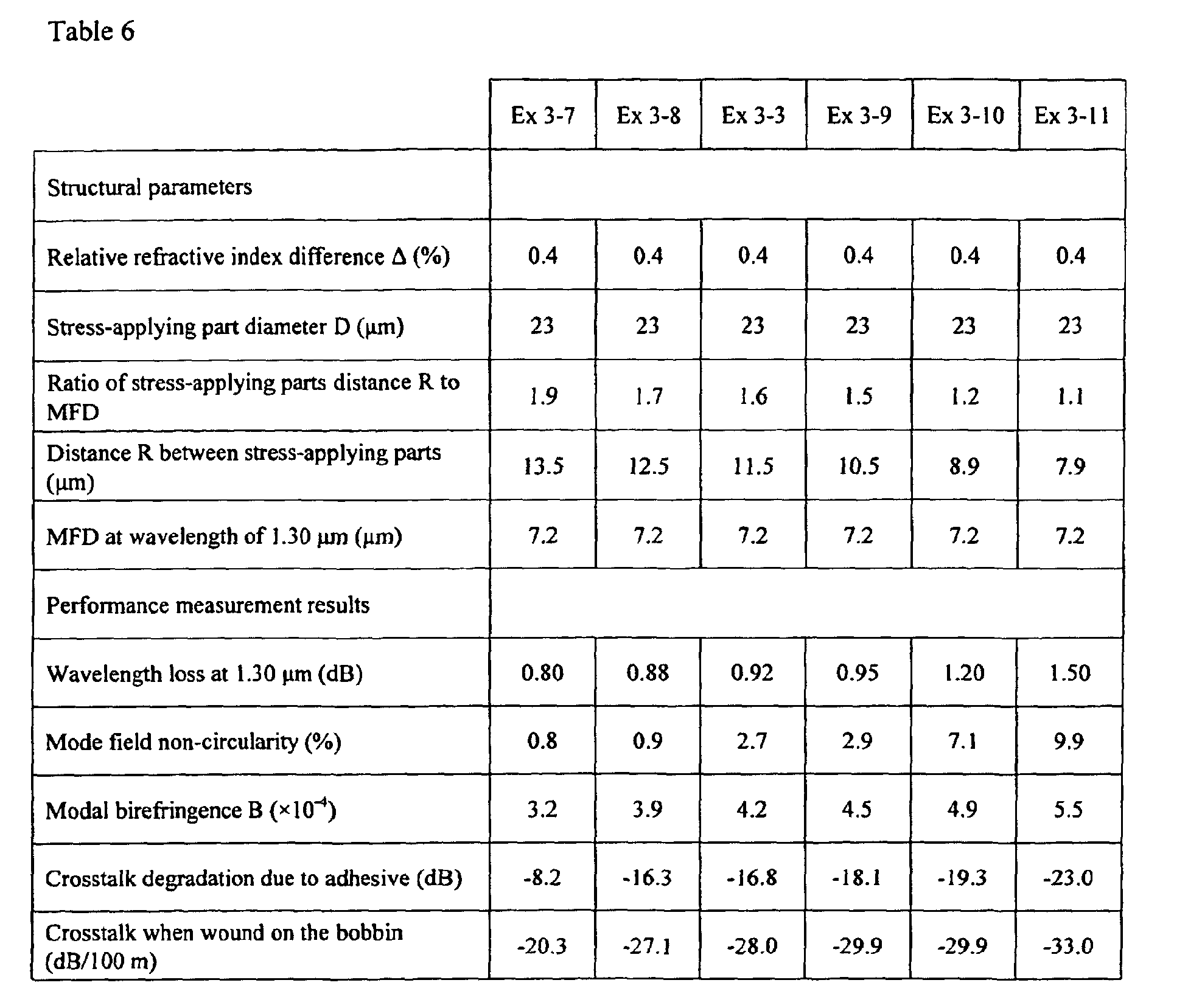
- the 1.30 ⁇ m-band polarization-maintaining optical fibers were evaluated by varying relative refractive index differences ⁇ while maintaining the ratio of the stress-applying part distance R to the MFD constant in order to maintain the effect of the stress-applying parts 2 on the mode field 4 constant.
- Table 5 lists the results.
- the polarization-maintaining optical fibers of Examples 3-1, 3-2, 3-3, and 3-4 had significantly lower splice loss than the fibers of Examples 3-5 and Example 3-6. Furthermore, the fibers of Examples 3-2, 3-3, and 3-4 exhibited lower polarization crosstalk than the fiber of Example 3-1 both when adhesive was applied and when the fibers were wound about a bobbin, indicating that the fibers of Examples 3-2, 3-3, and 3-4 have both excellent connectivity and satisfactory polarization-maintaining performance.
- the 1.30 ⁇ m band polarization-maintaining optical fibers were evaluated by varying the distances R between the stress-applying parts 2 while maintaining the relative refractive index differences ⁇ and the MFDs constant. Table 6 lists the results.
- an optical fiber amplifier was fabricated by the following procedure in order to evaluate how far an optical fiber amplifier can be reduced in size using the polarization-maintaining optical fiber according to the present invention.
- a preform for an erbium-doped optical fiber (EDF) was fabricated using the core-cladding preform mentioned above, and a polarization maintaining EDF having a cladding diameter of 80 ⁇ m was manufactured by the same fabrication method as the aforementioned examples. Table 7 lists the performances of this EDF.
- a polarization maintaining optical fiber amplifier shown in FIG. 8 was fabricated using this polarization maintaining EDF.
- This optical fiber amplifier was assembled in a typical configuration, and included a signal light input port 101, a pump light input port 102, a 980 nm to 1550 nm polarization maintaining optical coupler 103, a polarization maintaining EDF 104, a signal light output port 105, and two polarization maintaining optical isolators 106. Those components were coupled by coupling optical fibers 107.
- the outer dimension of the amplifier which included the conventional polarization-maintaining optical fibers having a outer diameter of 125 ⁇ m as coupling optical fibers 107 was 140 mm ⁇ 90 mm ⁇ 15 mm since bending radius of the optical fibers 107 could not be reduced to 20 mm or less.
- the outer dimension of the amplifier which included the 1.40-1.63 ⁇ m-band polarization-maintaining optical fibers of Example 1-3 or the 0.98 ⁇ m-band polarization-maintaining optical fiber of Example 2-3 as the coupling optical fibers 107 was 90 mm ⁇ 70 mm ⁇ 15 mm since the bending radius of coupling optical fibers 107 could be reduced to about 13 mm.
- a polarization maintaining optical fiber amplifier which has a volume about a half of a conventional amplifier could be manufactured.
- the polarization-maintaining optical fiber according to the present invention exhibits an excellent polarization-maintaining performance and significantly low splice loss when spliced with a polarization-maintaining optical fiber having a cladding 125 ⁇ m in diameter even if the polarization-maintaining optical fiber has a small-diameter cladding of 70 ⁇ m to 90 ⁇ m, more preferably 77 ⁇ m to 83 ⁇ m.
- this polarization-maintaining optical fiber in optical transmission components, e.g., an optical fiber amplifier, a semiconductor laser, and a modulator, or optical transmission or measurement devices, the bending radius of the fiber can be reduced; thus these components can be significantly reduced in size compared to ones using conventional polarization-maintaining optical fibers.
- optical transmission components e.g., an optical fiber amplifier, a semiconductor laser, and a modulator, or optical transmission or measurement devices
Landscapes
- Physics & Mathematics (AREA)
- General Physics & Mathematics (AREA)
- Optics & Photonics (AREA)
- Optical Fibers, Optical Fiber Cores, And Optical Fiber Bundles (AREA)
- Lasers (AREA)
Abstract
Description





| Structural parameters | |
| Relative refractive index difference Δ (%) | 1.3 |
| Stress-applying part diameter D (µm) | 23 |
| Ratio of stress-applying part distance R to MFD | 1.6 |
| Distance R between stress-applying parts (µm) | 8.5 |
| MFD at wavelength of 0.98 µm (µm) | 5.3 |
| Performance measurement results | |
| Modal birefringence B (× 10-4) | 4.8 |
| Crosstalk when wound on the bobbin (dB/100 m) | -30.5 |
Claims (7)
- A polarization-maintaining optical fiber comprising:wherein a diameter of the cladding is between 70 µm and 90 µm, a diameter of the stress-applying parts is between 21 µm and 32 µm, a distance between the stress-applying parts is between 6 µm and 17 µm, and a relative refractive index difference between the core and the cladding is between 0.3% and 0.5%.a core;a pair of stress-applying parts provided radially outwardly with respect to the core; anda cladding which surrounds the core and the stress-applying parts,
- The polarization-maintaining optical fiber according to claim 1, wherein the polarization-maintaining optical fiber is used for a 0.98 µm band and
the diameter of the stress-applying parts is between 22 µm and 28 µm, the distance between the stress-applying parts is between 8.5 µm and 11 µm, and a modal birefringence is 3×10⁻⁴ or higher, and a mode field diameter at a wavelength of 0.98 µm is between 5.3 µm and 6.5 µm. - The polarization-maintaining optical fiber according to claim 1, wherein the polarization-maintaining optical fiber is used for a 1.3 µm band and
the diameter of the stress-applying parts is between 22 µm and 28 µm, the distance between the stress-applying parts is between 9 µm and 13 µm, a modal birefringence is 3×10⁻⁴ or higher, a mode field diameter at a wavelength of 1.30 µm is between 7.1 µm and 9.0 µm. - The polarization-maintaining optical fiber according to claim 1, wherein the polarization-maintaining optical fiber is used for a 1.40-1.63 µm band and
the diameter of the stress-applying parts is between 22 µm and 28 µm, the distance between the stress-applying parts is between 13 µm and 16 µm, a modal birefringence is 3×10⁻⁴ or higher, and the mode field diameter at a wavelength 1.55 µm is between 8.5 µm and 10.5 µm. - An optical fiber amplifier comprising the polarization-maintaining optical fiber according to any one of claims 1 to 4.
- A semiconductor laser comprising the polarization-maintaining optical fiber according to any one of claims 1 to 4.
- A modulator comprising the polarization-maintaining optical fiber according to any one of claims 1 to 4.
Applications Claiming Priority (5)
| Application Number | Priority Date | Filing Date | Title |
|---|---|---|---|
| JP2002073194 | 2002-03-15 | ||
| JP2002073194 | 2002-03-15 | ||
| JP2003051194A JP3833621B2 (en) | 2002-03-15 | 2003-02-27 | Polarization maintaining optical fiber |
| JP2003051194 | 2003-02-27 | ||
| PCT/JP2003/003002 WO2003079075A1 (en) | 2002-03-15 | 2003-03-13 | Polarization preserving optical fiber |
Publications (3)
| Publication Number | Publication Date |
|---|---|
| EP1486804A1 true EP1486804A1 (en) | 2004-12-15 |
| EP1486804A4 EP1486804A4 (en) | 2005-06-01 |
| EP1486804B1 EP1486804B1 (en) | 2017-10-11 |
Family
ID=28043742
Family Applications (1)
| Application Number | Title | Priority Date | Filing Date |
|---|---|---|---|
| EP03712678.6A Expired - Lifetime EP1486804B1 (en) | 2002-03-15 | 2003-03-13 | Polarization preserving optical fiber |
Country Status (5)
| Country | Link |
|---|---|
| US (1) | US7289687B2 (en) |
| EP (1) | EP1486804B1 (en) |
| JP (1) | JP3833621B2 (en) |
| CN (1) | CN1323303C (en) |
| WO (1) | WO2003079075A1 (en) |
Families Citing this family (30)
| Publication number | Priority date | Publication date | Assignee | Title |
|---|---|---|---|---|
| JP3833621B2 (en) * | 2002-03-15 | 2006-10-18 | 株式会社フジクラ | Polarization maintaining optical fiber |
| JP2004207677A (en) * | 2002-11-07 | 2004-07-22 | Nippon Telegr & Teleph Corp <Ntt> | Optical devices and optical fibers for amplification media |
| US7280730B2 (en) | 2004-01-16 | 2007-10-09 | Imra America, Inc. | Large core holey fibers |
| US7787729B2 (en) | 2005-05-20 | 2010-08-31 | Imra America, Inc. | Single mode propagation in fibers and rods with large leakage channels |
| JP2007010896A (en) * | 2005-06-29 | 2007-01-18 | Fujikura Ltd | Polarization maintaining optical fiber and optical fiber gyro |
| JP4244998B2 (en) * | 2006-02-08 | 2009-03-25 | 日本電気硝子株式会社 | Method for manufacturing capillary tube for fixing optical fiber |
| CN103246014B (en) | 2007-09-26 | 2015-12-23 | Imra美国公司 | Glass large-core optical fibers |
| EP2597500A1 (en) * | 2010-08-18 | 2013-05-29 | Fujikura, Ltd. | Polarization maintaining fiber and optical fiber sensor using same |
| EP2626730B1 (en) | 2010-10-05 | 2021-08-18 | Fujikura Ltd. | Polarization-maintaining optical fiber |
| CN102096145B (en) * | 2010-12-31 | 2012-11-07 | 北京交通大学 | Multi-core polarization maintaining fiber and manufacturing method thereof |
| CN102213791B (en) * | 2011-07-12 | 2014-11-26 | 武汉长盈通光电技术有限公司 | Panda small-diameter polarization-maintaining optical fiber |
| CN102531378B (en) * | 2012-03-12 | 2014-12-10 | 武汉烽火锐光科技有限公司 | Boron-doped stress bar for manufacturing polarization-preserving fiber and manufacturing method for boron-doped stress bar |
| GB2516088A (en) * | 2013-07-11 | 2015-01-14 | Fibercore Ltd | Optical Fiber |
| JP2015184371A (en) | 2014-03-20 | 2015-10-22 | 株式会社フジクラ | Polarization holding optical fiber |
| CN103954240B (en) * | 2014-04-10 | 2016-09-14 | 浙江大学 | A kind of based on spectral coverage OCT imaging systematic survey polarization maintaining optical fibre torsion method |
| US11156769B2 (en) | 2016-12-14 | 2021-10-26 | Ofs Fitel, Llc | Polarization-maintaining fiber device supporting propagation in large mode field diameters |
| US10261246B2 (en) | 2016-12-14 | 2019-04-16 | Ofs Fitel, Llc | Polarization-maintaining fiber device supporting propagation in large mode field diameters |
| JP6696936B2 (en) * | 2017-05-30 | 2020-05-20 | 古河電気工業株式会社 | Optical fiber terminal structure, optical element connection structure, and method for manufacturing optical fiber terminal structure |
| CN109471217A (en) * | 2018-12-18 | 2019-03-15 | 武汉理工大学 | One kind being easy to polarized diplopore optical fiber |
| US12431682B2 (en) * | 2020-09-03 | 2025-09-30 | Acacia Technology, Inc. | Erbium doped fiber isolator components |
| DK4292990T3 (en) * | 2021-02-12 | 2025-12-08 | Sumitomo Electric Industries | POLARIZATION-MAINTAINING OPTICAL FIBER AND METHOD FOR MANUFACTURING POLARIZATION-MAINTAINING OPTICAL FIBER |
| WO2023119925A1 (en) * | 2021-12-24 | 2023-06-29 | 住友電気工業株式会社 | Bent optical fiber, method for manufacturing bent optical fiber, and optical connection component |
| JPWO2023145862A1 (en) * | 2022-01-31 | 2023-08-03 | ||
| JPWO2023145863A1 (en) * | 2022-01-31 | 2023-08-03 | ||
| CA3224744A1 (en) * | 2023-01-13 | 2025-06-30 | Thorlabs, Inc. | Single mode wideband polarization maintaining fiber coupler |
| WO2025028627A1 (en) * | 2023-08-02 | 2025-02-06 | 株式会社フジクラ | Polarization-maintaining fiber |
| CN121605331A (en) * | 2023-08-02 | 2026-03-03 | 株式会社藤仓 | Polarization maintaining optical fiber |
| CN121605333A (en) * | 2023-08-02 | 2026-03-03 | 株式会社藤仓 | Polarization maintaining optical fiber |
| WO2025028628A1 (en) * | 2023-08-02 | 2025-02-06 | 株式会社フジクラ | Polarization-maintaining fiber |
| WO2025159182A1 (en) * | 2024-01-26 | 2025-07-31 | 株式会社フジクラ | Polarization-maintaining fiber |
Family Cites Families (23)
| Publication number | Priority date | Publication date | Assignee | Title |
|---|---|---|---|---|
| CA1177297A (en) | 1981-03-30 | 1984-11-06 | Michael G. Blankenship | Polarization retaining single-mode optical fibers and methods of making |
| US4478489A (en) | 1981-04-13 | 1984-10-23 | Corning Glass Works | Polarization retaining single-mode optical waveguide |
| JPS60125826A (en) * | 1983-12-09 | 1985-07-05 | Showa Electric Wire & Cable Co Ltd | Optical modulator for polarization plane maintaining fiber |
| JPS6151122A (en) * | 1984-08-21 | 1986-03-13 | Nippon Telegr & Teleph Corp <Ntt> | Fiber type optical modulator |
| CA1302759C (en) * | 1986-11-28 | 1992-06-09 | Kuniharu Himeno | Optical fiber coupler and process for manufacturing same |
| JP3006205B2 (en) * | 1991-09-17 | 2000-02-07 | 住友電気工業株式会社 | Optical fiber polarizer |
| JPH0659154A (en) * | 1992-08-11 | 1994-03-04 | Fujitsu Ltd | Polarization coupler manufacturing method and polarization coupler |
| EP0637762B1 (en) * | 1993-02-25 | 2000-05-24 | Fujikura Ltd. | Polarized wave holding optical fiber, production method therefor, connection method therefor, optical amplifier, laser oscillator and polarized wave holding optical fiber coupler |
| JPH08254668A (en) * | 1995-03-17 | 1996-10-01 | Fujitsu Ltd | Laser diode module and depolarizer |
| JP3630767B2 (en) * | 1995-05-15 | 2005-03-23 | 株式会社フジクラ | Rare earth doped polarization maintaining optical fiber |
| JP2002541508A (en) * | 1999-03-30 | 2002-12-03 | クリスタル フィブレ アクティーゼルスカブ | Polarization maintaining optical fiber |
| US6463195B1 (en) * | 1999-05-31 | 2002-10-08 | Fujikura Ltd. | Method of manufacturing polarization-maintaining optical fiber coupler |
| JP3505533B2 (en) * | 1999-06-30 | 2004-03-08 | 古河電気工業株式会社 | Optical fiber |
| JP2001056416A (en) * | 1999-08-20 | 2001-02-27 | Fujikura Ltd | Polarization maintaining optical fiber and polarization maintaining optical fiber component |
| JP3857868B2 (en) | 1999-09-16 | 2006-12-13 | 古河電気工業株式会社 | Semiconductor laser module |
| JP2002214465A (en) * | 2001-01-17 | 2002-07-31 | Fujikura Ltd | Polarization-maintaining optical fiber |
| JP2002296438A (en) * | 2001-03-29 | 2002-10-09 | Fujikura Ltd | Polarization-maintaining optical fiber and method of manufacturing base material thereof |
| JP3903987B2 (en) * | 2002-03-04 | 2007-04-11 | 住友電気工業株式会社 | Polarization-maintaining optical fiber manufacturing method |
| JP3833621B2 (en) * | 2002-03-15 | 2006-10-18 | 株式会社フジクラ | Polarization maintaining optical fiber |
| US7116887B2 (en) * | 2002-03-19 | 2006-10-03 | Nufern | Optical fiber |
| US7346258B2 (en) * | 2002-07-09 | 2008-03-18 | Fujikura Ltd. | Optical fiber and optical fiber coupler, erbium-doped optical fiber amplifier, and optical waveguide using the same |
| US7110647B2 (en) * | 2003-01-17 | 2006-09-19 | Nufern | Multimode polarization maintaining double clad fiber |
| JP2007010896A (en) * | 2005-06-29 | 2007-01-18 | Fujikura Ltd | Polarization maintaining optical fiber and optical fiber gyro |
-
2003
- 2003-02-27 JP JP2003051194A patent/JP3833621B2/en not_active Expired - Lifetime
- 2003-03-13 CN CNB038058553A patent/CN1323303C/en not_active Expired - Lifetime
- 2003-03-13 EP EP03712678.6A patent/EP1486804B1/en not_active Expired - Lifetime
- 2003-03-13 WO PCT/JP2003/003002 patent/WO2003079075A1/en not_active Ceased
-
2004
- 2004-09-10 US US10/937,495 patent/US7289687B2/en not_active Expired - Lifetime
Also Published As
| Publication number | Publication date |
|---|---|
| US20050031280A1 (en) | 2005-02-10 |
| JP2003337238A (en) | 2003-11-28 |
| JP3833621B2 (en) | 2006-10-18 |
| EP1486804B1 (en) | 2017-10-11 |
| US7289687B2 (en) | 2007-10-30 |
| CN1323303C (en) | 2007-06-27 |
| CN1643418A (en) | 2005-07-20 |
| EP1486804A4 (en) | 2005-06-01 |
| WO2003079075A1 (en) | 2003-09-25 |
Similar Documents
| Publication | Publication Date | Title |
|---|---|---|
| US7289687B2 (en) | Polarization-maintaining optical fiber | |
| US8958677B2 (en) | Polarization-maintaining optical fiber | |
| US7809223B2 (en) | Polarization-maintaining optical fiber, method of manufacturing polarization-maintaining optical-fiber connecting portion, and polarization-maintaining optical-fiber connecting portion | |
| US7711238B2 (en) | Optical fiber and optical fiber coupler, erbium-doped optical fiber amplifier, and optical waveguide using the same | |
| US7164830B2 (en) | Nonlinear optical fiber and optical signal processing apparatus using the optical fiber | |
| JP2010061170A (en) | Optical fiber module | |
| WO2016190297A1 (en) | Optical fiber | |
| US7430353B2 (en) | Polarization-maintaining optical fiber and optical fiber gyro | |
| JP5871423B2 (en) | Optical fiber module | |
| JP2003004973A (en) | Optical fiber coupler and optical fiber for optical fiber coupler | |
| EP1533634B1 (en) | Optical fiber, optical fiber coupler including the same, erbium loaded optical fiber amplifier and light guide | |
| JP2007521513A (en) | High performance index dispersion compensating fiber for standard single mode fiber and transmission system using the dispersion compensating fiber | |
| KR20200081597A (en) | Method for manufacturing polarization maintaining optical fiber | |
| JP2003029072A (en) | Polarization-maintaining optical fiber | |
| RU2223522C2 (en) | Single-mode single-polarization light guide | |
| JPH0350505A (en) | Single polarization optical fiber |
Legal Events
| Date | Code | Title | Description |
|---|---|---|---|
| PUAI | Public reference made under article 153(3) epc to a published international application that has entered the european phase |
Free format text: ORIGINAL CODE: 0009012 |
|
| 17P | Request for examination filed |
Effective date: 20040913 |
|
| AK | Designated contracting states |
Kind code of ref document: A1 Designated state(s): AT BE BG CH CY CZ DE DK EE ES FI FR GB GR HU IE IT LI LU MC NL PT RO SE SI SK TR |
|
| A4 | Supplementary search report drawn up and despatched |
Effective date: 20050414 |
|
| RIC1 | Information provided on ipc code assigned before grant |
Ipc: 7G 02B 6/10 A Ipc: 7G 02B 6/17 B |
|
| 17Q | First examination report despatched |
Effective date: 20060801 |
|
| REG | Reference to a national code |
Ref country code: DE Ref legal event code: R079 Ref document number: 60350684 Country of ref document: DE Free format text: PREVIOUS MAIN CLASS: G02B0006100000 Ipc: G02B0006024000 |
|
| GRAP | Despatch of communication of intention to grant a patent |
Free format text: ORIGINAL CODE: EPIDOSNIGR1 |
|
| STAA | Information on the status of an ep patent application or granted ep patent |
Free format text: STATUS: GRANT OF PATENT IS INTENDED |
|
| RIC1 | Information provided on ipc code assigned before grant |
Ipc: G02B 6/024 20060101AFI20170612BHEP |
|
| INTG | Intention to grant announced |
Effective date: 20170705 |
|
| GRAS | Grant fee paid |
Free format text: ORIGINAL CODE: EPIDOSNIGR3 |
|
| GRAA | (expected) grant |
Free format text: ORIGINAL CODE: 0009210 |
|
| STAA | Information on the status of an ep patent application or granted ep patent |
Free format text: STATUS: THE PATENT HAS BEEN GRANTED |
|
| AK | Designated contracting states |
Kind code of ref document: B1 Designated state(s): DE FR GB IT |
|
| REG | Reference to a national code |
Ref country code: GB Ref legal event code: FG4D |
|
| RIN1 | Information on inventor provided before grant (corrected) |
Inventor name: ITOH, TATSUYA, C/O FUJIKURA LTD, SAKURA WORKS Inventor name: HIMENO, KUNIHARU, C/O FUJIKURA LTD, SAKURA WORKS Inventor name: SAKAGUCHI, YUKIHIRO, C/O FUJIKURA LTD, SAKURA WORK Inventor name: IZOE, KATSUAKI, C/O FUJIKURA LTD, SAKURA WORKS |
|
| REG | Reference to a national code |
Ref country code: DE Ref legal event code: R096 Ref document number: 60350684 Country of ref document: DE |
|
| REG | Reference to a national code |
Ref country code: FR Ref legal event code: PLFP Year of fee payment: 16 |
|
| REG | Reference to a national code |
Ref country code: DE Ref legal event code: R097 Ref document number: 60350684 Country of ref document: DE |
|
| PLBE | No opposition filed within time limit |
Free format text: ORIGINAL CODE: 0009261 |
|
| STAA | Information on the status of an ep patent application or granted ep patent |
Free format text: STATUS: NO OPPOSITION FILED WITHIN TIME LIMIT |
|
| 26N | No opposition filed |
Effective date: 20180712 |
|
| PGFP | Annual fee paid to national office [announced via postgrant information from national office to epo] |
Ref country code: GB Payment date: 20220127 Year of fee payment: 20 Ref country code: DE Payment date: 20220203 Year of fee payment: 20 |
|
| PGFP | Annual fee paid to national office [announced via postgrant information from national office to epo] |
Ref country code: IT Payment date: 20220210 Year of fee payment: 20 Ref country code: FR Payment date: 20220209 Year of fee payment: 20 |
|
| REG | Reference to a national code |
Ref country code: DE Ref legal event code: R071 Ref document number: 60350684 Country of ref document: DE |
|
| REG | Reference to a national code |
Ref country code: GB Ref legal event code: PE20 Expiry date: 20230312 |
|
| PG25 | Lapsed in a contracting state [announced via postgrant information from national office to epo] |
Ref country code: GB Free format text: LAPSE BECAUSE OF EXPIRATION OF PROTECTION Effective date: 20230312 |