EP1486740A1 - Pressure control device of air conditioner and air conditioner having the device - Google Patents
Pressure control device of air conditioner and air conditioner having the device Download PDFInfo
- Publication number
- EP1486740A1 EP1486740A1 EP03708530A EP03708530A EP1486740A1 EP 1486740 A1 EP1486740 A1 EP 1486740A1 EP 03708530 A EP03708530 A EP 03708530A EP 03708530 A EP03708530 A EP 03708530A EP 1486740 A1 EP1486740 A1 EP 1486740A1
- Authority
- EP
- European Patent Office
- Prior art keywords
- pressure
- heat exchanger
- indoor
- refrigerant
- gaseous refrigerant
- Prior art date
- Legal status (The legal status is an assumption and is not a legal conclusion. Google has not performed a legal analysis and makes no representation as to the accuracy of the status listed.)
- Granted
Links
Images



Classifications
-
- F—MECHANICAL ENGINEERING; LIGHTING; HEATING; WEAPONS; BLASTING
- F24—HEATING; RANGES; VENTILATING
- F24F—AIR-CONDITIONING; AIR-HUMIDIFICATION; VENTILATION; USE OF AIR CURRENTS FOR SCREENING
- F24F1/00—Room units for air-conditioning, e.g. separate or self-contained units or units receiving primary air from a central station
- F24F1/06—Separate outdoor units, e.g. outdoor unit to be linked to a separate room comprising a compressor and a heat exchanger
- F24F1/26—Refrigerant piping
- F24F1/32—Refrigerant piping for connecting the separate outdoor units to indoor units
-
- F—MECHANICAL ENGINEERING; LIGHTING; HEATING; WEAPONS; BLASTING
- F25—REFRIGERATION OR COOLING; COMBINED HEATING AND REFRIGERATION SYSTEMS; HEAT PUMP SYSTEMS; MANUFACTURE OR STORAGE OF ICE; LIQUEFACTION SOLIDIFICATION OF GASES
- F25B—REFRIGERATION MACHINES, PLANTS OR SYSTEMS; COMBINED HEATING AND REFRIGERATION SYSTEMS; HEAT PUMP SYSTEMS
- F25B13/00—Compression machines, plants or systems, with reversible cycle
-
- F—MECHANICAL ENGINEERING; LIGHTING; HEATING; WEAPONS; BLASTING
- F24—HEATING; RANGES; VENTILATING
- F24F—AIR-CONDITIONING; AIR-HUMIDIFICATION; VENTILATION; USE OF AIR CURRENTS FOR SCREENING
- F24F1/00—Room units for air-conditioning, e.g. separate or self-contained units or units receiving primary air from a central station
-
- F—MECHANICAL ENGINEERING; LIGHTING; HEATING; WEAPONS; BLASTING
- F25—REFRIGERATION OR COOLING; COMBINED HEATING AND REFRIGERATION SYSTEMS; HEAT PUMP SYSTEMS; MANUFACTURE OR STORAGE OF ICE; LIQUEFACTION SOLIDIFICATION OF GASES
- F25B—REFRIGERATION MACHINES, PLANTS OR SYSTEMS; COMBINED HEATING AND REFRIGERATION SYSTEMS; HEAT PUMP SYSTEMS
- F25B41/00—Fluid-circulation arrangements
- F25B41/20—Disposition of valves, e.g. of on-off valves or flow control valves
- F25B41/22—Disposition of valves, e.g. of on-off valves or flow control valves between evaporator and compressor
-
- F—MECHANICAL ENGINEERING; LIGHTING; HEATING; WEAPONS; BLASTING
- F25—REFRIGERATION OR COOLING; COMBINED HEATING AND REFRIGERATION SYSTEMS; HEAT PUMP SYSTEMS; MANUFACTURE OR STORAGE OF ICE; LIQUEFACTION SOLIDIFICATION OF GASES
- F25B—REFRIGERATION MACHINES, PLANTS OR SYSTEMS; COMBINED HEATING AND REFRIGERATION SYSTEMS; HEAT PUMP SYSTEMS
- F25B41/00—Fluid-circulation arrangements
- F25B41/30—Expansion means; Dispositions thereof
- F25B41/39—Dispositions with two or more expansion means arranged in series, i.e. multi-stage expansion, on a refrigerant line leading to the same evaporator
-
- F—MECHANICAL ENGINEERING; LIGHTING; HEATING; WEAPONS; BLASTING
- F25—REFRIGERATION OR COOLING; COMBINED HEATING AND REFRIGERATION SYSTEMS; HEAT PUMP SYSTEMS; MANUFACTURE OR STORAGE OF ICE; LIQUEFACTION SOLIDIFICATION OF GASES
- F25B—REFRIGERATION MACHINES, PLANTS OR SYSTEMS; COMBINED HEATING AND REFRIGERATION SYSTEMS; HEAT PUMP SYSTEMS
- F25B47/00—Arrangements for preventing or removing deposits or corrosion, not provided for in another subclass
- F25B47/006—Arrangements for preventing or removing deposits or corrosion, not provided for in another subclass for preventing frost
-
- F—MECHANICAL ENGINEERING; LIGHTING; HEATING; WEAPONS; BLASTING
- F25—REFRIGERATION OR COOLING; COMBINED HEATING AND REFRIGERATION SYSTEMS; HEAT PUMP SYSTEMS; MANUFACTURE OR STORAGE OF ICE; LIQUEFACTION SOLIDIFICATION OF GASES
- F25B—REFRIGERATION MACHINES, PLANTS OR SYSTEMS; COMBINED HEATING AND REFRIGERATION SYSTEMS; HEAT PUMP SYSTEMS
- F25B2313/00—Compression machines, plants or systems with reversible cycle not otherwise provided for
- F25B2313/005—Outdoor unit expansion valves
-
- F—MECHANICAL ENGINEERING; LIGHTING; HEATING; WEAPONS; BLASTING
- F25—REFRIGERATION OR COOLING; COMBINED HEATING AND REFRIGERATION SYSTEMS; HEAT PUMP SYSTEMS; MANUFACTURE OR STORAGE OF ICE; LIQUEFACTION SOLIDIFICATION OF GASES
- F25B—REFRIGERATION MACHINES, PLANTS OR SYSTEMS; COMBINED HEATING AND REFRIGERATION SYSTEMS; HEAT PUMP SYSTEMS
- F25B2313/00—Compression machines, plants or systems with reversible cycle not otherwise provided for
- F25B2313/007—Compression machines, plants or systems with reversible cycle not otherwise provided for three pipes connecting the outdoor side to the indoor side with multiple indoor units
-
- F—MECHANICAL ENGINEERING; LIGHTING; HEATING; WEAPONS; BLASTING
- F25—REFRIGERATION OR COOLING; COMBINED HEATING AND REFRIGERATION SYSTEMS; HEAT PUMP SYSTEMS; MANUFACTURE OR STORAGE OF ICE; LIQUEFACTION SOLIDIFICATION OF GASES
- F25B—REFRIGERATION MACHINES, PLANTS OR SYSTEMS; COMBINED HEATING AND REFRIGERATION SYSTEMS; HEAT PUMP SYSTEMS
- F25B2313/00—Compression machines, plants or systems with reversible cycle not otherwise provided for
- F25B2313/023—Compression machines, plants or systems with reversible cycle not otherwise provided for using multiple indoor units
- F25B2313/0231—Compression machines, plants or systems with reversible cycle not otherwise provided for using multiple indoor units with simultaneous cooling and heating
-
- F—MECHANICAL ENGINEERING; LIGHTING; HEATING; WEAPONS; BLASTING
- F25—REFRIGERATION OR COOLING; COMBINED HEATING AND REFRIGERATION SYSTEMS; HEAT PUMP SYSTEMS; MANUFACTURE OR STORAGE OF ICE; LIQUEFACTION SOLIDIFICATION OF GASES
- F25B—REFRIGERATION MACHINES, PLANTS OR SYSTEMS; COMBINED HEATING AND REFRIGERATION SYSTEMS; HEAT PUMP SYSTEMS
- F25B2313/00—Compression machines, plants or systems with reversible cycle not otherwise provided for
- F25B2313/023—Compression machines, plants or systems with reversible cycle not otherwise provided for using multiple indoor units
- F25B2313/0233—Compression machines, plants or systems with reversible cycle not otherwise provided for using multiple indoor units in parallel arrangements
- F25B2313/02331—Compression machines, plants or systems with reversible cycle not otherwise provided for using multiple indoor units in parallel arrangements during cooling
-
- F—MECHANICAL ENGINEERING; LIGHTING; HEATING; WEAPONS; BLASTING
- F25—REFRIGERATION OR COOLING; COMBINED HEATING AND REFRIGERATION SYSTEMS; HEAT PUMP SYSTEMS; MANUFACTURE OR STORAGE OF ICE; LIQUEFACTION SOLIDIFICATION OF GASES
- F25B—REFRIGERATION MACHINES, PLANTS OR SYSTEMS; COMBINED HEATING AND REFRIGERATION SYSTEMS; HEAT PUMP SYSTEMS
- F25B2313/00—Compression machines, plants or systems with reversible cycle not otherwise provided for
- F25B2313/023—Compression machines, plants or systems with reversible cycle not otherwise provided for using multiple indoor units
- F25B2313/0233—Compression machines, plants or systems with reversible cycle not otherwise provided for using multiple indoor units in parallel arrangements
- F25B2313/02334—Compression machines, plants or systems with reversible cycle not otherwise provided for using multiple indoor units in parallel arrangements during heating
-
- F—MECHANICAL ENGINEERING; LIGHTING; HEATING; WEAPONS; BLASTING
- F25—REFRIGERATION OR COOLING; COMBINED HEATING AND REFRIGERATION SYSTEMS; HEAT PUMP SYSTEMS; MANUFACTURE OR STORAGE OF ICE; LIQUEFACTION SOLIDIFICATION OF GASES
- F25B—REFRIGERATION MACHINES, PLANTS OR SYSTEMS; COMBINED HEATING AND REFRIGERATION SYSTEMS; HEAT PUMP SYSTEMS
- F25B2313/00—Compression machines, plants or systems with reversible cycle not otherwise provided for
- F25B2313/023—Compression machines, plants or systems with reversible cycle not otherwise provided for using multiple indoor units
- F25B2313/0234—Compression machines, plants or systems with reversible cycle not otherwise provided for using multiple indoor units in series arrangements
- F25B2313/02344—Compression machines, plants or systems with reversible cycle not otherwise provided for using multiple indoor units in series arrangements during heating
-
- F—MECHANICAL ENGINEERING; LIGHTING; HEATING; WEAPONS; BLASTING
- F25—REFRIGERATION OR COOLING; COMBINED HEATING AND REFRIGERATION SYSTEMS; HEAT PUMP SYSTEMS; MANUFACTURE OR STORAGE OF ICE; LIQUEFACTION SOLIDIFICATION OF GASES
- F25B—REFRIGERATION MACHINES, PLANTS OR SYSTEMS; COMBINED HEATING AND REFRIGERATION SYSTEMS; HEAT PUMP SYSTEMS
- F25B2313/00—Compression machines, plants or systems with reversible cycle not otherwise provided for
- F25B2313/025—Compression machines, plants or systems with reversible cycle not otherwise provided for using multiple outdoor units
-
- F—MECHANICAL ENGINEERING; LIGHTING; HEATING; WEAPONS; BLASTING
- F25—REFRIGERATION OR COOLING; COMBINED HEATING AND REFRIGERATION SYSTEMS; HEAT PUMP SYSTEMS; MANUFACTURE OR STORAGE OF ICE; LIQUEFACTION SOLIDIFICATION OF GASES
- F25B—REFRIGERATION MACHINES, PLANTS OR SYSTEMS; COMBINED HEATING AND REFRIGERATION SYSTEMS; HEAT PUMP SYSTEMS
- F25B2313/00—Compression machines, plants or systems with reversible cycle not otherwise provided for
- F25B2313/031—Sensor arrangements
- F25B2313/0312—Pressure sensors near the indoor heat exchanger
-
- F—MECHANICAL ENGINEERING; LIGHTING; HEATING; WEAPONS; BLASTING
- F25—REFRIGERATION OR COOLING; COMBINED HEATING AND REFRIGERATION SYSTEMS; HEAT PUMP SYSTEMS; MANUFACTURE OR STORAGE OF ICE; LIQUEFACTION SOLIDIFICATION OF GASES
- F25B—REFRIGERATION MACHINES, PLANTS OR SYSTEMS; COMBINED HEATING AND REFRIGERATION SYSTEMS; HEAT PUMP SYSTEMS
- F25B2400/00—Component parts or details not otherwise provided for in this subclass
- F25B2400/13—Economisers
-
- F—MECHANICAL ENGINEERING; LIGHTING; HEATING; WEAPONS; BLASTING
- F25—REFRIGERATION OR COOLING; COMBINED HEATING AND REFRIGERATION SYSTEMS; HEAT PUMP SYSTEMS; MANUFACTURE OR STORAGE OF ICE; LIQUEFACTION SOLIDIFICATION OF GASES
- F25B—REFRIGERATION MACHINES, PLANTS OR SYSTEMS; COMBINED HEATING AND REFRIGERATION SYSTEMS; HEAT PUMP SYSTEMS
- F25B2500/00—Problems to be solved
- F25B2500/31—Low ambient temperatures
-
- F—MECHANICAL ENGINEERING; LIGHTING; HEATING; WEAPONS; BLASTING
- F25—REFRIGERATION OR COOLING; COMBINED HEATING AND REFRIGERATION SYSTEMS; HEAT PUMP SYSTEMS; MANUFACTURE OR STORAGE OF ICE; LIQUEFACTION SOLIDIFICATION OF GASES
- F25B—REFRIGERATION MACHINES, PLANTS OR SYSTEMS; COMBINED HEATING AND REFRIGERATION SYSTEMS; HEAT PUMP SYSTEMS
- F25B2600/00—Control issues
- F25B2600/25—Control of valves
- F25B2600/2513—Expansion valves
-
- F—MECHANICAL ENGINEERING; LIGHTING; HEATING; WEAPONS; BLASTING
- F25—REFRIGERATION OR COOLING; COMBINED HEATING AND REFRIGERATION SYSTEMS; HEAT PUMP SYSTEMS; MANUFACTURE OR STORAGE OF ICE; LIQUEFACTION SOLIDIFICATION OF GASES
- F25B—REFRIGERATION MACHINES, PLANTS OR SYSTEMS; COMBINED HEATING AND REFRIGERATION SYSTEMS; HEAT PUMP SYSTEMS
- F25B2600/00—Control issues
- F25B2600/25—Control of valves
- F25B2600/2515—Flow valves
Definitions
- the present invention relates to a pressure adjusting device for an air conditioning system and, more particularly, to a pressure adjusting device for adjusting the pressure in the indoor heat exchanger of an air conditioning system provided with an outdoor unit having a compressor and an outdoor heat exchanger, an indoor unit having an indoor heat exchanger, and a gaseous refrigerant pipe connecting the indoor heat exchanger to the compressor.
- the invention also relates to an air conditioning system equipped with such a pressure adjusting device.
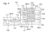
- the air conditioning system 101 has one air-cooled outdoor unit 102 and a plurality of (more specifically, three) indoor units 103, 104, 105 and is used to air-condition an office or the like.
- the outdoor unit 102 is equipped with a compressor 111 and an outdoor heat exchanger 112 and is installed outdoors.
- the indoor units 103, 104, 105 are each equipped with an expansion valve 113, 114, 115 and an indoor heat exchanger 123, 124, 125 and installed in an indoor room 133, 134, 135.
- the outdoor heat exchanger 112 and the expansion valves 113, 114, 115 are connected together by a liquid refrigerant pipe 116.
- the indoor heat exchangers 123, 124, 125 and the compressor 111 are connected together by a gaseous refrigerant pipe 117.
- the gaseous refrigerant is compressed by the compressor 111 from the state at point A0 to a prescribed pressure Pd0 (see point B0 in Figures 4 and 5) before being delivered to the outdoor heat exchanger 112.
- Pd0 a prescribed pressure
- the gaseous refrigerant exchanges heat with the outside air and condenses, changing to a liquid refrigerant state (see point C0 in Figures 4 and 5).
- This condensed liquid refrigerant is delivered from the outdoor heat exchanger 112 to the expansion valves 113, 114, 115 of the indoor units 103, 104, 105 through the liquid refrigerant pipe 116 and the pressure of the liquid refrigerant is reduced to Ps0 (see point D0 in Figures 4 and 5) by the expansion valves 113, 114, 115.
- the pressure-reduced refrigerant exchanges heat with the air inside each respective room and evaporates, changing to a gaseous refrigerant state (see point A0 in Figures 4 and 5).
- the evaporation temperature of the refrigerant at the indoor heat exchangers 123, 124, 125 is the temperature T0 corresponding to the pressure Ps0.
- the gaseous refrigerant is drawn into the compressor 111 through the gaseous refrigerant pipe 117. In this way, the air inside the rooms is cooled.
- the refrigerant evaporated in the indoor heat exchangers 123, 124, 125 of the conventional air conditioning system 101 partially changes to a liquid (see point E0 in Figures 4 and 5) by the time it reaches the compressor 111 through the gaseous refrigerant pipe 117 after leaving the outlets of the indoor heat exchangers 123, 124, 125 (see point A0 in Figures 4 and 5).
- this partially liquefied refrigerant is drawn into the compressor 111, such problems as damage to the compressor 111 and insufficient intake of gaseous refrigerant occur.
- the openings of the expansion valves 113, 114, 115 are adjusted such that the refrigerant pressure in the indoor heat exchangers 123, 124, 125 is lowered (see point D1 and pressure Ps1 in Figure 5) and the evaporation temperature of the refrigerant in the indoor heat exchangers 123, 124, 125 is brought to a temperature T1 that is lower than the outside air temperature, thus preventing the gaseous refrigerant from liquefying inside the gaseous refrigerant pipe 117 (see point A1 in Figure 5).
- the refrigeration cycle of the air conditioning system 101 will be along the lines joining points A1, B1, C1, and D1 in Figure 5 and the indoor heat exchangers 123, 124, 125 will freeze. As a result, it will not be possible to continue running the indoor units 103, 104, 105. When such a situation occurs, the indoor units 103, 104, 105 are generally run in fan-only mode to increase the temperature of the frozen indoor heat exchangers 123, 124, 125 and return them to an unfrozen state.
- a room such as server room (assume, for example, that room 133 in Figure 4 is a server room), where the amount of discharged heat is large, the temperature inside the room will rise rapidly when the cooling operation is stopped and the operation of the server equipment could possibly be impeded.
- the present invention relates to an air conditioning system provided with an outdoor unit having a compressor and an outdoor heat exchanger, an indoor unit having an indoor heat exchanger, and a gaseous refrigerant pipe connecting the indoor heat exchanger to the compressor.
- the object of the present invention is to make it possible to run such an air conditioning system in cooling mode continuously even when the outside air temperature is low by preventing the indoor heat exchanger from freezing.
- An air conditioning system pressure adjusting device recited in claim 1 is a pressure adjusting device for adjusting the pressure in the indoor heat exchanger of an air conditioning system that is provided with an outdoor unit having a compressor and an outdoor heat exchanger, an indoor unit having an indoor heat exchanger, and a gaseous refrigerant pipe connecting the indoor heat exchanger to the compressor.
- the pressure adjusting device is provided with a pressure detecting means, an electric powered expansion valve, and an opening adjusting means.
- the pressure detecting means detects the pressure value of the refrigerant in the indoor heat exchanger.
- the electric powered expansion valve is disposed in the gaseous refrigerant pipe.
- the opening adjusting means adjusts the opening of the electric powered expansion valve based on the pressure value of the refrigerant detected by the pressure detecting means such that the pressure value of the refrigerant is adjusted to a prescribed pressure setting value.
- This air conditioning system pressure adjusting device makes it possible to adjust the pressure of the refrigerant in the indoor heat exchanger to a prescribed pressure setting by adjusting the opening of the electric powered expansion valve. Consequently, the pressure of the refrigerant in the indoor heat exchanger can be adjusted to a higher pressure than the pressure of the refrigerant in the gaseous refrigerant pipe between the electric powered expansion valve and the compressor.
- the pressure of the refrigerant downstream of the electric powered expansion valve in the gaseous refrigerant pipe can be lowered so as to prevent the gaseous refrigerant from liquefying.
- the pressure of the refrigerant in the indoor heat exchanger can be adjusted such that the evaporation temperature of the refrigerant is a temperature at which the indoor heat exchanger will not freeze, thus preventing the indoor heat exchanger from freezing.
- the air conditioning system can be run continuously in cooling mode.
- Claim 2 describes an air conditioning system pressure adjusting device in accordance with claim 1, wherein the opening adjusting means is capable of providing the electric powered expansion valve with an opening value that is appropriate for oil recovery mode when the system is run in oil recovery mode in order to return lubricating oil that has accumulated in the refrigerant circuit to the compressor.
- the opening adjusting means not only provides an opening for adjusting the pressure of the refrigerant in the indoor heat exchanger but also makes it possible to provide an opening that is appropriate for oil recovery mode when the system is run in oil recovery mode.
- the air conditioning system can be run in an oil recovery mode similar to the oil recovery mode of conventional air conditioning systems.
- Claim 3 describes an air conditioning system pressure adjusting device in accordance with claim 1 or 2, wherein the electric powered expansion valve is installed in the indoor portion of the gaseous refrigerant pipe.
- the refrigerant in the portion of the gaseous refrigerant pipe upstream of the electric powered expansion valve is cooled by the outside air and becomes partially liquefied. Then, the partially liquefied refrigerant is reduced in pressure by the electric powered expansion valve and the liquid portion is evaporated again before being drawn into the compressor.
- Claim 4 describes an air conditioning system pressure adjusting device in accordance with any one of claims 1 to 3, wherein the electric powered expansion valve, pressure detecting means, and opening adjusting means are constructed as a single integral unit.
- this air conditioning system pressure adjusting device is a single unit, it can be installed easily in, for example, the gaseous refrigerant pipe of an existing air conditioning system in order to prevent freezing of the indoor heat exchanger.
- Claim 5 describes an air conditioning system that is provided with an outdoor unit, a plurality of indoor units, a gaseous refrigerant pipe, and a pressure adjusting device in accordance with any one of claims 1 to 4.
- the outdoor unit has a compressor and an outdoor heat exchanger.
- the indoor unit has a compressor and an indoor heat exchanger.
- the gaseous refrigerant pipe has a plurality of gaseous refrigerant branch pipes connected to the indoor heat exchangers of the respective indoor units and a gaseous refrigerant convergence pipe into which the gaseous refrigerant branch pipes converge and which is connected to the compressor.
- the pressure adjusting device is connected to some of the gaseous refrigerant branch pipes.
- the pressure adjusting device is provided with respect to some of the indoor units, i.e., more than one indoor unit but less than all of the indoor units.
- the indoor units that are provided with a pressure adjusting device can be run in cooling mode continuously even when the outside air temperature is low.
- the indoor unit installed in the room having the large thermal load can be run in cooling mode continuously even when the outside temperature is low by providing a pressure adjusting device for that indoor unit only, thereby preventing the gaseous refrigerant in the portion of the gaseous refrigerant branch pipe downstream of the electric powered expansion valve and in the gaseous refrigerant convergence pipe from liquefying and preventing the indoor unit from freezing.
- Claim 6 describes an air conditioning system in accordance with claim 5, wherein the indoor units corresponding to the gaseous refrigerant branch pipes that do not have a pressure adjusting device connected thereto are connected to the outdoor unit in such a manner that they can switch between cooling mode and heating mode.
- the operating capacity of the outdoor unit can be adjusted in accordance with the total operating load resulting from the cooling operation and heating operation of the plurality of indoor units.
- This air conditioning system has indoor units connected to the outdoor unit in such a manner that they can switch between cooling mode and heating mode and the operating capacity of its outdoor unit can be adjusted in accordance with the total operating load resulting from the cooling operation and heating operation of the plurality of indoor units.
- this kind of air conditioning system In the winter when the outside temperature is low, this kind of air conditioning system (i.e., one capable of simultaneous heating and cooling) generally performs heating in all rooms except those having large thermal loads, such as server rooms.
- only the indoor units installed in rooms having large thermal loads, e.g., server rooms are run in cooling mode. Since the refrigerant leaving the indoor units that are running in cooling mode returns to the outdoor unit through the gaseous refrigerant pipe, there is the possibility that the indoor heat exchangers of the indoor units running in cooling mode will freeze.
- the indoor units installed in rooms having large thermal loads and used exclusively for cooling are provided with pressure adjusting devices, those indoor units can be run in cooling mode continuously even when the outside temperature is low because the pressure adjusting devices prevent the gaseous refrigerant in the portions of the gaseous refrigerant branch pipes downstream of the electric powered expansion valves and in the gaseous refrigerant convergence pipe from liquefying and also prevent the indoor unit from freezing.
- FIG. 1 is a schematic view of the refrigerant circuit of an air conditioning system 1 in accordance with a first embodiment of the present invention.
- the air conditioning system 1 is equipped chiefly with one air-cooled outdoor unit 2 and a plurality of (three in this embodiment) indoor units 3, 4, 5 connected to the outdoor unit 2 in parallel. It is used, for example, to air-condition an office or the like.
- the indoor units 3, 4, 5 the indoor unit 3 is installed in a room 33 that is a server room fitted with server equipment. Consequently, the room 33 has a larger amount of discharged heat than the rooms 34, 35 in which the other indoor units 4, 5 are installed.
- the outdoor unit 2 is equipped chiefly with a compressor 11 and an outdoor heat exchanger 12 and is installed outdoors.
- the compressor 11 is a device for compressing gaseous refrigerant to a prescribed pressure.
- the outdoor heat exchanger 12 is a device that exchanges heat between the refrigerant and the outside air and is a so-called air-cooled heat exchanger.
- the indoor units 3, 4, 5 are equipped chiefly with an expansion valve 13, 14, 15 and an indoor heat exchanger 23, 24, 25.
- the expansion valves 13, 14, 15 serve to reduce the pressure of the liquid refrigerant that is condensed by the exchange of heat taking place in the outdoor heat exchanger 12.
- the indoor heat exchangers 23, 24, 25 are devices for exchanging heat between the refrigerant that has been pressure-reduced by the expansion valves 13, 14, 15 and the air inside each room.
- the outdoor heat exchanger 12 and the expansion valves 13, 14, 15 are connected together by a liquid refrigerant pipe 16.
- the indoor heat exchangers 23, 24, 25 and the compressor 11 are connected together by a gaseous refrigerant pipe 17.
- the liquid refrigerant pipe 16 has a liquid refrigerant convergence pipe 16a that is connected to the outlet of the outdoor heat exchanger 12 and liquid refrigerant branch pipes 16b, 16c, 16d that are connected between the liquid refrigerant convergence pipe 16a and each of the expansion valves 13, 14, 15, respectively.
- the gaseous refrigerant pipe 17 has a gaseous refrigerant convergence pipe 17a that is connected to the inlet of the compressor 11 and gaseous refrigerant branch pipes 17b, 17c, 17d that are connected between the gaseous refrigerant convergence pipe 17a and each of the indoor heat exchangers 23, 24, 25, respectively.
- a pressure adjusting device 6 is installed in the gaseous refrigerant branch pipe 17b. Thus, the pressure adjusting device 6 is provided with respect to the indoor unit 3 installed in the room 33.
- the pressure adjusting device 6 functions to adjust the pressure of the refrigerant in the indoor heat exchanger 23 which refrigerant has been pressure-reduced by the expansion valve 13 to a higher pressure than the refrigerant in the indoor heat exchangers 24, 25 of the other indoor units 4, 5.
- FIG. 2 is a schematic view of the pressure adjusting device 6 of the air conditioning system 1.
- the pressure adjusting device 6 is a single unit equipped with a pressure detecting means 61, an electric powered expansion valve 62, and an opening adjusting means 63 and is arranged externally to the indoor unit 3.
- the pressure detecting means 61 is a pressure gauge for detecting the pressure value of the refrigerant the indoor heat exchanger 23 of the indoor unit 3 and transmits the detected refrigerant pressure value to the opening adjusting means 63.
- the opening adjusting means 63 is a control device that executes feedback control to adjust the opening of the electric powered expansion valve 62 based on the pressure value of the refrigerant detected by the pressure detecting means 61 such that the pressure value of the refrigerant is adjusted to a prescribed pressure setting value.
- the pressure setting value of the opening adjusting means 63 can be changed.
- the opening adjusting means 63 is capable of forcefully providing the electric powered expansion valve 62 with an opening value that is appropriate for oil recovery mode when the system runs in oil recovery mode in order to return lubricating oil that has accumulated in the gaseous refrigerant pipe 17 to the compressor 11; it provides this opening value in response to an oil recovery mode signal issued from the main control unit 20 of the air conditioning system 1.
- the electric powered expansion valve 62 is disposed downstream of the pressure detecting means 61 and is an adjustable valve that can open an close automatically in response to a signal from the opening adjusting means 63.
- the pressure adjusting device 6 can adjust the pressure of the refrigerant in the indoor heat exchanger 23 of the indoor unit 3 to a higher pressure than the refrigerant in the indoor heat exchangers 24, 25 of the other indoor units 4, 5.
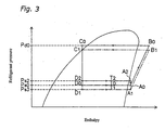
- the gaseous refrigerant is compressed by the compressor 11 from the state at point A0 in Figures 1 and 3 to a prescribed pressure Pd0 (see point B0 in Figures 1 and 3) before being delivered to the outdoor heat exchanger 12.
- Pd0 a prescribed pressure
- the gaseous refrigerant exchanges heat with the outside air and condenses to a liquid refrigerant state (see point C0 in Figures 1 and 3).
- the condensed refrigerant liquid is fed from the outdoor heat exchanger 12 to the expansion valves 13, 14, 15 of the indoor units 3, 4, 5 through the liquid refrigerant pipe 16.
- the liquid refrigerant is delivered from the outdoor heat exchanger 12 to the expansion valves 14, 15 of the indoor units 4, 5 through the liquid refrigerant convergence pipe 16a and the liquid refrigerant branch pipes 16c, 16d and the pressure of the liquid refrigerant is reduced to Ps0 (see point D0 in Figures 1 and 3) by the expansion valves 14, 15.
- the pressure-reduced refrigerant exchanges heat with the air inside each respective room 34, 35 and evaporates, changing to a gaseous refrigerant state (see point A0 in Figures 1 and 3).
- the evaporation temperature of the refrigerant in the indoor heat exchangers 24, 25 is the temperature T0 corresponding to the pressure Ps0.
- This gaseous refrigerant passes through the gaseous refrigerant branch pipes 17c, 17d and converges into the gaseous refrigerant convergence pipe 17a.
- the liquid refrigerant is delivered from the outdoor heat exchanger 12 to the expansion valve 13 of the indoor unit 3 through the liquid refrigerant convergence pipe 16a and the liquid refrigerant branch pipe 16b and the pressure of the liquid refrigerant is reduced to Ps2 (see point D2 in Figures 1 and 3) by the expansion valve 13.
- the pressure-reduced refrigerant exchanges heat with the air inside the room 33 and evaporates, changing to a gaseous refrigerant state (see point A2 in Figures 1 and 3).
- the evaporation temperature of the refrigerant in the indoor heat exchanger 23 is the temperature T2 corresponding to the pressure Ps2.
- the pressure adjusting device 6 since the pressure adjusting device 6 is installed in the gaseous refrigerant branch pipe 17b, the pressure of the refrigerant that evaporated in the indoor heat exchanger 23 is reduced by the electric powered expansion valve 62 of the pressure adjusting device 6 to the same pressure Ps0 as the refrigerant in the other indoor heat exchangers 24, 25 before the refrigerant flows into the gaseous refrigerant convergence pipe 17a.
- the pressure adjusting device 6 detects the evaporation pressure of the indoor heat exchanger 23 of the indoor unit 3 with the pressure detecting means 61 and adjusts the opening of the electric powered expansion valve 62 using the opening adjusting means 63 such that prescribed pressure setting value Ps2 is obtained.
- the gaseous refrigerant is drawn into the compressor 11 through the gaseous refrigerant convergence pipe 17a. In this way, the air inside the rooms 33, 34, 35 is cooled.
- the operation when the outside air temperature is low is basically the same as when the outside air temperature is high.
- the differences between the operation when the outside air temperature is low and the operation when the outside air temperature is high will now be described.
- the intake pressure of the compressor 11 is set to a pressure Ps3 that is lower than the pressure used when the outside temperature is high (pressure Ps0).
- the entire air conditioning system 1 operates at a lower refrigerant temperature.
- the indoor units 4 and 5 of the air conditioning unit 1 operate according to the refrigerant cycle indicated by the single-dot chain lines joining points A1, B1, C1, and D1 in Figure 3 and the indoor unit 3 operates according to the refrigerant cycle indicated by the lines joining points A1, B1, C1, D2, A2, and A1 in Figure 3.
- the intake pressure of the compressor 11 falls from Ps0 to Ps3
- the evaporation temperature of the refrigerant in the indoor heat exchangers 24, 25 of the indoor units 4, 5 falls to a temperature T1 at which there is the possibility that the indoor heat exchangers 24, 25 will freeze.
- the indoor heat exchangers 24, 25 for the rooms 34, 35 freeze, the expansion valves 14, 15 are closed and the indoor units 4, 5 are operated in fan-only mode so that the indoor heat exchangers 24, 25 can be returned from their frozen state to a normal state. Consequently, such temporary inconveniences as a rise in the temperature inside the rooms 34, 35 occur. However, this is not a serious problem because the thermal loads of the rooms 34 and 35 are smaller than the thermal load of the room 33.
- the pressure adjusting device 6 installed downstream of the indoor heat exchanger 23 adjusts the refrigerant pressure Ps2 of the indoor heat exchanger 23 such that the evaporation temperature becomes a temperature T2 (e.g., a temperature approximately equal to the evaporation temperature when the outside air temperature is high) at which freezing of the indoor heat exchanger 23 does not occur.
- a temperature T2 e.g., a temperature approximately equal to the evaporation temperature when the outside air temperature is high
- lubricating oil from the compressor 11 accumulates chiefly in the gaseous refrigerant pipe 17.
- the system is operated in oil recovery mode, i.e., the expansion valves 13, 14, 15 disposed upstream of the indoor heat exchangers 23, 24, 25 are opened fully while running the compressor 11 in order to push the lubrication oil accumulated in the refrigerant circuit toward the inlet of the compressor 11.
- the electric powered expansion valve 62 of the pressure adjusting device 6 can also be opened fully in response to the fuel recovery mode start command from the main control unit 20 of the air conditioning system 1, the lubricating oil accumulated in the refrigerant piping of the indoor unit 3 is recovered in the same manner as the lubricating oil accumulated in the refrigerant piping of the indoor units 4 and 5.
- An air conditioning system pressure adjusting device and air conditioning system equipped with the same in accordance with this embodiment have the following characteristic features.
- a pressure adjusting device 6 in accordance with this embodiment makes it possible to adjust the pressure of the refrigerant in the indoor heat exchanger 23 to a prescribed pressure setting by adjusting the opening of the electric powered expansion valve 62. As a result, the pressure of the refrigerant in the indoor heat exchanger 23 can be adjusted to a higher pressure than the pressure of the refrigerant in the gaseous refrigerant pipe 17 between the electric powered expansion valve 62 and the compressor 11.
- the pressure of the refrigerant in the indoor heat exchanger 23 can be adjusted to a pressure Ps2 that is higher than the pressure Ps3 such that the gaseous refrigerant in the gaseous refrigerant pipe 17 downstream of the electric powered expansion valve 62 is prevented from liquefying and the evaporation temperature of the refrigerant becomes a temperature T2 at which the indoor heat exchanger 23 will not freeze.
- the indoor unit 3 can be run in cooling mode continuously.
- the refrigerant pressure Ps2 of the indoor heat exchanger 23 can be adjusted easily by simply changing the pressure setting value of the opening adjusting means 63 of the pressure adjusting device.
- the indoor unit 3 installed in the room 33 where the thermal load is high can be run in cooling mode continuously even when the outside temperature is low by installing this kind of pressure adjusting device 6 for that indoor unit 3 only.
- a pressure adjusting device 6 in accordance with this embodiment is easy to interlock with a command from the main control unit 20 of the air conditioning system 1 because the electric powered expansion valve 62 is electrically driven.
- the opening adjusting means 63 not only provides the electric powered expansion valve 62 with an opening for adjusting the pressure of the refrigerant in the indoor heat exchanger 23 but can also provide an opening that is appropriate for oil recovery mode when the system is run in oil recovery mode.
- the air conditioning system can be run in an oil recovery mode similar to the oil recovery mode of conventional air conditioning systems.
- the electric powered expansion valve 62 When, for example, the electric powered expansion valve 62 is arranged in the outdoor portion of the gaseous refrigerant pipe 17, the refrigerant in the portion of the gaseous refrigerant pipe 17 upstream of the electric powered expansion valve 62 will be cooled by the outside air and partially liquefy. Then, the partially liquefied refrigerant is reduced in pressure by the electric powered expansion valve 62 and the liquid portion is evaporated again before being drawn into the compressor 11.
- a pressure adjusting device 6 in accordance with this embodiment is a single unit integrating the electric powered expansion valve 62, the pressure detecting means 61, and the opening adjusting means 63, it can be installed easily in, for example, the gaseous refrigerant pipe of an existing air conditioning system in order to prevent freezing of the indoor heat exchanger.
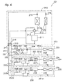
- FIG. 6 is a schematic view of the refrigerant circuit of an air conditioning system 201 in accordance with a second embodiment of the present invention.
- the air conditioning system 201 is provided chiefly with one air-cooled outdoor unit 202 and a plurality of (three in this embodiment) indoor units 203, 204, 205 connected in parallel to the outdoor unit 202. It is used, for example, to air-condition an office or the like.
- the indoor unit 203 is installed in a room that is a server room fitted with server equipment, similarly to the first embodiment.
- the server room has a larger amount of discharged heat than the rooms in which the other indoor units 204, 205 are installed.
- the indoor units 204 and 205 are connected to the outdoor unit 202 in such a manner that they can be switched between cooling mode and heating mode while the indoor unit 203 runs in cooling mode.
- the outdoor unit 202 is constituted such that its operating capacity can be adjusted in accordance with the total operating load resulting from the cooling operation and heating operation of the indoor units 203, 204, 205.
- the outdoor unit 202 is installed outdoors and includes chiefly the following devices and valves, which are connected with refrigerant piping: a compressor 211, an outdoor main heat exchanger 212a, a four-way selector valve 213, an outdoor expansion valve 214, an outdoor auxiliary heat exchanger 212b, an outdoor solenoid valve 216, a liquid refrigerant shut-off valve 217, a first gaseous refrigerant shut-off valve 218, and a second gaseous refrigerant shut-off valve 219.
- the compressor 211 is a device for compressing gaseous refrigerant.
- the intake side of the compressor 211 is connected to the four-way selector valve 213 and the second gaseous refrigerant shut-off valve 219.
- the discharge side of the compressor 211 is connected to the four-way selector valve 213 and the outdoor auxiliary heat exchanger 212b.
- the outdoor main heat exchanger 212a is a heat exchanger for evaporating and condensing the refrigerant using the outside air as a heat source and forms the outdoor heat exchanger 212 together with the outside auxiliary heat exchanger 212b.
- the gas side of the outdoor main heat exchanger 212a is connected to the four-way selector valve 213.
- the liquid side of the outdoor main heat exchanger 212a is connected to the liquid refrigerant shut-off valve 217.
- the outdoor expansion valve 214 is provided between the liquid side of the outdoor main heat exchanger 212a and the liquid refrigerant shut-off valve 217.
- the outdoor expansion valve 214 is an electric powered expansion valve configured such that it can adjust the amount of refrigerant flowing through the outdoor main heat exchanger 212a.
- the four-way selector valve 213 is a selector valve configured to make the outdoor main heat exchanger 212a function as either an evaporator or a condenser.
- the four-way selector valve 213 is connected to the gas side of the outdoor main heat exchanger 212a, the intake side of the compressor 211, the discharge side of the compressor 211, and the first gaseous refrigerant shut-off valve 218.
- the four-way selector valve 213 can connect the discharge side of the compressor 211 to the gas side of the outdoor main heat exchanger 212a and connect the intake side of the compressor 211 to the first gaseous refrigerant shut-off valve 218.
- the four-way selector valve 213 can connect the gas side of the outdoor main heat exchanger 212a to the intake side of the compressor 211 and connect the discharge side of the compressor 211 to the first gaseous refrigerant shut-off valve 218.
- the outdoor auxiliary heat exchanger 212b is connected in parallel with the outdoor main heat exchanger 212a and serves to condense the refrigerant using the outside air as a heat source.
- the outdoor solenoid valve 216 that can be opened and closed when necessary is provided on the liquid side of the outdoor auxiliary heat exchanger 212b. As a result, the overall refrigerant evaporation amount of the outdoor heat exchanger 212 can be adjusted.
- the indoor units 203, 204, 205 are each equipped chiefly with an expansion valve 223, 224, 225 and an indoor heat exchanger 233, 234, 235 and these devices and valves are connected together with refrigerant piping.
- the indoor expansion valves 223, 224, 225 are electric powered expansion valves for reducing the pressure of the liquid refrigerant during operation in cooling mode.
- the indoor heat exchangers 233, 234, 235 function as refrigerant condensers during heating mode and as refrigerant evaporators during cooling mode.
- liquid refrigerant pipe 251, the first gaseous refrigerant pipe 252, and the second gaseous refrigerant pipe 253 are connected to the outdoor unit 202.
- the liquid refrigerant pipe 251 serves to connect the liquid refrigerant shut-off valve 217 of the outdoor unit 202 to the indoor units 203, 204, 205 and includes the following: liquid refrigerant branch pipes 251b, 251c, 251d corresponding to the respective indoor units 203, 204, 205; and a liquid refrigerant convergence pipe 251a into which the liquid refrigerant branch pipes 251b, 251c, 251d converge and which is connected to the liquid refrigerant shut-off valve 217.
- the liquid refrigerant branch pipe 251b is connected to the indoor expansion valve 223 of the indoor unit 203.
- the liquid refrigerant branch pipe 251c runs from its junction with the liquid refrigerant convergence pipe 251a and connects to the indoor expansion valve 224 of the indoor unit 204, passing through the heating/cooling changeover device 207 (discussed later) in-between.
- the liquid refrigerant branch pipe 251d runs from its junction with the liquid refrigerant convergence pipe 251a and connects to the indoor expansion valve 225 of the indoor unit 205, passing through the heating/cooling changeover device 208 (discussed later) in-between.
- the first gaseous refrigerant pipe 252 serves to connect the first gaseous refrigerant shut-off valve 218 of the outdoor unit 202 to the indoor units 204, 205 (i.e., the indoor units other than the indoor unit 203) and includes the following: first gaseous refrigerant branch pipes 252c, 252d corresponding to the respective indoor units 204, 205; and a first gaseous refrigerant convergence pipe 252a into which the first gaseous refrigerant branch pipes 252c, 252d converge and which is connected to the first gaseous refrigerant shut-off valve 218.
- the first gaseous refrigerant branch pipe 252c runs from its junction with the first gaseous refrigerant convergence pipe 252a and connects to the indoor heat exchanger 234 of the indoor unit 204, passing through the heating/cooling changeover device 207 in-between.
- the first gaseous refrigerant branch pipe 252d runs from its junction with the first gaseous refrigerant convergence pipe 252a and connects to the indoor heat exchanger 235 of the indoor unit 205, passing through the heating/cooling changeover device 208 in-between.
- the second gaseous refrigerant pipe 253 serves to connect the second gaseous refrigerant shut-off valve 219 of the outdoor unit 202 to the indoor units 203, 204, 205 and includes the following: second gaseous refrigerant branch pipes 253b, 253c, 253d corresponding to the respective indoor units 203, 204, 205; and a second gaseous refrigerant convergence pipe 253a into which the second gaseous refrigerant branch pipes 253b, 253c, 253d converge and which is connected to the second gaseous refrigerant shut-off valve 219.
- the second gaseous refrigerant branch pipe 253b runs from its junction with the second gaseous refrigerant convergence pipe 253a and connects to the indoor heat exchanger 233 of the indoor unit 203, passing through the pressure adjusting device 206 (discussed later) in-between.
- the second gaseous refrigerant branch pipe 253c runs from its junction with the second gaseous refrigerant convergence pipe 253a and connects to the indoor heat exchanger 234 of the indoor unit 204, passing through the heating/cooling changeover device 207 in-between.
- the second gaseous refrigerant branch pipe 253d runs from its junction with the second gaseous refrigerant convergence pipe 253a and connects to the indoor heat exchanger 235 of the indoor unit 205, passing through the heating/cooling changeover device 208 in-between.
- the pressure adjusting device 206 is a single unit equipped with a pressure detecting means 261, an electric powered expansion valve 262, and an opening adjusting means 263. It is provided in the second gaseous refrigerant branch pipe 253b, which connects the outdoor unit 202 and the indoor unit 203 together.
- the pressure adjusting device 206 can adjust the pressure of the refrigerant in the indoor heat exchanger 233 of the indoor unit 203 to a higher pressure than the refrigerant in the indoor heat exchangers 234, 235 of the other indoor units 204, 205.
- the opening adjusting means 263 of the pressure adjusting device 206 is capable of forcefully providing the electric powered expansion valve 262 with an opening value that is appropriate for oil recovery mode in response to an oil recovery mode signal issued from the main control unit 20 of the air conditioning system 201 when oil recovery mode is executed.
- the indoor units 207, 208 are each equipped chiefly with a subcooling heat exchanger 241, 242, a low-pressure gaseous refrigerant return valve 243, 244, and a high-pressure gaseous refrigerant supply valve 245, 246.
- the heating/cooling changeover devices 207; 208 are configured such that, when the indoor units 204, 205 run in cooling mode, liquid refrigerant can be supplied from the outdoor unit 202 to the indoor units 204, 205 through the liquid refrigerant branch pipes 251c, 251d of the liquid refrigerant pipe 251 and the subcooling heat exchangers 241, 242.
- the heating/cooling changeover devices 207, 208 are further configured such that refrigerant evaporated in the indoor heat exchangers 234, 235 of the indoor units 204, 205 can be delivered to the second gaseous refrigerant branch pipes 253c, 253d of the second gaseous refrigerant pipe 253 through the low-pressure gaseous refrigerant return valves 243, 244.
- the heating/cooling changeover devices 207, 208 are configured such that, when the indoor units 204, 205 run in heating mode, gaseous refrigerant can be supplied from the outdoor unit 202 to the indoor units 204, 205 through the first gaseous refrigerant branch pipes 252c, 252d of the first gaseous refrigerant pipe 252 and the high-pressure gaseous refrigerant supply valves 245, 246.
- the heating/cooling changeover devices 207, 208 are further configured such that refrigerant condensed in the indoor heat exchangers 234, 235 of the indoor units 204, 205 can be delivered to the liquid refrigerant branch pipes 251c, 251d of the liquid refrigerant pipe 251 through the subcooling heat exchangers 241, 242.
- the subcooling heat exchangers 241, 242 serve to subcool the liquid refrigerant supplied to the indoor units 204, 205 from the outdoor unit 202. More specifically, the heating/cooling changeover devices 207, 208 each have a subcooling valve 247, 248 and a capillary 249, 250 for reducing the pressure of a portion of the liquid refrigerant that is supplied to the heating/cooling changeover devices 207, 208 from the liquid refrigerant branch pipes 251c, 251d during cooling mode.
- the subcooling heat exchangers 241, 242 cool the liquid refrigerant heading toward the indoor units 204, 205 to a subcooled state using this pressure-reduced refrigerant as a cooling source.
- the refrigerant used as a cooling source is evaporated in the subcooling heat exchangers 241, 242, it is returned downstream of the low-pressure gaseous refrigerant return valves 243, 244 and converges with the refrigerant evaporated in the indoor units 204, 205.
- the indoor unit 203 differs from the indoor units 204, 205 in that it is a dedicated cooling unit connected to a pressure adjusting device 206 instead of a heating/cooling changeover device 207, 208.
- the air conditioning system 201 is configured such that it can perform simultaneous heating and cooling.
- the indoor unit 203 installed in a server room can be run in cooling mode while the indoor units 204, 205 are run in heating mode or the indoor unit 203 and the indoor unit 204 can be run in cooling mode while the indoor unit 205 is run in heating mode.
- the refrigerant circuit of the air conditioning system 201 is configured as shown in Figure 7 (the flow of the refrigerant is indicated by arrows in the figure).
- the outdoor unit 202 is configured such that, when the operating load for heating is larger than the operating load for cooling, the outdoor main heat exchanger 212a can be made to operate as an evaporator by switching the four-way selector valve 213 to the heating position (broken line in Figure 7) and the outdoor auxiliary heat exchanger 212b can be made to operate as a condenser by opening the outdoor solenoid valve 216 in accordance with the heating operating load.
- the gaseous refrigerant compressed by the compressor 211 is fed to the indoor units 204, 205 through the four-way selector valve 213, the first gaseous refrigerant shut-off valve 218 and the first gaseous refrigerant pipe 252.
- the gaseous refrigerant fed to the indoor units 204, 205 is directed through the high-pressure gaseous refrigerant supply valves 245, 246 of the heating/cooling changeover devices 207, 208 and into the indoor heat exchangers 234, 235 of the indoor units 204, 205, where it condenses and heats the air in the respective rooms. Then, the condensed refrigerant passes through the indoor expansion valves 224, 225 and the subcooling heat exchangers 241, 242 of the heating/cooling changeover devices 207, 208 and into the liquid refrigerant pipe 251.
- the condensed refrigerant passes through the liquid refrigerant convergence pipe 251 a and returns to the outdoor unit 202.
- the portion of the gaseous refrigerant compressed by the compressor 211 that is directed to the outdoor auxiliary heat exchanger 212b is condensed.
- This condensed refrigerant is mixed with the refrigerant returning from the indoor units 204, 205 through the liquid refrigerant pipe 251, reduced in pressure by the outdoor expansion valve 214, and directed into the outdoor main heat exchanger 212a, where it is evaporated. Then, the evaporated refrigerant is drawn into the compressor 211 again through the four-way selector valve 213.
- the flow rate of the gaseous refrigerant supplied from the outdoor unit 202 to the indoor units 204, 205 through the first gaseous refrigerant pipe 252 is adjusted by the condensation of refrigerant performed by the outdoor auxiliary heat exchanger 212b and the flow rate adjustment executed by the outdoor expansion valve 214.
- the portion of refrigerant condensed in the indoor units 204, 205 is directed to the indoor unit 203 through the liquid refrigerant branch pipe 251b. Then, after the refrigerant is reduced in pressure by the indoor expansion valves 223, it is evaporated in the indoor heat exchanger 233 and cools the air inside the server room before being fed to the pressure adjusting device 206.
- the pressure adjusting device 206 adjusts the refrigerant pressure in the indoor heat exchanger 233 (corresponds to Ps2 in Figure 3) so as to achieve an evaporation temperature (corresponds to T2 in Figure 3) at which the indoor heat exchanger 233 does not freeze. After having its pressure reduced by the pressure adjusting device 206, the refrigerant is returned to the intake side of the compressor 211 of the outdoor 202 unit through the second gaseous refrigerant pipe 253.
- the refrigerant pressure inside the indoor heat exchanger 233 would become too low and the possibility of the indoor heat exchanger 233 freezing would be high. Furthermore, if the system were operated at a refrigerant pressure at which the indoor heat exchanger 233 does not freeze, the influence of the gaseous refrigerant returned to the outdoor unit 202 through the second gaseous refrigerant pipe 253 from the indoor unit 203 would become large and it would be possible for the gaseous refrigerant to liquefy on the intake side of the compressor 211.
- the indoor unit 203 can be run continuously in cooling mode because the gaseous refrigerant in the second the gaseous refrigerant pipe 253 is prevented from liquefying and the indoor heat exchanger 233 is prevented from freezing.
- the present invention when the present invention is applied to an air conditioning system 201 that is capable of simultaneous heating and cooling, the same effects as the first embodiment can be obtained. Even when the outside air temperature is low, the room (e.g., a server room) having a large thermal load can be cooled continuously while performing simultaneous heating and cooling.
- the room e.g., a server room
- the refrigerant pressure in the indoor heat exchanger can be adjusted to a higher pressure than the refrigerant pressure in the gaseous refrigerant pipe between the electric powered expansion valve and the compressor. Therefore, even when the outside air temperature is low, the refrigerant pressure in the gaseous refrigerant pipe downstream of the electric powered expansion valve can be lowered so as to prevent the gaseous refrigerant from liquefying and the refrigerant pressure in the indoor heat exchanger can be adjusted such that the evaporation temperature of the refrigerant is a temperature at which the indoor heat exchanger will not freeze, thus preventing the indoor heat exchanger from freezing. As a result, continuous operation in cooling mode can be accomplished even when the outside air temperature is low.
Landscapes
- Engineering & Computer Science (AREA)
- Mechanical Engineering (AREA)
- General Engineering & Computer Science (AREA)
- Physics & Mathematics (AREA)
- Thermal Sciences (AREA)
- Chemical & Material Sciences (AREA)
- Combustion & Propulsion (AREA)
- Air Conditioning Control Device (AREA)
- Compression-Type Refrigeration Machines With Reversible Cycles (AREA)
Abstract
Description
Claims (6)
- A pressure adjusting device (6, 206) for adjusting the pressure in the indoor heat exchanger (23, 233) of an air conditioning system (1, 201) equipped with an outdoor unit (2, 202) having a compressor (11, 211) and an outdoor heat exchanger (12, 212), an indoor unit (3, 203) having an indoor heat exchanger (23, 233), and a gaseous refrigerant pipe (17, 253) connecting the indoor heat exchanger (23, 233) to the compressor (11, 211), the pressure adjusting device (6, 206) being provided with the following:a pressure detecting means (61, 261) for detecting the pressure value of the refrigerant in the indoor heat exchanger (23, 233);an electric powered expansion valve (62, 262) installed in the gaseous refrigerant pipe (17, 253); andan opening adjusting means (63, 263) that adjusts the opening of the electric powered expansion valve (62, 262) based on the pressure value of the refrigerant detected by the pressure detecting means (61, 261) such that the pressure value of the refrigerant is adjusted to a prescribed pressure setting value.
- An air conditioning system pressure adjusting device (6, 206) as recited in claim 1, wherein the opening adjusting means (63, 263) is capable of providing the electric powered expansion valve (62, 262) with an opening value that is appropriate for oil recovery mode when the air conditioning system runs in oil recovery mode in order to return lubricating oil that has accumulated in the refrigerant circuit to the compressor (11, 211).
- An air conditioning system pressure adjusting device (6, 206) as recited in claim 1 or 2, wherein the electric powered expansion valve (62, 262) is installed in the indoor portion of the gaseous refrigerant pipe (17, 253).
- An air conditioning system pressure adjusting device (6, 206) as recited in any one of claims 1 to 3, wherein the electric powered expansion valve (62, 262), the pressure detecting means (61, 261), and opening adjusting means (63, 263) are constructed as a single integral unit.
- An air conditioning system (1, 201) equipped with the following:an outdoor unit (2, 202) having a compressor (11, 211) and an outdoor heat exchanger (12, 212);a plurality of indoor units (3 to 5, 203 to 205) each having an indoor heat exchanger (23 to 25, 233 to 235);a gaseous refrigerant pipe (17, 253) having a plurality of gaseous refrigerant branch pipes (17b to 17d, 253b to 253d) connected to the indoor heat exchangers (23 to 25, 233 to 235) of the respective indoor units (3 to 5, 203 to 205) and a gaseous refrigerant convergence pipe (17a, 253a) into which the gaseous refrigerant branch pipes (17b to 17d, 253b to 253d) converge and which is connected to the compressor (11, 211); anda pressure adjusting device (6, 206) as recited in any one of claims 1 to 4 connected to some of the gaseous refrigerant branch pipes (17b, 253b).
- An air conditioning system (201) as recited in claim 5, whereinthe indoor units (204, 205) corresponding to the gaseous refrigerant branch pipes (253c, 253d) that do not have a pressure adjusting device (206) connected thereto are connected to the outdoor unit (202) in such a manner that they can switch between cooling mode and heating mode; andthe operating capacity of the outdoor unit (202) can be adjusted in accordance with the total operating load resulting from the cooling operation and heating operation of the plurality of indoor units (203 to 205).
Applications Claiming Priority (3)
| Application Number | Priority Date | Filing Date | Title |
|---|---|---|---|
| JP2002074378 | 2002-03-18 | ||
| JP2002074378 | 2002-03-18 | ||
| PCT/JP2003/002814 WO2003078903A1 (en) | 2002-03-18 | 2003-03-10 | Pressure control device of air conditioner and air conditioner having the device |
Publications (3)
| Publication Number | Publication Date |
|---|---|
| EP1486740A1 true EP1486740A1 (en) | 2004-12-15 |
| EP1486740A4 EP1486740A4 (en) | 2012-09-05 |
| EP1486740B1 EP1486740B1 (en) | 2013-11-06 |
Family
ID=28035300
Family Applications (1)
| Application Number | Title | Priority Date | Filing Date |
|---|---|---|---|
| EP03708530.5A Expired - Lifetime EP1486740B1 (en) | 2002-03-18 | 2003-03-10 | Air conditioning system |
Country Status (8)
| Country | Link |
|---|---|
| US (1) | US6990822B2 (en) |
| EP (1) | EP1486740B1 (en) |
| JP (1) | JP3940844B2 (en) |
| KR (1) | KR100550316B1 (en) |
| CN (1) | CN1224810C (en) |
| AU (1) | AU2003213443B2 (en) |
| ES (1) | ES2443644T3 (en) |
| WO (1) | WO2003078903A1 (en) |
Families Citing this family (26)
| Publication number | Priority date | Publication date | Assignee | Title |
|---|---|---|---|---|
| US7219505B2 (en) * | 2004-10-22 | 2007-05-22 | York International Corporation | Control stability system for moist air dehumidification units and method of operation |
| KR100733295B1 (en) * | 2004-12-28 | 2007-06-28 | 엘지전자 주식회사 | Subcooling device of air conditioner |
| JP4624223B2 (en) * | 2005-09-20 | 2011-02-02 | 三洋電機株式会社 | Refrigeration system |
| DE102006052321A1 (en) * | 2005-11-24 | 2007-06-06 | Danfoss A/S | Method of analyzing a refrigeration system and method of controlling a refrigeration system |
| JP4766256B2 (en) | 2006-07-24 | 2011-09-07 | 株式会社富士通ゼネラル | Control method of air conditioner |
| JP5055965B2 (en) * | 2006-11-13 | 2012-10-24 | ダイキン工業株式会社 | Air conditioner |
| KR100854829B1 (en) | 2007-02-13 | 2008-08-27 | 엘지전자 주식회사 | Air Conditioning System and Its Control Method |
| WO2008146709A1 (en) * | 2007-05-25 | 2008-12-04 | Mitsubishi Electric Corporation | Refrigeration cycle device |
| KR100953193B1 (en) * | 2007-12-21 | 2010-04-15 | 엘지전자 주식회사 | Operation method of multi type air conditioner |
| CN102449411B (en) * | 2009-05-29 | 2014-01-29 | 三菱电机株式会社 | Refrigeration cycle device and air-conditioning device |
| CN102753910B (en) * | 2010-02-10 | 2015-09-30 | 三菱电机株式会社 | Refrigeration cycle device |
| JP5312681B2 (en) * | 2010-03-25 | 2013-10-09 | 三菱電機株式会社 | Air conditioner |
| US9322581B2 (en) | 2011-02-11 | 2016-04-26 | Johnson Controls Technology Company | HVAC unit with hot gas reheat |
| TWI468628B (en) * | 2011-11-21 | 2015-01-11 | Ind Tech Res Inst | Easy pipe arranging device, air conditioning equipment using the same and refrigerant leakage detecting method thereof |
| CN102654303A (en) * | 2012-05-09 | 2012-09-05 | 青岛海尔空调电子有限公司 | Air conditioning system and pressure adjusting method and device for same |
| JP6052488B2 (en) * | 2012-07-09 | 2016-12-27 | 株式会社富士通ゼネラル | Air conditioner |
| WO2014118945A1 (en) * | 2013-01-31 | 2014-08-07 | 日立アプライアンス株式会社 | Refrigeration cycle device |
| WO2017163339A1 (en) * | 2016-03-23 | 2017-09-28 | 三菱電機株式会社 | Air-conditioning device |
| CN106996596B (en) * | 2017-04-18 | 2023-09-19 | 珠海格力电器股份有限公司 | Air conditioning system and waste heat recovery method thereof |
| CN107575939B (en) * | 2017-09-07 | 2019-10-25 | 珠海格力电器股份有限公司 | Multi-split system and control method thereof |
| CN108731187B (en) * | 2018-06-20 | 2020-05-08 | 广东美的暖通设备有限公司 | Three-pipe heat recovery multi-split air conditioner system and control method thereof |
| US11629866B2 (en) | 2019-01-02 | 2023-04-18 | Johnson Controls Tyco IP Holdings LLP | Systems and methods for delayed fluid recovery |
| JP7243313B2 (en) * | 2019-03-12 | 2023-03-22 | 株式会社富士通ゼネラル | air conditioner |
| WO2021050468A1 (en) * | 2019-09-13 | 2021-03-18 | Carrier Corporation | Hvac unit with expansion device |
| CN112594871B (en) * | 2020-12-31 | 2022-02-08 | 广东积微科技有限公司 | Defrosting control method of multifunctional multi-split system with double four-way valves |
| CN116518579B (en) * | 2023-05-09 | 2025-09-26 | 广东开利暖通空调股份有限公司 | Control method of air conditioning system |
Family Cites Families (14)
| Publication number | Priority date | Publication date | Assignee | Title |
|---|---|---|---|---|
| US3702066A (en) * | 1971-07-22 | 1972-11-07 | Gen Motors Corp | Automatic expansion valve, in line, piloted |
| US3998570A (en) * | 1975-04-23 | 1976-12-21 | General Motors Corporation | Air conditioning compressor |
| US3965693A (en) * | 1975-05-02 | 1976-06-29 | General Motors Corporation | Modulated throttling valve |
| US4084388A (en) * | 1976-11-08 | 1978-04-18 | Honeywell Inc. | Refrigeration control system for optimum demand operation |
| US4184341A (en) * | 1978-04-03 | 1980-01-22 | Pet Incorporated | Suction pressure control system |
| US4442680A (en) * | 1980-10-31 | 1984-04-17 | Sporlan Valve Company | Pilot-operated pressure regulator valve |
| US4589263A (en) * | 1984-04-12 | 1986-05-20 | Hussmann Corporation | Multiple compressor oil system |
| US4621505A (en) * | 1985-08-01 | 1986-11-11 | Hussmann Corporation | Flow-through surge receiver |
| DE3824235C1 (en) * | 1988-07-16 | 1989-10-26 | Danfoss A/S, Nordborg, Dk | |
| KR920008504B1 (en) * | 1988-10-17 | 1992-09-30 | 미쓰비시전기주식회사 | Air conditioner |
| JP2910260B2 (en) | 1991-02-07 | 1999-06-23 | ダイキン工業株式会社 | Air conditioner and operation controller of air conditioner |
| US5388419A (en) * | 1993-04-23 | 1995-02-14 | Maritime Geothermal Ltd. | Staged cooling direct expansion geothermal heat pump |
| JP3329603B2 (en) * | 1994-12-14 | 2002-09-30 | 東芝キヤリア株式会社 | Air conditioner |
| WO2002001122A1 (en) * | 2000-06-28 | 2002-01-03 | Igc Polycold Systems, Inc. | High efficiency very-low temperature mixed refrigerant system with rapid cool down |
-
2003
- 2003-03-10 AU AU2003213443A patent/AU2003213443B2/en not_active Ceased
- 2003-03-10 JP JP2003576871A patent/JP3940844B2/en not_active Expired - Fee Related
- 2003-03-10 WO PCT/JP2003/002814 patent/WO2003078903A1/en not_active Ceased
- 2003-03-10 KR KR1020037015048A patent/KR100550316B1/en not_active Expired - Fee Related
- 2003-03-10 CN CNB038002884A patent/CN1224810C/en not_active Expired - Fee Related
- 2003-03-10 ES ES03708530.5T patent/ES2443644T3/en not_active Expired - Lifetime
- 2003-03-10 US US10/479,854 patent/US6990822B2/en not_active Expired - Lifetime
- 2003-03-10 EP EP03708530.5A patent/EP1486740B1/en not_active Expired - Lifetime
Also Published As
| Publication number | Publication date |
|---|---|
| AU2003213443A1 (en) | 2003-09-29 |
| KR20040023601A (en) | 2004-03-18 |
| AU2003213443B2 (en) | 2005-05-05 |
| JPWO2003078903A1 (en) | 2005-07-14 |
| EP1486740A4 (en) | 2012-09-05 |
| EP1486740B1 (en) | 2013-11-06 |
| ES2443644T3 (en) | 2014-02-20 |
| JP3940844B2 (en) | 2007-07-04 |
| CN1509395A (en) | 2004-06-30 |
| KR100550316B1 (en) | 2006-02-07 |
| CN1224810C (en) | 2005-10-26 |
| WO2003078903A1 (en) | 2003-09-25 |
| US6990822B2 (en) | 2006-01-31 |
| US20040144111A1 (en) | 2004-07-29 |
Similar Documents
| Publication | Publication Date | Title |
|---|---|---|
| EP1486740B1 (en) | Air conditioning system | |
| US7360372B2 (en) | Refrigeration system | |
| US10006647B2 (en) | Air conditioning system with distributor for a plurality of indoor units | |
| KR101726073B1 (en) | Air conditioning system | |
| KR100833441B1 (en) | Freezer | |
| KR20040037086A (en) | Refrigeration equipment | |
| US10393418B2 (en) | Air-conditioning apparatus | |
| JP2009109065A (en) | Refrigeration equipment | |
| WO2013179334A1 (en) | Air conditioning device | |
| US20200240682A1 (en) | Air conditioner | |
| KR20070001078A (en) | Freezer | |
| US20060090487A1 (en) | Air conditioner | |
| KR20070007771A (en) | Freezer | |
| JP2010276239A (en) | Refrigeration air conditioner | |
| JPWO2011074028A1 (en) | Air conditioner | |
| WO2016189739A1 (en) | Air conditioning device | |
| JP2944507B2 (en) | Air conditioner | |
| JP5149663B2 (en) | Engine driven heat pump | |
| US12595941B2 (en) | Heat pump system and control method thereof | |
| KR20150074639A (en) | An air conditioning system and a method for controlling the same | |
| JP4244900B2 (en) | Refrigeration equipment | |
| KR20150000158A (en) | A combined refrigerating and air conditioning system | |
| EP2208007B1 (en) | Refrigerating system and method for operating the same | |
| JPH06180164A (en) | Air-conditioner | |
| KR20190126553A (en) | Cooling system for a low temperature storage |
Legal Events
| Date | Code | Title | Description |
|---|---|---|---|
| PUAI | Public reference made under article 153(3) epc to a published international application that has entered the european phase |
Free format text: ORIGINAL CODE: 0009012 |
|
| 17P | Request for examination filed |
Effective date: 20031125 |
|
| AK | Designated contracting states |
Kind code of ref document: A1 Designated state(s): AT BE BG CH CY CZ DE DK EE ES FI FR GB GR HU IE IT LI LU MC NL PT RO SE SI SK TR |
|
| AX | Request for extension of the european patent |
Extension state: AL LT LV MK |
|
| REG | Reference to a national code |
Ref country code: DE Ref legal event code: R079 Ref document number: 60345217 Country of ref document: DE Free format text: PREVIOUS MAIN CLASS: F24F0011020000 Ipc: F25B0013000000 |
|
| A4 | Supplementary search report drawn up and despatched |
Effective date: 20120806 |
|
| RIC1 | Information provided on ipc code assigned before grant |
Ipc: F25B 47/00 20060101ALI20120731BHEP Ipc: F25B 41/04 20060101ALI20120731BHEP Ipc: F25B 13/00 20060101AFI20120731BHEP |
|
| 17Q | First examination report despatched |
Effective date: 20121106 |
|
| GRAP | Despatch of communication of intention to grant a patent |
Free format text: ORIGINAL CODE: EPIDOSNIGR1 |
|
| INTG | Intention to grant announced |
Effective date: 20130527 |
|
| GRAS | Grant fee paid |
Free format text: ORIGINAL CODE: EPIDOSNIGR3 |
|
| GRAA | (expected) grant |
Free format text: ORIGINAL CODE: 0009210 |
|
| RIN1 | Information on inventor provided before grant (corrected) |
Inventor name: MATSUOKA, HIROMUNE |
|
| AK | Designated contracting states |
Kind code of ref document: B1 Designated state(s): AT BE BG CH CY CZ DE DK EE ES FI FR GB GR HU IE IT LI LU MC NL PT RO SE SI SK TR |
|
| REG | Reference to a national code |
Ref country code: GB Ref legal event code: FG4D |
|
| REG | Reference to a national code |
Ref country code: CH Ref legal event code: EP |
|
| REG | Reference to a national code |
Ref country code: AT Ref legal event code: REF Ref document number: 639768 Country of ref document: AT Kind code of ref document: T Effective date: 20131215 |
|
| REG | Reference to a national code |
Ref country code: IE Ref legal event code: FG4D |
|
| REG | Reference to a national code |
Ref country code: DE Ref legal event code: R096 Ref document number: 60345217 Country of ref document: DE Effective date: 20140102 |
|
| REG | Reference to a national code |
Ref country code: ES Ref legal event code: FG2A Ref document number: 2443644 Country of ref document: ES Kind code of ref document: T3 Effective date: 20140220 |
|
| REG | Reference to a national code |
Ref country code: NL Ref legal event code: VDEP Effective date: 20131106 |
|
| REG | Reference to a national code |
Ref country code: AT Ref legal event code: MK05 Ref document number: 639768 Country of ref document: AT Kind code of ref document: T Effective date: 20131106 |
|
| PG25 | Lapsed in a contracting state [announced via postgrant information from national office to epo] |
Ref country code: SE Free format text: LAPSE BECAUSE OF FAILURE TO SUBMIT A TRANSLATION OF THE DESCRIPTION OR TO PAY THE FEE WITHIN THE PRESCRIBED TIME-LIMIT Effective date: 20131106 Ref country code: FI Free format text: LAPSE BECAUSE OF FAILURE TO SUBMIT A TRANSLATION OF THE DESCRIPTION OR TO PAY THE FEE WITHIN THE PRESCRIBED TIME-LIMIT Effective date: 20131106 Ref country code: NL Free format text: LAPSE BECAUSE OF FAILURE TO SUBMIT A TRANSLATION OF THE DESCRIPTION OR TO PAY THE FEE WITHIN THE PRESCRIBED TIME-LIMIT Effective date: 20131106 |
|
| PG25 | Lapsed in a contracting state [announced via postgrant information from national office to epo] |
Ref country code: AT Free format text: LAPSE BECAUSE OF FAILURE TO SUBMIT A TRANSLATION OF THE DESCRIPTION OR TO PAY THE FEE WITHIN THE PRESCRIBED TIME-LIMIT Effective date: 20131106 Ref country code: BE Free format text: LAPSE BECAUSE OF FAILURE TO SUBMIT A TRANSLATION OF THE DESCRIPTION OR TO PAY THE FEE WITHIN THE PRESCRIBED TIME-LIMIT Effective date: 20131106 |
|
| PG25 | Lapsed in a contracting state [announced via postgrant information from national office to epo] |
Ref country code: PT Free format text: LAPSE BECAUSE OF FAILURE TO SUBMIT A TRANSLATION OF THE DESCRIPTION OR TO PAY THE FEE WITHIN THE PRESCRIBED TIME-LIMIT Effective date: 20140306 |
|
| PG25 | Lapsed in a contracting state [announced via postgrant information from national office to epo] |
Ref country code: EE Free format text: LAPSE BECAUSE OF FAILURE TO SUBMIT A TRANSLATION OF THE DESCRIPTION OR TO PAY THE FEE WITHIN THE PRESCRIBED TIME-LIMIT Effective date: 20131106 |
|
| REG | Reference to a national code |
Ref country code: DE Ref legal event code: R097 Ref document number: 60345217 Country of ref document: DE |
|
| PG25 | Lapsed in a contracting state [announced via postgrant information from national office to epo] |
Ref country code: RO Free format text: LAPSE BECAUSE OF FAILURE TO SUBMIT A TRANSLATION OF THE DESCRIPTION OR TO PAY THE FEE WITHIN THE PRESCRIBED TIME-LIMIT Effective date: 20131106 Ref country code: CZ Free format text: LAPSE BECAUSE OF FAILURE TO SUBMIT A TRANSLATION OF THE DESCRIPTION OR TO PAY THE FEE WITHIN THE PRESCRIBED TIME-LIMIT Effective date: 20131106 Ref country code: SK Free format text: LAPSE BECAUSE OF FAILURE TO SUBMIT A TRANSLATION OF THE DESCRIPTION OR TO PAY THE FEE WITHIN THE PRESCRIBED TIME-LIMIT Effective date: 20131106 |
|
| PLBE | No opposition filed within time limit |
Free format text: ORIGINAL CODE: 0009261 |
|
| STAA | Information on the status of an ep patent application or granted ep patent |
Free format text: STATUS: NO OPPOSITION FILED WITHIN TIME LIMIT |
|
| PG25 | Lapsed in a contracting state [announced via postgrant information from national office to epo] |
Ref country code: DK Free format text: LAPSE BECAUSE OF FAILURE TO SUBMIT A TRANSLATION OF THE DESCRIPTION OR TO PAY THE FEE WITHIN THE PRESCRIBED TIME-LIMIT Effective date: 20131106 |
|
| 26N | No opposition filed |
Effective date: 20140807 |
|
| PG25 | Lapsed in a contracting state [announced via postgrant information from national office to epo] |
Ref country code: LU Free format text: LAPSE BECAUSE OF FAILURE TO SUBMIT A TRANSLATION OF THE DESCRIPTION OR TO PAY THE FEE WITHIN THE PRESCRIBED TIME-LIMIT Effective date: 20140310 |
|
| REG | Reference to a national code |
Ref country code: CH Ref legal event code: PL |
|
| REG | Reference to a national code |
Ref country code: DE Ref legal event code: R097 Ref document number: 60345217 Country of ref document: DE Effective date: 20140807 |
|
| REG | Reference to a national code |
Ref country code: IE Ref legal event code: MM4A |
|
| PG25 | Lapsed in a contracting state [announced via postgrant information from national office to epo] |
Ref country code: CH Free format text: LAPSE BECAUSE OF NON-PAYMENT OF DUE FEES Effective date: 20140331 Ref country code: IE Free format text: LAPSE BECAUSE OF NON-PAYMENT OF DUE FEES Effective date: 20140310 Ref country code: LI Free format text: LAPSE BECAUSE OF NON-PAYMENT OF DUE FEES Effective date: 20140331 |
|
| PG25 | Lapsed in a contracting state [announced via postgrant information from national office to epo] |
Ref country code: SI Free format text: LAPSE BECAUSE OF FAILURE TO SUBMIT A TRANSLATION OF THE DESCRIPTION OR TO PAY THE FEE WITHIN THE PRESCRIBED TIME-LIMIT Effective date: 20131106 |
|
| REG | Reference to a national code |
Ref country code: FR Ref legal event code: PLFP Year of fee payment: 14 |
|
| PG25 | Lapsed in a contracting state [announced via postgrant information from national office to epo] |
Ref country code: BG Free format text: LAPSE BECAUSE OF FAILURE TO SUBMIT A TRANSLATION OF THE DESCRIPTION OR TO PAY THE FEE WITHIN THE PRESCRIBED TIME-LIMIT Effective date: 20131106 Ref country code: MC Free format text: LAPSE BECAUSE OF FAILURE TO SUBMIT A TRANSLATION OF THE DESCRIPTION OR TO PAY THE FEE WITHIN THE PRESCRIBED TIME-LIMIT Effective date: 20131106 |
|
| PG25 | Lapsed in a contracting state [announced via postgrant information from national office to epo] |
Ref country code: CY Free format text: LAPSE BECAUSE OF FAILURE TO SUBMIT A TRANSLATION OF THE DESCRIPTION OR TO PAY THE FEE WITHIN THE PRESCRIBED TIME-LIMIT Effective date: 20131106 Ref country code: GR Free format text: LAPSE BECAUSE OF FAILURE TO SUBMIT A TRANSLATION OF THE DESCRIPTION OR TO PAY THE FEE WITHIN THE PRESCRIBED TIME-LIMIT Effective date: 20140207 |
|
| PG25 | Lapsed in a contracting state [announced via postgrant information from national office to epo] |
Ref country code: HU Free format text: LAPSE BECAUSE OF FAILURE TO SUBMIT A TRANSLATION OF THE DESCRIPTION OR TO PAY THE FEE WITHIN THE PRESCRIBED TIME-LIMIT; INVALID AB INITIO Effective date: 20030310 Ref country code: TR Free format text: LAPSE BECAUSE OF FAILURE TO SUBMIT A TRANSLATION OF THE DESCRIPTION OR TO PAY THE FEE WITHIN THE PRESCRIBED TIME-LIMIT Effective date: 20131106 |
|
| REG | Reference to a national code |
Ref country code: FR Ref legal event code: PLFP Year of fee payment: 15 |
|
| PGFP | Annual fee paid to national office [announced via postgrant information from national office to epo] |
Ref country code: DE Payment date: 20170307 Year of fee payment: 15 Ref country code: FR Payment date: 20170213 Year of fee payment: 15 |
|
| PGFP | Annual fee paid to national office [announced via postgrant information from national office to epo] |
Ref country code: GB Payment date: 20170308 Year of fee payment: 15 |
|
| PGFP | Annual fee paid to national office [announced via postgrant information from national office to epo] |
Ref country code: IT Payment date: 20170320 Year of fee payment: 15 Ref country code: ES Payment date: 20170214 Year of fee payment: 15 |
|
| REG | Reference to a national code |
Ref country code: DE Ref legal event code: R119 Ref document number: 60345217 Country of ref document: DE |
|
| GBPC | Gb: european patent ceased through non-payment of renewal fee |
Effective date: 20180310 |
|
| PG25 | Lapsed in a contracting state [announced via postgrant information from national office to epo] |
Ref country code: DE Free format text: LAPSE BECAUSE OF NON-PAYMENT OF DUE FEES Effective date: 20181002 |
|
| PG25 | Lapsed in a contracting state [announced via postgrant information from national office to epo] |
Ref country code: IT Free format text: LAPSE BECAUSE OF NON-PAYMENT OF DUE FEES Effective date: 20180310 Ref country code: GB Free format text: LAPSE BECAUSE OF NON-PAYMENT OF DUE FEES Effective date: 20180310 |
|
| PG25 | Lapsed in a contracting state [announced via postgrant information from national office to epo] |
Ref country code: FR Free format text: LAPSE BECAUSE OF NON-PAYMENT OF DUE FEES Effective date: 20180331 |
|
| REG | Reference to a national code |
Ref country code: ES Ref legal event code: FD2A Effective date: 20190904 |
|
| PG25 | Lapsed in a contracting state [announced via postgrant information from national office to epo] |
Ref country code: ES Free format text: LAPSE BECAUSE OF NON-PAYMENT OF DUE FEES Effective date: 20180311 |