EP1486738A1 - Electric insulating device of air conditioner, and air conditioner with the device - Google Patents
Electric insulating device of air conditioner, and air conditioner with the device Download PDFInfo
- Publication number
- EP1486738A1 EP1486738A1 EP03708532A EP03708532A EP1486738A1 EP 1486738 A1 EP1486738 A1 EP 1486738A1 EP 03708532 A EP03708532 A EP 03708532A EP 03708532 A EP03708532 A EP 03708532A EP 1486738 A1 EP1486738 A1 EP 1486738A1
- Authority
- EP
- European Patent Office
- Prior art keywords
- refrigerant
- connection
- line
- indoor unit
- outdoor unit
- Prior art date
- Legal status (The legal status is an assumption and is not a legal conclusion. Google has not performed a legal analysis and makes no representation as to the accuracy of the status listed.)
- Withdrawn
Links
Images
Classifications
-
- F—MECHANICAL ENGINEERING; LIGHTING; HEATING; WEAPONS; BLASTING
- F24—HEATING; RANGES; VENTILATING
- F24F—AIR-CONDITIONING; AIR-HUMIDIFICATION; VENTILATION; USE OF AIR CURRENTS FOR SCREENING
- F24F1/00—Room units for air-conditioning, e.g. separate or self-contained units or units receiving primary air from a central station
- F24F1/06—Separate outdoor units, e.g. outdoor unit to be linked to a separate room comprising a compressor and a heat exchanger
- F24F1/26—Refrigerant piping
- F24F1/32—Refrigerant piping for connecting the separate outdoor units to indoor units
-
- F—MECHANICAL ENGINEERING; LIGHTING; HEATING; WEAPONS; BLASTING
- F16—ENGINEERING ELEMENTS AND UNITS; GENERAL MEASURES FOR PRODUCING AND MAINTAINING EFFECTIVE FUNCTIONING OF MACHINES OR INSTALLATIONS; THERMAL INSULATION IN GENERAL
- F16L—PIPES; JOINTS OR FITTINGS FOR PIPES; SUPPORTS FOR PIPES, CABLES OR PROTECTIVE TUBING; MEANS FOR THERMAL INSULATION IN GENERAL
- F16L23/00—Flanged joints
- F16L23/16—Flanged joints characterised by the sealing means
- F16L23/167—Flanged joints characterised by the sealing means in connection with the appearance or detection of leaks
-
- F—MECHANICAL ENGINEERING; LIGHTING; HEATING; WEAPONS; BLASTING
- F16—ENGINEERING ELEMENTS AND UNITS; GENERAL MEASURES FOR PRODUCING AND MAINTAINING EFFECTIVE FUNCTIONING OF MACHINES OR INSTALLATIONS; THERMAL INSULATION IN GENERAL
- F16L—PIPES; JOINTS OR FITTINGS FOR PIPES; SUPPORTS FOR PIPES, CABLES OR PROTECTIVE TUBING; MEANS FOR THERMAL INSULATION IN GENERAL
- F16L25/00—Construction or details of pipe joints not provided for in, or of interest apart from, groups F16L13/00 - F16L23/00
- F16L25/02—Construction or details of pipe joints not provided for in, or of interest apart from, groups F16L13/00 - F16L23/00 specially adapted for electrically insulating the two pipe ends of the joint from each other
- F16L25/026—Construction or details of pipe joints not provided for in, or of interest apart from, groups F16L13/00 - F16L23/00 specially adapted for electrically insulating the two pipe ends of the joint from each other for flanged joints
-
- F—MECHANICAL ENGINEERING; LIGHTING; HEATING; WEAPONS; BLASTING
- F24—HEATING; RANGES; VENTILATING
- F24F—AIR-CONDITIONING; AIR-HUMIDIFICATION; VENTILATION; USE OF AIR CURRENTS FOR SCREENING
- F24F1/00—Room units for air-conditioning, e.g. separate or self-contained units or units receiving primary air from a central station
- F24F1/06—Separate outdoor units, e.g. outdoor unit to be linked to a separate room comprising a compressor and a heat exchanger
- F24F1/26—Refrigerant piping
-
- F—MECHANICAL ENGINEERING; LIGHTING; HEATING; WEAPONS; BLASTING
- F24—HEATING; RANGES; VENTILATING
- F24F—AIR-CONDITIONING; AIR-HUMIDIFICATION; VENTILATION; USE OF AIR CURRENTS FOR SCREENING
- F24F1/00—Room units for air-conditioning, e.g. separate or self-contained units or units receiving primary air from a central station
- F24F1/06—Separate outdoor units, e.g. outdoor unit to be linked to a separate room comprising a compressor and a heat exchanger
- F24F1/26—Refrigerant piping
- F24F1/34—Protection means thereof, e.g. covers for refrigerant pipes
-
- F—MECHANICAL ENGINEERING; LIGHTING; HEATING; WEAPONS; BLASTING
- F24—HEATING; RANGES; VENTILATING
- F24F—AIR-CONDITIONING; AIR-HUMIDIFICATION; VENTILATION; USE OF AIR CURRENTS FOR SCREENING
- F24F11/00—Control or safety arrangements
- F24F11/30—Control or safety arrangements for purposes related to the operation of the system, e.g. for safety or monitoring
- F24F11/32—Responding to malfunctions or emergencies
- F24F11/36—Responding to malfunctions or emergencies to leakage of heat-exchange fluid
-
- F—MECHANICAL ENGINEERING; LIGHTING; HEATING; WEAPONS; BLASTING
- F25—REFRIGERATION OR COOLING; COMBINED HEATING AND REFRIGERATION SYSTEMS; HEAT PUMP SYSTEMS; MANUFACTURE OR STORAGE OF ICE; LIQUEFACTION SOLIDIFICATION OF GASES
- F25D—REFRIGERATORS; COLD ROOMS; ICE-BOXES; COOLING OR FREEZING APPARATUS NOT OTHERWISE PROVIDED FOR
- F25D23/00—General constructional features
- F25D23/003—General constructional features for cooling refrigerating machinery
Definitions
- the present invention relates to an electric insulation device of an air conditioner and an air conditioner having the same, and more particularly relates to an electric insulation device of an air conditioner that is divided into an indoor unit and an outdoor unit, and an air conditioner having the same, the electric insulation device serving to electrically insulate between the refrigerant lines of the indoor unit or the refrigerant lines of the outdoor unit and connection lines that serve to connect the refrigerant lines of the indoor unit and the refrigerant lines of the outdoor unit and circulate refrigerant.
- connection between the indoor unit and the outdoor unit is generally performed by means of a gas side connection line and a liquid side connection line which serve to connect the indoor unit refrigerant lines and the outdoor unit refrigerant lines, and by means of electric connection lines that serve to transmit electric signals between the indoor unit and the outdoor unit.
- a configuration in which the gas side connection lines and the liquid side connection lines are used as the electric connection lines is disclosed in Japanese Unexamined Patent Publication H07-65783 as a means of solving the aforementioned problem. Specifically, by providing an electric insulation device in the connection portions between the gas side connection line and the liquid side connection line and the indoor unit refrigerant line and the outdoor unit refrigerant line, the gas side connection line and the liquid side connection line between the refrigerant lines of the indoor unit and the refrigerant lines of the outdoor unit are electrically insulated and used as electric connection lines.
- the conventional electric insulation device described above is either installed in the indoor unit and the outdoor unit, or is mounted on the indoor unit and the outdoor unit, it will be difficult to deal with problems such as refrigerant leakage, short-circuits, or the like in the electric insulation device when the indoor device and the outdoor device are being installed, the locations where the indoor unit and the outdoor unit can be installed are limited, and the like, and thus improvement in work efficiency during installation may not be satisfactorily realized.
- An object of the present invention is to provide an electric insulation device of an air conditioner divided into an indoor unit and an outdoor unit which can improve work efficiency during installation of the indoor unit and the outdoor unit.
- the electric insulation device of an air conditioner divided into an indoor unit and an outdoor unit disclosed in claim 1 serves to electrically insulate connection lines that serve to connect refrigerant lines of the indoor unit and refrigerant lines of the outdoor unit and circulate refrigerant, from the refrigerant lines of the indoor unit or the refrigerant lines of the outdoor unit, and includes a refrigerant line connection portion, a connection line connection portion, and an insulation portion.
- Refrigerant line connection portions are installed on the exterior of the indoor unit and the outdoor unit, and are respectively connected to the refrigerant line of the indoor unit and the refrigerant line of the outdoor unit.
- Connection line connection portions are connected to the connection lines.
- the insulation portions can both electrically insulate the refrigerant line connection portions and the connection line connection portions, and circulate refrigerant.
- the connection between the refrigerant lines and the refrigerant line connection portions of the indoor unit and the outdoor unit is performed on the exterior of the indoor unit and the outdoor unit.
- the electric insulation device is an integral unit that is formed from the refrigerant line connection portion, the connection line connection portion, and the insulation portion, and is disposed on the exterior of the indoor unit and the outdoor unit. Because of this, during installation of the indoor unit and the outdoor unit, even if problems occur in the electric insulation unit such as refrigerant leakage and short-circuits, the work efficiency of the installation of the indoor unit and the outdoor unit will improve because the electric insulation device can be easily replaced, and the locations where the indoor unit and the outdoor unit can be installed are not limited.
- the electric insulation device of an air conditioner disclosed in claim 2 is the device of claim 1, in which a terminal portion on which an electric connection line is mounted in order to transmit electric signals from the indoor unit and the outdoor unit to the connection lines is arranged between the connection line connection portion and the insulation portion.
- the indoor unit and the outdoor unit will be easily wired with the electric insulation device, because the electric insulation device is an integral unit that further includes the terminal portion on which the electric connection line is mounted.
- An air conditioner disclosed in claim 3 includes an indoor unit, an outdoor unit, connection lines, and electric insulation devices disclosed in claims 1 or 2.
- the connection lines connect the refrigerant lines of the indoor unit and the refrigerant lines of the outdoor unit, and circulate refrigerant.
- the electric insulation devices are respectively arranged between the refrigerant lines and the connection lines of the indoor unit, and between the refrigerant lines and the connection lines of the outdoor unit.
- the work efficiency of the installation of the indoor unit and the outdoor unit can be improved, because separate units of the electric insulation devices are employed on the indoor unit and the outdoor unit, and because electric insulation is performed between the refrigerant lines and the connection lines of the indoor device, and between the refrigerant lines and the connection lines of the outdoor device.
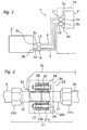
- Fig. 1 shows the configuration of an air conditioner 1 according to this embodiment.
- the air conditioner 1 includes an indoor unit 2 that is installed on the inner side of an outer wall 10 of a building, an outdoor unit 3 that is installed on the outer side of the outer wall 10, a gas side connection line 4 (connection line), a liquid side connection line 5 (connection line), electric insulation devices 11, 12 which are respectively provided between the gas side connection line 4 and a gas side refrigerant line 2a on the indoor unit 2 side and between the liquid side connection line 5 and a liquid side refrigerant line 2b on the indoor unit 2 side, electric insulation devices 13, 14 which are respectively provided between the gas side connection line 4 and a gas side refrigerant line 3a on the outdoor unit 3 side and between the liquid side connection line 5 and a liquid side refrigerant line 3b on the outdoor unit 3 side, electric connection lines 2c, 2d that are respectively connected from the indoor unit 2 to the electric insulation devices 11, 12, and electric connection lines 3c, 3d that are respectively connected from the outdoor unit 3 to the electric
- the gas side connection line 4 and the liquid side connection line 5 are, for example, made from a metal such as copper or the like, and serve to connect the refrigerant lines of the indoor unit 2 and the refrigerant lines of the outdoor unit 3 and allow refrigerant to circulate.
- the refrigerant lines 2a, 2b on the indoor unit 2 side and the refrigerant lines 3a, 3b on the outdoor unit 3 side are, for example, made of a metal such as copper or the like, and are connected to equipment installed inside the indoor unit 2 and the outdoor unit 3.
- the electric insulation device 11 is arranged between the gas side connection line 4 and the gas side refrigerant line 2a of the indoor unit 2, and electrically insulates the gas side connection line 4 and the gas side refrigerant line 2a on the indoor unit 2 side.
- the electric insulation device 12 is arranged between the liquid side connection line 5 and the liquid side refrigerant line 2b of the indoor unit 2, and electrically insulates the liquid side connection line 5 and the liquid side refrigerant line 2b on the indoor unit 2 side.
- the electric insulation device 13 is arranged between the gas side connection line 4 and the gas side refrigerant line 3a of the outdoor unit 3, and electrically insulates the gas side connection line 4 and the gas side refrigerant line 3a on the outdoor unit 3 side.
- the electric insulation device 14 is arranged between the liquid side connection line 5 and the liquid side refrigerant line 3b of the outdoor unit 3, and electrically insulates the liquid side connection line 5 and the liquid side refrigerant line 3b on the outdoor unit 3 side.
- the gas side connection line 4 and the liquid side connection line 5 between the indoor unit 2 and the outdoor unit 3 are electrically insulated from the refrigerant lines 2a, 2b, 3a, 3b on the indoor unit 2 and the outdoor unit 3 sides by means of the electric insulation devices 11-14.
- the electric insulation lines 2c, 2d, 3c, 3d are conductors which serve to transmit electric signals such as control signals and the like between the indoor unit 2 and the outdoor unit 3, and are respectively electrically connected to the gas side connection line 4 and the liquid side connection line 5 via the electric insulation devices 11, 12, 13, 14.
- the gas side connection line 4 functions as an electric line in order to connect the electric connection lines 2c and 3c
- the liquid side connection line 5 functions as an electric line in order to connect the electric connection lines 2d and 3d.
- the electric insulation device 11 includes a refrigerant line connection portion 21 that is connected to the gas side refrigerant line 2a of the indoor unit 2, a connection line connection portion 22 that is connected to the gas side connection line 4, an insulation portion 23 capable of both electrically insulating the refrigerant line connection portion 21 and the gas side connection line 4 and circulating refrigerant, and a terminal portion 24 on which the electric connection line 2c is mounted.
- the refrigerant line connection portion 21 is, for example, made of a metal such as copper or the like, and is connected to the gas side refrigerant line 2a of the indoor unit 2 by means of a flare nut 21 a that is arranged on the refrigerant line 2a side of the indoor unit 2 side.
- the connection line connection portion 22 is connected to the gas side connection line 4 by means of a flare nut 22a that is arranged on the gas side connection line 4 side.
- the refrigerant line connection portion 21 forms an end portion of the gas side connection line 4 side of the gas side refrigerant line 2a
- the connection line connection portion 22 forms an end portion of the gas side refrigerant line 2a side of the gas side connection line 4.
- the insulation portion 23 is formed from an annular first flange 21b that is formed on the end portion of the gas side connection line 4 side of the refrigerant line connection portion 21, an annular second flange 22b that is formed on the end portion of the indoor unit 2 side of the connection line connection portion 22, a gasket 25 that is arranged between the first flange 21 b and the second flange 22b, a plurality of through bolts 26 and nuts 27 that serve to join the first flange 21b and the second flange 22b, a sleeve 28 that lies between the through bolts 26 and the bolt holes of the first flange 21 b and the second flange 22b, and a washer 29 that is interposed between head portions 26a of the through bolts 26 and the first flange 21b.
- the head portions 26a of the through bolts 26 are covered by a coating material composed of an electric insulation material such as ceramic, resin, or the like.
- the first flange 21b, the second flange 22b, and the plurality of through bolts 26 and the nuts 27 are made of a metal.
- the gasket 25 is an annular member that is composed of an electric insulation material such as rubber, resin, or the like.
- the sleeve 28 is a cylindrical member that is composed of an electric insulation material such as a resin.
- the insulation portion 23 is covered by a thermal insulation material.
- the insulation portion 23 described above allows the refrigerant line connection portion 21 and the connection line connection portion 22 to be electrically insulated, and allows refrigerant to circulate.
- the gas side refrigerant line 2a of the indoor unit 2 and the gas side connection line 4 are electrically insulated via the insulation portion 23.
- electric signals can be transmitted via the gas side connection line 4 between the electric connection line 2c of the indoor unit 2 and the electric connection line 3c of the outdoor unit 3.
- electric signals can be transmitted via the liquid side connection line 5 between the electric connection line 2d of the indoor unit 2 and the electric connection line 3d of the outdoor unit 3.
- the special characteristics of the electric insulation device of the present embodiment are as follows:
- each of the electric insulation devices 11-14 of the air conditioner of this embodiment the connections between the refrigerant lines and the refrigerant line connection portions of the indoor unit 2 and the indoor unit 3 are performed on the exterior of the indoor unit 2 and the outdoor unit 3.
- each of the electric insulation devices 11-14 is an integral unit that is formed from the refrigerant line connection portion 21, the connection line connection portion 22, and the insulation portion 23, and are disposed on the exterior of the indoor unit 2 and the outdoor unit 3.
- the work efficiency of the installation of the indoor unit 2 and the outdoor unit 3 will improve because the electric insulation devices can be easily replaced, and the locations where the indoor unit 2 and the outdoor unit 3 can be installed are not limited.
- the indoor unit 2 and the outdoor unit 3 can be easily wired with the electric insulation devices 11-14, because each of the electric insulation devices 11-14 further include the terminal portion 24 on which the electric connection lines 2c, 2d, 3c, 3d.
- both the work efficiency during installation can be improved, and the reliability with respect to refrigerant leakage, short-circuits, and the like can be improved, because the joining of the first flange 21b and the second flange 22b of the insulation portion 24 can be performed at the factory or the like, and it will not be necessary to perform this task at the installation site.
- the electric insulation devices 11-14 of the air conditioner of this embodiment can be applied to previously installed air conditioners because, as noted above, they are units that are separate from the indoor unit 2 and the outdoor unit 3.
- the present embodiment has the same basic structure as that of the first embodiment, and only the structure of the insulation portion of the electric insulation device is different.
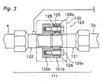
- An insulation portion 123 of the present embodiment will be described below with reference to Fig. 3. Note that here, an electric insulation device 111 that corresponds to the electric insulation device 11 of the first embodiment will be described, and a description of other electric insulation devices 112, 113,. 114 will be omitted.
- the insulation portion 123 of the electric insulation device 111 includes is formed from an annular first flange 121b that is formed on the end portion of the gas side connection line 4 side of a refrigerant line connection portion 121, an annular second flange 122b that is formed on the end portion of the indoor unit 2 side of the connection line connection portion 122, a gasket 125 that is arranged between the first flange 121 b and the second flange 122b, a plurality of push bolts 126 that serve to join the first flange 121b and the second flange 122b, and a sleeve 128 that lies between the bolt holes of the first flange 121b and the push bolts 126.
- the sleeve 128 includes a washer portion 128a that is interposed between head portions 126a of the push bolts 126 and the first flange 121b.
- the head portions 126a of the push bolts 126 are covered by a coating material composed of an electric insulation material such as ceramic, resin, or the like.
- the first flange 121 b, the second flange 122b, and the plurality of push bolts 126 are made of a metal.
- the gasket 125 is an annular member that is composed of an electric insulation material such as rubber, resin, or the like.
- the sleeve 128 is a cylindrical member that is composed of an electric insulation material such as resin. Then, the insulation portion 123 is covered by a thermal insulation material 130.
- connection between the refrigerant line connection portions and the connection line connection portions and each refrigerant line and connection line is a flare nut connection, but may instead be connected by means of brazing.
- the work efficiency of the installation of the indoor unit and the outdoor unit can be improved, because the electric insulation unit is a separate unit from the indoor unit and the outdoor unit.
Landscapes
- Engineering & Computer Science (AREA)
- General Engineering & Computer Science (AREA)
- Mechanical Engineering (AREA)
- Chemical & Material Sciences (AREA)
- Combustion & Propulsion (AREA)
- Other Air-Conditioning Systems (AREA)
- Flanged Joints, Insulating Joints, And Other Joints (AREA)
Abstract
Description
Claims (3)
- An electric insulation device (11, 12, 13, 14) of an air conditioner divided into an indoor unit (2) and an outdoor unit (3), the electric insulation device (11, 12, 13, 14) serving to electrically insulate connection lines (4, 5) that connect refrigerant lines (2a, 2b) of the indoor unit (2) with refrigerant lines (2a, 3b) of the outdoor unit (3) and circulate refrigerant, from the refrigerant lines (2a, 2b) of the indoor unit (2) or the refrigerant lines (3a, 3b) of the outdoor unit (3), the electric insulation device (11, 12, 13, 14) comprising:a refrigerant line connection portion (21) that is installed on an exterior of the indoor unit (2) and the outdoor unit (3), and connected respectively to the refrigerant line (2a, 2b) of the indoor unit (2) and the refrigerant line (3a, 3b) of the outdoor unit (3);a connection line connection portion (22) that is connected to the connection line (4, 5); andan insulation portion (23) that can both electrically insulate the refrigerant line connection portion (21) and the connection line connection portion (22), and circulate refrigerant.
- The electric insulation device (11, 12, 13, 14) of an air conditioner disclosed in claim 1, wherein a terminal portion (24) on which an electric connection line (2c, 2d, 3c, 3d) is mounted in order to transmit electric signals from the indoor unit (2) and the outdoor unit (3) to the connection lines (4, 5) is arranged between the connection line connection portion (22) and the insulation portion (23).
- An air conditioner, comprising:an indoor unit (2);an outdoor unit (3);connection lines (4, 5) that connect refrigerant lines (2a, 2b) of the indoor unit (2) and refrigerant lines (3a, 3b) of the outdoor unit (3), and circulate refrigerant; andelectric insulation devices (11, 12, 13, 14) disclosed in claims 1 or 2 that are respectively arranged between the refrigerant lines (2a, 2b) and the connection lines (4, 5) of the indoor unit (2), and between the refrigerant lines (3a, 3b) and the connection lines (4, 5) of the outdoor unit (3).
Applications Claiming Priority (3)
| Application Number | Priority Date | Filing Date | Title |
|---|---|---|---|
| JP2002074381A JP3985556B2 (en) | 2002-03-18 | 2002-03-18 | Electrical insulation device for air conditioner and air conditioner having the same |
| JP2002074381 | 2002-03-18 | ||
| PCT/JP2003/002816 WO2003078902A1 (en) | 2002-03-18 | 2003-03-10 | Electric insulating device of air conditioner, and air conditioner with the device |
Publications (2)
| Publication Number | Publication Date |
|---|---|
| EP1486738A1 true EP1486738A1 (en) | 2004-12-15 |
| EP1486738A4 EP1486738A4 (en) | 2008-05-14 |
Family
ID=28035302
Family Applications (1)
| Application Number | Title | Priority Date | Filing Date |
|---|---|---|---|
| EP03708532A Withdrawn EP1486738A4 (en) | 2002-03-18 | 2003-03-10 | DEVICE FOR ELECTRICALLY INSULATING AN AIR CONDITIONER AND AIR CONDITIONER COMPRISING SAID DEVICE |
Country Status (6)
| Country | Link |
|---|---|
| US (1) | US7013665B2 (en) |
| EP (1) | EP1486738A4 (en) |
| JP (1) | JP3985556B2 (en) |
| CN (1) | CN1322274C (en) |
| AU (1) | AU2003213446A1 (en) |
| WO (1) | WO2003078902A1 (en) |
Cited By (1)
| Publication number | Priority date | Publication date | Assignee | Title |
|---|---|---|---|---|
| US20100293974A1 (en) * | 2004-03-09 | 2010-11-25 | Mitsubishi Electric Corporation | Airconditioning equipment, signal transmission method, and signal transmission method for air conditioning equipment |
Families Citing this family (10)
| Publication number | Priority date | Publication date | Assignee | Title |
|---|---|---|---|---|
| JP4033218B2 (en) | 2005-11-01 | 2008-01-16 | ダイキン工業株式会社 | Shut-off valve mounting structure, and outdoor unit of air conditioner including the same |
| CN101702353B (en) * | 2009-11-13 | 2011-07-20 | 江苏科技大学 | Flexible joint connected by heterogeneous metals and connecting method thereof |
| US20110219795A1 (en) * | 2010-03-10 | 2011-09-15 | Chisun Ahn | Core assembly for air conditioner and air conditioner having the same |
| CN103375497A (en) * | 2012-04-12 | 2013-10-30 | 东风扬子江汽车(武汉)有限责任公司 | Electric-motor insulation coupling |
| CN103574904B (en) * | 2013-10-29 | 2016-05-18 | 广州班尼斯电器有限公司 | A kind of electric water separator for air energy heat pump water heater |
| JP6398372B2 (en) * | 2014-06-27 | 2018-10-03 | ダイキン工業株式会社 | Air conditioner floor-mounted indoor unit |
| JP6135705B2 (en) * | 2015-04-06 | 2017-05-31 | ダイキン工業株式会社 | User side air conditioner |
| MX2017014487A (en) * | 2015-05-12 | 2018-06-07 | Alliance Sustainable Energy | Split heating and cooling systems. |
| EP4187167A1 (en) | 2017-12-26 | 2023-05-31 | Trane International Inc. | Hvac product for flammable refrigerant |
| CN119687537A (en) * | 2023-09-22 | 2025-03-25 | 青岛海尔智慧楼宇科技有限公司 | Air conditioning communication transmission system |
Family Cites Families (12)
| Publication number | Priority date | Publication date | Assignee | Title |
|---|---|---|---|---|
| JPS581379B2 (en) * | 1974-10-08 | 1983-01-11 | ミズオチ シヨウケン | Ryuutai Kenchi Cable |
| JPS51128024U (en) | 1975-04-14 | 1976-10-16 | ||
| JPS6037372B2 (en) * | 1979-08-21 | 1985-08-26 | 松下電器産業株式会社 | piping equipment |
| FR2586078B1 (en) * | 1985-08-07 | 1988-05-06 | Telecommunications Sa | CONNECTING DEVICE FOR A FLUID SUPPLY SYSTEM |
| DE3641062A1 (en) * | 1986-12-01 | 1988-06-16 | Kyburz & Cie | Insulating pipe connection |
| FI82858C (en) * | 1989-06-30 | 1991-04-25 | Rauma Repola Oy | ANSLUTNINGSDON FOER TRYCKMEDIUMSLANG. |
| JPH0765783B2 (en) | 1990-04-13 | 1995-07-19 | 三菱電機株式会社 | Operation controller for separate air conditioner |
| JPH0765783A (en) | 1993-08-31 | 1995-03-10 | Kawasaki Steel Corp | Secondary ion mass spectrometer |
| JPH1054498A (en) | 1996-08-09 | 1998-02-24 | Nippon Jiyaketsuto Kk | Pipe joint insulation unit and method of construction |
| TW339401B (en) * | 1997-02-28 | 1998-09-01 | Sanyo Electric Co | Coolant branching device for an air conditioner |
| JP2000329273A (en) * | 1999-05-18 | 2000-11-30 | Kubota Corp | Insulation structure of pipe joint |
| CN2420561Y (en) * | 2000-04-26 | 2001-02-21 | 大金工业株式会社 | Match pipe connection structure for air conditioner |
-
2002
- 2002-03-18 JP JP2002074381A patent/JP3985556B2/en not_active Expired - Fee Related
-
2003
- 2003-03-10 US US10/506,635 patent/US7013665B2/en not_active Expired - Fee Related
- 2003-03-10 CN CNB038043521A patent/CN1322274C/en not_active Expired - Fee Related
- 2003-03-10 EP EP03708532A patent/EP1486738A4/en not_active Withdrawn
- 2003-03-10 AU AU2003213446A patent/AU2003213446A1/en not_active Abandoned
- 2003-03-10 WO PCT/JP2003/002816 patent/WO2003078902A1/en not_active Ceased
Cited By (3)
| Publication number | Priority date | Publication date | Assignee | Title |
|---|---|---|---|---|
| US20100293974A1 (en) * | 2004-03-09 | 2010-11-25 | Mitsubishi Electric Corporation | Airconditioning equipment, signal transmission method, and signal transmission method for air conditioning equipment |
| US8733119B2 (en) | 2004-03-09 | 2014-05-27 | Mitsubishi Electric Corporation | Air conditioning equipment, signal transmission method, and signal transmission method for air conditioning equipment |
| US8807444B2 (en) * | 2004-03-09 | 2014-08-19 | Mitsubishi Electric Corporation | Air conditioning equipment, signal transmission method, and signal transmission method for air conditioning equipment |
Also Published As
| Publication number | Publication date |
|---|---|
| WO2003078902A1 (en) | 2003-09-25 |
| JP3985556B2 (en) | 2007-10-03 |
| EP1486738A4 (en) | 2008-05-14 |
| CN1322274C (en) | 2007-06-20 |
| US7013665B2 (en) | 2006-03-21 |
| CN1636122A (en) | 2005-07-06 |
| AU2003213446A1 (en) | 2003-09-29 |
| JP2003269750A (en) | 2003-09-25 |
| US20050166624A1 (en) | 2005-08-04 |
Similar Documents
| Publication | Publication Date | Title |
|---|---|---|
| US7017362B2 (en) | Connection structure of coolant pipe of air conditioner | |
| US7013665B2 (en) | Electric insulating device of air conditioner, and air conditioner with the device | |
| EP2461445B1 (en) | Methods and systems for coupling busbar components | |
| CA2702906C (en) | Integrated insulator seal and shield assemblies | |
| JP4030335B2 (en) | Lightning arrester for coaxial cable | |
| CN206875612U (en) | Outdoor unit of air conditioner and air conditioner | |
| JP2011163490A (en) | Refrigerant pipe, and air conditioner using the refrigerant pipe | |
| EP2763243B1 (en) | Connecting element and method of manufacturing a connecting element | |
| JP2003164048A (en) | Jumper wire support gripper | |
| JP2001280563A (en) | Insulation fitting for gas piping | |
| US6555751B1 (en) | Straight joint for cable | |
| JPH05196260A (en) | Air conditioner | |
| JP2024142422A (en) | Piping and wiring inspection method | |
| JPH0526892Y2 (en) | ||
| JP2723117B2 (en) | Air conditioner with antenna connection terminal | |
| CN121749606A (en) | A YBF motor junction box connector | |
| CN201207562Y (en) | Outdoor type water-proof device for electronic device plug | |
| JPH0914571A (en) | Corrosion protection structure of pipe fittings | |
| JP2021092269A (en) | Piping connection structure | |
| CN103381840A (en) | Auxiliary device of train, and mounting method thereof | |
| JP2014007888A (en) | High-voltage wiring penetrating part, installation method of the same, and high-voltage wiring penetration structure | |
| JPH11178188A (en) | Cable connection terminal | |
| JP2002058164A (en) | Power supply | |
| JPH1074654A (en) | Mold type current transformer | |
| JPH1018647A (en) | Electromagnetic shield structure for very large space |
Legal Events
| Date | Code | Title | Description |
|---|---|---|---|
| PUAI | Public reference made under article 153(3) epc to a published international application that has entered the european phase |
Free format text: ORIGINAL CODE: 0009012 |
|
| 17P | Request for examination filed |
Effective date: 20040830 |
|
| AK | Designated contracting states |
Kind code of ref document: A1 Designated state(s): AT BE BG CH CY CZ DE DK EE ES FI FR GB GR HU IE IT LI LU MC NL PT RO SE SI SK TR |
|
| AX | Request for extension of the european patent |
Extension state: AL LT LV MK |
|
| A4 | Supplementary search report drawn up and despatched |
Effective date: 20080416 |
|
| 17Q | First examination report despatched |
Effective date: 20080805 |
|
| GRAP | Despatch of communication of intention to grant a patent |
Free format text: ORIGINAL CODE: EPIDOSNIGR1 |
|
| RTI1 | Title (correction) |
Free format text: AIR CONDITIONER ASSEMBLY WITH ELECTRIC INSULATING DEVICE |
|
| STAA | Information on the status of an ep patent application or granted ep patent |
Free format text: STATUS: THE APPLICATION IS DEEMED TO BE WITHDRAWN |
|
| 18D | Application deemed to be withdrawn |
Effective date: 20111109 |