EP1486692A1 - Constant velocity universal joint - Google Patents
Constant velocity universal joint Download PDFInfo
- Publication number
- EP1486692A1 EP1486692A1 EP04076563A EP04076563A EP1486692A1 EP 1486692 A1 EP1486692 A1 EP 1486692A1 EP 04076563 A EP04076563 A EP 04076563A EP 04076563 A EP04076563 A EP 04076563A EP 1486692 A1 EP1486692 A1 EP 1486692A1
- Authority
- EP
- European Patent Office
- Prior art keywords
- ball
- joint center
- groove pairs
- grooves
- groove
- Prior art date
- Legal status (The legal status is an assumption and is not a legal conclusion. Google has not performed a legal analysis and makes no representation as to the accuracy of the status listed.)
- Granted
Links
- 238000010276 construction Methods 0.000 description 1
Images




Classifications
-
- F—MECHANICAL ENGINEERING; LIGHTING; HEATING; WEAPONS; BLASTING
- F16—ENGINEERING ELEMENTS AND UNITS; GENERAL MEASURES FOR PRODUCING AND MAINTAINING EFFECTIVE FUNCTIONING OF MACHINES OR INSTALLATIONS; THERMAL INSULATION IN GENERAL
- F16D—COUPLINGS FOR TRANSMITTING ROTATION; CLUTCHES; BRAKES
- F16D3/00—Yielding couplings, i.e. with means permitting movement between the connected parts during the drive
- F16D3/16—Universal joints in which flexibility is produced by means of pivots or sliding or rolling connecting parts
- F16D3/20—Universal joints in which flexibility is produced by means of pivots or sliding or rolling connecting parts one coupling part entering a sleeve of the other coupling part and connected thereto by sliding or rolling members
- F16D3/22—Universal joints in which flexibility is produced by means of pivots or sliding or rolling connecting parts one coupling part entering a sleeve of the other coupling part and connected thereto by sliding or rolling members the rolling members being balls, rollers, or the like, guided in grooves or sockets in both coupling parts
- F16D3/223—Universal joints in which flexibility is produced by means of pivots or sliding or rolling connecting parts one coupling part entering a sleeve of the other coupling part and connected thereto by sliding or rolling members the rolling members being balls, rollers, or the like, guided in grooves or sockets in both coupling parts the rolling members being guided in grooves in both coupling parts
-
- F—MECHANICAL ENGINEERING; LIGHTING; HEATING; WEAPONS; BLASTING
- F16—ENGINEERING ELEMENTS AND UNITS; GENERAL MEASURES FOR PRODUCING AND MAINTAINING EFFECTIVE FUNCTIONING OF MACHINES OR INSTALLATIONS; THERMAL INSULATION IN GENERAL
- F16D—COUPLINGS FOR TRANSMITTING ROTATION; CLUTCHES; BRAKES
- F16D3/00—Yielding couplings, i.e. with means permitting movement between the connected parts during the drive
- F16D3/16—Universal joints in which flexibility is produced by means of pivots or sliding or rolling connecting parts
- F16D3/20—Universal joints in which flexibility is produced by means of pivots or sliding or rolling connecting parts one coupling part entering a sleeve of the other coupling part and connected thereto by sliding or rolling members
- F16D3/22—Universal joints in which flexibility is produced by means of pivots or sliding or rolling connecting parts one coupling part entering a sleeve of the other coupling part and connected thereto by sliding or rolling members the rolling members being balls, rollers, or the like, guided in grooves or sockets in both coupling parts
- F16D3/223—Universal joints in which flexibility is produced by means of pivots or sliding or rolling connecting parts one coupling part entering a sleeve of the other coupling part and connected thereto by sliding or rolling members the rolling members being balls, rollers, or the like, guided in grooves or sockets in both coupling parts the rolling members being guided in grooves in both coupling parts
- F16D3/224—Universal joints in which flexibility is produced by means of pivots or sliding or rolling connecting parts one coupling part entering a sleeve of the other coupling part and connected thereto by sliding or rolling members the rolling members being balls, rollers, or the like, guided in grooves or sockets in both coupling parts the rolling members being guided in grooves in both coupling parts the groove centre-lines in each coupling part lying on a sphere
-
- F—MECHANICAL ENGINEERING; LIGHTING; HEATING; WEAPONS; BLASTING
- F16—ENGINEERING ELEMENTS AND UNITS; GENERAL MEASURES FOR PRODUCING AND MAINTAINING EFFECTIVE FUNCTIONING OF MACHINES OR INSTALLATIONS; THERMAL INSULATION IN GENERAL
- F16D—COUPLINGS FOR TRANSMITTING ROTATION; CLUTCHES; BRAKES
- F16D3/00—Yielding couplings, i.e. with means permitting movement between the connected parts during the drive
- F16D3/16—Universal joints in which flexibility is produced by means of pivots or sliding or rolling connecting parts
- F16D3/20—Universal joints in which flexibility is produced by means of pivots or sliding or rolling connecting parts one coupling part entering a sleeve of the other coupling part and connected thereto by sliding or rolling members
- F16D3/22—Universal joints in which flexibility is produced by means of pivots or sliding or rolling connecting parts one coupling part entering a sleeve of the other coupling part and connected thereto by sliding or rolling members the rolling members being balls, rollers, or the like, guided in grooves or sockets in both coupling parts
- F16D3/223—Universal joints in which flexibility is produced by means of pivots or sliding or rolling connecting parts one coupling part entering a sleeve of the other coupling part and connected thereto by sliding or rolling members the rolling members being balls, rollers, or the like, guided in grooves or sockets in both coupling parts the rolling members being guided in grooves in both coupling parts
- F16D2003/22309—Details of grooves
-
- Y—GENERAL TAGGING OF NEW TECHNOLOGICAL DEVELOPMENTS; GENERAL TAGGING OF CROSS-SECTIONAL TECHNOLOGIES SPANNING OVER SEVERAL SECTIONS OF THE IPC; TECHNICAL SUBJECTS COVERED BY FORMER USPC CROSS-REFERENCE ART COLLECTIONS [XRACs] AND DIGESTS
- Y10—TECHNICAL SUBJECTS COVERED BY FORMER USPC
- Y10S—TECHNICAL SUBJECTS COVERED BY FORMER USPC CROSS-REFERENCE ART COLLECTIONS [XRACs] AND DIGESTS
- Y10S464/00—Rotary shafts, gudgeons, housings, and flexible couplings for rotary shafts
- Y10S464/904—Homokinetic coupling
- Y10S464/906—Torque transmitted via radially spaced balls
Definitions
- This invention relates generally to universal joints and more particularly to a constant velocity universal joint.
- a constant velocity universal joint has inner and outer spherical races coupled together by a series of balls engaging generally parallel grooves in the races. It is important that the speed of rotation of the two races remains always the same, whatever the angular adjustment of the axes of the two races. This depends on maintaining the plane of the balls so as to bisect the angle of adjustment. At present, this is accomplished by placing a spherical cage between the races, slotted to hold the balls. However, the provision of a cage increases cost, adds an additional part, and generates excess heat in operation.
- the constant velocity universal joint of the present invention dispenses with the cage.
- the two races spherically engage one another.
- Each ball is confined by a pair of grooves consisting of a groove in the outer race and a groove in the inner race, with the grooves of each pair in crossing relation to one another so that the ball is properly located.
- a ball can drop out when torque is applied to one of the races and one groove tends to rotate relative to the other.
- all outer race grooves are circumferentially inclined in one direction
- all inner race grooves are circumferentially inclined in the opposite direction
- alternate outer race groove centers are offset to one side of the spherical center
- the remaining outer race groove centers are offset to the opposite side of the spherical center
- the inner race groove center of each groove pair is offset from the spherical center to the side opposite the side to which the center of the paired outer race groove is offset.
- alternate outer race grooves are circumferentially inclined in one direction and the remaining outer race grooves are circumferentially inclined in the opposite direction.
- Each inner race groove is inclined oppositely to the outer race groove with which it is paired. All outer race groove centers are offset to the same side of the spherical center and all inner race groove centers are offset to the same (but opposite) side of the spherical center.
- the inner race groove center of each groove pair is offset from the spherical center to a side opposite the side to which the center of the paired outer race groove is offset.
- An object of the invention is to provide a constant velocity universal joint having the foregoing features and capabilities.
- a constant velocity universal joint 20 having an outer race 22 which is integral with or otherwise secured to a shaft 24, and an inner race 26 which is integral with or otherwise attached to a shaft 28.
- the outer race 22 has an inner, spherical, concave surface 30 disposed about a longitudinal axis 32 of the outer race.
- the inner race 26 has an outer, spherical, convex surface 34 disposed about a longitudinal axis 36 of the inner race.
- the inner and outer races 22, 26 and their spherical surfaces 30 and 34 have a common center 38, which is the center of the joint, and the surfaces 30 and 34 are spherically engaged with one another.
- the concave surface 30 of the outer race 20 has a plurality (in this embodiment 8) of arcuate, generally longitudinally extending, circumferentially spaced outer race grooves 40 and 42 which are alternated with one another.
- the convex surface 34 of the inner race 26 has the same number of arcuate, generally longitudinally extending, circumferentially spaced inner race grooves 44 and 46 with are alternated with one another.
- the grooves 40 and 44 of the two races are paired with one another to provide a plurality of groove pairs 48 ( Figure 12).
- the grooves 42 and 46 of the two races are paired with one another to provide a plurality of groove pairs 50 ( Figure 14).
- All of the outer race grooves 40 and 42 are inclined circumferentially in one direction and all of the inner race grooves 44 and 46 are inclined circumferentially in the opposite direction so that the grooves 40, 44 of each of the groove pairs 48 are in crossing relation to one another, and the grooves 42, 46 of each of the groove pairs 50 are in crossing relation to one another. See FIGURES 4, 5, 10 and 11.
- a torque-transmitting ball 52 is confined by the outer race groove and the inner race groove of each of the groove pairs 48 and 50.
- the alternate outer race grooves 40 are arcuate and have centers of curvature located at 53 offset to one side of the joint center 38 ( Figure 7).
- the remaining outer race grooves 42 are arcuate and have centers of curvature located at 54 offset to the opposite side of the joint center 38 ( Figure 9).
- the alternate inner race grooves 44 have centers of curvature at 54 and the remaining inner race grooves 46 have centers of curvature at 53. See FIGURES 6 and 8.
- the centers 53 and 54 are offset the same distance from the joint center 38.
- a constant velocity universal joint 120 having an outer race 122 which is splined or otherwise secured to a shaft 124, and an inner race 126 which is integral with or otherwise attached to a shaft 128.
- the outer race 122 has an inner, spherical, concave surface 130 disposed about a longitudinal axis 132 of the outer race.
- the inner race 126 has an outer, spherical, convex surface 134 disposed about a longitudinal axis 136 of the inner race.
- the inner and outer races 122, 126 and their spherical surfaces 130 and 134 have a common center 138, which is the center of the joint, and the surfaces 130 and 134 are spherically engaged with one another.
- the concave surface 130 of the outer race 120 has a plurality (again there are eight) of arcuate, generally longitudinally extending, circumferentially spaced outer race grooves 140 and 142 which are alternated with one another.
- the convex surface 134 of the inner race 126 has the same number of arcuate, generally longitudinally extending, circumferentially spaced inner race grooves 144 and 146 which are alternated with one another.
- the grooves 140 and 144 of the two races are paired with one another to provide a plurality of groove pairs 148 ( Figure 24).
- the grooves 142 and 146 of the two races are paired with one another to provide a plurality of groove pairs 150 ( Figure 26).
- Alternate grooves 140 of the outer race 120 are inclined circumferentially in one direction and the remaining grooves 142 are inclined circumferentially in the opposite direction.
- Alternate grooves 144 of the inner race 126 are circumferentially inclined oppositely to the grooves 140 with which they are paired, and the remaining inner race grooves 146 are circumferentially inclined oppositely to the grooves 142 with which they are paired. Thus the grooves of each pair are inclined oppositely to one another.
- a torque-transmitting ball 152 is confined by the outer race groove and the inner race groove of each of the groove pairs 148 and 150.
- All of the outer race grooves 140 and 142 are arcuate and have centers of curvature located at 153 offset to one side of the joint center 138.
- All of the inner race grooves 144 and 146 are arcuate and have centers of curvature located at 154 offset to the opposite side of the joint center 138.
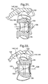
- the centers 153 and 154 are offset the same distance from the joint center 138. See Figures 21 and 22.
- Figures 12-15 there will be seen diagrammatically in Figures 12-15, the relationship of two crossing grooves 40 and 44 of a groove pair 48, and two crossing grooves 42 and 46 of a groove pair 50. All of the grooves are of uneven depth throughout their length due to the offset of the groove centers from the spherical center.
- Figure 12 In the perspective view of the groove pair 48 ( Figure 12), it will be seen that there is greater groove depth to the right than to the left.
- the inner race groove 44 tends to rotate into the paper (as noted by the arrow 160 in the perspective view)
- the front wall of the inner race groove 44 will push the ball against the back wall of the outer race groove 40.
- the forces from both groove walls will drive the ball to the right as shown in the front view. Since the grooves 40 and 44 have more depth to the right, nothing will stop movement of the balls to the right, except for the existence of the groove pairs 50.
- the grooves 42 and 46 are of less depth to the right.
- the front wall of the inner race groove 46 will push the ball against the back wall of the outer race groove 42.
- These forces shown in the front view will drive the ball to the right.
- the ball cannot get through the narrower channel of the grooves 42 and 46.
- the ball becomes locked in the crossing pair of the grooves 42, 46 and stops the rotation of the inner race groove relative to the outer race groove.
- all of the groove pairs 50 will stop the relative rotation of all of the groove pairs 48 so that all balls will be contained in the crossing groove pairs.
- the outer race will thus rotate together with the inner race. It should be noted that in this case only the groove pairs 48 will carry the torque.
- FIGURES 16-27 there is seen diagrammatically in Figures 24-27, the relationship of two crossing grooves 140 and 144 of a groove pair 148 and two crossing grooves 142 and 146 of a groove pair 150. All inner race groove centers are offset symmetrically to one side of the sphere center and all outer race groove centers are offset symmetrically to the opposite side of the groove center, and the grooves in each race are alternately inclined in opposite directions.
- the inner race groove 144 of the groove pair 148 is inclined out of the paper, while the inner race groove 146 of the pair 150 are inclined into the paper. All of the outer race grooves 140 and 142 are symmetrically inclined in the opposite direction to their paired inner race grooves 146 and 148.
- All groove pairs have less groove depth to the left and more depth to the right. Assuming that the inner race grooves tend to rotate into paper as indicated by the arrow 160, then the front walls of the inner race grooves will tend to push the ball against the back walls of the outer race grooves. The forces tend to drive the ball of the groove pair 148 to the right, which is the direction of more groove depth. But the forces of groove pair 150 tend to drive the ball to the left, in which direction the crossed groove pair has less depth. Accordingly, the ball gets stuck and stops the relative rotation of the inner and outer races, so that the outer race rotates with the inner race.
- the crossing groove pairs maintain the balls in a plane which bisects the angle of adjustment of the two races, and the speed of rotation of the two races remains always the same whatever the angular adjustment.
Landscapes
- Engineering & Computer Science (AREA)
- General Engineering & Computer Science (AREA)
- Mechanical Engineering (AREA)
- Rolling Contact Bearings (AREA)
- Pivots And Pivotal Connections (AREA)
- Paper (AREA)
- Nonmetallic Welding Materials (AREA)
- Diaphragms For Electromechanical Transducers (AREA)
Abstract
Description
- This invention relates generally to universal joints and more particularly to a constant velocity universal joint.
- Typically, a constant velocity universal joint has inner and outer spherical races coupled together by a series of balls engaging generally parallel grooves in the races. It is important that the speed of rotation of the two races remains always the same, whatever the angular adjustment of the axes of the two races. This depends on maintaining the plane of the balls so as to bisect the angle of adjustment. At present, this is accomplished by placing a spherical cage between the races, slotted to hold the balls. However, the provision of a cage increases cost, adds an additional part, and generates excess heat in operation.
- The constant velocity universal joint of the present invention dispenses with the cage. The two races spherically engage one another. Each ball is confined by a pair of grooves consisting of a groove in the outer race and a groove in the inner race, with the grooves of each pair in crossing relation to one another so that the ball is properly located. However, a ball can drop out when torque is applied to one of the races and one groove tends to rotate relative to the other. To overcome this problem, and in accordance with one embodiment of this invention, all outer race grooves are circumferentially inclined in one direction, all inner race grooves are circumferentially inclined in the opposite direction, alternate outer race groove centers are offset to one side of the spherical center, the remaining outer race groove centers are offset to the opposite side of the spherical center, and the inner race groove center of each groove pair is offset from the spherical center to the side opposite the side to which the center of the paired outer race groove is offset.
- In accordance with a second embodiment of the invention, alternate outer race grooves are circumferentially inclined in one direction and the remaining outer race grooves are circumferentially inclined in the opposite direction. Each inner race groove is inclined oppositely to the outer race groove with which it is paired. All outer race groove centers are offset to the same side of the spherical center and all inner race groove centers are offset to the same (but opposite) side of the spherical center. The inner race groove center of each groove pair is offset from the spherical center to a side opposite the side to which the center of the paired outer race groove is offset.
- An object of the invention is to provide a constant velocity universal joint having the foregoing features and capabilities.
- Other objects, features and advantages of the invention will become more apparent as the following description proceeds, especially when considered with the accompanying drawings.
- Figure 1 is an end view of a universal joint constructed in accordance with this invention;
- Figure 2 is a sectional view taken on the
line 2--2 in Figure 1; - Figure 3 is a sectional view taken on the line 3--3 in Figure 2;
- Figure 4 is a sectional view of the outer race in Figure 2;
- Figure 5 is a side elevational view of the inner race;
- Figure 6 is a fragmentary sectional view taken on the
line 6--6 in Figure 1; - Figure 7 is a fragmentary sectional view taken on the
line 7--7 in Figure 1; - Figure 8 is a fragmentary sectional view taken on the
line 8--8 in Figure 1; - Figure 9 is a fragmentary sectional view taken on the line 9--9 in Figure 1;
- Figure 10 is a development of the outer and inner races, showing the groove pattern thereof;
- Figure 11 is a development of the outer and inner races, showing the groove patterns overlain with one another;
- Figure 12 is a diagrammatic perspective view showing a ball between one pair of outer and inner race grooves;
- Figure 13 is a diagrammatic view looking down on the showing in Figure 12;
- Figure 14 is a diagrammatic perspective view showing a ball between another pair of outer and inner race grooves;
- Figure 15 is a diagrammatic view looking down on the showing in Figure 14;
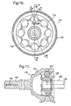
- Figure 16 is an end view of a universal joint of modified construction;
- Figure 17 is a sectional view taken on the
line 17--17 in Figure 16; - Figure 18 is a sectional view of the outer race shown in Figure 16, and
taken on the
line 18--18 in Figure 16; - Figure 19 is a side elevational view of the inner race of the embodiment shown in Figure 16;
- Figure 20 is a development of the outer and inner races of the embodiment of Figure 16, showing the groove pattern thereof;
- Figure 21 is a fragmentary sectional view taken on the
line 21--21 in Figure 16; - Figure 22 is a fragmentary sectional view taken on the
line 22--22 in Figure 16; - Figure 23 is a development of the outer and inner races, showing the groove patterns in Figure 20 overlain with one another;
- Figure 24 is a diagrammatic perspective view showing a ball between one pair of outer and inner race grooves of the universal joint shown in Figure 16;
- Figure 25 is a diagrammatic view looking down on the showing in Figure 24;
- Figure 26 is a diagrammatic perspective view showing a ball between another pair of outer and inner race grooves of the universal joint shown in Figure 16; and
- Figure 27 is a diagrammatic view looking down on the showing in Figure 26.
-
- Referring now more particularly to the drawings and especially Figures 1-15, there is shown a constant velocity
universal joint 20 having anouter race 22 which is integral with or otherwise secured to ashaft 24, and aninner race 26 which is integral with or otherwise attached to ashaft 28. Theouter race 22 has an inner, spherical,concave surface 30 disposed about alongitudinal axis 32 of the outer race. Theinner race 26 has an outer, spherical,convex surface 34 disposed about alongitudinal axis 36 of the inner race. The inner andouter races spherical surfaces common center 38, which is the center of the joint, and thesurfaces - The
concave surface 30 of theouter race 20 has a plurality (in this embodiment 8) of arcuate, generally longitudinally extending, circumferentially spacedouter race grooves convex surface 34 of theinner race 26 has the same number of arcuate, generally longitudinally extending, circumferentially spacedinner race grooves grooves grooves - All of the
outer race grooves inner race grooves grooves groove pairs 48 are in crossing relation to one another, and thegrooves groove pairs 50 are in crossing relation to one another. See FIGURES 4, 5, 10 and 11. - A torque-transmitting
ball 52 is confined by the outer race groove and the inner race groove of each of thegroove pairs - The alternate
outer race grooves 40 are arcuate and have centers of curvature located at 53 offset to one side of the joint center 38 (Figure 7). The remainingouter race grooves 42 are arcuate and have centers of curvature located at 54 offset to the opposite side of the joint center 38 (Figure 9). The alternateinner race grooves 44 have centers of curvature at 54 and the remaininginner race grooves 46 have centers of curvature at 53. See FIGURES 6 and 8. Thecenters joint center 38. - Referring now to Figures 16-27, there is shown a constant velocity
universal joint 120 having anouter race 122 which is splined or otherwise secured to ashaft 124, and aninner race 126 which is integral with or otherwise attached to ashaft 128. Theouter race 122 has an inner, spherical,concave surface 130 disposed about alongitudinal axis 132 of the outer race. Theinner race 126 has an outer, spherical,convex surface 134 disposed about alongitudinal axis 136 of the inner race. The inner andouter races spherical surfaces common center 138, which is the center of the joint, and thesurfaces - The
concave surface 130 of theouter race 120 has a plurality (again there are eight) of arcuate, generally longitudinally extending, circumferentially spacedouter race grooves convex surface 134 of theinner race 126 has the same number of arcuate, generally longitudinally extending, circumferentially spacedinner race grooves grooves grooves -
Alternate grooves 140 of theouter race 120 are inclined circumferentially in one direction and the remaininggrooves 142 are inclined circumferentially in the opposite direction.Alternate grooves 144 of theinner race 126 are circumferentially inclined oppositely to thegrooves 140 with which they are paired, and the remaininginner race grooves 146 are circumferentially inclined oppositely to thegrooves 142 with which they are paired. Thus the grooves of each pair are inclined oppositely to one another. - A torque-transmitting
ball 152 is confined by the outer race groove and the inner race groove of each of the groove pairs 148 and 150. - All of the
outer race grooves joint center 138. All of theinner race grooves joint center 138. Thecenters joint center 138. See Figures 21 and 22. - As pointed out above, even with crossing grooves, the balls can drop out when torque is applied to one of the races. However this situation is avoided by both of the embodiments of the invention previously described.
- Referring first to the embodiment in Figures 1-15, there will be seen diagrammatically in Figures 12-15, the relationship of two crossing
grooves groove pair 48, and two crossinggrooves groove pair 50. All of the grooves are of uneven depth throughout their length due to the offset of the groove centers from the spherical center. In the perspective view of the groove pair 48 (Figure 12), it will be seen that there is greater groove depth to the right than to the left. As theinner race groove 44 tends to rotate into the paper (as noted by thearrow 160 in the perspective view), the front wall of theinner race groove 44 will push the ball against the back wall of theouter race groove 40. The forces from both groove walls will drive the ball to the right as shown in the front view. Since thegrooves - Referring to the perspective view of the groove pair 50 (Figure 14), it will be seen that the
grooves inner race groove 46 tends to rotate into the paper, the front wall of theinner race groove 46 will push the ball against the back wall of theouter race groove 42. These forces shown in the front view will drive the ball to the right. But the ball cannot get through the narrower channel of thegrooves grooves - Considering now the second embodiment in FIGURES 16-27, there is seen diagrammatically in Figures 24-27, the relationship of two crossing
grooves groove pair 148 and two crossinggrooves groove pair 150. All inner race groove centers are offset symmetrically to one side of the sphere center and all outer race groove centers are offset symmetrically to the opposite side of the groove center, and the grooves in each race are alternately inclined in opposite directions. - As seen in the front view of Figures 24 and 26, the
inner race groove 144 of thegroove pair 148 is inclined out of the paper, while theinner race groove 146 of thepair 150 are inclined into the paper. All of theouter race grooves inner race grooves - All groove pairs have less groove depth to the left and more depth to the right. Assuming that the inner race grooves tend to rotate into paper as indicated by the
arrow 160, then the front walls of the inner race grooves will tend to push the ball against the back walls of the outer race grooves. The forces tend to drive the ball of thegroove pair 148 to the right, which is the direction of more groove depth. But the forces ofgroove pair 150 tend to drive the ball to the left, in which direction the crossed groove pair has less depth. Accordingly, the ball gets stuck and stops the relative rotation of the inner and outer races, so that the outer race rotates with the inner race. - In both embodiments of the invention, the crossing groove pairs maintain the balls in a plane which bisects the angle of adjustment of the two races, and the speed of rotation of the two races remains always the same whatever the angular adjustment.
Claims (9)
- A constant velocity universal joint comprising:an outer race (22,122) having an inner, spherical, concave surface (30,130) disposed about a longitudinal axis of said outer race,a plurality of arcuate, generally longitudinally extending, circumferentially spaced outer race grooves (40,140; 42,142) in said concave surface of said outer race,an inner race (26,126) having an outer, spherical, convex surface (34,134) disposed about a longitudinal axis of said inner race,a plurality of arcuate, generally longitudinally extending, circumferentially spaced inner race grooves (44,144; 46,146) in said convex surface of said inner race,said inner race (26,126) being disposed concentrically within said outer race (22,122) with said convex surface spherically engaged with said concave surface for relative angular movement of said inner and outer races about a common joint center (38,138),each of said inner race grooves (44,144; 46,146) being arranged opposite a corresponding one of the outer race grooves (40,140; 42,142) to define a plurality of ball-groove pairs (48,50; 148,150),the grooves of each ball-groove pair being disposed in transverse crossing relation to one another, anda plurality of torque-transmitting balls (52,152), one of said balls being disposed in each of said ball-groove pairs for movement therealong during such relative angular movement of said inner and outer races.
- The constant velocity universal joint of claim 1, wherein the outer race grooves (40,140; 42, 142) of one or more of the ball-groove pairs have centers (53,153) which are axially spaced from said joint center (38,138) to one side of said joint center, the inner race grooves (44,144; 46,146) of said one or more of the ball-groove pairs have centers (54,154) which are axially spaced from said joint center (38,138) to said one side of said joint center (38,138), the outer race grooves of the ball-groove pairs other than said one or more of the ball-groove pairs have centers which are axially spaced from said joint center (38,138) to a side of the joint center which is opposite said one side of said joint center, and the inner race grooves of the ball-groove pairs other than said one or more groove pairs have centers which are axially spaced from said joint center (38,138) to the side of the joint center which is opposite said one side of the joint center.
- The constant velocity universal joint of claim 1, wherein the outer race grooves (40; 42) of all of the ball-groove pairs are inclined in one circumferential direction, and the inner race grooves (44; 46) of all of the ball-groove pairs are inclined in a direction which is opposite said one circumferential direction.
- The constant velocity universal joint of claim 3, wherein the outer race grooves (40) of one or more of the ball-groove pairs have centers which are axially spaced from said joint center to one side of said joint center (38), the inner race grooves (44) of said one or more of the ball-groove pairs have centers which are axially spaced from said joint center (38) to said one side of said joint center, the outer race grooves of the ball-groove pairs other than said one or more of the ball-groove pairs have centers which are axially spaced from said joint center (38) to a side of the joint center which is opposite said one side of said joint center, and the inner race grooves of the ball-groove pairs other than said one or more groove pairs have centers which are axially spaced from said joint center (38) to the side of the joint center which is opposite said one side of the joint center.
- The constant velocity universal joint of claim 4, wherein said one or more ball-groove pairs constitute one-half the total number of said ball-groove pairs.
- The constant velocity universal joint of claim 1, wherein the outer race grooves (40,140; 42,142) of all of the ball-groove pairs have centers (53,153) which are axially spaced from said joint center to one side of said joint center, and the inner race grooves (44,144; 46,146) of all of the ball-groove pairs have centers (54,154) which are axially spaced from said joint center to a side of said joint center (38,138) which is opposite said one side of said joint center.
- The constant velocity universal joint of claim 1, wherein the outer race grooves (140) of one or more ball-groove pairs are inclined in one circumferential direction, the inner race grooves (144) of said one or more ball-groove pairs are inclined in an opposite circumferential direction, the outer race grooves (142) of the ball-groove pairs other than said one or more ball-groove pairs are inclined in said opposite circumferential direction, and the inner race grooves (146) of the ball-groove pairs other than said one or more ball-groove pairs are inclined in said one circumferential direction.
- The constant velocity universal joint of claim 7, wherein the outer race grooves (140,142) of all of the ball-groove pairs have centers (153) which are axially spaced from said joint center (138) to one side of said joint center, and the inner race grooves (144,146) of all of the ball-groove pairs have centers (154) which are axially spaced from said joint center (138) to a side of said joint center which is opposite said one side of said joint center.
- The constant velocity universal joint of claim 8, wherein said one or more ball-groove pairs constitute one-half the total number of said ball-groove pairs.
Applications Claiming Priority (2)
| Application Number | Priority Date | Filing Date | Title |
|---|---|---|---|
| US457622 | 1989-12-27 | ||
| US10/457,622 US7008326B2 (en) | 2003-06-09 | 2003-06-09 | Constant velocity universal joint |
Publications (2)
| Publication Number | Publication Date |
|---|---|
| EP1486692A1 true EP1486692A1 (en) | 2004-12-15 |
| EP1486692B1 EP1486692B1 (en) | 2007-07-18 |
Family
ID=33299625
Family Applications (1)
| Application Number | Title | Priority Date | Filing Date |
|---|---|---|---|
| EP04076563A Expired - Lifetime EP1486692B1 (en) | 2003-06-09 | 2004-05-27 | Constant velocity universal joint |
Country Status (4)
| Country | Link |
|---|---|
| US (1) | US7008326B2 (en) |
| EP (1) | EP1486692B1 (en) |
| AT (1) | ATE367536T1 (en) |
| DE (1) | DE602004007584T2 (en) |
Families Citing this family (5)
| Publication number | Priority date | Publication date | Assignee | Title |
|---|---|---|---|---|
| US8382600B2 (en) * | 2009-09-18 | 2013-02-26 | Hyundai Wia Corporation | Cross groove type constant velocity joint with composite groove patterns |
| US8500566B2 (en) * | 2009-09-18 | 2013-08-06 | Hyundai Wia Corporation | Cross groove type constant velocity joint |
| US8444495B2 (en) * | 2009-10-20 | 2013-05-21 | Hyundai Wia Corporation | Cross groove type constant velocity joint |
| JP6113459B2 (en) * | 2012-11-08 | 2017-04-12 | Ntn株式会社 | Fixed constant velocity universal joint |
| WO2017020061A1 (en) * | 2015-08-05 | 2017-02-09 | Edward Wechner | Large articulation constant velocity joint |
Citations (6)
| Publication number | Priority date | Publication date | Assignee | Title |
|---|---|---|---|---|
| GB200297A (en) * | 1922-05-20 | 1923-07-12 | Arthur Samuel Hammond | Improvements in universal joints |
| US2325460A (en) * | 1940-09-20 | 1943-07-27 | Walter E Amberg | Constant velocity universal joint |
| GB987572A (en) * | 1960-06-25 | 1965-03-31 | Rheinmetall Gmbh | Improvements in or relating to universal joints |
| GB995137A (en) * | 1961-02-02 | 1965-06-16 | Henry Faure | Constant-speed universal joint |
| US3592023A (en) * | 1968-06-27 | 1971-07-13 | Nippon Seiko Kk | Constant velocity universal joint |
| DE19507859A1 (en) * | 1995-03-08 | 1996-09-12 | Loehr & Bromkamp Gmbh | Synchronised rotating linkage assembly |
Family Cites Families (31)
| Publication number | Priority date | Publication date | Assignee | Title |
|---|---|---|---|---|
| US1886847A (en) | 1927-04-02 | 1932-11-08 | Gen Motors Corp | Universal joint |
| US2134563A (en) | 1936-10-10 | 1938-10-25 | Ernest R Koppel | Universal joint |
| US2361135A (en) | 1941-10-30 | 1944-10-24 | Bendix Aviat Corp | Universal joint |
| US2321448A (en) | 1941-12-19 | 1943-06-08 | Borg Warner | Constant velocity universal joint |
| US2559563A (en) | 1945-07-02 | 1951-07-03 | Universal Products Co Inc | Constant velocity joint |
| US2578764A (en) | 1946-03-11 | 1951-12-18 | Trbojevich Nikola | Constant velocity universal joint |
| US2578763A (en) * | 1946-03-11 | 1951-12-18 | Trbojevich Nikola | Constant velocity universal joint |
| US3002364A (en) * | 1956-05-03 | 1961-10-03 | Bellomo Andrea | Universal joint |
| US2928263A (en) | 1957-07-23 | 1960-03-15 | Devos Gaston Louis Arthur | Homokinetic universal joint |
| US2875600A (en) * | 1957-12-19 | 1959-03-03 | Jr Fred F Miller | Constant velocity universal joint |
| US3071943A (en) | 1960-02-20 | 1963-01-08 | Girling Ltd | Universal joints |
| US3083548A (en) * | 1960-06-25 | 1963-04-02 | Rheinmetall Gmbh | Universal joint |
| DE1229343B (en) | 1963-08-16 | 1966-11-24 | Daimler Benz Ag | Constant velocity sliding joint coupling, especially for the final drive of motor vehicles |
| US3747469A (en) * | 1969-05-22 | 1973-07-24 | Gen Electric | Linear linkless ammunition feed system |
| JPS4841172B1 (en) * | 1970-01-21 | 1973-12-05 | ||
| FR2078478A5 (en) | 1971-02-11 | 1971-11-05 | Dba | |
| US4083202A (en) | 1976-08-05 | 1978-04-11 | General Motors Corporation | Stroking universal joint housing |
| US4449956A (en) | 1980-06-17 | 1984-05-22 | Yasuo Ueno | Constant-velocity universal joint |
| US4377385A (en) | 1981-01-08 | 1983-03-22 | Sindelar William F | Homokinetic universal joint |
| US6186899B1 (en) | 1998-11-25 | 2001-02-13 | Delphi Technologies, Inc. | Constant velocity joint |
| US6159103A (en) | 1998-12-17 | 2000-12-12 | Delphi Technologies, Inc. | Constant velocity universal joint |
| US6206785B1 (en) | 1999-03-05 | 2001-03-27 | Delphi Technologies, Inc. | Constant velocity universal joint and method |
| US6190260B1 (en) | 1999-05-06 | 2001-02-20 | Delphi Technologies, Incx. | Tripod universal joint and method of its manufacture |
| EP1264114B1 (en) | 2000-02-16 | 2009-04-22 | Delphi Technologies, Inc. | Constant velocity joint having fixed centre and crossed grooves |
| JP3469878B2 (en) | 2000-02-16 | 2003-11-25 | デルファイ・テクノロジーズ・インコーポレーテッド | Constant speed stroke joint |
| JP4827291B2 (en) | 2000-10-16 | 2011-11-30 | ジーエム・グローバル・テクノロジー・オペレーションズ・インコーポレーテッド | Tripod type constant velocity joint |
| US6390925B1 (en) | 2000-10-16 | 2002-05-21 | Delphi Technologies, Inc. | Retainer assembly |
| US6443844B1 (en) | 2000-12-05 | 2002-09-03 | Delphi Technologies, Inc. | Constant velocity stroking joint |
| US6533667B2 (en) | 2000-12-21 | 2003-03-18 | Delphi Technologies, Inc. | Tripot constant velocity joint having ball modules |
| US6582313B2 (en) | 2000-12-22 | 2003-06-24 | Delphi Technologies, Inc. | Constant velocity stroking joint having recirculating spline balls |
| US6616537B2 (en) | 2001-09-20 | 2003-09-09 | Delphi Technologies, Inc. | Constant velocity joint |
-
2003
- 2003-06-09 US US10/457,622 patent/US7008326B2/en not_active Expired - Fee Related
-
2004
- 2004-05-27 AT AT04076563T patent/ATE367536T1/en not_active IP Right Cessation
- 2004-05-27 DE DE602004007584T patent/DE602004007584T2/en not_active Expired - Lifetime
- 2004-05-27 EP EP04076563A patent/EP1486692B1/en not_active Expired - Lifetime
Patent Citations (6)
| Publication number | Priority date | Publication date | Assignee | Title |
|---|---|---|---|---|
| GB200297A (en) * | 1922-05-20 | 1923-07-12 | Arthur Samuel Hammond | Improvements in universal joints |
| US2325460A (en) * | 1940-09-20 | 1943-07-27 | Walter E Amberg | Constant velocity universal joint |
| GB987572A (en) * | 1960-06-25 | 1965-03-31 | Rheinmetall Gmbh | Improvements in or relating to universal joints |
| GB995137A (en) * | 1961-02-02 | 1965-06-16 | Henry Faure | Constant-speed universal joint |
| US3592023A (en) * | 1968-06-27 | 1971-07-13 | Nippon Seiko Kk | Constant velocity universal joint |
| DE19507859A1 (en) * | 1995-03-08 | 1996-09-12 | Loehr & Bromkamp Gmbh | Synchronised rotating linkage assembly |
Non-Patent Citations (1)
| Title |
|---|
| PATENT ABSTRACTS OF JAPAN vol. 1998, no. 04 31 March 1998 (1998-03-31) * |
Also Published As
| Publication number | Publication date |
|---|---|
| DE602004007584D1 (en) | 2007-08-30 |
| US7008326B2 (en) | 2006-03-07 |
| DE602004007584T2 (en) | 2008-04-17 |
| EP1486692B1 (en) | 2007-07-18 |
| ATE367536T1 (en) | 2007-08-15 |
| US20040248658A1 (en) | 2004-12-09 |
Similar Documents
| Publication | Publication Date | Title |
|---|---|---|
| US6468164B2 (en) | Constant velocity joint having fixed center and crossed grooves | |
| US2046584A (en) | Universal joint | |
| US1975758A (en) | Universal joint | |
| JP5101430B2 (en) | Fixed constant velocity universal joint | |
| JP5227397B2 (en) | Constant velocity indentation ball joint with low indentation force | |
| US5026325A (en) | Constant velocity ratio plunging universal joint | |
| US4325232A (en) | Constant velocity universal joint | |
| CN105531490B (en) | The constant-velocity joint of retrograde orbit joint form | |
| US8382600B2 (en) | Cross groove type constant velocity joint with composite groove patterns | |
| US2902844A (en) | Universal joint | |
| JP2007503555A (en) | Counter track joint for large bending angles | |
| US20050124422A1 (en) | Cross-straight groove joint | |
| WO2014054366A1 (en) | Fixed constant-velocity universal joint | |
| US7008326B2 (en) | Constant velocity universal joint | |
| US8535167B2 (en) | Constant velocity joint of tripod type | |
| JPH0633945A (en) | Constant-velocity universal joint with crossed groove | |
| JP6199159B2 (en) | Fixed constant velocity universal joint | |
| JP5882050B2 (en) | Fixed constant velocity universal joint | |
| JP5615873B2 (en) | Fixed constant velocity universal joint | |
| EP1529978A1 (en) | Constant velocity joint having friction reducing web locators | |
| JP6832629B2 (en) | Fixed constant velocity universal joint | |
| JP6796931B2 (en) | Fixed constant velocity universal joint | |
| US3067595A (en) | Homokinetic universal joint | |
| WO2020203221A1 (en) | Fixed constant-velocity universal joint | |
| US4377385A (en) | Homokinetic universal joint |
Legal Events
| Date | Code | Title | Description |
|---|---|---|---|
| PUAI | Public reference made under article 153(3) epc to a published international application that has entered the european phase |
Free format text: ORIGINAL CODE: 0009012 |
|
| AK | Designated contracting states |
Kind code of ref document: A1 Designated state(s): AT BE BG CH CY CZ DE DK EE ES FI FR GB GR HU IE IT LI LU MC NL PL PT RO SE SI SK TR |
|
| AX | Request for extension of the european patent |
Extension state: AL HR LT LV MK |
|
| 17P | Request for examination filed |
Effective date: 20050615 |
|
| AKX | Designation fees paid |
Designated state(s): AT BE BG CH CY CZ DE DK EE ES FI FR GB GR HU IE IT LI LU MC NL PL PT RO SE SI SK TR |
|
| GRAP | Despatch of communication of intention to grant a patent |
Free format text: ORIGINAL CODE: EPIDOSNIGR1 |
|
| GRAS | Grant fee paid |
Free format text: ORIGINAL CODE: EPIDOSNIGR3 |
|
| GRAA | (expected) grant |
Free format text: ORIGINAL CODE: 0009210 |
|
| AK | Designated contracting states |
Kind code of ref document: B1 Designated state(s): AT BE BG CH CY CZ DE DK EE ES FI FR GB GR HU IE IT LI LU MC NL PL PT RO SE SI SK TR |
|
| REG | Reference to a national code |
Ref country code: GB Ref legal event code: FG4D |
|
| REG | Reference to a national code |
Ref country code: CH Ref legal event code: EP |
|
| REF | Corresponds to: |
Ref document number: 602004007584 Country of ref document: DE Date of ref document: 20070830 Kind code of ref document: P |
|
| REG | Reference to a national code |
Ref country code: IE Ref legal event code: FG4D |
|
| ET | Fr: translation filed | ||
| PG25 | Lapsed in a contracting state [announced via postgrant information from national office to epo] |
Ref country code: BG Free format text: LAPSE BECAUSE OF FAILURE TO SUBMIT A TRANSLATION OF THE DESCRIPTION OR TO PAY THE FEE WITHIN THE PRESCRIBED TIME-LIMIT Effective date: 20071018 Ref country code: PT Free format text: LAPSE BECAUSE OF FAILURE TO SUBMIT A TRANSLATION OF THE DESCRIPTION OR TO PAY THE FEE WITHIN THE PRESCRIBED TIME-LIMIT Effective date: 20071218 Ref country code: NL Free format text: LAPSE BECAUSE OF FAILURE TO SUBMIT A TRANSLATION OF THE DESCRIPTION OR TO PAY THE FEE WITHIN THE PRESCRIBED TIME-LIMIT Effective date: 20070718 Ref country code: ES Free format text: LAPSE BECAUSE OF FAILURE TO SUBMIT A TRANSLATION OF THE DESCRIPTION OR TO PAY THE FEE WITHIN THE PRESCRIBED TIME-LIMIT Effective date: 20071029 Ref country code: FI Free format text: LAPSE BECAUSE OF FAILURE TO SUBMIT A TRANSLATION OF THE DESCRIPTION OR TO PAY THE FEE WITHIN THE PRESCRIBED TIME-LIMIT Effective date: 20070718 |
|
| REG | Reference to a national code |
Ref country code: CH Ref legal event code: PL |
|
| NLV1 | Nl: lapsed or annulled due to failure to fulfill the requirements of art. 29p and 29m of the patents act | ||
| PG25 | Lapsed in a contracting state [announced via postgrant information from national office to epo] |
Ref country code: LI Free format text: LAPSE BECAUSE OF FAILURE TO SUBMIT A TRANSLATION OF THE DESCRIPTION OR TO PAY THE FEE WITHIN THE PRESCRIBED TIME-LIMIT Effective date: 20070718 Ref country code: AT Free format text: LAPSE BECAUSE OF FAILURE TO SUBMIT A TRANSLATION OF THE DESCRIPTION OR TO PAY THE FEE WITHIN THE PRESCRIBED TIME-LIMIT Effective date: 20070718 Ref country code: PL Free format text: LAPSE BECAUSE OF FAILURE TO SUBMIT A TRANSLATION OF THE DESCRIPTION OR TO PAY THE FEE WITHIN THE PRESCRIBED TIME-LIMIT Effective date: 20070718 Ref country code: CH Free format text: LAPSE BECAUSE OF FAILURE TO SUBMIT A TRANSLATION OF THE DESCRIPTION OR TO PAY THE FEE WITHIN THE PRESCRIBED TIME-LIMIT Effective date: 20070718 |
|
| PG25 | Lapsed in a contracting state [announced via postgrant information from national office to epo] |
Ref country code: BE Free format text: LAPSE BECAUSE OF FAILURE TO SUBMIT A TRANSLATION OF THE DESCRIPTION OR TO PAY THE FEE WITHIN THE PRESCRIBED TIME-LIMIT Effective date: 20070718 |
|
| PG25 | Lapsed in a contracting state [announced via postgrant information from national office to epo] |
Ref country code: GR Free format text: LAPSE BECAUSE OF FAILURE TO SUBMIT A TRANSLATION OF THE DESCRIPTION OR TO PAY THE FEE WITHIN THE PRESCRIBED TIME-LIMIT Effective date: 20071019 Ref country code: DK Free format text: LAPSE BECAUSE OF FAILURE TO SUBMIT A TRANSLATION OF THE DESCRIPTION OR TO PAY THE FEE WITHIN THE PRESCRIBED TIME-LIMIT Effective date: 20070718 |
|
| PLBE | No opposition filed within time limit |
Free format text: ORIGINAL CODE: 0009261 |
|
| STAA | Information on the status of an ep patent application or granted ep patent |
Free format text: STATUS: NO OPPOSITION FILED WITHIN TIME LIMIT |
|
| PG25 | Lapsed in a contracting state [announced via postgrant information from national office to epo] |
Ref country code: SK Free format text: LAPSE BECAUSE OF FAILURE TO SUBMIT A TRANSLATION OF THE DESCRIPTION OR TO PAY THE FEE WITHIN THE PRESCRIBED TIME-LIMIT Effective date: 20070718 Ref country code: CZ Free format text: LAPSE BECAUSE OF FAILURE TO SUBMIT A TRANSLATION OF THE DESCRIPTION OR TO PAY THE FEE WITHIN THE PRESCRIBED TIME-LIMIT Effective date: 20070718 |
|
| 26N | No opposition filed |
Effective date: 20080421 |
|
| PG25 | Lapsed in a contracting state [announced via postgrant information from national office to epo] |
Ref country code: RO Free format text: LAPSE BECAUSE OF FAILURE TO SUBMIT A TRANSLATION OF THE DESCRIPTION OR TO PAY THE FEE WITHIN THE PRESCRIBED TIME-LIMIT Effective date: 20070718 Ref country code: SE Free format text: LAPSE BECAUSE OF FAILURE TO SUBMIT A TRANSLATION OF THE DESCRIPTION OR TO PAY THE FEE WITHIN THE PRESCRIBED TIME-LIMIT Effective date: 20071018 |
|
| PG25 | Lapsed in a contracting state [announced via postgrant information from national office to epo] |
Ref country code: MC Free format text: LAPSE BECAUSE OF NON-PAYMENT OF DUE FEES Effective date: 20080531 |
|
| GBPC | Gb: european patent ceased through non-payment of renewal fee |
Effective date: 20080527 |
|
| PG25 | Lapsed in a contracting state [announced via postgrant information from national office to epo] |
Ref country code: EE Free format text: LAPSE BECAUSE OF FAILURE TO SUBMIT A TRANSLATION OF THE DESCRIPTION OR TO PAY THE FEE WITHIN THE PRESCRIBED TIME-LIMIT Effective date: 20070718 Ref country code: IE Free format text: LAPSE BECAUSE OF NON-PAYMENT OF DUE FEES Effective date: 20080527 |
|
| PG25 | Lapsed in a contracting state [announced via postgrant information from national office to epo] |
Ref country code: SI Free format text: LAPSE BECAUSE OF FAILURE TO SUBMIT A TRANSLATION OF THE DESCRIPTION OR TO PAY THE FEE WITHIN THE PRESCRIBED TIME-LIMIT Effective date: 20070718 Ref country code: GB Free format text: LAPSE BECAUSE OF NON-PAYMENT OF DUE FEES Effective date: 20080527 |
|
| PG25 | Lapsed in a contracting state [announced via postgrant information from national office to epo] |
Ref country code: CY Free format text: LAPSE BECAUSE OF FAILURE TO SUBMIT A TRANSLATION OF THE DESCRIPTION OR TO PAY THE FEE WITHIN THE PRESCRIBED TIME-LIMIT Effective date: 20070718 |
|
| PG25 | Lapsed in a contracting state [announced via postgrant information from national office to epo] |
Ref country code: HU Free format text: LAPSE BECAUSE OF FAILURE TO SUBMIT A TRANSLATION OF THE DESCRIPTION OR TO PAY THE FEE WITHIN THE PRESCRIBED TIME-LIMIT Effective date: 20080119 Ref country code: LU Free format text: LAPSE BECAUSE OF NON-PAYMENT OF DUE FEES Effective date: 20080527 |
|
| REG | Reference to a national code |
Ref country code: FR Ref legal event code: TP |
|
| PG25 | Lapsed in a contracting state [announced via postgrant information from national office to epo] |
Ref country code: TR Free format text: LAPSE BECAUSE OF FAILURE TO SUBMIT A TRANSLATION OF THE DESCRIPTION OR TO PAY THE FEE WITHIN THE PRESCRIBED TIME-LIMIT Effective date: 20070718 |
|
| PG25 | Lapsed in a contracting state [announced via postgrant information from national office to epo] |
Ref country code: IT Free format text: LAPSE BECAUSE OF NON-PAYMENT OF DUE FEES Effective date: 20080531 |
|
| REG | Reference to a national code |
Ref country code: DE Ref legal event code: R081 Ref document number: 602004007584 Country of ref document: DE Owner name: STEERING SOLUTIONS IP HOLDING CORP., US Free format text: FORMER OWNER: DELPHI TECHNOLOGIES, INC., TROY, US Effective date: 20110412 Ref country code: DE Ref legal event code: R081 Ref document number: 602004007584 Country of ref document: DE Owner name: GM GLOBAL TECHNOLOGY OPERATIONS LLC (N. D. GES, US Free format text: FORMER OWNER: DELPHI TECHNOLOGIES, INC., TROY, US Effective date: 20110412 Ref country code: DE Ref legal event code: R081 Ref document number: 602004007584 Country of ref document: DE Owner name: GM GLOBAL TECHNOLOGY OPERATIONS LLC (N. D. GES, US Free format text: FORMER OWNER: DELPHI TECHNOLOGIES, INC., TROY, MICH., US Effective date: 20110412 Ref country code: DE Ref legal event code: R081 Ref document number: 602004007584 Country of ref document: DE Owner name: STEERING SOLUTIONS IP HOLDING CORP., SAGINAW, US Free format text: FORMER OWNER: DELPHI TECHNOLOGIES, INC., TROY, MICH., US Effective date: 20110412 |
|
| PGFP | Annual fee paid to national office [announced via postgrant information from national office to epo] |
Ref country code: FR Payment date: 20120607 Year of fee payment: 9 |
|
| REG | Reference to a national code |
Ref country code: DE Ref legal event code: R082 Ref document number: 602004007584 Country of ref document: DE Representative=s name: MANITZ, FINSTERWALD & PARTNER GBR, DE |
|
| REG | Reference to a national code |
Ref country code: DE Ref legal event code: R082 Ref document number: 602004007584 Country of ref document: DE Representative=s name: MANITZ FINSTERWALD PATENTANWAELTE PARTMBB, DE Effective date: 20121019 Ref country code: DE Ref legal event code: R082 Ref document number: 602004007584 Country of ref document: DE Representative=s name: MANITZ, FINSTERWALD & PARTNER GBR, DE Effective date: 20121019 Ref country code: DE Ref legal event code: R081 Ref document number: 602004007584 Country of ref document: DE Owner name: GM GLOBAL TECHNOLOGY OPERATIONS LLC (N. D. GES, US Free format text: FORMER OWNER: GM GLOBAL TECHNOLOGY OPERATIONS, INC., DETROIT, US Effective date: 20121019 Ref country code: DE Ref legal event code: R081 Ref document number: 602004007584 Country of ref document: DE Owner name: STEERING SOLUTIONS IP HOLDING CORP., US Free format text: FORMER OWNER: GM GLOBAL TECHNOLOGY OPERATIONS, INC., DETROIT, US Effective date: 20121019 Ref country code: DE Ref legal event code: R081 Ref document number: 602004007584 Country of ref document: DE Owner name: GM GLOBAL TECHNOLOGY OPERATIONS LLC (N. D. GES, US Free format text: FORMER OWNER: GM GLOBAL TECHNOLOGY OPERATIONS, INC., DETROIT, MICH., US Effective date: 20121019 Ref country code: DE Ref legal event code: R081 Ref document number: 602004007584 Country of ref document: DE Owner name: STEERING SOLUTIONS IP HOLDING CORP., SAGINAW, US Free format text: FORMER OWNER: GM GLOBAL TECHNOLOGY OPERATIONS, INC., DETROIT, MICH., US Effective date: 20121019 |
|
| REG | Reference to a national code |
Ref country code: DE Ref legal event code: R082 Ref document number: 602004007584 Country of ref document: DE Representative=s name: MANITZ, FINSTERWALD & PARTNER GBR, DE |
|
| REG | Reference to a national code |
Ref country code: DE Ref legal event code: R081 Ref document number: 602004007584 Country of ref document: DE Owner name: STEERING SOLUTIONS IP HOLDING CORP., US Free format text: FORMER OWNER: GM GLOBAL TECHNOLOGY OPERATIONS LLC (N. D. GES. D. STAATES DELAWARE), DETROIT, US Effective date: 20130313 Ref country code: DE Ref legal event code: R082 Ref document number: 602004007584 Country of ref document: DE Representative=s name: MANITZ FINSTERWALD PATENTANWAELTE PARTMBB, DE Effective date: 20130313 Ref country code: DE Ref legal event code: R081 Ref document number: 602004007584 Country of ref document: DE Owner name: GM GLOBAL TECHNOLOGY OPERATIONS LLC (N. D. GES, US Free format text: FORMER OWNER: GM GLOBAL TECHNOLOGY OPERATIONS LLC (N. D. GES. D. STAATES DELAWARE), DETROIT, US Effective date: 20130313 Ref country code: DE Ref legal event code: R082 Ref document number: 602004007584 Country of ref document: DE Representative=s name: MANITZ, FINSTERWALD & PARTNER GBR, DE Effective date: 20130313 Ref country code: DE Ref legal event code: R081 Ref document number: 602004007584 Country of ref document: DE Owner name: STEERING SOLUTIONS IP HOLDING CORP., SAGINAW, US Free format text: FORMER OWNER: GM GLOBAL TECHNOLOGY OPERATIONS LLC (N. D. GES. D. STAATES DELAWARE), DETROIT, MICH., US Effective date: 20130313 Ref country code: DE Ref legal event code: R081 Ref document number: 602004007584 Country of ref document: DE Owner name: GM GLOBAL TECHNOLOGY OPERATIONS LLC (N. D. GES, US Free format text: FORMER OWNER: GM GLOBAL TECHNOLOGY OPERATIONS LLC (N. D. GES. D. STAATES DELAWARE), DETROIT, MICH., US Effective date: 20130313 |
|
| REG | Reference to a national code |
Ref country code: FR Ref legal event code: ST Effective date: 20140131 |
|
| PG25 | Lapsed in a contracting state [announced via postgrant information from national office to epo] |
Ref country code: FR Free format text: LAPSE BECAUSE OF NON-PAYMENT OF DUE FEES Effective date: 20130531 |
|
| REG | Reference to a national code |
Ref country code: FR Ref legal event code: CD Owner name: GM GLOBAL TECHNOLOGY OPERATIONS LLC, US Effective date: 20150723 Ref country code: FR Ref legal event code: CD Owner name: STEERING SOLUTIONS IP HOLDING CORPORATION, US Effective date: 20150723 Ref country code: FR Ref legal event code: TQ Owner name: STEERING SOLUTIONS IP HOLDING CORPORATION, US Effective date: 20150723 Ref country code: FR Ref legal event code: TQ Owner name: GM GLOBAL TECHNOLOGY OPERATIONS LLC, US Effective date: 20150723 |
|
| PGFP | Annual fee paid to national office [announced via postgrant information from national office to epo] |
Ref country code: DE Payment date: 20170530 Year of fee payment: 14 |
|
| REG | Reference to a national code |
Ref country code: DE Ref legal event code: R119 Ref document number: 602004007584 Country of ref document: DE |
|
| PG25 | Lapsed in a contracting state [announced via postgrant information from national office to epo] |
Ref country code: DE Free format text: LAPSE BECAUSE OF NON-PAYMENT OF DUE FEES Effective date: 20181201 |