EP1486651A1 - Unit for supplying combustion air to the cylinders of an endothermic engine - Google Patents
Unit for supplying combustion air to the cylinders of an endothermic engine Download PDFInfo
- Publication number
- EP1486651A1 EP1486651A1 EP04102646A EP04102646A EP1486651A1 EP 1486651 A1 EP1486651 A1 EP 1486651A1 EP 04102646 A EP04102646 A EP 04102646A EP 04102646 A EP04102646 A EP 04102646A EP 1486651 A1 EP1486651 A1 EP 1486651A1
- Authority
- EP
- European Patent Office
- Prior art keywords
- opening
- bulkhead
- gasket
- unit according
- unit
- Prior art date
- Legal status (The legal status is an assumption and is not a legal conclusion. Google has not performed a legal analysis and makes no representation as to the accuracy of the status listed.)
- Granted
Links
- 238000002485 combustion reaction Methods 0.000 title claims abstract description 15
- 230000008878 coupling Effects 0.000 claims description 6
- 238000010168 coupling process Methods 0.000 claims description 6
- 238000005859 coupling reaction Methods 0.000 claims description 6
- 230000000284 resting effect Effects 0.000 claims description 4
- 238000002347 injection Methods 0.000 claims description 2
- 239000007924 injection Substances 0.000 claims description 2
- 239000000853 adhesive Substances 0.000 description 1
- 230000001070 adhesive effect Effects 0.000 description 1
- 238000006073 displacement reaction Methods 0.000 description 1
- 238000001746 injection moulding Methods 0.000 description 1
Images
Classifications
-
- F—MECHANICAL ENGINEERING; LIGHTING; HEATING; WEAPONS; BLASTING
- F02—COMBUSTION ENGINES; HOT-GAS OR COMBUSTION-PRODUCT ENGINE PLANTS
- F02B—INTERNAL-COMBUSTION PISTON ENGINES; COMBUSTION ENGINES IN GENERAL
- F02B27/00—Use of kinetic or wave energy of charge in induction systems, or of combustion residues in exhaust systems, for improving quantity of charge or for increasing removal of combustion residues
- F02B27/02—Use of kinetic or wave energy of charge in induction systems, or of combustion residues in exhaust systems, for improving quantity of charge or for increasing removal of combustion residues the systems having variable, i.e. adjustable, cross-sectional areas, chambers of variable volume, or like variable means
- F02B27/0226—Use of kinetic or wave energy of charge in induction systems, or of combustion residues in exhaust systems, for improving quantity of charge or for increasing removal of combustion residues the systems having variable, i.e. adjustable, cross-sectional areas, chambers of variable volume, or like variable means characterised by the means generating the charging effect
- F02B27/0247—Plenum chambers; Resonance chambers or resonance pipes
- F02B27/0263—Plenum chambers; Resonance chambers or resonance pipes the plenum chamber and at least one of the intake ducts having a common wall, and the intake ducts wrap partially around the plenum chamber, i.e. snail-type
-
- F—MECHANICAL ENGINEERING; LIGHTING; HEATING; WEAPONS; BLASTING
- F02—COMBUSTION ENGINES; HOT-GAS OR COMBUSTION-PRODUCT ENGINE PLANTS
- F02B—INTERNAL-COMBUSTION PISTON ENGINES; COMBUSTION ENGINES IN GENERAL
- F02B27/00—Use of kinetic or wave energy of charge in induction systems, or of combustion residues in exhaust systems, for improving quantity of charge or for increasing removal of combustion residues
- F02B27/02—Use of kinetic or wave energy of charge in induction systems, or of combustion residues in exhaust systems, for improving quantity of charge or for increasing removal of combustion residues the systems having variable, i.e. adjustable, cross-sectional areas, chambers of variable volume, or like variable means
-
- F—MECHANICAL ENGINEERING; LIGHTING; HEATING; WEAPONS; BLASTING
- F02—COMBUSTION ENGINES; HOT-GAS OR COMBUSTION-PRODUCT ENGINE PLANTS
- F02B—INTERNAL-COMBUSTION PISTON ENGINES; COMBUSTION ENGINES IN GENERAL
- F02B27/00—Use of kinetic or wave energy of charge in induction systems, or of combustion residues in exhaust systems, for improving quantity of charge or for increasing removal of combustion residues
- F02B27/02—Use of kinetic or wave energy of charge in induction systems, or of combustion residues in exhaust systems, for improving quantity of charge or for increasing removal of combustion residues the systems having variable, i.e. adjustable, cross-sectional areas, chambers of variable volume, or like variable means
- F02B27/0205—Use of kinetic or wave energy of charge in induction systems, or of combustion residues in exhaust systems, for improving quantity of charge or for increasing removal of combustion residues the systems having variable, i.e. adjustable, cross-sectional areas, chambers of variable volume, or like variable means characterised by the charging effect
- F02B27/0215—Oscillating pipe charging, i.e. variable intake pipe length charging
-
- F—MECHANICAL ENGINEERING; LIGHTING; HEATING; WEAPONS; BLASTING
- F02—COMBUSTION ENGINES; HOT-GAS OR COMBUSTION-PRODUCT ENGINE PLANTS
- F02B—INTERNAL-COMBUSTION PISTON ENGINES; COMBUSTION ENGINES IN GENERAL
- F02B27/00—Use of kinetic or wave energy of charge in induction systems, or of combustion residues in exhaust systems, for improving quantity of charge or for increasing removal of combustion residues
- F02B27/02—Use of kinetic or wave energy of charge in induction systems, or of combustion residues in exhaust systems, for improving quantity of charge or for increasing removal of combustion residues the systems having variable, i.e. adjustable, cross-sectional areas, chambers of variable volume, or like variable means
- F02B27/0226—Use of kinetic or wave energy of charge in induction systems, or of combustion residues in exhaust systems, for improving quantity of charge or for increasing removal of combustion residues the systems having variable, i.e. adjustable, cross-sectional areas, chambers of variable volume, or like variable means characterised by the means generating the charging effect
- F02B27/0268—Valves
- F02B27/0273—Flap valves
-
- F—MECHANICAL ENGINEERING; LIGHTING; HEATING; WEAPONS; BLASTING
- F02—COMBUSTION ENGINES; HOT-GAS OR COMBUSTION-PRODUCT ENGINE PLANTS
- F02B—INTERNAL-COMBUSTION PISTON ENGINES; COMBUSTION ENGINES IN GENERAL
- F02B27/00—Use of kinetic or wave energy of charge in induction systems, or of combustion residues in exhaust systems, for improving quantity of charge or for increasing removal of combustion residues
- F02B27/02—Use of kinetic or wave energy of charge in induction systems, or of combustion residues in exhaust systems, for improving quantity of charge or for increasing removal of combustion residues the systems having variable, i.e. adjustable, cross-sectional areas, chambers of variable volume, or like variable means
- F02B27/0226—Use of kinetic or wave energy of charge in induction systems, or of combustion residues in exhaust systems, for improving quantity of charge or for increasing removal of combustion residues the systems having variable, i.e. adjustable, cross-sectional areas, chambers of variable volume, or like variable means characterised by the means generating the charging effect
- F02B27/0268—Valves
- F02B27/0278—Multi-way valves
-
- F—MECHANICAL ENGINEERING; LIGHTING; HEATING; WEAPONS; BLASTING
- F02—COMBUSTION ENGINES; HOT-GAS OR COMBUSTION-PRODUCT ENGINE PLANTS
- F02D—CONTROLLING COMBUSTION ENGINES
- F02D9/00—Controlling engines by throttling air or fuel-and-air induction conduits or exhaust conduits
- F02D9/08—Throttle valves specially adapted therefor; Arrangements of such valves in conduits
- F02D9/10—Throttle valves specially adapted therefor; Arrangements of such valves in conduits having pivotally-mounted flaps
- F02D9/1005—Details of the flap
- F02D9/1025—Details of the flap the rotation axis of the flap being off-set from the flap center axis
- F02D9/103—Details of the flap the rotation axis of the flap being off-set from the flap center axis the rotation axis being located at an edge
-
- Y—GENERAL TAGGING OF NEW TECHNOLOGICAL DEVELOPMENTS; GENERAL TAGGING OF CROSS-SECTIONAL TECHNOLOGIES SPANNING OVER SEVERAL SECTIONS OF THE IPC; TECHNICAL SUBJECTS COVERED BY FORMER USPC CROSS-REFERENCE ART COLLECTIONS [XRACs] AND DIGESTS
- Y02—TECHNOLOGIES OR APPLICATIONS FOR MITIGATION OR ADAPTATION AGAINST CLIMATE CHANGE
- Y02T—CLIMATE CHANGE MITIGATION TECHNOLOGIES RELATED TO TRANSPORTATION
- Y02T10/00—Road transport of goods or passengers
- Y02T10/10—Internal combustion engine [ICE] based vehicles
- Y02T10/12—Improving ICE efficiencies
Definitions
- the present invention relates to a unit for supplying combustion air to the cylinders of an endothermic engine.
- an air supply unit comprises a manifold having an air inlet orifice and a plurality of supply ducts, which are in communication with the manifold and have respective outlet orifices, each of which is capable of supplying a respective cylinder of the internal combustion engine.
- Some supply units are made with supply ducts that have variable geometry.
- each supply duct communicates with the manifold through a first and a second opening, which are arranged in different zones of the supply duct in such a manner as to define a first complete path of air along the supply duct, which path is delimited by the first opening and the outlet orifice, and a second shorter path that extends between the second opening and the outlet orifice. The second path is thus part of the first path.
- a valve for selectively opening and closing the second opening is fitted in correspondence with second opening.
- the unit of this configuration has the function of selecting the preferred path depending upon the operation of the endothermic engine: when the rotational speed of the endothermic engine is low and high torque is required, it is preferable for the path followed by the combustion air to be long and the valve is thus in the closed position; when the rotational speed of the endothermic engine is high and high power is required, it is preferable for the path followed by the air to be short and the valve is thus in the open position. From a functional standpoint, the valve of each supply duct is actuated depending on the rotational speed of the endothermic engine.
- the unit described above has a number of disadvantages: the first disadvantage is that fitting a valve in each second opening is a complex and costly operation; the second disadvantage is that the unit has no valve in correspondence with the first opening and, although the combustion air is preferably channelled over the second, shorter, path, a certain quantity of combustion air passes through the first path, so reducing the advantage of providing supply ducts having variable geometry.
- the aim of the present invention is to provide a unit for supplying combustion air to the cylinders of an internal combustion engine, which unit has none of the disadvantages of the prior art and which, in particular, is particularly efficient and easy to produce.
- the present invention provides a unit for supplying combustion air to the cylinders of an endothermic engine which comprises a manifold having an air inlet orifice; and at least one supply duct for each cylinder; each supply duct extends between a first opening communicating with the manifold and an outlet orifice and has a second opening arranged between the first opening and the outlet orifice; the unit being characterised in that it comprises a bulkhead that can move between the first opening and the second opening in order to close alternately the first opening and the second opening.
- the bulkhead can preferably be rotated about a specific axis.
- the first opening is delimited by a first edge resting on a first plane and in that the second opening is delimited by a second edge resting on second plane; the first plane and the second plane intersecting in the vicinity of said specific axis.
- 1 denotes the overall unit for supplying combustion air to the cylinders of an endothermic engine not shown in the attached figures.
- the unit 1 comprises a manifold 2 and a series of ducts 3 ( Figure 2), each of which is capable of supplying combustion air to a respective cylinder.
- the manifold 2 has an elongated shape in a direction D1 perpendicular to the plane of the page in Figure 1, while each duct 2 extends along an arcuate path P1 around the direction D1.
- the manifold 2 has an inlet orifice 4 and two openings 5 and 6 communicating with the duct 3.
- the duct 3 is delimited at the opposite ends thereof by the opening 6 and by an output orifice 7 and has an outer wall 8 and an inner wall 9, along which is arranged the opening 6.
- the unit 1 comprises a bulkhead 10, which is arranged within the manifold 2, is fitted on a shaft 11 and can be rotated about an axis 12 parallel to the direction 1.
- Each opening 5 is delimited by an edge 13 that rests on a plane A, while each opening 6 is delimited by an edge 14 that rests on a plane B.
- the axis 12 is arranged in the vicinity of the intersection of the A and of the plane B, such that the bulkhead 10 is capable of coupling both with the openings 5 and with the openings 6. In theory, if the bulkhead 10 were of zero thickness, the axis 12 would coincide with the intersection of the planes A and B.
- the bulkhead 10 has a first face 15 capable of coupling with the openings 5 and a second face 16 capable of coupling with the openings 6.
- the faces 15 and 16 have respective gaskets 17 and 18 capable of co-operating respectively with the edges 13 and 14.
- the gaskets 17 and 18 are defined by annular elements partly accommodated in respective seats 19 and 20 provided in the bulkhead 10 and adhesively bonded to the bulkhead 10.
- the gaskets 17 and 18 are radially offset relative to the axis 12, as shown in Figure 3, when, as shown in Figure 1, the openings 5 and 6 are located at different distances from the axis 12.
- each cylinder Aspirates the quantity of combustion air required for operation of the engine through the manifold 1.
- the bulkhead 10 is displaced by a control member, not shown in the attached figures, from the position shown in solid lines in Figure 1 to the position shown in dashed lines in Figure 1 and vice versa.
- the control member which is not shown, performs the above-described displacements as a function of the rotational speed of the engine: at a relatively low rotational speed of the engine and high torque, the bulkhead 10 is placed in the position shown in solid lines corresponding to the "long" supply duct 3; at a high rotational speed and high power, the bulkhead 10 is placed in the position shown in dashed lines corresponding to the "short" supply duct 3.
- the gaskets 17 and 18 alternately provide a seal against the respective edges 13 and 14.
- the gaskets 17 and 18 are made of rubber and are injection moulded directly onto the bulkhead 10 by the fact that the seats 19 and 20 communicate through the holes 21, and the gaskets 17 and 18 are connected together by the rubber that has penetrated into the holes 21 during the injection moulding phase. In this manner, it is possible to dispense with attaching the gaskets 17 and 18 with adhesive.
- the bulkhead 10 can be replaced by a series of bulkheads, each of which is of dimensions so as to co-operate with a single duct 3 or with a group of ducts 3.
- the advantage of using the bulkhead 10 or a series of bulkheads resides in the possibility of closing either the opening 5 or the opening 6 without increasing the complexity of the unit 1. From this standpoint, having a single bulkhead 10 for all the supply ducts 3 is equivalent to having more mutually aligned bulkheads.
Landscapes
- Engineering & Computer Science (AREA)
- Chemical & Material Sciences (AREA)
- Combustion & Propulsion (AREA)
- Mechanical Engineering (AREA)
- General Engineering & Computer Science (AREA)
- Characterised By The Charging Evacuation (AREA)
- Control Of Throttle Valves Provided In The Intake System Or In The Exhaust System (AREA)
- Output Control And Ontrol Of Special Type Engine (AREA)
- Heat-Exchange Devices With Radiators And Conduit Assemblies (AREA)
Abstract
Description
- The present invention relates to a unit for supplying combustion air to the cylinders of an endothermic engine.
- In general, an air supply unit comprises a manifold having an air inlet orifice and a plurality of supply ducts, which are in communication with the manifold and have respective outlet orifices, each of which is capable of supplying a respective cylinder of the internal combustion engine. Some supply units are made with supply ducts that have variable geometry. In this specific case, each supply duct communicates with the manifold through a first and a second opening, which are arranged in different zones of the supply duct in such a manner as to define a first complete path of air along the supply duct, which path is delimited by the first opening and the outlet orifice, and a second shorter path that extends between the second opening and the outlet orifice. The second path is thus part of the first path. Moreover, a valve for selectively opening and closing the second opening is fitted in correspondence with second opening. The unit of this configuration has the function of selecting the preferred path depending upon the operation of the endothermic engine: when the rotational speed of the endothermic engine is low and high torque is required, it is preferable for the path followed by the combustion air to be long and the valve is thus in the closed position; when the rotational speed of the endothermic engine is high and high power is required, it is preferable for the path followed by the air to be short and the valve is thus in the open position. From a functional standpoint, the valve of each supply duct is actuated depending on the rotational speed of the endothermic engine.
- The unit described above has a number of disadvantages: the first disadvantage is that fitting a valve in each second opening is a complex and costly operation; the second disadvantage is that the unit has no valve in correspondence with the first opening and, although the combustion air is preferably channelled over the second, shorter, path, a certain quantity of combustion air passes through the first path, so reducing the advantage of providing supply ducts having variable geometry.
- The aim of the present invention is to provide a unit for supplying combustion air to the cylinders of an internal combustion engine, which unit has none of the disadvantages of the prior art and which, in particular, is particularly efficient and easy to produce.
- The present invention provides a unit for supplying combustion air to the cylinders of an endothermic engine which comprises a manifold having an air inlet orifice; and at least one supply duct for each cylinder; each supply duct extends between a first opening communicating with the manifold and an outlet orifice and has a second opening arranged between the first opening and the outlet orifice; the unit being characterised in that it comprises a bulkhead that can move between the first opening and the second opening in order to close alternately the first opening and the second opening.
- The bulkhead can preferably be rotated about a specific axis.
- According to a preferred embodiment, the first opening is delimited by a first edge resting on a first plane and in that the second opening is delimited by a second edge resting on second plane; the first plane and the second plane intersecting in the vicinity of said specific axis.
- The present invention will now be described with reference to the attached drawings, which illustrate some non-limiting embodiments of the invention, in which:
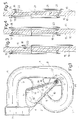
- Figure 1 is a side view in cross section of a unit for supplying combustion air to the cylinders of an endothermic engine produced according to the present invention;
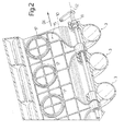
- Figure 2 is a perspective view in cross section of the unit in Figure 1;
- Figure 3 is a view in cross section of a component of the unit in Figure 1;
- Figure 4 is a view in cross section of a variant of the component in Figure 3; and
- Figure 5 is a view in cross section of another variant of the component in Figure 3.
- With reference to Figure 1, 1 denotes the overall unit for supplying combustion air to the cylinders of an endothermic engine not shown in the attached figures.
- The unit 1 comprises a manifold 2 and a series of ducts 3 (Figure 2), each of which is capable of supplying combustion air to a respective cylinder. The manifold 2 has an elongated shape in a direction D1 perpendicular to the plane of the page in Figure 1, while each duct 2 extends along an arcuate path P1 around the direction D1. The manifold 2 has an inlet orifice 4 and two
openings 5 and 6 communicating with theduct 3. Theduct 3 is delimited at the opposite ends thereof by theopening 6 and by an output orifice 7 and has anouter wall 8 and an inner wall 9, along which is arranged theopening 6. - The unit 1 comprises a
bulkhead 10, which is arranged within the manifold 2, is fitted on ashaft 11 and can be rotated about anaxis 12 parallel to the direction 1. - Each opening 5 is delimited by an
edge 13 that rests on a plane A, while eachopening 6 is delimited by an edge 14 that rests on a plane B. Theaxis 12 is arranged in the vicinity of the intersection of the A and of the plane B, such that thebulkhead 10 is capable of coupling both with the openings 5 and with theopenings 6. In theory, if thebulkhead 10 were of zero thickness, theaxis 12 would coincide with the intersection of the planes A and B. - The
bulkhead 10 has afirst face 15 capable of coupling with the openings 5 and asecond face 16 capable of coupling with theopenings 6. Thefaces respective gaskets edges 13 and 14. - As is shown more clearly in Figure 3, the
gaskets respective seats bulkhead 10 and adhesively bonded to thebulkhead 10. - The
gaskets axis 12, as shown in Figure 3, when, as shown in Figure 1, theopenings 5 and 6 are located at different distances from theaxis 12. - In service, each cylinder aspirates the quantity of combustion air required for operation of the engine through the manifold 1. The
bulkhead 10 is displaced by a control member, not shown in the attached figures, from the position shown in solid lines in Figure 1 to the position shown in dashed lines in Figure 1 and vice versa. The control member, which is not shown, performs the above-described displacements as a function of the rotational speed of the engine: at a relatively low rotational speed of the engine and high torque, thebulkhead 10 is placed in the position shown in solid lines corresponding to the "long"supply duct 3; at a high rotational speed and high power, thebulkhead 10 is placed in the position shown in dashed lines corresponding to the "short"supply duct 3. In the above-described positions, thegaskets respective edges 13 and 14. - According to the variant in Figure 2, when the
openings 5 and 6 are located at the same distance from theaxis 12, thegaskets - According to the further variant in Figure 5, the
gaskets bulkhead 10 by the fact that theseats holes 21, and thegaskets holes 21 during the injection moulding phase. In this manner, it is possible to dispense with attaching thegaskets - According to a variant that is not shown, the
bulkhead 10 can be replaced by a series of bulkheads, each of which is of dimensions so as to co-operate with asingle duct 3 or with a group ofducts 3. In fact, the advantage of using thebulkhead 10 or a series of bulkheads resides in the possibility of closing either the opening 5 or the opening 6 without increasing the complexity of the unit 1. From this standpoint, having asingle bulkhead 10 for all thesupply ducts 3 is equivalent to having more mutually aligned bulkheads.
Claims (10)
- Unit (1) for supplying combustion air to the cylinders of an endothermic engine comprises a manifold (2) having an air inlet orifice (4); and at least one supply duct (3) for each cylinder; each supply duct (3) extends between a first opening (5) communicating with the manifold (2) and an outlet orifice (7), and has a second opening (6) arranged between the first opening (5) and the outlet orifice (7); the unit (1) being characterised in that it comprises a bulkhead (10) that can move between the first opening (5) and the second opening (6) in order to close alternately the first opening (5) and the second opening (6).
- Unit according to Claim 1, characterised in that said bulkhead (10) can be rotated about a specific axis (12).
- Unit according to Claim 2, characterised in that the first opening (5) is delimited by a first edge (13) resting on a first plane (A) and that the second opening (6) is delimited by a second edge (14) resting on a second plane (B); the first plane (A) and the second plane (B) intersecting in the vicinity of said specific axis (12).
- Unit according to any one of the preceding claims, characterised in that said bulkhead (10) comprises a first face (15) capable of coupling with the first opening (5) and a second face (16) capable of coupling with the second opening (6).
- Unit according to Claim 4, characterised in that it comprises a first gasket (17) arranged along the first face (15) and a second gasket (18) arranged along the second face (16); the first gasket (17) and the second gasket (18) respectively being capable of coupling with the first edge (13) and the second edge (14).
- Unit according to Claim 5, characterised in that the first gasket (17) and the second gasket (18) are respectively engaged in a first seat (19) and in a second seat (20) of said bulkhead (10).
- Unit according to Claim 6, characterised in that said bulkhead (10) has holes (21) to place the first seat (19) in communication with the second seat (20); said first gasket (17) and second gasket (18) being connected to one another through said holes (21).
- Unit according to Claim 7, characterised that said first gasket (17) and second gasket (18) are simultaneously injection moulded onto said bulkhead (10).
- Unit according to any one of the preceding claims, characterised in that it comprises a plurality of supply ducts (3) and a single bulkhead (10) extending in correspondence with the first openings (5) and the second openings (6) of said supply ducts (3).
- Unit according to any one of Claims 1 to 8, characterised in that it comprises a first number of supply ducts (3) and a second number of bulkheads fitted on a common shaft (11); each bulkhead extending in correspondence with at least one first opening (5) and one second opening (6).
Applications Claiming Priority (2)
| Application Number | Priority Date | Filing Date | Title |
|---|---|---|---|
| IT000362A ITBO20030362A1 (en) | 2003-06-13 | 2003-06-13 | CYLINDER COMBUSTION AIR SUPPLY GROUP |
| ITBO20030362 | 2003-06-13 |
Publications (2)
| Publication Number | Publication Date |
|---|---|
| EP1486651A1 true EP1486651A1 (en) | 2004-12-15 |
| EP1486651B1 EP1486651B1 (en) | 2008-03-19 |
Family
ID=33187365
Family Applications (1)
| Application Number | Title | Priority Date | Filing Date |
|---|---|---|---|
| EP04102646A Expired - Lifetime EP1486651B1 (en) | 2003-06-13 | 2004-06-10 | Unit for supplying combustion air to the cylinders of an endothermic engine |
Country Status (6)
| Country | Link |
|---|---|
| US (1) | US7117837B2 (en) |
| EP (1) | EP1486651B1 (en) |
| BR (1) | BRPI0402333A (en) |
| DE (1) | DE602004012481T2 (en) |
| ES (1) | ES2301936T3 (en) |
| IT (1) | ITBO20030362A1 (en) |
Families Citing this family (2)
| Publication number | Priority date | Publication date | Assignee | Title |
|---|---|---|---|---|
| JP4715784B2 (en) * | 2007-03-15 | 2011-07-06 | トヨタ自動車株式会社 | Gas valve |
| US7975669B2 (en) * | 2009-07-28 | 2011-07-12 | GM Global Technology Operations LLC | Apparatus and method for throttle control of internal combustion engines |
Citations (5)
| Publication number | Priority date | Publication date | Assignee | Title |
|---|---|---|---|---|
| EP0537120A1 (en) * | 1991-10-10 | 1993-04-14 | FIAT AUTO S.p.A. | An intake manifold unit for fuel injection internal combustion engines |
| EP0701057A1 (en) * | 1994-09-09 | 1996-03-13 | Magneti Marelli France | Intake manifold with pivotable flaps for internal combustion engine |
| DE19739424A1 (en) * | 1997-09-09 | 1999-03-11 | Pierburg Ag | Regulator element for air valves in air intake channel system for IC engines |
| EP1211399A2 (en) * | 2000-12-01 | 2002-06-05 | Denso Corporation | Suction device used for internal combustion engine |
| US6406033B1 (en) * | 1997-10-14 | 2002-06-18 | Filterwerk Mann & Hummel Gmbh | Sealing element |
Family Cites Families (4)
| Publication number | Priority date | Publication date | Assignee | Title |
|---|---|---|---|---|
| JP3441614B2 (en) | 1997-04-02 | 2003-09-02 | ダイハツ工業株式会社 | Intake switching device for internal combustion engine |
| JPH10299491A (en) | 1997-04-25 | 1998-11-10 | Aisin Seiki Co Ltd | Intake device for internal combustion engine |
| FR2783283B1 (en) * | 1998-09-14 | 2000-11-24 | Mark Iv Systemes Moteurs Sa | INTEGRATED INTAKE MANIFOLD / BUTTERFLY HOUSING |
| DE19928892A1 (en) | 1999-06-24 | 2000-12-28 | Porsche Ag | Internal combustion engine with fuel injection uses first and second inlet channels and suction and direct injection systems respectively for appropriate operating conditions. |
-
2003
- 2003-06-13 IT IT000362A patent/ITBO20030362A1/en unknown
-
2004
- 2004-06-10 US US10/866,171 patent/US7117837B2/en not_active Expired - Fee Related
- 2004-06-10 DE DE602004012481T patent/DE602004012481T2/en not_active Expired - Lifetime
- 2004-06-10 EP EP04102646A patent/EP1486651B1/en not_active Expired - Lifetime
- 2004-06-10 ES ES04102646T patent/ES2301936T3/en not_active Expired - Lifetime
- 2004-06-14 BR BR0402333-1A patent/BRPI0402333A/en not_active IP Right Cessation
Patent Citations (5)
| Publication number | Priority date | Publication date | Assignee | Title |
|---|---|---|---|---|
| EP0537120A1 (en) * | 1991-10-10 | 1993-04-14 | FIAT AUTO S.p.A. | An intake manifold unit for fuel injection internal combustion engines |
| EP0701057A1 (en) * | 1994-09-09 | 1996-03-13 | Magneti Marelli France | Intake manifold with pivotable flaps for internal combustion engine |
| DE19739424A1 (en) * | 1997-09-09 | 1999-03-11 | Pierburg Ag | Regulator element for air valves in air intake channel system for IC engines |
| US6406033B1 (en) * | 1997-10-14 | 2002-06-18 | Filterwerk Mann & Hummel Gmbh | Sealing element |
| EP1211399A2 (en) * | 2000-12-01 | 2002-06-05 | Denso Corporation | Suction device used for internal combustion engine |
Also Published As
| Publication number | Publication date |
|---|---|
| DE602004012481D1 (en) | 2008-04-30 |
| ITBO20030362A1 (en) | 2004-12-14 |
| ES2301936T3 (en) | 2008-07-01 |
| US20050022773A1 (en) | 2005-02-03 |
| US7117837B2 (en) | 2006-10-10 |
| BRPI0402333A (en) | 2005-05-17 |
| EP1486651B1 (en) | 2008-03-19 |
| DE602004012481T2 (en) | 2009-04-16 |
Similar Documents
| Publication | Publication Date | Title |
|---|---|---|
| JP4706775B2 (en) | Intake device for internal combustion engine | |
| US5875758A (en) | Resin air intake system provided with intake control valve | |
| US7162997B2 (en) | Flap arrangement in the flange area of an intake system for an internal combustion engine | |
| EP0819212B1 (en) | Resin air intake system provided with intake control valve | |
| WO2001054981A3 (en) | Propulsion module | |
| EP3379051B1 (en) | Air intake device for internal combustion engine | |
| US7131416B2 (en) | Engine air intake device | |
| JP4888541B2 (en) | Intake device for internal combustion engine | |
| US6431136B2 (en) | Intake device with ram pipes and longitudinally adjustable resonance pipes | |
| US6732712B2 (en) | Intermediate flange system for an internal combustion engine with direct fuel injection | |
| US8015958B2 (en) | Active intake manifold flap cartridge and method | |
| JP2003120447A (en) | Intake manifold of internal combustion engine and multiple independent intake passage body | |
| US5947082A (en) | Idle air bypass valve silencer | |
| JPS60164619A (en) | Suction device for multicylinder internal-combustion engine | |
| EP1486651B1 (en) | Unit for supplying combustion air to the cylinders of an endothermic engine | |
| US6598585B2 (en) | Variable swirl generating intake manifold with at least one longitudinally oriented partition wall | |
| US6406033B1 (en) | Sealing element | |
| US9556834B2 (en) | Intake system | |
| KR20090115766A (en) | Intake manifold of multi-cylinder internal combustion engine | |
| GB2351771A (en) | Silencer for an idle-air bypass valve in an i.c. engine | |
| US7025029B2 (en) | Air intake tube for an internal combustion engine | |
| JP5910614B2 (en) | Intake control valve and its assembly method | |
| JPH06299919A (en) | Intake pipe of internal combustion engine | |
| US5979389A (en) | Air-intake device having variable induction-pipe length for an internal combustion engine | |
| CN101457707A (en) | Integrally formed engine exhaust manifold and cylinder head |
Legal Events
| Date | Code | Title | Description |
|---|---|---|---|
| PUAI | Public reference made under article 153(3) epc to a published international application that has entered the european phase |
Free format text: ORIGINAL CODE: 0009012 |
|
| AK | Designated contracting states |
Kind code of ref document: A1 Designated state(s): AT BE BG CH CY CZ DE DK EE ES FI FR GB GR HU IE IT LI LU MC NL PL PT RO SE SI SK TR |
|
| AX | Request for extension of the european patent |
Extension state: AL HR LT LV MK |
|
| 17P | Request for examination filed |
Effective date: 20050610 |
|
| AKX | Designation fees paid |
Designated state(s): DE ES FR GB SE |
|
| GRAP | Despatch of communication of intention to grant a patent |
Free format text: ORIGINAL CODE: EPIDOSNIGR1 |
|
| GRAS | Grant fee paid |
Free format text: ORIGINAL CODE: EPIDOSNIGR3 |
|
| GRAA | (expected) grant |
Free format text: ORIGINAL CODE: 0009210 |
|
| AK | Designated contracting states |
Kind code of ref document: B1 Designated state(s): DE ES FR GB SE |
|
| REG | Reference to a national code |
Ref country code: GB Ref legal event code: FG4D |
|
| REF | Corresponds to: |
Ref document number: 602004012481 Country of ref document: DE Date of ref document: 20080430 Kind code of ref document: P |
|
| REG | Reference to a national code |
Ref country code: SE Ref legal event code: TRGR |
|
| REG | Reference to a national code |
Ref country code: ES Ref legal event code: FG2A Ref document number: 2301936 Country of ref document: ES Kind code of ref document: T3 |
|
| ET | Fr: translation filed | ||
| PLBE | No opposition filed within time limit |
Free format text: ORIGINAL CODE: 0009261 |
|
| STAA | Information on the status of an ep patent application or granted ep patent |
Free format text: STATUS: NO OPPOSITION FILED WITHIN TIME LIMIT |
|
| 26N | No opposition filed |
Effective date: 20081222 |
|
| PGFP | Annual fee paid to national office [announced via postgrant information from national office to epo] |
Ref country code: ES Payment date: 20090616 Year of fee payment: 6 |
|
| PGFP | Annual fee paid to national office [announced via postgrant information from national office to epo] |
Ref country code: SE Payment date: 20090618 Year of fee payment: 6 |
|
| PGFP | Annual fee paid to national office [announced via postgrant information from national office to epo] |
Ref country code: GB Payment date: 20090602 Year of fee payment: 6 |
|
| EUG | Se: european patent has lapsed | ||
| GBPC | Gb: european patent ceased through non-payment of renewal fee |
Effective date: 20100610 |
|
| REG | Reference to a national code |
Ref country code: ES Ref legal event code: FD2A Effective date: 20110715 |
|
| PG25 | Lapsed in a contracting state [announced via postgrant information from national office to epo] |
Ref country code: GB Free format text: LAPSE BECAUSE OF NON-PAYMENT OF DUE FEES Effective date: 20100610 Ref country code: ES Free format text: LAPSE BECAUSE OF NON-PAYMENT OF DUE FEES Effective date: 20110705 |
|
| PG25 | Lapsed in a contracting state [announced via postgrant information from national office to epo] |
Ref country code: ES Free format text: LAPSE BECAUSE OF NON-PAYMENT OF DUE FEES Effective date: 20100611 |
|
| PG25 | Lapsed in a contracting state [announced via postgrant information from national office to epo] |
Ref country code: SE Free format text: LAPSE BECAUSE OF NON-PAYMENT OF DUE FEES Effective date: 20100611 |
|
| REG | Reference to a national code |
Ref country code: FR Ref legal event code: PLFP Year of fee payment: 12 |
|
| PGFP | Annual fee paid to national office [announced via postgrant information from national office to epo] |
Ref country code: DE Payment date: 20150521 Year of fee payment: 12 |
|
| PGFP | Annual fee paid to national office [announced via postgrant information from national office to epo] |
Ref country code: FR Payment date: 20150526 Year of fee payment: 12 |
|
| REG | Reference to a national code |
Ref country code: DE Ref legal event code: R119 Ref document number: 602004012481 Country of ref document: DE |
|
| REG | Reference to a national code |
Ref country code: FR Ref legal event code: ST Effective date: 20170228 |
|
| PG25 | Lapsed in a contracting state [announced via postgrant information from national office to epo] |
Ref country code: FR Free format text: LAPSE BECAUSE OF NON-PAYMENT OF DUE FEES Effective date: 20160630 Ref country code: DE Free format text: LAPSE BECAUSE OF NON-PAYMENT OF DUE FEES Effective date: 20170103 |