EP1486573B1 - Process and device for cooling a moving metallic strip - Google Patents
Process and device for cooling a moving metallic strip Download PDFInfo
- Publication number
- EP1486573B1 EP1486573B1 EP03291389A EP03291389A EP1486573B1 EP 1486573 B1 EP1486573 B1 EP 1486573B1 EP 03291389 A EP03291389 A EP 03291389A EP 03291389 A EP03291389 A EP 03291389A EP 1486573 B1 EP1486573 B1 EP 1486573B1
- Authority
- EP
- European Patent Office
- Prior art keywords
- strip
- roller
- cooling
- support roller
- principal
- Prior art date
- Legal status (The legal status is an assumption and is not a legal conclusion. Google has not performed a legal analysis and makes no representation as to the accuracy of the status listed.)
- Expired - Lifetime
Links
- 238000001816 cooling Methods 0.000 title claims abstract description 94
- 238000000034 method Methods 0.000 title claims abstract description 15
- 238000009434 installation Methods 0.000 claims abstract description 33
- 239000000463 material Substances 0.000 claims abstract description 19
- 229920001971 elastomer Polymers 0.000 claims description 11
- 239000000806 elastomer Substances 0.000 claims description 11
- 230000002093 peripheral effect Effects 0.000 claims description 5
- 239000012530 fluid Substances 0.000 claims description 2
- 229910052710 silicon Inorganic materials 0.000 claims 1
- 239000010703 silicon Substances 0.000 claims 1
- 239000002184 metal Substances 0.000 abstract description 9
- 238000012546 transfer Methods 0.000 description 5
- 229910000831 Steel Inorganic materials 0.000 description 3
- 238000000576 coating method Methods 0.000 description 3
- 235000021183 entrée Nutrition 0.000 description 3
- 229920001296 polysiloxane Polymers 0.000 description 3
- 239000003507 refrigerant Substances 0.000 description 3
- 239000010959 steel Substances 0.000 description 3
- 238000012360 testing method Methods 0.000 description 3
- 238000000137 annealing Methods 0.000 description 2
- 239000007788 liquid Substances 0.000 description 2
- 238000012423 maintenance Methods 0.000 description 2
- 238000011282 treatment Methods 0.000 description 2
- XLYOFNOQVPJJNP-UHFFFAOYSA-N water Substances O XLYOFNOQVPJJNP-UHFFFAOYSA-N 0.000 description 2
- 238000004804 winding Methods 0.000 description 2
- 238000009825 accumulation Methods 0.000 description 1
- 230000015572 biosynthetic process Effects 0.000 description 1
- 238000009529 body temperature measurement Methods 0.000 description 1
- 230000015556 catabolic process Effects 0.000 description 1
- 229910010293 ceramic material Inorganic materials 0.000 description 1
- 239000011248 coating agent Substances 0.000 description 1
- 230000000295 complement effect Effects 0.000 description 1
- 239000000498 cooling water Substances 0.000 description 1
- 238000006731 degradation reaction Methods 0.000 description 1
- 230000001419 dependent effect Effects 0.000 description 1
- 230000000694 effects Effects 0.000 description 1
- 239000013013 elastic material Substances 0.000 description 1
- 238000005516 engineering process Methods 0.000 description 1
- 238000005246 galvanizing Methods 0.000 description 1
- 239000013529 heat transfer fluid Substances 0.000 description 1
- 238000010438 heat treatment Methods 0.000 description 1
- 239000010410 layer Substances 0.000 description 1
- 238000004519 manufacturing process Methods 0.000 description 1
- 229910001092 metal group alloy Inorganic materials 0.000 description 1
- 238000007747 plating Methods 0.000 description 1
- 238000010791 quenching Methods 0.000 description 1
- 230000000171 quenching effect Effects 0.000 description 1
- 239000002344 surface layer Substances 0.000 description 1
- 238000001931 thermography Methods 0.000 description 1
- 238000012549 training Methods 0.000 description 1
- 238000011144 upstream manufacturing Methods 0.000 description 1
- 238000009489 vacuum treatment Methods 0.000 description 1
Images


Classifications
-
- C—CHEMISTRY; METALLURGY
- C21—METALLURGY OF IRON
- C21D—MODIFYING THE PHYSICAL STRUCTURE OF FERROUS METALS; GENERAL DEVICES FOR HEAT TREATMENT OF FERROUS OR NON-FERROUS METALS OR ALLOYS; MAKING METAL MALLEABLE, e.g. BY DECARBURISATION OR TEMPERING
- C21D9/00—Heat treatment, e.g. annealing, hardening, quenching or tempering, adapted for particular articles; Furnaces therefor
- C21D9/52—Heat treatment, e.g. annealing, hardening, quenching or tempering, adapted for particular articles; Furnaces therefor for wires; for strips ; for rods of unlimited length
- C21D9/54—Furnaces for treating strips or wire
- C21D9/56—Continuous furnaces for strip or wire
- C21D9/573—Continuous furnaces for strip or wire with cooling
- C21D9/5735—Details
- C21D9/5737—Rolls; Drums; Roll arrangements
-
- C—CHEMISTRY; METALLURGY
- C21—METALLURGY OF IRON
- C21D—MODIFYING THE PHYSICAL STRUCTURE OF FERROUS METALS; GENERAL DEVICES FOR HEAT TREATMENT OF FERROUS OR NON-FERROUS METALS OR ALLOYS; MAKING METAL MALLEABLE, e.g. BY DECARBURISATION OR TEMPERING
- C21D9/00—Heat treatment, e.g. annealing, hardening, quenching or tempering, adapted for particular articles; Furnaces therefor
- C21D9/52—Heat treatment, e.g. annealing, hardening, quenching or tempering, adapted for particular articles; Furnaces therefor for wires; for strips ; for rods of unlimited length
- C21D9/54—Furnaces for treating strips or wire
- C21D9/56—Continuous furnaces for strip or wire
- C21D9/573—Continuous furnaces for strip or wire with cooling
Landscapes
- Chemical & Material Sciences (AREA)
- Engineering & Computer Science (AREA)
- Materials Engineering (AREA)
- Thermal Sciences (AREA)
- Crystallography & Structural Chemistry (AREA)
- Mechanical Engineering (AREA)
- Physics & Mathematics (AREA)
- Metallurgy (AREA)
- Organic Chemistry (AREA)
- Heat Treatment Of Strip Materials And Filament Materials (AREA)
- Rolls And Other Rotary Bodies (AREA)
- Extrusion Moulding Of Plastics Or The Like (AREA)
- Heat Treatments In General, Especially Conveying And Cooling (AREA)
- Continuous Casting (AREA)
Abstract
Description
La présente invention concerne un procédé et une installation de refroidissement d'une bande métallique en défilement.The present invention relates to a method and a cooling installation of a metal strip in scrolling.
Elle s'applique notamment aux traitements sous vide d'une telle bande, en particulier aux revêtements à chaud.It applies in particular to vacuum treatments such a strip, in particular to hot coatings.
Pour mener à bien des opérations de traitements thermiques, tels que des recuits ou des revêtements continus, d'une bande d'acier, il est généralement nécessaire de successivement chauffer et refroidir la bande, avec des vitesses prédéterminées. Pour refroidir une telle bande de manière contrôlée, on trempe la bande soit par un jet de gaz, soit par un jet de liquide, soit par au moins un rouleau de refroidissement sur lequel la bande vient en contact.To carry out treatment operations thermal, such as annealing or coatings continuous, of a steel strip, it is usually necessary to successively heat and cool the band, with predetermined speeds. To cool a such strip in a controlled manner, the strip is tempered either by a jet of gas, either by a jet of liquid, or by minus a cooling roll on which the band comes in contact.
Les procédés connus de refroidissement par rouleau consistent à appliquer une bande qui se déplace suivant un mouvement continu sur au moins un rouleau de refroidissement à l'intérieur duquel circule un liquide réfrigérant, notamment de l'eau froide. Le rouleau est mobile en rotation autour de son axe, en étant entraíné soit par le frottement de la bande en défilement, soit par un ensemble motorisé propre. La bande ainsi appliquée sur le rouleau forme un arc dont l'intrados délimite avec la face extérieure du rouleau une zone de contact adaptée pour évacuer vers l'intérieur du rouleau une partie de la chaleur de la bande. Le document JP-A-60 255 933 décrit un procédé et une installation de refroidissement d'une bande d'acier en défilement pendant le recuit continu ou la galvanisation.Known methods of cooling by roll consist of applying a tape that moves in a continuous movement on at least one roll of cooling inside which circulates a liquid refrigerant, especially cold water. The roll is mobile in rotation about its axis, being driven either by the friction of the moving strip or by a motorized set clean. The band thus applied on the roll forms an arc whose intrados delimits with the outer surface of the roller a contact zone adapted for evacuate towards the inside of the roll part of the heat of the band. JP-A-60 255 933 discloses a method and an installation cooling of a scrolling steel strip during the continuous annealing or galvanizing.
Pour améliorer le contact entre la bande et le rouleau de refroidissement, on a proposé par le passé de maintenir l'arc de bande en contact avec le rouleau au moyen de rouleaux métalliques d'appui sur l'extrados de l'arc. Pour garantir le maintien d'un effet de plaquage de la bande sur le rouleau de refroidissement, chacun de ces rouleaux d'appui est monté à rotation libre autour de son axe, à l'extrémité de bras rigides, dont l'éloignement par rapport au rouleau de refroidissement est prédéterminé en fonction de l'épaisseur de la bande.To improve the contact between the tape and the roll in the past, it has been proposed to maintain the arc of tape in contact with the roll by means of metal support rollers on the upper surface of the arc. For guarantee the maintenance of a plating effect of the band on the cooling roll, each of these rollers support is mounted for free rotation around its axis, the end of rigid arms, whose distance from to the cooling roll is predetermined in function of the thickness of the band.
Bien que de tels rouleaux d'appui métalliques génèrent le maintien escompté de la bande sur le rouleau de refroidissement, ils font courir le risque d'une part de marquer l'extrados de la bande, ce marquage pouvant être très profond en cas de défaut de parallélisme des axes du rouleau de refroidissement et des rouleaux d'appui, et d'autre part de perturber le refroidissement de la bande en raison de la rapide accumulation de chaleur dans les rouleaux d'appui.Although such metal backup rolls generate the expected maintenance of the tape on the roll of cooling, they run the risk of a share of mark the upper surface of the band, this marking being very deep in case of lack of parallelism of the axes of the cooling roll and backup rollers, and on the other hand to disturb the cooling of the band in because of the rapid accumulation of heat in the support rollers.
Le but de la présente invention est de proposer un procédé et une installation de refroidissement d'une bande métallique en défilement, qui permettent de maintenir fermement la bande contre un rouleau de refroidissement, tout en contrôlant ce refroidissement et sans pour autant nuire à l'état de surface de la bande.The object of the present invention is to propose a process and a cooling installation of a band metallic scrolling, which allow to maintain firmly tape against a cooling roll, while controlling this cooling and without impair the surface condition of the strip.
A cet effet, l'invention a pour objet un procédé de refroidissement d'une bande métallique en défilement, du type dans lequel :
- on déplace en continu la bande métallique à refroidir,
- on applique la bande sur un rouleau de refroidissement principal mobile autour de son axe de façon à ce que la bande forme un arc dont l'intrados délimite avec la face extérieure du rouleau de refroidissement principal une zone de contact adaptée pour évacuer vers l'intérieur de ce rouleau une partie de la chaleur de la bande, et
- on maintient la bande en contact avec le rouleau de refroidissement principal au moyen d'au moins un rouleau d'appui sur l'extrados de l'arc formé par la bande, le ou chaque rouleau d'appui étant disposé sensiblement parallèlement au rouleau de refroidissement principal et mobile en rotation autour de son axe,
- the metal strip to be cooled is continuously moved,
- the strip is applied to a main cooling roll movable about its axis so that the band forms an arc whose intrados delimits with the outer face of the main cooling roll a contact zone adapted to evacuate inwards from this roll some of the heat of the band, and
- the strip is held in contact with the main cooling roller by means of at least one support roller on the extrados of the arc formed by the strip, the or each support roller being arranged substantially parallel to the roller of main cooling and mobile in rotation about its axis,
Suivant d'autres caractéristiques de ce procédé, prises isolément ou selon toutes les combinaisons techniquement possibles :
- le ou chaque rouleau d'appui s'étend sur au moins toute la largeur de la bande de façon à appliquer sur l'extrados de l'arc formé par la bande une pression sensiblement homogène sur toute cette largeur ;
- la température de la bande appliquée en entrée du rouleau de refroidissement principal est inférieure à la température de dégradation de la matière constituant le ou les rouleaux d'appui ; et
- la température de la bande appliquée en entrée est inférieure à environ 200°C.
- the or each support roller extends over at least the entire width of the strip so as to apply on the extrados of the arc formed by the band a substantially homogeneous pressure over the entire width;
- the temperature of the strip applied at the inlet of the main cooling roll is less than the degradation temperature of the material constituting the at least one supporting roll; and
- the temperature of the input band is less than about 200 ° C.
L'invention a également pour objet une installation de refroidissement d'une bande métallique en défilement, ladite bande à refroidir étant déplacée en continu, du type comportant un rouleau de refroidissement principal sur lequel est appliquée la bande de façon à former un arc dont l'intrados délimite avec la face extérieure de ce rouleau une zone de contact adaptée pour évacuer vers l'intérieur du rouleau de refroidissement principal une partie de la chaleur de la bande, et au moins un rouleau d'appui sur l'extrados de l'arc formé par la bande, adapté pour maintenir la bande en contact sur le rouleau de refroidissement principal, le ou chaque rouleau d'appui étant disposé sensiblement parallèlement au rouleau de refroidissement principal et mobile en rotation autour de son axe, caractérisée en ce que le ou chaque rouleau d'appui est constitué, au moins en périphérie, d'une matière élastiquement déformable et thermo-capacitive, et en ce que l'installation comporte des moyens de refroidissement secondaire adaptés pour former avec une partie de la face externe du ou de chaque rouleau d'appui une zone de transfert de chaleur vers ces moyens de refroidissement secondaire en vue d'évacuer la chaleur transmise de la bande à le ou chaque rouleau d'appui.The subject of the invention is also a plant of cooling a scrolling metal strip, said strip to be cooled being moved continuously, of the type having a main cooling roll on which the band is applied to form an arc whose the intrados demarcates with the outside face of this roll a contact zone adapted to evacuate inwards of the main cooling roll part of the heat of the tape, and at least one backup roll on the extrados of the arc formed by the strip, adapted for keep the tape in contact on the roll of main cooling, the or each support roll being disposed substantially parallel to the roll of main and mobile cooling in rotation around its axis, characterized in that the or each roller of support is constituted, at least at the periphery, of a an elastically deformable and thermo-capacitive material, and in that the installation comprises means for secondary cooling adapted to form with a part of the outer face of the or each support roll a zone of heat transfer to these means of secondary cooling to remove heat transmitted from the tape to the or each backup roll.
Selon d'autres caractéristiques de cette installation, prises isolément ou selon toutes les combinaisons techniquement possibles :
- le ou chaque rouleau d'appui est réalisé, au moins en périphérie, en élastomère, notamment en silicone vulcanisé ;
- la matière dont est constitué au moins en périphérie le ou chaque rouleau d'appui, possède un coefficient de conductibilité thermique inférieur à 1 W/m.K ;
- le diamètre du ou de chaque rouleau d'appui est compris entre un quart et un dixième du diamètre du rouleau de refroidissement principal ;
- les moyens de refroidissement secondaire comportent au moins un rouleau de refroidissement secondaire mobile en rotation autour de son axe et disposé sensiblement parallèlement aux rouleaux d'appui ; et
- l'installation comporte des moyens d'alimentation avec un fluide caloporteur, communs au rouleau de refroidissement principal et aux moyens de refroidissement secondaire.
- the or each backing roll is made, at least peripherally, of elastomer, in particular vulcanized silicone;
- the material which is formed at least peripherally the or each support roller, has a coefficient of thermal conductivity of less than 1 W / mK;
- the diameter of the or each backing roll is between a quarter and a tenth of the diameter of the main cooling roll;
- the secondary cooling means comprise at least one secondary cooling roller movable in rotation about its axis and disposed substantially parallel to the support rollers; and
- the installation comprises supply means with a heat transfer fluid, common to the main cooling roller and the secondary cooling means.
L'invention sera mieux comprise à la lecture de la description qui va suivre, donnée uniquement à titre d'exemple et faite en se référant aux dessins sur lesquels :
- la figure 1 est une vue schématique d'une installation de refroidissement selon l'invention ;
- les figures 2 et 3 sont des vues analogues à la figure 1, illustrant deux variantes de l'installation selon l'invention.
- Figure 1 is a schematic view of a cooling system according to the invention;
- Figures 2 and 3 are views similar to Figure 1, illustrating two variants of the installation according to the invention.
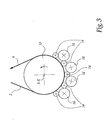
L'installation 1 représentée sur la figure 1 est
destinée à refroidir une bande d'acier 2, défilant suivant
le sens indiqué par les flèches 4. Cette installation est
par exemple utilisée lors de traitements de revêtements de
la bande, notamment sous vide.The
Cette installation comporte :
- deux cylindres 8A et 8B de déflection de la
bande 2, pourvus éventuellement d'un système motorisé d'entraínement non représenté ; - un
rouleau 10 de refroidissement principal, d'axe X-X et agencé vis-à-vis des cylindres déflecteurs 8A et 8B de façon à ce que ces derniers guident labande 2 de manière adéquate, respectivement en entrée et en sortie durouleau 10 ; - un
rouleau 14 d'appui de la bande sur le rouleau derefroidissement 10, d'axe Z-Z sensiblement parallèle à l'axe X-X durouleau 10 et de préférence disposé sensiblement à l'aplomb de la zone d'enroulement de la bande autour durouleau 10 ; et - un
rouleau 16 de refroidissement secondaire, d'axe X'-X' parallèle à l'axe Z-Z desrouleaux 14, disposé en contact avec cesrouleaux 14 du côté opposé à celui durouleau 10, un même plan P formant des plans médians pour lesrouleaux 10 et 16.
- two rollers 8A and 8B deflection of the
band 2, optionally provided with a motorized drive system not shown; - a
main cooling roll 10, of axis XX and arranged vis-à-vis the deflector rollers 8A and 8B so that the latter guide thestrip 2 adequately, respectively at the inlet and at the outlet of theroll 10; - a
roll 14 for supporting the strip on thecooling roll 10, ZZ axis substantially parallel to the axis XX of theroll 10 and preferably disposed substantially above the winding zone of the strip around theroll 10; and - a
secondary cooling roll 16, of axis X'-X 'parallel to the axis ZZ of therollers 14, disposed in contact with theserollers 14 on the opposite side to that of theroll 10, the same plane P forming median planes for therollers
Plus précisément, le rouleau de refroidissement
principal 10 et le rouleau de refroidissement secondaire 16
sont à même d'évacuer des calories depuis leur face
extérieure vers l'intérieur des rouleaux lorsqu'un corps
chaud est appliqué sur eux. A cet effet, les rouleaux 10 et
16 comportent, de manière connue, une double enveloppe
permettant de faire circuler en périphérie interne de ces
rouleaux un fluide réfrigérant, tel que de l'eau froide.
D'autres types de rouleau de refroidissement par contact,
connus par l'homme du métier, sont envisageables.Specifically, the cooling roll
main 10 and the
Le rouleau d'appui 14 quant à lui formé d'une pièce
monobloc cylindrique d'axe Z-Z ou d'un empilement de
cylindres coaxiaux de faible épaisseur dépendants ou non.
Le rouleau 14 est réalisé en une matière élastiquement
déformable, notamment en élastomère. Pour la présente
invention, l'expression «matière élastiquement déformable»
est à considérer comme désignant de manière générale un
matériau dont le module d'élasticité (ou module de Young)
est nettement plus faible que celui du matériau formant la
bande 2, pour des raisons développées plus loin. A titre
d'exemple d'un élastomère approprié, on peut citer un
silicone vulcanisé. The
La matière constituant le rouleau d'appui 14 présente
en outre des propriétés de conductibilité et de capacité
thermiques préférées, à savoir qu'elle ne doit pas être
totalement ou quasiment totalement résistante à la
conduction de la chaleur, comme pourrait l'être par exemple
un matériau céramique, mais ne doit pas non plus
nécessairement assurer une conduction importante comme un
alliage métallique courant. Elle doit en outre pouvoir
stocker en son sein l'énergie thermique soutirée à la
bande. L'élastomère dont est constitué le rouleau d'appui
14 possède par exemple un coefficient de conductibilité
thermique inférieur à environ 1 W/m.K (watt par mètre et
par Kelvin) et une capacité calorifique élevée, par exemple
de l'ordre de 1000 J/kg.K (joule par kilogramme et par
Kelvin).The material constituting the
Le diamètre du rouleau 14 est de préférence compris
entre un quart et un dixième du diamètre du rouleau 10. De
plus, la longueur de ce rouleau 14 est au moins légèrement
supérieure à la largeur de la bande 2.The diameter of the
Le fonctionnement de l'installation 1, qui illustre le
procédé selon l'invention, est le suivant :The operation of the
La bande 2, provenant en amont de l'installation 1
d'une installation attenante de production, d'une bobine ou
d'une installation de chauffage non représentées, arrive en
entrée de l'installation 1 à une température considérée
comme chaude, comprise notamment entre la température
ambiante et une température haute au-delà de laquelle la
matière constituant le rouleau d'appui 14 risque d'être
dégradée, c'est-à-dire par exemple entre la température
ambiante et environ 200°C. Son entraínement peut être au
moins partiellement assuré par le cylindre 8A.
La bande 2 est, en sortie du cylindre 8A, appliquée
sur le rouleau de refroidissement principal 10, autour
duquel la bande forme un arc le plus grand possible, par
exemple de 240° environ, dont l'intrados est en contact
avec la face extérieure du cylindre 10. Lors de son
application sur le rouleau 10, l'arc formé par la bande 2
est, de préférence dans sa zone de début d'enroulement,
maintenu en contact pressé sur ce rouleau par les rouleaux
d'appui 14.The
La position relative du rouleau 14 par rapport à la
surface extérieure du rouleau 10 est soit pré-réglée,
notamment en fonction de l'épaisseur de la bande 2, soit
commandée par des moyens de support élastiquement
déformables de façon à ce que l'extrados de la bande 2 soit
soumise à une pression de contact suffisante pour aplanir
la bande suivant sa largeur et pour favoriser le transfert
de chaleur de la bande au rouleau de refroidissement 10 en
augmentant la surface de contact entre l'intrados de cette
bande et la face extérieure de ce rouleau.The relative position of the
La faible rigidité de la matière formant les rouleaux
d'appui limite les risques de marquage de l'extrados de la
bande, même dans le cas où existe un défaut de parallélisme
entre les axes Z-Z et X-X. De plus, la bande 2 présente
alors une bonne planéité transversale.The low rigidity of the material forming the rollers
support limits the risk of marking the upper surface of the
band, even in the case where there is a lack of parallelism
between the Z-Z and X-X axes. In addition,
En outre, la matière formant les rouleaux d'appui 14
étant thermo-capacitive, une partie de la chaleur de la
bande est transférée de la bande au rouleau d'appui,
assurant ainsi un refroidissement complémentaire de la
bande.In addition, the material forming the
Le défilement de la bande 2 entraíne le rouleau
d'appui 14 en rotation autour de son axe, ce rouleau 14
entraínant lui-même le rouleau de refroidissement
secondaire 16. La zone de contact que maintient le rouleau
d'appui 14 avec le rouleau 16 permet le transfert de
chaleur depuis la partie périphérique du rouleau 14 jusqu'à
l'intérieur du rouleau 16. Comme la matière formant les
rouleaux d'appui est fortement thermo-capacitive, la
chaleur transférée de la bande au rouleau d'appui 14 est
stockée en périphérie du rouleau 14 avant d'être à son tour
transférée aux rouleaux de refroidissement 16.Scrolling the
L'élasticité de la matière formant le rouleau d'appui
14 assure, même en cas de manque de parallélisme entre les
axes Z-Z et X' -X', la formation d'une grande surface de
contact entre le rouleau 14 et la face extérieur du rouleau
16, et donc un bon transfert calorifique.The elasticity of the material forming the
En sortie du rouleau 10, la bande 2 s'enroule autour
du cylindre déflecteur 8B et sort de l'installation 1.At the exit of the
Le procédé selon l'invention permet ainsi de refroidir
de manière contrôlée la bande 2, sans endommager ni marquer
ses surfaces. Le refroidissement obtenu est à la fois
homogène, assurant par là l'homogénéité des qualités de la
bande refroidie, et rapide, ce qui permet de réduire la
durée du refroidissement et ainsi la longueur de la zone
correspondante.The method according to the invention thus makes it possible to cool
in a controlled way the
L'utilisation d'élastomère pour former les rouleaux
d'appui 14 est peu onéreuse et le rouleau de
refroidissement secondaire 16 relève d'une technologie déjà
existante. D'ailleurs, le réseau de circulation du fluide
réfrigérant envoyé au rouleau de refroidissement principal
10 peut avantageusement être utilisé, par exemple au moyen
de dérivations, pour alimenter le rouleau de
refroidissement secondaire 16. En d'autres termes, à partir
d'une installation de refroidissement pré-existante, le
coût d'investissement pour disposer d'une installation
selon l'invention est minime.The use of elastomer to form the
Sur la figure 2 est représentée une variante de
l'installation 1 qui se distingue de celle de la figure 1
par, d'une part, la mise en place, entre le rouleau de
refroidissement principal 10 et le rouleau de
refroidissement secondaire 16, de deux rouleaux d'appui 14
au lieu d'un, et, d'autre part, le remplacement du cylindre
déflecteur de sortie 8B par un deuxième cylindre de
refroidissement principal 12, par exemple analogue au
rouleau 10. Le fonctionnement de cette installation est
sensiblement analogue à celui de la figure 1.FIG. 2 shows a variant of
the
Des exemples de mises en oeuvre de procédés selon l'art
antérieur et selon l'invention avec l'installation 1 de la
figure 2 sont détaillés ci-dessous. Dans les deux tableaux
ci-après sont résumés les paramètres de fonctionnement de
cette installation :

Dans le tableau ci-après sont résumés des résultats
d'essais :

Les essais 1 et 2 sont réalisés sans aucun rouleau
d'appui, tandis que les essais 3 et 4 sont réalisés avec
les deux rouleaux d'appui 14 en élastomère comme représenté
sur la figure 2.
On constate une efficacité de refroidissement quinze
fois plus importante sur le premier rouleau de
refroidissement principal 10 lorsque celui-ci est associé
aux deux rouleaux d'appui 14, mais également une
augmentation sensible sur le second rouleau de
refroidissement 12. ces résultats traduisent le fait que
les rouleaux d'appui 14 rendent une bonne planéité
transversale à la bande 2, permettant un refroidissement
important et homogène sur la largeur de la bande. Des
mesures de température par thermographie infra-rouge
confirment d'ailleurs que le refroidissement de température
est bien homogène.There is a cooling efficiency fifteen
times more important on the first roll of
Par ailleurs, concernant la température atteinte par
les rouleaux d'appui 14, on a pu déterminer que,
localement, la couche superficielle de matière des rouleaux
14 peut atteindre pendant un temps assez court, de l'ordre
de la durée du contact, la température de la bande 2 avec
laquelle ces rouleaux sont en contact. C'est surtout le cas
lorsque la vitesse de défilement de la bande est faible,
par exemple de l'ordre de 20 m/min pour l'exemple de mise
en oeuvre détaillé dans les tableaux 1 et 2 ci-dessus.Moreover, concerning the temperature reached by
the
Cependant, lorsque la vitesse de défilement de la bande augmente, la durée de contact de l'élastomère sur la bande ne suffit pas pour que l'échange de chaleur soit complet, la température de l'élastomère restant alors inférieure à celle de la bande. Ainsi, pour une vitesse de défilement de l'ordre de 150 m/min, ce qui correspond à une vitesse de défilement pour une installation industrielle, et pour une température d'entrée de la bande de l'ordre de 150°C, l'élastomère atteint localement au maximum une température de l'ordre de 100°C, ce qui correspond à une température de service courante pour la plupart des élastomères vulcanisés.However, when the scroll speed of the band increases, the contact time of the elastomer on the band is not sufficient for the heat exchange to be complete, the temperature of the elastomer remaining then less than that of the band. So, for a speed of scrolling of the order of 150 m / min, which corresponds to a scroll speed for an industrial installation, and for an input temperature of the band of the order of 150 ° C, the elastomer locally reaches a maximum of one temperature of the order of 100 ° C, which corresponds to a current service temperature for most vulcanized elastomers.
Divers aménagements et variantes au procédé et à
l'installation décrits ci-dessus sont envisageables. En
particulier, Le nombre de rouleaux d'appui et de rouleaux
de refroidissement secondaire, leurs dimensions, ainsi que
leur agencement ne sont limités que par l'espace libre
disponible autour du rouleau de refroidissement principal
considéré. Toute combinaison est possible, pour autant que
chaque rouleau d'appui soit refroidi par au moins un
rouleau secondaire. A titre d'exemple, la figure 3
représente un rouleau de refroidissement principal 10
associé à cinq rouleaux d'appui 14 et à quatre rouleaux de
refroidissement secondaire 16.Various arrangements and variants of the process and
the installation described above are possible. In
The number of support rollers and rollers
secondary cooling, their dimensions, as well as
their layout is limited only by the free space
available around the main cooling roll
considered. Any combination is possible, provided that
each backing roll is cooled by at least one
secondary roller. For example, Figure 3
represents a
En outre, le ou les rouleaux d'appui 14 peuvent
comporter une structure multicouches, seules la et/ou les
couches externes devant posséder les caractéristiques de
souplesse et de capacité thermique détaillées plus haut
pour réaliser l'invention.In addition, the support roller or
Par ailleurs, le rouleau de refroidissement 16 est
remplaçable par d'autres moyens de refroidissement
secondaire, tels que des systèmes à trempe par jet de gaz
tant que ces moyens forment avec une partie de la face
externe des rouleaux d'appui une zone suffisante
d'évacuation de chaleur.Moreover, the cooling
Claims (10)
- Procedure for cooling a running metallic strip, of the type in which:characterised in that the support roller or each support roller (14) consists, at least in its peripheral sections, of a thermo-capacitive material capable of elastic distortion, and in that the heat transmitted from the strip (2) is removed into the or each support roller (14) by secondary cooling means (16) adapted to produce a zone for transferring heat towards these secondary cooling means (16) by combining with the outer face of the or each support roller (14).the metallic strip (2) to be cooled runs continuously,the band (2) is applied to a principal cooling roller (10) that is mobile about its axis (X-X) so that the strip forms an arc the intrados of which combines with the outer face of the principal cooling strip to produce a zone of contact suitable for removing part of the heat from the strip to the interior of the roller,the strip (2) is also kept in contact with the principal cooling roller (10) by means of at least one support roller (14) on the extrados of the arc formed by the strip. The position of this support roller (or of each support roller) is clearly parallel to the principal cooling roller (10) and the roller(s) is/are mobile about its/their axis Z-Z,
- Procedure according to Claim 1, characterised in that the or each support roller (14) extends at least right across the width of the strip (2) so that sufficiently homogeneous pressure is applied right across that width to the extrados of the arc formed by the strip.
- Procedure according to Claim 1 or 2, characterised in that the temperature of the strip (2) applied on entry to the principal cooling roller (10) is less than the temperature at which the material making up the support roller(s) (14) begins to suffer damage.
- Procedure according to Claim 3, characterised in that the said temperature of the strip applied on entry is less than about 200°C.
- Cooling installation for a running metallic strip, with the strip (2) to be cooled running continuously through a device containing a principal cooling roller (10) to which the strip (2) is applied so as to form an arc the intrados of which combines with the outer face of the roller (10) to produce a zone of contact suitable for removing part of the heat from the strip to the interior of the roller, and at least one support roller (14) on the extrados of the arc formed by the strip, adapted to keep the strip in contact with the principal cooling roller (10), the position of the or each support roller being clearly parallel to the principal cooling roller and mobile about its axis Z-Z, characterised in that the support roller (14) consists, at least in its peripheral sections, of a thermo-capacitive material capable of elastic distortion, and in that the installation (1) contains secondary cooling means (16) adapted to produce, together with the outer face of the or each support roller (14) a zone for transferring heat into these secondary cooling means, with the aim of removing the heat transmitted from the strip (2) to the support roller or each support roller.
- Installation according to Claim 5, characterised in that the or each support roller (14) consists, at least in its peripheral sections, of an elastomer, most notably vulcanised silicon.
- Installation according to Claim 5 or 6, characterised in that the material of which at least the peripheral sections of the or each support roller (14) consist, has a heat conductivity coefficient of less than 1 W/m.K.
- Installation according to any of Claims 5-7, characterised in that the diameter of the or each support roller (14) is between one quarter and one tenth of the diameter of the principal cooling roller (10).
- Installation according to any of Claims 5-8, characterised in that the secondary cooling means contain at least one secondary cooling roller (16) mobile about its axis X'-X' and clearly positioned parallel to the support roller(s) (14).
- Installation according to any of Claims 5-9, characterised in that it contains means of providing a supply of heat-bearing fluid, these means being common to the principal cooling roller (10) and the secondary cooling means (16).
Priority Applications (11)
| Application Number | Priority Date | Filing Date | Title |
|---|---|---|---|
| AT03291389T ATE312948T1 (en) | 2003-06-11 | 2003-06-11 | METHOD AND DEVICE FOR COOLING A MOVING METALLIC STRIP |
| DE60302777T DE60302777T2 (en) | 2003-06-11 | 2003-06-11 | Method and device for cooling a moving metallic strip |
| ES03291389T ES2253645T3 (en) | 2003-06-11 | 2003-06-11 | REFRIGERATION PROCEDURE AND INSTALLATION OF A MOVING METAL BAND. |
| EP03291389A EP1486573B1 (en) | 2003-06-11 | 2003-06-11 | Process and device for cooling a moving metallic strip |
| RU2006100290/02A RU2336338C2 (en) | 2003-06-11 | 2004-06-09 | Method and installation for metal band cooling during drawing |
| JP2006516279A JP4676432B2 (en) | 2003-06-11 | 2004-06-09 | Method and plant for cooling moving metal strip |
| BRPI0411380-2A BRPI0411380B1 (en) | 2003-06-11 | 2004-06-09 | COOLING PROCESS AND INSTALLATION OF A MOVING METAL STRIP |
| US10/560,175 US7527701B2 (en) | 2003-06-11 | 2004-06-09 | Method and plant for cooling a moving metal strip |
| CA2528688A CA2528688C (en) | 2003-06-11 | 2004-06-09 | Method and plant for cooling a moving metal strip |
| PCT/FR2004/001441 WO2004111280A2 (en) | 2003-06-11 | 2004-06-09 | Method and plant for cooling a moving metal strip |
| CNB2004800159915A CN100424194C (en) | 2003-06-11 | 2004-06-09 | Process and device for cooling a moving metallic strip |
Applications Claiming Priority (1)
| Application Number | Priority Date | Filing Date | Title |
|---|---|---|---|
| EP03291389A EP1486573B1 (en) | 2003-06-11 | 2003-06-11 | Process and device for cooling a moving metallic strip |
Publications (2)
| Publication Number | Publication Date |
|---|---|
| EP1486573A1 EP1486573A1 (en) | 2004-12-15 |
| EP1486573B1 true EP1486573B1 (en) | 2005-12-14 |
Family
ID=33185988
Family Applications (1)
| Application Number | Title | Priority Date | Filing Date |
|---|---|---|---|
| EP03291389A Expired - Lifetime EP1486573B1 (en) | 2003-06-11 | 2003-06-11 | Process and device for cooling a moving metallic strip |
Country Status (11)
| Country | Link |
|---|---|
| US (1) | US7527701B2 (en) |
| EP (1) | EP1486573B1 (en) |
| JP (1) | JP4676432B2 (en) |
| CN (1) | CN100424194C (en) |
| AT (1) | ATE312948T1 (en) |
| BR (1) | BRPI0411380B1 (en) |
| CA (1) | CA2528688C (en) |
| DE (1) | DE60302777T2 (en) |
| ES (1) | ES2253645T3 (en) |
| RU (1) | RU2336338C2 (en) |
| WO (1) | WO2004111280A2 (en) |
Families Citing this family (5)
| Publication number | Priority date | Publication date | Assignee | Title |
|---|---|---|---|---|
| EP2143504A1 (en) * | 2008-07-07 | 2010-01-13 | Siemens Aktiengesellschaft | Method for cooling a hot-rolled strip onto a hot-rolled strip coil, a device for cooling a hot-rolled strip coil, a control and/or regulating device and metal strip |
| JP2011042814A (en) * | 2009-08-19 | 2011-03-03 | Chugai Ro Co Ltd | Apparatus and method for cooling metallic strip |
| DE102012020622A1 (en) * | 2012-10-19 | 2014-04-24 | Maschinenfabrik Niehoff Gmbh & Co Kg | Device for heat transfer in the production of elongated extrudates |
| CN103358599A (en) * | 2013-08-02 | 2013-10-23 | 常熟市沪虞港口机械有限公司 | Corrugated roller structure for paper box machinery |
| CN109746271B (en) * | 2019-01-14 | 2020-04-10 | 中南大学 | Cryogenic rolling preparation method of high-performance copper foil |
Family Cites Families (10)
| Publication number | Priority date | Publication date | Assignee | Title |
|---|---|---|---|---|
| JPS5743939A (en) * | 1980-08-29 | 1982-03-12 | Nippon Steel Corp | Structure for turning and conveying strip in continuously annealing furnace |
| JPS60255933A (en) * | 1984-05-30 | 1985-12-17 | Nisshin Steel Co Ltd | Device for cooling metallic strip |
| JPS61243127A (en) * | 1985-04-18 | 1986-10-29 | Nippon Steel Corp | Cooling method for metallic strip |
| JPH0830221B2 (en) * | 1988-06-30 | 1996-03-27 | 川崎製鉄株式会社 | Continuous heat treatment method for metal strip |
| FR2651795B1 (en) * | 1989-09-14 | 1993-10-08 | Sollac | DEVICE FOR COOLING BY CONTACT OF ROLLERS FOR THE CONTINUOUS HARDENING OF A PREHEATED STEEL STRIP. |
| JPH03170619A (en) * | 1989-11-30 | 1991-07-24 | Kawasaki Steel Corp | Device for cooling in roll in continuous annealing furnace |
| US5182074A (en) * | 1990-07-31 | 1993-01-26 | Nkk Corporation | Apparatus for continuously cooling metal strip |
| JPH079044B2 (en) * | 1990-08-28 | 1995-02-01 | 日本鋼管株式会社 | Strip cooling device in continuous annealing furnace |
| AT407880B (en) * | 1997-09-22 | 2001-07-25 | Ebner Peter Dipl Ing | PLANT FOR CONTINUOUS HEAT TREATMENT OF A STEEL TAPE |
| JP2001323325A (en) * | 2000-05-11 | 2001-11-22 | Nippon Steel Corp | Apparatus and method for cooling metal strip |
-
2003
- 2003-06-11 DE DE60302777T patent/DE60302777T2/en not_active Expired - Lifetime
- 2003-06-11 EP EP03291389A patent/EP1486573B1/en not_active Expired - Lifetime
- 2003-06-11 AT AT03291389T patent/ATE312948T1/en active
- 2003-06-11 ES ES03291389T patent/ES2253645T3/en not_active Expired - Lifetime
-
2004
- 2004-06-09 RU RU2006100290/02A patent/RU2336338C2/en active
- 2004-06-09 US US10/560,175 patent/US7527701B2/en active Active
- 2004-06-09 BR BRPI0411380-2A patent/BRPI0411380B1/en active IP Right Grant
- 2004-06-09 CA CA2528688A patent/CA2528688C/en active Active
- 2004-06-09 JP JP2006516279A patent/JP4676432B2/en active Active
- 2004-06-09 WO PCT/FR2004/001441 patent/WO2004111280A2/en active Application Filing
- 2004-06-09 CN CNB2004800159915A patent/CN100424194C/en active Active
Also Published As
| Publication number | Publication date |
|---|---|
| WO2004111280A3 (en) | 2005-02-17 |
| WO2004111280A2 (en) | 2004-12-23 |
| JP2006527307A (en) | 2006-11-30 |
| EP1486573A1 (en) | 2004-12-15 |
| CN100424194C (en) | 2008-10-08 |
| ATE312948T1 (en) | 2005-12-15 |
| CN1802444A (en) | 2006-07-12 |
| BRPI0411380A (en) | 2006-08-01 |
| DE60302777T2 (en) | 2006-07-06 |
| DE60302777D1 (en) | 2006-01-19 |
| CA2528688C (en) | 2012-03-06 |
| CA2528688A1 (en) | 2004-12-23 |
| RU2336338C2 (en) | 2008-10-20 |
| US20060254682A1 (en) | 2006-11-16 |
| US7527701B2 (en) | 2009-05-05 |
| BRPI0411380B1 (en) | 2014-08-12 |
| JP4676432B2 (en) | 2011-04-27 |
| ES2253645T3 (en) | 2006-06-01 |
| RU2006100290A (en) | 2006-06-10 |
Similar Documents
| Publication | Publication Date | Title |
|---|---|---|
| EP2454081B1 (en) | Machine for applying fibers, including a flexible compacting roller with a heat adjustment system | |
| FR2948059A1 (en) | FIBER APPLICATION MACHINE WITH TRANSPARENT COMPACTION ROLL ON THE RADIATION OF THE HEATING SYSTEM | |
| EP1177155B1 (en) | Method for making float glass, implementing device and resulting products | |
| EP1486573B1 (en) | Process and device for cooling a moving metallic strip | |
| CA3015217A1 (en) | Device for applying abradable material to a surface of a turbomachine casing | |
| EP2391459B1 (en) | Spraying method and device for a rolling plant | |
| EP1049813A1 (en) | Cvd reactor and process | |
| EP1337681A1 (en) | Installation for dip coating of a metal strip | |
| EP0345147A1 (en) | Roll for handling siderurgical products transported inside a furnace | |
| FR2500143A1 (en) | HEAT EXCHANGERS WITH CAPILLARY STRUCTURE FOR REFRIGERATING MACHINES AND / OR HEAT PUMPS | |
| EP0636720B1 (en) | Apparatus for thermally treating moving yarns | |
| EP1377529B1 (en) | Method and device for heating glass sheets in an oven | |
| EP0005389B1 (en) | Plant for bending and hardening glass sheets | |
| FR2833871A1 (en) | Trimming the edges of a continuously cast thin metal strip involves cooling edge zones are to make them more brittle directly before cutting the edges away | |
| FR2882292A1 (en) | Adjustable roller for positioning of plastics, comprises a flexible synthetic material layer having juxtaposition of annular edges | |
| EP0059675B1 (en) | Apparatus for rapidly cooling metallic pipes | |
| FR2882293A1 (en) | Roller for setting plastic material film, comprises central layer, synthetic material, rigid material and conduit, which is placed in the synthetic material and parallel to roller axis for the circulation of pressurized conditioning fluid | |
| KR101482351B1 (en) | Apparatus for wiping work roll | |
| FR2745510A1 (en) | CASTING CYLINDER OF A CONTINUOUS CASTING PLANT ON ONE OR BETWEEN TWO CYLINDERS | |
| BE1004684A6 (en) | Parallel speaker large diameter for bodies to receive be cool. | |
| FR3058653A1 (en) | BENDING MACHINE HAVING AN INFLATABLE CHUCK AND METHOD OF BENDING | |
| FR2492290A1 (en) | METHOD AND MACHINE FOR CONTINUOUS CASTING OF BALE-TYPE FUSED METAL | |
| FR2825835A1 (en) | Method and device for depositing a superconducting coating on a substrate in the form of a tape by helicoidal displacement through a deposition chamber | |
| EP0914929A1 (en) | Purge discharging device for extruder or extrusion nozzle | |
| BE1014065A3 (en) | Heating of glass sheets on a roller conveyor in a furnace by radiation and forced convection with the injection of hot gas |
Legal Events
| Date | Code | Title | Description |
|---|---|---|---|
| PUAI | Public reference made under article 153(3) epc to a published international application that has entered the european phase |
Free format text: ORIGINAL CODE: 0009012 |
|
| AK | Designated contracting states |
Kind code of ref document: A1 Designated state(s): AT BE BG CH CY CZ DE DK EE ES FI FR GB GR HU IE IT LI LU MC NL PT RO SE SI SK TR |
|
| AX | Request for extension of the european patent |
Extension state: AL LT LV MK |
|
| 17P | Request for examination filed |
Effective date: 20041210 |
|
| GRAP | Despatch of communication of intention to grant a patent |
Free format text: ORIGINAL CODE: EPIDOSNIGR1 |
|
| AKX | Designation fees paid |
Designated state(s): AT BE BG CH CY CZ DE DK EE ES FI FR GB GR HU IE IT LI LU MC NL PT RO SE SI SK TR |
|
| GRAS | Grant fee paid |
Free format text: ORIGINAL CODE: EPIDOSNIGR3 |
|
| GRAA | (expected) grant |
Free format text: ORIGINAL CODE: 0009210 |
|
| AK | Designated contracting states |
Kind code of ref document: B1 Designated state(s): AT BE BG CH CY CZ DE DK EE ES FI FR GB GR HU IE IT LI LU MC NL PT RO SE SI SK TR |
|
| PG25 | Lapsed in a contracting state [announced via postgrant information from national office to epo] |
Ref country code: SI Free format text: LAPSE BECAUSE OF FAILURE TO SUBMIT A TRANSLATION OF THE DESCRIPTION OR TO PAY THE FEE WITHIN THE PRESCRIBED TIME-LIMIT Effective date: 20051214 |
|
| REG | Reference to a national code |
Ref country code: GB Ref legal event code: FG4D Free format text: NOT ENGLISH |
|
| REG | Reference to a national code |
Ref country code: CH Ref legal event code: EP |
|
| REG | Reference to a national code |
Ref country code: SE Ref legal event code: TRGR |
|
| GBT | Gb: translation of ep patent filed (gb section 77(6)(a)/1977) |
Effective date: 20051214 |
|
| REG | Reference to a national code |
Ref country code: IE Ref legal event code: FG4D Free format text: LANGUAGE OF EP DOCUMENT: FRENCH |
|
| REF | Corresponds to: |
Ref document number: 60302777 Country of ref document: DE Date of ref document: 20060119 Kind code of ref document: P |
|
| REG | Reference to a national code |
Ref country code: RO Ref legal event code: EPE |
|
| PG25 | Lapsed in a contracting state [announced via postgrant information from national office to epo] |
Ref country code: DK Free format text: LAPSE BECAUSE OF FAILURE TO SUBMIT A TRANSLATION OF THE DESCRIPTION OR TO PAY THE FEE WITHIN THE PRESCRIBED TIME-LIMIT Effective date: 20060314 Ref country code: BG Free format text: LAPSE BECAUSE OF FAILURE TO SUBMIT A TRANSLATION OF THE DESCRIPTION OR TO PAY THE FEE WITHIN THE PRESCRIBED TIME-LIMIT Effective date: 20060314 |
|
| REG | Reference to a national code |
Ref country code: GR Ref legal event code: EP Ref document number: 20060400456 Country of ref document: GR |
|
| PG25 | Lapsed in a contracting state [announced via postgrant information from national office to epo] |
Ref country code: PT Free format text: LAPSE BECAUSE OF FAILURE TO SUBMIT A TRANSLATION OF THE DESCRIPTION OR TO PAY THE FEE WITHIN THE PRESCRIBED TIME-LIMIT Effective date: 20060515 |
|
| REG | Reference to a national code |
Ref country code: ES Ref legal event code: FG2A Ref document number: 2253645 Country of ref document: ES Kind code of ref document: T3 |
|
| PG25 | Lapsed in a contracting state [announced via postgrant information from national office to epo] |
Ref country code: HU Free format text: LAPSE BECAUSE OF FAILURE TO SUBMIT A TRANSLATION OF THE DESCRIPTION OR TO PAY THE FEE WITHIN THE PRESCRIBED TIME-LIMIT Effective date: 20060615 |
|
| PG25 | Lapsed in a contracting state [announced via postgrant information from national office to epo] |
Ref country code: MC Free format text: LAPSE BECAUSE OF NON-PAYMENT OF DUE FEES Effective date: 20060630 |
|
| RAP2 | Party data changed (patent owner data changed or rights of a patent transferred) |
Owner name: ARCELOR FRANCE |
|
| PLBE | No opposition filed within time limit |
Free format text: ORIGINAL CODE: 0009261 |
|
| STAA | Information on the status of an ep patent application or granted ep patent |
Free format text: STATUS: NO OPPOSITION FILED WITHIN TIME LIMIT |
|
| NLT2 | Nl: modifications (of names), taken from the european patent patent bulletin |
Owner name: ARCELOR FRANCE Effective date: 20060823 |
|
| 26N | No opposition filed |
Effective date: 20060915 |
|
| REG | Reference to a national code |
Ref country code: CH Ref legal event code: PL |
|
| PG25 | Lapsed in a contracting state [announced via postgrant information from national office to epo] |
Ref country code: LI Free format text: LAPSE BECAUSE OF NON-PAYMENT OF DUE FEES Effective date: 20070630 Ref country code: CH Free format text: LAPSE BECAUSE OF NON-PAYMENT OF DUE FEES Effective date: 20070630 |
|
| PG25 | Lapsed in a contracting state [announced via postgrant information from national office to epo] |
Ref country code: EE Free format text: LAPSE BECAUSE OF FAILURE TO SUBMIT A TRANSLATION OF THE DESCRIPTION OR TO PAY THE FEE WITHIN THE PRESCRIBED TIME-LIMIT Effective date: 20051214 |
|
| PG25 | Lapsed in a contracting state [announced via postgrant information from national office to epo] |
Ref country code: LU Free format text: LAPSE BECAUSE OF NON-PAYMENT OF DUE FEES Effective date: 20060611 |
|
| PG25 | Lapsed in a contracting state [announced via postgrant information from national office to epo] |
Ref country code: CY Free format text: LAPSE BECAUSE OF FAILURE TO SUBMIT A TRANSLATION OF THE DESCRIPTION OR TO PAY THE FEE WITHIN THE PRESCRIBED TIME-LIMIT Effective date: 20051214 |
|
| REG | Reference to a national code |
Ref country code: FR Ref legal event code: PLFP Year of fee payment: 14 |
|
| REG | Reference to a national code |
Ref country code: FR Ref legal event code: PLFP Year of fee payment: 15 |
|
| REG | Reference to a national code |
Ref country code: FR Ref legal event code: PLFP Year of fee payment: 16 |
|
| PGFP | Annual fee paid to national office [announced via postgrant information from national office to epo] |
Ref country code: NL Payment date: 20220523 Year of fee payment: 20 |
|
| PGFP | Annual fee paid to national office [announced via postgrant information from national office to epo] |
Ref country code: SK Payment date: 20220523 Year of fee payment: 20 Ref country code: SE Payment date: 20220519 Year of fee payment: 20 Ref country code: RO Payment date: 20220606 Year of fee payment: 20 Ref country code: IT Payment date: 20220518 Year of fee payment: 20 Ref country code: IE Payment date: 20220519 Year of fee payment: 20 Ref country code: GB Payment date: 20220519 Year of fee payment: 20 Ref country code: FR Payment date: 20220519 Year of fee payment: 20 Ref country code: DE Payment date: 20220518 Year of fee payment: 20 Ref country code: CZ Payment date: 20220524 Year of fee payment: 20 |
|
| PGFP | Annual fee paid to national office [announced via postgrant information from national office to epo] |
Ref country code: TR Payment date: 20220524 Year of fee payment: 20 Ref country code: GR Payment date: 20220519 Year of fee payment: 20 Ref country code: FI Payment date: 20220513 Year of fee payment: 20 Ref country code: BE Payment date: 20220523 Year of fee payment: 20 Ref country code: AT Payment date: 20220519 Year of fee payment: 20 |
|
| PGFP | Annual fee paid to national office [announced via postgrant information from national office to epo] |
Ref country code: ES Payment date: 20220701 Year of fee payment: 20 |
|
| REG | Reference to a national code |
Ref country code: DE Ref legal event code: R071 Ref document number: 60302777 Country of ref document: DE |
|
| REG | Reference to a national code |
Ref country code: NL Ref legal event code: MK Effective date: 20230610 |
|
| REG | Reference to a national code |
Ref country code: ES Ref legal event code: FD2A Effective date: 20230626 |
|
| REG | Reference to a national code |
Ref country code: BE Ref legal event code: MK Effective date: 20230611 |
|
| REG | Reference to a national code |
Ref country code: SK Ref legal event code: MK4A Ref document number: E 355 Country of ref document: SK Expiry date: 20230611 |
|
| REG | Reference to a national code |
Ref country code: GB Ref legal event code: PE20 Expiry date: 20230610 |
|
| REG | Reference to a national code |
Ref country code: AT Ref legal event code: MK07 Ref document number: 312948 Country of ref document: AT Kind code of ref document: T Effective date: 20230611 |
|
| PG25 | Lapsed in a contracting state [announced via postgrant information from national office to epo] |
Ref country code: ES Free format text: LAPSE BECAUSE OF EXPIRATION OF PROTECTION Effective date: 20230612 Ref country code: CZ Free format text: LAPSE BECAUSE OF EXPIRATION OF PROTECTION Effective date: 20230611 |
|
| REG | Reference to a national code |
Ref country code: SE Ref legal event code: EUG |
|
| REG | Reference to a national code |
Ref country code: IE Ref legal event code: MK9A |
|
| PG25 | Lapsed in a contracting state [announced via postgrant information from national office to epo] |
Ref country code: SK Free format text: LAPSE BECAUSE OF EXPIRATION OF PROTECTION Effective date: 20230611 |
|
| PG25 | Lapsed in a contracting state [announced via postgrant information from national office to epo] |
Ref country code: IE Free format text: LAPSE BECAUSE OF EXPIRATION OF PROTECTION Effective date: 20230611 Ref country code: GB Free format text: LAPSE BECAUSE OF EXPIRATION OF PROTECTION Effective date: 20230610 |