EP1486451A1 - Elevator winch and elevator device - Google Patents
Elevator winch and elevator device Download PDFInfo
- Publication number
- EP1486451A1 EP1486451A1 EP02705264A EP02705264A EP1486451A1 EP 1486451 A1 EP1486451 A1 EP 1486451A1 EP 02705264 A EP02705264 A EP 02705264A EP 02705264 A EP02705264 A EP 02705264A EP 1486451 A1 EP1486451 A1 EP 1486451A1
- Authority
- EP
- European Patent Office
- Prior art keywords
- drive
- hoistway
- car
- hoist
- sheaves
- Prior art date
- Legal status (The legal status is an assumption and is not a legal conclusion. Google has not performed a legal analysis and makes no representation as to the accuracy of the status listed.)
- Withdrawn
Links
Images




Classifications
-
- B—PERFORMING OPERATIONS; TRANSPORTING
- B66—HOISTING; LIFTING; HAULING
- B66B—ELEVATORS; ESCALATORS OR MOVING WALKWAYS
- B66B11/00—Main component parts of lifts in, or associated with, buildings or other structures
- B66B11/0035—Arrangement of driving gear, e.g. location or support
- B66B11/0045—Arrangement of driving gear, e.g. location or support in the hoistway
-
- B—PERFORMING OPERATIONS; TRANSPORTING
- B66—HOISTING; LIFTING; HAULING
- B66B—ELEVATORS; ESCALATORS OR MOVING WALKWAYS
- B66B11/00—Main component parts of lifts in, or associated with, buildings or other structures
- B66B11/04—Driving gear ; Details thereof, e.g. seals
-
- B—PERFORMING OPERATIONS; TRANSPORTING
- B66—HOISTING; LIFTING; HAULING
- B66B—ELEVATORS; ESCALATORS OR MOVING WALKWAYS
- B66B1/00—Control systems of elevators in general
- B66B1/24—Control systems with regulation, i.e. with retroactive action, for influencing travelling speed, acceleration, or deceleration
- B66B1/28—Control systems with regulation, i.e. with retroactive action, for influencing travelling speed, acceleration, or deceleration electrical
- B66B1/30—Control systems with regulation, i.e. with retroactive action, for influencing travelling speed, acceleration, or deceleration electrical effective on driving gear, e.g. acting on power electronics, on inverter or rectifier controlled motor
-
- B—PERFORMING OPERATIONS; TRANSPORTING
- B66—HOISTING; LIFTING; HAULING
- B66B—ELEVATORS; ESCALATORS OR MOVING WALKWAYS
- B66B11/00—Main component parts of lifts in, or associated with, buildings or other structures
- B66B11/04—Driving gear ; Details thereof, e.g. seals
- B66B11/043—Driving gear ; Details thereof, e.g. seals actuated by rotating motor; Details, e.g. ventilation
- B66B11/0484—Driving gear ; Details thereof, e.g. seals actuated by rotating motor; Details, e.g. ventilation with a clutch or a coupling system between several motors, e.g. switching different speeds, progressive starting, torque limitation, flywheel
-
- B—PERFORMING OPERATIONS; TRANSPORTING
- B66—HOISTING; LIFTING; HAULING
- B66B—ELEVATORS; ESCALATORS OR MOVING WALKWAYS
- B66B7/00—Other common features of elevators
- B66B7/06—Arrangements of ropes or cables
- B66B7/10—Arrangements of ropes or cables for equalising rope or cable tension
Definitions
- the present invention relates to a machine-room-less elevator apparatus and an elevator hoist apparatus applicable thereto.
- JP 20001-48445 A discloses a conventional elevator apparatus in which the hoist apparatus is arranged in the machine room at the top portion of the hoistway so as to overlap the car with respect to the direction in which the hoistway extends, with both ends of the rope being fixed to a rope end supported at a position below the machine beam. And, in this conventional elevator apparatus, there is no need to fix the rope end to the machine room, so that it is possible to reduce the size of the machine room space to approximately the size of the horizontal plane of projection of the hoistway.
- the hoist apparatus used is not a thin type one, which means the hoist apparatus is rather large, so that the machine room for installing the hoist apparatus has to be rather large, with the result that the machine room sticks out of the building.
- JP 7-10434 A discloses a conventional elevator apparatus in which a hoist apparatus composed of a single thin type drive motor portion and a single drive sheave is arranged on the hoistway top portion side and in a gap between the car and the hoistway side wall. And, in this conventional elevator apparatus, there is no need for the machine room for installing the hoist apparatus, which is advantageous from the viewpoint of space saving for the building and which helps to prevent the hoistway top portion from sticking out of the building. However, since the apparatus is driven by a single drive motor portion, the drive motor portion becomes larger with an increase in the capacity and speed of the elevator.
- the present invention has been made with a view toward solving the above-mentioned problems in the prior art.
- the present invention aims to provide an elevator hoist apparatus having a pair of drive sheaves connected by a drive shaft and a thin type drive motor portion arranged at least at one of the ends of the drive shaft, in which it is possible to arrange the drive sheaves and the drive motor portion in the gaps between the lateral peripheral walls of the car in the top portion of the hoistway and the wall surfaces of the hoistway, making it possible to omit the machine room and to reduce the dimension of the top portion of the hoistway.
- the present invention aims to provide an elevator apparatus in which a hoist apparatus having a pair of drive sheaves connected by a drive shaft and a thin type drive motor portion arranged at least at one of the ends of the drive shaft, is installed in the hoistway top portion such that the drive sheaves and the drive motor portion are situated in the gaps between the lateral peripheral walls of the car in the hoistway top portion and the wall surfaces of the hoistway to thereby omit the machine room and prevent the hoistway from sticking out of the building.
- An elevator hoist apparatus includes: first and second drive sheaves coaxially opposed to each other; a drive shaft having a diameter smaller than that of the first and second sheaves and connecting the first and second drive sheaves to each other; and first and second drive motor portions respectively arranged at both ends of the drive shaft.
- an elevator hoist apparatus includes: first and second drive sheaves coaxially opposed to each other; a drive shaft having a diameter smaller than that of the first and second sheaves and connecting the first and second drive sheaves to each other; and a drive motor portion arranged at one end of the drive shaft so as to be adjacent to the first drive sheave.
- an elevator apparatus includes: a hoistway; a car arranged so as to be capable of ascending and descending while being guided by car rails extending in a direction in which the hoistway extends; first and second counter weights arranged so as to be capable of ascending and descending while being guided by counter weight rails extending in the direction in which the hoistway extends so as to be respectively situated in gaps between the car and the hoistway in a width direction of the car; a hoist rope suspending the car and the first and second counter weights; and a hoist apparatus arranged at a top portion of the hoistway.
- the hoist apparatus has first and second drive sheaves which are coaxially opposed to each other, a drive shaft which has a diameter smaller than that of the first and second drive sheaves and connects the first and second drive sheaves to each other, and first and second drive motor portions which are respectively arranged at both ends of the drive shaft; and the hoist apparatus is arranged at the top portion of the hoistway such that the first drive sheave and the first drive motor portion are arranged close to the wall surface of the hoistway adjacent to the first counter weight and situated so as not to overlap the car with respect to the direction in which the hoistway extends, and that the second drive sheave and the second drive motor portion are arranged close to the wall surface of the hoistway adjacent to the second counter weight and situated so as not to overlap the car with respect to the direction in which the hoistway extends.
- an elevator apparatus includes: a hoistway; a car arranged so as to be capable of ascending and descending while being guided by car rails extending in a direction in which the hoistway extends; first and second counter weights arranged so as to be capable of ascending and descending while being guided by counter weight rails extending in the direction in which the hoistway extends so as to be respectively situated in gaps between the car and the hoistway in a width direction of the car; a hoist rope suspending the car and the first and second counter weights; and a hoist apparatus arranged at a top portion of the hoistway.
- the hoist apparatus has first and second drive sheaves which are coaxially opposed to each other, a drive shaft which has a diameter smaller than that of the first and second drive sheaves and connects the first and second drive sheaves to each other, and a drive motor portion which is arranged at one end of the drive shaft so as to be adjacent to the first drive sheave; and the hoist apparatus is arranged at the top portion of the hoistway such that the first drive sheave and the drive motor portion are arranged close to the wall surface of the hoistway adjacent to the first counter weight and situated so as not to overlap the car with respect to the direction in which the hoistway extends, and that the second drive sheave is arranged close to the wall surface of the hoistway adjacent to the second counter weight and situated so as not to overlap the car with respect to the direction in which the hoistway extends.
- Fig. 1 illustrates the construction of an elevator hoist apparatus according to Embodiment 1 of the present invention, in which part (a) is a top view, and part (b) is a side view.
- Fig. 2 is a plan sectional view of an elevator apparatus according to Embodiment 1 of the present invention;
- Fig. 3 is a longitudinal sectional view of the elevator apparatus of Embodiment 1 of the present invention; and
- Fig. 4 is a sectional view taken along the arrow line IV-IV of Fig. 3.
- This elevator hoist apparatus 1 is a so-called gearless hoist, and is composed of a drive shaft 2 constituting an intermediate portion, a first drive motor portion 3A arranged at one end of the drive shaft 2, a first drive sheave 4A secured to one end portion of the drive shaft 2 outside the first drive motor portion 3A, a second drive motor portion 3B arranged at the other end of the drive shaft 2, and a second drive sheave 4B secured to the other end portion of the drive shaft 2 outside the second drive motor portion 3B.
- the first and second drive motor portions 3A and 3B are of a thin structure with a relatively small thickness with respect to their width; it is desirable for their thickness to be not larger than the thickness of a counter weight described below.
- the first and second drive motor portions 3A and 3B consist, for example, of electric motors, with the stators thereof being secured to a frame 3a and their rotors being secured to the drive shaft 2.
- the diameter of the drive shaft 2 is smaller than those of the first and second drive motor portions 3A and 3B, and the first and second drive sheaves 4A and 4B. Further, although not shown in the drawing, an operational brake is provided integrally with the drive motor portions 3A and 3B.
- the direction in which the hoistway extends will be referred to as the vertical direction
- the depth direction and the width direction of the hoistway in a plane (plan sectional view) perpendicular to the direction in which the hoistway extends will be referred to as the longitudinal direction and the lateral direction, respectively.
- the landing door side corresponds to the front portion of the hoistway.
- a car 5 is composed of a car chamber 6 and a car frame 7.
- the car chamber 6 is formed as a box consisting of a car floor 6a, a peripheral wall 6b, and a ceiling 6c.
- the car frame 7 is formed as a frame surrounding the central portion with respect to the longitudinal direction of the car chamber 6 on the upper, lower, right-hand, and left-hand sides and consisting of a lower frame 7a, right and left longitudinal frames 7b, and an upper frame 7c.
- the car floor 6a is secured to the lower frame 7a so that the car chamber 6 and the car frame 7 may constitute an integral unit.
- a car door 8 is provided in the peripheral wall bb in the front portion of the car chamber 6, and first and second car sash pulleys 9A and 9B are rotatably mounted to the lower portions of the lateral ends of the car floor 6a.
- first and second counter weights 10A and 10B each of which is formed by stacking together a plurality of weight members 10a, arranging them on a steel frame member 10b, and securing them in position by means of a through-bolt (not shown).
- a second-counter-weight sash pulley 11B is rotatably mounted to the upper portion of the frame member 10b of the second counter weight 10B.
- a first-counter-weight sash pulley is similarly rotatably mounted to the upper portion of the frame member 10b of the first counter weight 10A.
- a machine base 12 is mounted to the ceiling of the hoistway 15 so as to substantially cover the rear half in plan view of the hoistway 15.
- car rails 16 are provided near the right-hand and left-hand wall surfaces of the hoistway 15, respectively, at a position substantially at the center with respect to the longitudinal direction, so as to extend in the vertical direction.
- counter weight rails 17 are provided between the car rails 16 and the rear wall surface of the hoistway 15, in a pair and maintaining a predetermined distance in the longitudinal direction, so as to extend in the vertical direction.
- the car 5 is arranged inside the hoistway 15 so as to be capable of moving up and down by being guided by the pair of car rails 16, with the car door 8 facing the front side.
- the first and second counter weights 10A and 10B are arranged inside the hoistway 15 so as to be capable of moving up and down by being guided by the pair of counter weight rails 17.
- the first and second counter weights 10A and 10B are arranged adjacent to the right and left wall surfaces of the hoistway 15 so as not to vertically overlap the car 5, that is, situated outside the horizontal plane of projection of the car 5.
- the horizontal plane of projection of the car 5 refers to the face of the car 5 as seen from the direction in which the hoistway extends.
- the hoist apparatus 1 is mounted, with the drive shaft 2 being in lateral alignment, the frame 3a being secured to the lower surface of the machine base 12, and the drive shaft 2 being rotatably supported by a pair of mounting members 13 secured to the lower surface of the machine base 12.
- the distance by which the mounting members 13 protrude from the machine base 12 is smaller than the distance by which the first and second drive motor portions 3A and 3B and the first and second drive sheaves 4A and 4B protrude from the machine base 12.
- the drive shaft 2 extends substantially parallel to the upper frame 7c of the car frame 7 and is situated on the rear side thereof with respect to the longitudinal direction.
- first drive motor portion 3A and the first drive sheave 4A are arranged close to the wall surface of the hoistway 15 adjacent to the first counter weight 10A so as to be situated outside the horizontal plane of projection of the car 5 and above the first counter weight 10A.
- second drive motor portion 3B and the second drive sheave 4B are arranged close to the wall surface of the hoistway 15 adjacent to the second counter weight 10B so as to be situated outside the horizontal plane of projection of the car 5 and above the second counter weight 10B.
- a hoist rope 18 is fixed to a first rope stop 19A above the first counter weight 10A on the top side of the hoistway 15.
- This hoist rope 18 is lowered from the first rope stop 19A, passed through the first-counter-weight sash pulley rotatably mounted to the upper portion of the first counter weight 10A, and then raised to the first drive sheave 4A.
- the hoist rope 18 is passed along the rope groove of the first drive sheave 4A before it is lowered to a level below the car 5.
- the hoist rope 18 is passed through first and second car sash pulleys 9A and 9B mounted to the right and left lower portions of the car 5, and then raised up to the second drive sheave 4B.
- the hoist rope 18 is passed along the rope groove of the second drive sheave 4B, and then lowered to the second counter weight 10B. Further, the hoist rope 18 is passed through the second-counter-weight sash pulley 11B rotatably mounted to the upper portion of the second counter weight 10B, and then raised. And, the other end of the hoist rope 18 is fixed to a second rope stop 19B secured in position above the second counter weight 10B on the top side of the hoistway 15.
- various apparatuses such as a control device, speed governor, and position detecting device, are installed in spaces A, B, and C in Fig. 2.
- the first and second drive motor portions 3A and 3B of the hoist apparatus 1 are drive-controlled by the control device, and the first and second drive sheaves 4A and 4B are rotated with the drive shaft 2. Then, the hoist rope 18 is run by the first and second drive sheaves 4A and 4B, and the car 5 and the first and second counter weights 10A and 10B are guided by the car rails 16 and the counter weight rails 17 to ascend and descend within the hoistway 15.
- the hoist apparatus 1 of Embodiment 1 allows shared driving by the first and second drive motor portions 3A and 3B arranged at the ends of the drive shaft 2, so that an increase in the capacity and speed of the elevator can be coped with without involving an increase in the size of the first and second drive motor portions 3A and 3B.
- the hoist apparatus even if the hoist apparatus is applied to an elevator of a large capacity and a high speed, it does not require an increase in the thickness of the first and second drive motor portions 3A and 3B and allows arrangement of the first and second drive motor portions 3A and 3B and the first and second drive sheaves 4A and 4B in the gaps between the right and left portions of the peripheral wall 6b of the car chamber 6 and the inner wall surfaces of the hoistway 15, thereby it is possible to realize a hoist apparatus in which the height of the top portion of the hoistway 15 is reduced.
- the hoist apparatus 1 is mounted to the lower surface of the machine base 12 mounted to the ceiling of the hoistway 15 such that the first drive motor portion 3A and the first drive sheave 4A are situated between the left portion of the peripheral wall 6b of the car chamber 6 and the inner wall surface of the hoistway 15, and that the second drive motor portion 3B and the second drive sheave 4B are situated between the right portion of the peripheral wall 6b of the car chamber 6 and the inner wall surface of the hoistway 15.
- first and second counter weights 10A and 10B are arranged on the right and left sides of the car 5, it is possible to reduce the gap S between the rear portion of the peripheral wall 6b of the car chamber 6 and the inner wall surface of the hoistway 15, making it possible to reduce the plan sectional area of the hoistway 15.
- the drive shaft 2 (intermediate portion) of the hoist apparatus 1 is arranged so as not to overlap the car frame 7 (the portion protruding from the upper portion of the car chamber 6) of the car 5, so that there is no interference between the car frame 7 of the car 5 and the drive shaft 2, making it possible to make the height of the top portion of the hoistway 15 so much the less.
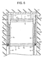
- Fig. 5 is a longitudinal sectional view of an elevator apparatus according to Embodiment 2 of the present invention
- Fig. 6 is a sectional view taken along the arrow line VI-VI of Fig. 5
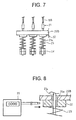
- Fig. 7 is an enlarged view of portion D of Fig. 6
- Fig. 8 is a diagram illustrating a method for measuring the rope tension in the elevator apparatus of Embodiment 2 of the present invention.
- the hoist rope is composed of a first hoist rope 18A for suspending the first counter weight 10A and a second hoist rope 18B for suspending the second counter weight 10B.
- the hoist apparatus 1, the car 5, the first and second counter weights 10A and 10B, the car rails 16, the counter weight rails 17, etc. are arranged in the same way as in Embodiment 1.
- first hoist rope 18A is fixed to the upper portion of the frame member 10b of the first counter weight 10A. And, this first hoist rope 18A is raised from the frame member 10b up to the first drive sheave 4A, and passed along the rope groove of the first drive sheave 4A before being lowered to a level below the car 5. Then, the first hoist rope 18A is fixed to a first car side rope fixation plate 20A mounted to the left lower portion of the car 5.
- one end of the second hoist rope 18B is fixed to the upper portion of the frame member 10b of the second counter weight 10B. And, this second hoist rope 18B is raised from the frame member 10b up to the second drive sheave 4B, and passed along the rope groove of the second drive sheave 4B before being lowered to a level below the car 5. Then, the second hoist rope 18B is fixed to a second car side rope fixation plate 20B mounted to the right lower portion of the car 5.
- each of the terminals of the first and second hoist ropes 18A and 18B is connected to a rope socket 21.
- the rope sockets 21 have rods 21a passed through through-holes 20a of the first and second car side rope fixation plates 20A and 20B, and piezoelectric elements 22 as tension detecting means and compression springs 23 are attached to the extensions of the rods 21a, with tension adjusting nuts 24 being threadedly engaged with the rods 21a to form a tension adjusting mechanism.
- the first and second hoist ropes 18A and 18B are fixed to the first and second car side rope fixation plates 20A and 20B through the intermediation of the tension adjusting mechanisms.
- the tensions of the first and second hoist ropes 18A and 18B are ascertained by measuring, by a tensiometer 25, the pressure applied to the piezoelectric elements 22 held between the first and second car side rope fixation plates 20A and 20B and the compression springs 23.
- the fastening force of the tension adjusting nuts 24 is adjusted beforehand by means of the tensiometer 25 to set the tension of each of the first and second hoist ropes 18A and 18B to a predetermined value.
- the first and second drive motor portions 3A and 3B of the hoist apparatus 1 are drive-controlled by the control device, and the first and second drive sheaves 4A and 4B are rotated with the drive shaft 2.
- first and second hoist ropes 18A and 18B are respectively run by the first and second drive sheaves 4A and 4B, and the car 5 and the first and second counter weights 10A and 10B are guided by the car rails 16 and the counter weight rails 17 to ascend and descend within the hoitsway 15.
- the tensions of the first and second hoist ropes 18A and 18B are measured by the tensiometer 25. And, when the tension of each of the first and second hoist ropes 18A and 18B is deviated from the predetermined value, a similar tension adjusting operation is conducted.
- Embodiment 2 provides the following advantage: since the hoist rope is composed of the first hoist rope 18A for suspending the first counter weight 10A and the hoist rope 18B for suspending the second counter weight 10B, there is no need for the sash pulleys as required in Embodiment 1, thereby simplifying the construction and achieving a reduction in cost.
- Embodiment 2 there is provided a rope tension adjusting mechanism composed of the piezoelectric elements 22, the compression springs 23, and the tension adjusting nuts 24, so that it is possible to adjust as needed the tension of each of the first and second hoist ropes 18A and 18B to a predetermined value.
- a rope tension adjusting mechanism composed of the piezoelectric elements 22, the compression springs 23, and the tension adjusting nuts 24, so that it is possible to adjust as needed the tension of each of the first and second hoist ropes 18A and 18B to a predetermined value.
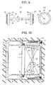
- Fig. 9 illustrates the construction of an elevator hoist apparatus according to Embodiment 3 of the present invention, in which part (a) is a top view and part (b) is a side view.
- Fig. 10 is a plan sectional view of an elevator apparatus according to Embodiment 3 of the present invention
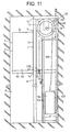
- Fig. 11 is a longitudinal sectional view of the elevator apparatus of Embodiment 3 of the present invention
- Fig. 12 is a sectional view taken along the arrow line XII-XII of Fig. 11
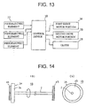
- Fig. 13 is a block diagram showing a control system for the elevator apparatus of Embodiment 3 of the present invention.
- the hoist apparatus 1A of Embodiment 3 is composed of first and second drive shafts 2A and 2B constituting the intermediate portion, a first drive motor portion 3A arranged at one end of the first drive shaft 2A, a first drive sheave 4A secured to one end portion of the first drive shaft 2A outside the first drive motor portion 3A, a second drive motor portion 3B arranged at the other end of the second drive shaft 2B, a second drive sheave 4B secured to the other end portion of the second drive shaft 2B outside the second drive motor portion 3B, and a clutch 26 connecting the other end of the first drive shaft 2A to one end of the second drive shaft 2B.
- the elevator apparatus of Embodiment 3 is of the same construction as that of Embodiment 2 except that the hoist apparatus 1A is used instead of the hoist apparatus 1.
- the fastening force of the tension adjusting nuts 24 is adjusted beforehand by using the tensiometer 25, setting the tension of each of the first and second hoist ropes 18A and 18B to a predetermined value.
- the first and second drive motor portions 3A and 3B of the hoist apparatus 1 are drive-controlled by the control device, and the first and second drive sheaves 4A and 4B are rotated with the drive shaft 2.
- the first and second hoist ropes 18A and 18B are respectively run by the first and second drive sheaves 4A and 4B, and the car 5 and the first and second counter weights 10A and 10B are guided by the car rails 16 and the counter weight rails 17 to ascend and descend within the hoistway 15.
- the control device 30 monitors output signals (rope tension signals) from the piezoelectric elements 22, computing the difference in tension between the first and second hoist ropes 18A and 18B on the basis of the output signals. And, when the difference in tension exceeds a set value, the control device 30 causes the clutch 26 to operate to cancel the connection between the first and second drive shafts 2A and 2B, controlling the rotating angles of the first and the second drive motor portions 3A and 3B such that the difference in tension falls within the range of the set value. And, when the difference in tension has fallen within the range of the set value, the clutch 26 is operated to connect the first and second drive shafts 2A and 2B, and the first and second drive motor portions 3A and 3B are driven at the same rotating angle.
- output signals rope tension signals
- the tension of each of the first and second hoist ropes 18A and 18B is measured. And, when the tension of each of the first and second hoist ropes 18A and 18B is deviated from a predetermined value, a similar tension adjusting operation is conducted.
- Embodiment 3 when there is a difference in tension between the first and second hoist ropes 18A and 18B, the rotating angles of the first and second drive motor portions 3A and 3B are automatically controlled so that the tensions of the ropes may be equalized.
- the rotating angles of the first and second drive motor portions 3A and 3B are automatically controlled so that the tensions of the ropes may be equalized.
- Fig. 14 illustrates an elevator hoist apparatus according to Embodiment 4 of the present invention, in which part (a) is a top view and part (b) is a side view.
- Fig. 15 is a plan sectional view of an elevator apparatus according to Embodiment 4 of the present invention;
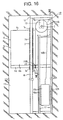
- Fig. 16 is a longitudinal sectional view of the elevator apparatus of Embodiment 4 of the present invention; and
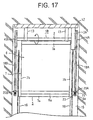
- Fig. 17 is a sectional view taken along the arrow line XVII-XVII of Fig. 16.
- the hoist apparatus 1B of Embodiment 4 is composed of the drive shaft 2 constituting an intermediate portion, the first drive motor portion 3A arranged at one end of the drive shaft 2, the first drive sheave 4A secured to one end portion of the drive shaft 2 outside the first drive motor portion 3A, and the second drive sheave 4B secured to the other end portion of the drive shaft 2.
- the elevator apparatus of this Embodiment 4 is of the same construction as that of Embodiment 2 except that the hoist apparatus 1B is used instead of the hoist apparatus 1.
- the fastening force of the tension adjusting nuts 24 is adjusted beforehand by using the tensiometer 25, setting the tensions of the first and second hoist ropes 18A and 18B to a predetermined value.
- the first drive motor portion 3A of the hoist apparatus 1B is drive-controlled by the control device, and the first and second drive sheaves 4A and 4B are rotated with the drive shaft 2.
- the first and second hoist ropes 18A and 18B are respectively run by the first and second drive sheaves 4A and 4B, and the car 5 and the first and second counter weights 10A and 10B are guided by the car rails 16 and the counter weight rails 17 to ascend and descend within the hoistway 15.
- the tension of each of the first and second hoist ropes 18A and 18B is measured by using the tensiometer 25. And, when the tension of each of the first and second hoist ropes 18A and 18B is deviated from a predetermined value, a similar tension adjusting operation is conducted.
- the hoist apparatus 1B of Embodiment 4 in which the drive sheave is composed of the first and second drive sheaves 4A and 4B arranged at the ends of the drive shaft 2, allows shared running of a requisite number of ropes by the first and second drive sheaves 4A and 4B.
- an increase in the thickness of the first and second drive sheaves 4A and 4B is restrained, so that it is possible to arrange the first drive motor portion 3A and the first and second drive sheaves 4A and 4B in the gaps between the right and left portions of the peripheral wall 6b of the car 5 and the wall surfaces of the hoistway 15.
- the drive motor portion is formed solely by the first drive motor portion 3A, whereby a reduction in cost is achieved.
- first and second drive sheaves which are coaxially opposed to each other, a drive shaft which has a diameter smaller than that of the first and second drive sheaves and connects the first and second drive sheaves to each other, and first and second drive motor portions which are respectively arranged at both ends of the drive shaft, whereby it is possible to obtain an elevator hoist apparatus in which the height of the top portion of the hoistway can be reduced.
- the drive shaft is divided into first and second drive shafts, which are connected together through the intermediation of a clutch, whereby it is possible to eliminate a difference in tension between the hoist ropes.
- first and second drive sheaves which are coaxially opposed to each other, a drive shaft which has a diameter smaller than that of the first and second drive sheaves and connects the first and second drive sheaves to each other, and a drive motor portion which is arranged at one end of the drive shaft so as to be adjacent to the first drive sheave, whereby it is possible to obtain a low-priced elevator hoist apparatus which allows a reduction in the height of the top portion of the hoistway.
- an elevator apparatus including a hoistway; a car arranged as to be capable of ascending and descending while being guided by car rails extending in the direction in which the hoistway extends; first and second counter weights arranged so as to be capable of ascending and descending while being guided by counter weight rails extending in the direction in which the hoistway extends and respectively situated in gaps between the car and the hoistway in the width direction of the car; a hoist rope suspending the car and the first and second counter weights; and a hoist apparatus arranged at the top portion of the hoistway, in which the hoist apparatus has first and second drive sheaves which are coaxially opposed to each other, a drive shaft which has a diameter smaller than that of the first and second drive sheaves and connects the first and second drive sheaves to each other, and first and second drive motor portions which are respectively arranged at both ends of the drive shaft, and in which the hoist apparatus is arranged at the top portion of the hoistway such that the first drive sheave and the first
- the hoist rope is composed of a first hoist rope looped around the first drive sheave and fixed to the car and the first counter weight, and a second hoist rope looped around the second drive sheave and fixed to the car and the second counter weight, whereby the number of sash pulleys is reduced, thereby achieving a reduction in cost.
- the drive shaft is composed of first and second drive shafts connected together through the intermediation of a clutch, and there are provided a tension detecting means that detects the respective tensions of the first and second hoist ropes; and a control device that monitors the tensions of the first and second hoist monitors on the basis of output signals from the tension detecting means and that cancels the connection of the first and second drive shafts through the clutch when there is a difference in tension between the first and second hoist ropes, controlling the rotating angles of the first and second drive motor portions such that the difference in tension falls within a permissible range, whereby it is possible to automatically eliminate the difference in tension between the first and second hoist ropes.
- an elevator apparatus including: a hoistway; a car arranged so as to be capable of ascending and descending while being guided by car rails extending in the direction in which the hoistway extends; first and second counter weights arranged so as to be capable of ascending and descending while being guided by counter weight rails extending in the direction in which the hoistway extends and respectively situated in the gaps between the car and the hoistway in the width direction of the car; a hoist rope suspending the car and the first and second counter weights; and a hoist apparatus arranged at the top portion of the hoistway, in which the hoist apparatus has first and second drive sheaves which are coaxially opposed to each other, a drive shaft which has a diameter smaller than that of the first and second drive sheaves and connects the first and second drive sheaves to each other, and a drive motor portion which is arranged at one end of the drive shaft so as to be adjacent to the first drive sheave, and in which the hoist apparatus is arranged at the top portion of the ho
- the hoist apparatus is arranged such that the drive shaft does not overlap an upper protrusion of the car with respect to the direction in which the hoistway extends, whereby it is possible to further reduce the height of the top portion of the hoistway.
Landscapes
- Engineering & Computer Science (AREA)
- Civil Engineering (AREA)
- Mechanical Engineering (AREA)
- Structural Engineering (AREA)
- Automation & Control Theory (AREA)
- Lift-Guide Devices, And Elevator Ropes And Cables (AREA)
- Cage And Drive Apparatuses For Elevators (AREA)
Abstract
Description
Fig. 12 is a sectional view taken along the arrow line XII-XII of Fig. 11; and Fig. 13 is a block diagram showing a control system for the elevator apparatus of Embodiment 3 of the present invention.
Claims (8)
- An elevator hoist apparatus characterized by comprising: first and second drive sheaves coaxially opposed to each other; a drive shaft having a diameter smaller than that of the first and second sheaves and connecting the first and second drive sheaves to each other; and first and second drive motor portions respectively arranged at both ends of the drive shaft.
- An elevator hoist apparatus according to Claim 1, characterized in that the drive shaft is divided into first and second drive shafts, which are connected together through the intermediation of a clutch.
- An elevator hoist apparatus characterized by comprising: first and second drive sheaves coaxially opposed to each other; a drive shaft having a diameter smaller than that of the first and second sheaves and connecting the first and second drive sheaves to each other; and a drive motor portion arranged at one end of the drive shaft so as to be adjacent to the first drive sheave.
- An elevator apparatus comprising: a hoistway; a car arranged so as to be capable of ascending and descending while being guided by car rails extending in a direction in which the hoistway extends; first and second counter weights arranged so as to be capable of ascending and descending while being guided by counter weight rails extending in the direction in which the hoistway extends so as to be respectively situated in gaps between the car and the hoistway in a width direction of the car; a hoist rope suspending the car and the first and second counter weights; and a hoist apparatus arranged at a top portion of the hoistway, characterized in that:the hoist apparatus comprises first and second drive sheaves which are coaxially opposed to each other, a drive shaft which has a diameter smaller than that of the first and second drive sheaves and connects the first and second drive sheaves to each other, and first and second drive motor portions which are respectively arranged at both ends of the drive shaft; andthe hoist apparatus is arranged at the top portion of the hoistway such that the first drive sheave and the first drive motor portion are arranged close to the wall surface of the hoistway adjacent to the first counter weight and situated so as not to overlap the car with respect to the direction in which the hoistway extends, and that the second drive sheave and the second drive motor portion are arranged close to the wall surface of the hoistway adjacent to the second counter weight and situated so as not to overlap the car with respect to the direction in which the hoistway extends.
- An elevator apparatus according to Claim 4, characterized in that the hoist rope comprises a first hoist rope looped around the first drive sheave and fixed to the car and the first counter weight, and a second hoist rope looped around the second drive sheave and fixed to the car and the second counter weight.
- An elevator apparatus according to Claim 5, wherein the drive shaft is formed by connecting first and second drive shafts to each other through the intermediation of a clutch, and the apparatus further comprising a tension detecting means that detects the respective tensions of the first and second hoist ropes, and a control device that monitors the tensions of the first and second hoist ropes on the basis of output signals from the tension detecting means and cancels the connection of the first and second drive shafts through the clutch when there is a difference in tension between the first and second hoist ropes, controlling rotating angles of the first and second drive motor portions such that the difference in tension falls within a permissible range.
- An elevator apparatus comprising: a hoistway; a car arranged so as to be capable of ascending and descending while being guided by car rails extending in a direction in which the hoistway extends; first and second counter weights arranged so as to be capable of ascending and descending while being guided by counter weight rails extending in the direction in which the hoistway extends so as to be respectively situated in gaps between the car and the hoistway in a width direction of the car; a hoist rope suspending the car and the first and second counter weights; and a hoist apparatus arranged at a top portion of the hoistway, characterized in that:the hoist apparatus comprises first and second drive sheaves which are coaxially opposed to each other, a drive shaft which has a diameter smaller than that of the first and second drive sheaves and connects the first and second drive sheaves to each other, and a drive motor portion which is arranged at one end of the drive shaft so as to be adjacent to the first drive sheave; andthe hoist apparatus is arranged at the top portion of the hoistway such that the first drive sheave and the drive motor portion are arranged close to the wall surface of the hoistway adjacent to the first counter weight and situated so as not to overlap the car with respect to the direction in which the hoistway extends, and that the second drive sheave is arranged close to the wall surface of the hoistway adjacent to the second counter weight and situated so as not to overlap the car with respect to the direction in which the hoistway extends.
- An elevator apparatus according to any one of Claims 4 through 7, characterized in that the hoist apparatus is arranged such that the drive shaft is situated so as not to overlap a protrusion on an upper portion of the car with respect to the direction in which the hoistway extends.
Applications Claiming Priority (1)
| Application Number | Priority Date | Filing Date | Title |
|---|---|---|---|
| PCT/JP2002/002507 WO2003078290A1 (en) | 2002-03-15 | 2002-03-15 | Elevator winch and elevator device |
Publications (2)
| Publication Number | Publication Date |
|---|---|
| EP1486451A1 true EP1486451A1 (en) | 2004-12-15 |
| EP1486451A4 EP1486451A4 (en) | 2010-12-22 |
Family
ID=27854621
Family Applications (1)
| Application Number | Title | Priority Date | Filing Date |
|---|---|---|---|
| EP02705264A Withdrawn EP1486451A4 (en) | 2002-03-15 | 2002-03-15 | Elevator winch and elevator device |
Country Status (5)
| Country | Link |
|---|---|
| EP (1) | EP1486451A4 (en) |
| JP (1) | JPWO2003078290A1 (en) |
| KR (1) | KR100597941B1 (en) |
| CN (1) | CN1261343C (en) |
| WO (1) | WO2003078290A1 (en) |
Cited By (3)
| Publication number | Priority date | Publication date | Assignee | Title |
|---|---|---|---|---|
| EP1538121A4 (en) * | 2002-09-11 | 2011-03-30 | Mitsubishi Electric Corp | ELEVATOR CONTROL ORDER |
| EP1693330A4 (en) * | 2003-12-11 | 2011-07-06 | Mitsubishi Electric Corp | LIFTING DEVICE |
| EP2130792A4 (en) * | 2007-03-23 | 2013-10-23 | Mitsubishi Electric Corp | ELEVATOR CONTROL SYSTEM |
Families Citing this family (2)
| Publication number | Priority date | Publication date | Assignee | Title |
|---|---|---|---|---|
| US9994425B1 (en) | 2016-12-12 | 2018-06-12 | Thyssenkrupp Elevator Ag | Compact motor arrangement with integrated brakes and shaft bearings |
| CN115159301B (en) * | 2022-07-19 | 2023-08-15 | 南京高立工程机械有限公司 | Lifting machine |
Family Cites Families (7)
| Publication number | Priority date | Publication date | Assignee | Title |
|---|---|---|---|---|
| JPS4614781Y1 (en) * | 1966-05-31 | 1971-05-24 | ||
| CA1036080A (en) * | 1976-02-13 | 1978-08-08 | Canadian General Electric Company Limited | Unit hoist |
| JPH0570057A (en) * | 1991-09-17 | 1993-03-23 | Hitachi Building Syst Eng & Service Co Ltd | Elevator device |
| DE9205254U1 (en) * | 1992-04-15 | 1992-06-17 | C. Haushahn Gmbh & Co, 70469 Stuttgart | Drive for rope lifts |
| JP3152034B2 (en) * | 1993-10-28 | 2001-04-03 | 三菱電機株式会社 | Traction sheave type elevator device |
| JP4771586B2 (en) * | 2000-12-08 | 2011-09-14 | 東芝エレベータ株式会社 | elevator |
| JP2002179358A (en) * | 2000-12-19 | 2002-06-26 | Fujitec Co Ltd | Elevator device |
-
2002
- 2002-03-15 JP JP2003576310A patent/JPWO2003078290A1/en active Pending
- 2002-03-15 KR KR1020047000169A patent/KR100597941B1/en not_active Expired - Fee Related
- 2002-03-15 EP EP02705264A patent/EP1486451A4/en not_active Withdrawn
- 2002-03-15 WO PCT/JP2002/002507 patent/WO2003078290A1/en not_active Ceased
- 2002-03-15 CN CNB028141008A patent/CN1261343C/en not_active Expired - Fee Related
Cited By (4)
| Publication number | Priority date | Publication date | Assignee | Title |
|---|---|---|---|---|
| EP1538121A4 (en) * | 2002-09-11 | 2011-03-30 | Mitsubishi Electric Corp | ELEVATOR CONTROL ORDER |
| EP1693330A4 (en) * | 2003-12-11 | 2011-07-06 | Mitsubishi Electric Corp | LIFTING DEVICE |
| EP2551228A1 (en) * | 2003-12-11 | 2013-01-30 | Mitsubishi Denki Kabushiki Kaisha | Elevator apparatus |
| EP2130792A4 (en) * | 2007-03-23 | 2013-10-23 | Mitsubishi Electric Corp | ELEVATOR CONTROL SYSTEM |
Also Published As
| Publication number | Publication date |
|---|---|
| KR20040013117A (en) | 2004-02-11 |
| JPWO2003078290A1 (en) | 2005-07-14 |
| CN1261343C (en) | 2006-06-28 |
| EP1486451A4 (en) | 2010-12-22 |
| KR100597941B1 (en) | 2006-07-06 |
| CN1527792A (en) | 2004-09-08 |
| WO2003078290A1 (en) | 2003-09-25 |
Similar Documents
| Publication | Publication Date | Title |
|---|---|---|
| US6193018B1 (en) | Belt-climbing elevator having drive in counterweight | |
| US7117977B2 (en) | Elevator apparatus including car with suspending pulley devices on opposite sides of the car | |
| CA2439189C (en) | Drive engine for a lift installation and method of mounting a drive engine | |
| KR100374659B1 (en) | Traction type elevator | |
| EP1333000A1 (en) | A machine-roomless traction sheave elevator | |
| JP4110096B2 (en) | Elevator equipment | |
| CN100497147C (en) | Elevator device | |
| EP1602614A1 (en) | Elevator equipment | |
| EP1486451A1 (en) | Elevator winch and elevator device | |
| US7775326B2 (en) | Elevator apparatus | |
| EP1512652B1 (en) | Elevator | |
| EP1535875B1 (en) | Elevator device | |
| US7178636B2 (en) | Elevator system | |
| CN100457592C (en) | Elevator device | |
| EP1741660A1 (en) | Elevator apparatus | |
| WO2006018868A1 (en) | Elevator device | |
| EP1544150A1 (en) | Elevator equipment | |
| EP1571112B1 (en) | Elevator apparatus | |
| EP1808399A2 (en) | Belt-climbing elevator having drive in counterweight | |
| KR200292404Y1 (en) | Fixing apparatus of traction machine-room-ress elevator | |
| KR20060026486A (en) | Elevator Winches and Elevator Devices | |
| EP1736431B1 (en) | Elevator apparatus | |
| JP2000118911A (en) | elevator | |
| HK1093193A1 (en) | Elevator device | |
| HK1093193B (en) | Elevator device |
Legal Events
| Date | Code | Title | Description |
|---|---|---|---|
| PUAI | Public reference made under article 153(3) epc to a published international application that has entered the european phase |
Free format text: ORIGINAL CODE: 0009012 |
|
| 17P | Request for examination filed |
Effective date: 20031212 |
|
| AK | Designated contracting states |
Kind code of ref document: A1 Designated state(s): AT BE CH CY DE DK ES FI FR GB GR IE IT LI LU MC NL PT SE TR |
|
| AX | Request for extension of the european patent |
Extension state: AL LT LV MK RO SI |
|
| RAP1 | Party data changed (applicant data changed or rights of an application transferred) |
Owner name: MITSUBISHI DENKI KABUSHIKI KAISHA |
|
| A4 | Supplementary search report drawn up and despatched |
Effective date: 20101123 |
|
| 17Q | First examination report despatched |
Effective date: 20120522 |
|
| STAA | Information on the status of an ep patent application or granted ep patent |
Free format text: STATUS: THE APPLICATION IS DEEMED TO BE WITHDRAWN |
|
| 18D | Application deemed to be withdrawn |
Effective date: 20141001 |