EP1486343A2 - Droplet placement sampling - Google Patents
Droplet placement sampling Download PDFInfo
- Publication number
- EP1486343A2 EP1486343A2 EP04253045A EP04253045A EP1486343A2 EP 1486343 A2 EP1486343 A2 EP 1486343A2 EP 04253045 A EP04253045 A EP 04253045A EP 04253045 A EP04253045 A EP 04253045A EP 1486343 A2 EP1486343 A2 EP 1486343A2
- Authority
- EP
- European Patent Office
- Prior art keywords
- test media
- printhead
- test
- holder
- media
- Prior art date
- Legal status (The legal status is an assumption and is not a legal conclusion. Google has not performed a legal analysis and makes no representation as to the accuracy of the status listed.)
- Withdrawn
Links
Images


Classifications
-
- B—PERFORMING OPERATIONS; TRANSPORTING
- B41—PRINTING; LINING MACHINES; TYPEWRITERS; STAMPS
- B41J—TYPEWRITERS; SELECTIVE PRINTING MECHANISMS, i.e. MECHANISMS PRINTING OTHERWISE THAN FROM A FORME; CORRECTION OF TYPOGRAPHICAL ERRORS
- B41J29/00—Details of, or accessories for, typewriters or selective printing mechanisms not otherwise provided for
- B41J29/38—Drives, motors, controls or automatic cut-off devices for the entire printing mechanism
- B41J29/393—Devices for controlling or analysing the entire machine ; Controlling or analysing mechanical parameters involving printing of test patterns
-
- B—PERFORMING OPERATIONS; TRANSPORTING
- B41—PRINTING; LINING MACHINES; TYPEWRITERS; STAMPS
- B41J—TYPEWRITERS; SELECTIVE PRINTING MECHANISMS, i.e. MECHANISMS PRINTING OTHERWISE THAN FROM A FORME; CORRECTION OF TYPOGRAPHICAL ERRORS
- B41J2/00—Typewriters or selective printing mechanisms characterised by the printing or marking process for which they are designed
- B41J2/005—Typewriters or selective printing mechanisms characterised by the printing or marking process for which they are designed characterised by bringing liquid or particles selectively into contact with a printing material
- B41J2/01—Ink jet
- B41J2/21—Ink jet for multi-colour printing
- B41J2/2132—Print quality control characterised by dot disposition, e.g. for reducing white stripes or banding
- B41J2/2135—Alignment of dots
-
- B—PERFORMING OPERATIONS; TRANSPORTING
- B41—PRINTING; LINING MACHINES; TYPEWRITERS; STAMPS
- B41J—TYPEWRITERS; SELECTIVE PRINTING MECHANISMS, i.e. MECHANISMS PRINTING OTHERWISE THAN FROM A FORME; CORRECTION OF TYPOGRAPHICAL ERRORS
- B41J25/00—Actions or mechanisms not otherwise provided for
- B41J25/304—Bodily-movable mechanisms for print heads or carriages movable towards or from paper surface
- B41J25/308—Bodily-movable mechanisms for print heads or carriages movable towards or from paper surface with print gap adjustment mechanisms
-
- B—PERFORMING OPERATIONS; TRANSPORTING
- B41—PRINTING; LINING MACHINES; TYPEWRITERS; STAMPS
- B41J—TYPEWRITERS; SELECTIVE PRINTING MECHANISMS, i.e. MECHANISMS PRINTING OTHERWISE THAN FROM A FORME; CORRECTION OF TYPOGRAPHICAL ERRORS
- B41J29/00—Details of, or accessories for, typewriters or selective printing mechanisms not otherwise provided for
- B41J29/02—Framework
-
- B—PERFORMING OPERATIONS; TRANSPORTING
- B41—PRINTING; LINING MACHINES; TYPEWRITERS; STAMPS
- B41J—TYPEWRITERS; SELECTIVE PRINTING MECHANISMS, i.e. MECHANISMS PRINTING OTHERWISE THAN FROM A FORME; CORRECTION OF TYPOGRAPHICAL ERRORS
- B41J2/00—Typewriters or selective printing mechanisms characterised by the printing or marking process for which they are designed
- B41J2/005—Typewriters or selective printing mechanisms characterised by the printing or marking process for which they are designed characterised by bringing liquid or particles selectively into contact with a printing material
- B41J2/01—Ink jet
- B41J2/135—Nozzles
- B41J2/165—Prevention or detection of nozzle clogging, e.g. cleaning, capping or moistening for nozzles
- B41J2/16579—Detection means therefor, e.g. for nozzle clogging
Definitions
- Printing mechanisms such as those used in inkjet printers, may use one or more print cartridges, sometimes referred to as "pens” which may shoot drops of liquid colorant, referred to generally herein as "ink,” onto print media, for instance paper or cardboard.
- Each print cartridge may have a printhead with very small nozzles through which the ink drops are fired using various technologies, such as thermal or piezo-electric inkjet technology. Between incremental advancing steps of the media through a printzone, the printhead may be propelled back and forth across the media while selectively firing drops of ink on the media to form a desired image.
- Some printing mechanisms such as those in industrial settings, for example, may have a fixed or stationary media-wide array printhead, or a stationary group of off-set or "stitched" printheads, that print as the media is continuously moved through the printzone.
- printing mechanisms having one or more printheads it may be desirable to align the printhead(s) with respect to the position of the media during printing.
- printing mechanisms having multiple printheads it may be desirable to align the printheads with respect to one another. For these and other reasons there is a need for the present invention.
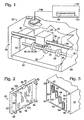
- FIG. 1 illustrates one embodiment of a printing mechanism, here shown as a printer 20, which may include a base chassis 22, and an exterior housing 24.
- a media handling system 25 may include at least one drive roller shaft 26 which may include a series of media drive rollers, such as roller 28, which may propel media through a printzone 30 in incremental advances during printing.
- the shaft 26 and rollers 28 may be considered as a schematic representation of a drive portion of a conveyor assembly, such as a conveyor belt assembly (not shown), for continuously advancing media during printing.
- Drive roller shaft 26 may be rotatably supported by printer chassis 22, for example as shown at support 32.
- Chassis 22 may fixedly support a printhead assembly 33 that may include a carriage support, shown as a guide rod 34.
- Printhead assembly 33 may further include a printhead carriage 35, here illustrated in a position above printzone 30, wherein printhead carriage 35 may be movably supported on guide rod 34.
- printhead carriage 35 may traverse through printzone 30 and into a servicing zone 36 along a scanning axis 38 defined by guide rod 34.
- printhead assembly 33 may not be mobile, and instead may include a printhead mounted on chassis 22 which resides permanently over the printzone 30.
- the illustrated printer 20 of the present embodiment may be used for printing business reports, correspondence, advertising materials, product packaging, desktop publishing, and the like, in an office, home or other environment.
- a variety of printers are commercially available.
- some of the printing mechanisms that may include embodiments of the present invention include industrial printers, package printers, plotters, portable printing units, copiers, cameras, video printers, and facsimile machines, to name a few.
- carriage 35 supports four inkjet printheads 40, 42, 44 and 46 (see FIG. 3), although in other implementations other numbers of printheads may be used. Indeed, carriage 35 when used in a stationary or fixed printing system may be much wider than illustrated in FIG. 1, spanning the entire width of printzone 30, as measured along axis 38, known in the industry as a "page wide array" printer.
- FIG. 2 shows an embodiment of an alignment test assembly 50, also shown in FIG. 1 in a test or sampling position under the printheads 40-46.
- Test assembly 50 may include a card holder body 52 which may be of a plastic, metal, paper or another somewhat rigid material. Card holder body 52 may include card alignment features, illustrated here as a slightly recessed window 54.
- the window 54 may be a rectangular recessed region of the card holder body 52.
- the window 54 may be sized to tightly maintain test media at least partially therein.
- Test assembly 50 may include a piece of test media (or may be the test media target surface itself, for example, if the target media is a disposable paper or cardboard assembly) such as test card 55, which may be located within window 54 for testing.
- the test media may be supported by the printer's media support, such as a platen of the printer.
- test card 55 may be stiff or flexible, depending on the particular application in which the test card is used. For example, if printer 20 is used as a package printer for printing cardboard, it may be desirable to use a piece of cardboard as the test card 55, or if printer 20 is used for printing on fabric, it may be desirable to use a piece of fabric as the test card 55.
- the illustrated embodiment of test card 55 is a high-quality premium or photographic paper.
- test card 55 may be alternatively or additionally secured in place within window 54 by securing members, here illustrated as a pair of clips 56 and 58.
- securing members here illustrated as a pair of clips 56 and 58.
- other types of securing members may be used, for instance clamps (not shown), pins (not shown), adhesive tape (not shown), etc.
- other card alignment features may be used, such as visible indicia markings (not shown) on body 52, or raised features, for instance ribs or ridges (not shown) protruding from the body.
- Clips 56 and 58 may also serve as card alignment features.
- FIG. 3 shows four printheads 40-46 arranged in what is known in the art as a "stitched" or off-set printhead alignment.
- Printheads 40, 42, 44 and 46 may each have a pair of substantially linear nozzle arrays 60, 62, 64 and 66, respectively, although other printheads in other implementations may have different nozzle arrangements.
- FIG. 2 shows test card 55 as having four test patterns 70, 72, 74 and 76 made by sampling, i.e., ejecting ink from, the illustrated nozzle arrays 60, 62, 64 and 66, respectively.
- pen-to-paper spacing either test assembly 50, or carriage 35 (see FIG. 1), or both, may be equipped with a spacing feature, such as a pen-to-paper spacing mechanism, in the illustrated embodiment shown as four standoff posts 80, 82, 84 and 86 projecting from body 52.
- a sampler alignment or datum mechanism may be used to align test assembly 50 with printheads 40-46 (see FIG. 3).
- the alignment mechanism may include four alignment holes 90, 92, 94 and 96 which may be positioned on carriage 35.
- the holes may be located to receive and correspond to standoff posts 80, 82, 84 and 86, respectively.
- Holes 90, 92, 94 and 96 may have a depth such that only a predetermined or selected length of posts 80, 82, 84 and 86, respectively, are received within holes 90, 92, 94 and 96. In this manner, holes 90, 92, 94 and 96 may determine the pen-to-paper spacing 71 (see FIG. 1), i.e., the media to printhead spacing, of the test assembly.
- all or a part of the alignment mechanism may be positioned on printhead assembly 33 that supports printheads 40, 42, 44 and 46 in a stationary position.
- printhead assembly 33 may comprise a support wall (not shown) fastened to chassis 22 (see FIG. 1) wherein the printheads are secured to the support wall (not shown) and the alignment mechanism, such as holes 90, 92, 94 and 96, may be positioned on the support wall adjacent the printheads.
- standoff posts 80-86 and corresponding alignment holes 90-96 addresses both the issues of proper pen-to-paper spacing and alignment of test assembly 50 with printheads 40-46 (see FIG. 3).
- Other mechanical fixtures and devices may be employed to address the PPS and alignment issues.
- using a pair of mating rail features such as rails 81 on test assembly 50 and rails 83 on carriage 35, may allow the test assembly to be slid into a test position under printheads 40-46.
- the standoff post and corresponding alignment hole arrangement illustrated in FIGS. 2 and 3 is shown merely by way of example, and is in no way intended to be limiting on the scope of the claims appended below.
- the holes may be positioned on test assembly 50 and the posts may be positioned on printhead carriage 35.
- posts extending outwardly from printhead 35 may disrupt print media as it passes by the printheads during normal printing operations.
- An alternative to the card alignment device comprising recessed window 54 may comprise an arrangement and size of card 55 or of standoff posts 80-86, such that the posts retain card 55 in an aligned position on test assembly 50.
- the edges of card 55 may define cutouts which surround a portion of the standoff posts, or the card may define holes therethrough sized to completely surround the standoff posts.
- the card edges may have cutouts sized to engage clips 56 and 58 and which may serve as card alignment features.
- FIG. 4 shows one embodiment of a nozzle testing and alignment method 100 for adjusting droplet placement on print media.
- a refreshing operation 102 fresh test card 55 may be placed within window 54 of body 52, and may be secured in place using clips 56 and 58.
- the test card 55 is not mounted on the body 52.
- test assembly 50 may be placed in a test position adjacent to printheads 40-46 by inserting standoff posts 80-86 (see FIG. 2) into their respective associated alignment holes 90-96 (see FIG. 3).
- Posts 80-86 may be sized such that they are frictionally retained within holes 90-96 during testing of the printheads such that test assembly 50 is secured to printhead carriage 35 in a hands-free manner. While the illustrated embodiment of FIG. 1 shows test assembly 50 attached in a hands-free manner to carriage 35, in other implementations, an operator may hold test assembly 50 in the test position.
- a test sample may be gathered by having the nozzles of each array 60-66 (see FIG. 3) eject a single droplet onto test card 55, forming respective test patterns 70-76 (see FIG. 2).
- an optional action of spitting or purging each of the nozzles of printheads 40-46 may be performed.
- several primer spits may serve to remove any minor blockages or occlusions, such as partially dried ink, from a nozzle which has been inactive.
- an entire printhead servicing routine may be performed before engaging operation 104 to assure the printheads are clean and ready to fire an acceptable or satisfactory sample.
- test assembly 50 may be removed from carriage 35, and sample card 55 may be removed from body 52 and placed into a reader device 110 (see FIG. 1).
- Reader device 110 is illustrated as having an input slot 112, although in other embodiments a conventional flatbed scanner may be used to conduct reading operation 114.
- Reader device 110 which may comprise any of a variety of scanning devices, may scan test sample images 70-76 (see FIG. 2) and gather information such as where the droplets actually landed in the test patterns.
- the resolution of reader device 110 may be selected to be greater than or equal to the printhead resolution (e.g. 600 or 1200 dots per inch, or "DPI") to generate test data.
- the printhead resolution e.g. 600 or 1200 dots per inch, or "DPI
- the test sample results may be conveyed via a communication channel 118 to a printer controller 120.
- the conveying operation 116 is illustrated schematically in FIG. 1, and may comprise an electric, optic, radio wave or other signal sent from reader device 110 to controller 120.
- the conveying operation may comprise reader device 110 storing the test result information on a magnetic, optic or other memory medium, which an operator may carry from reader device 110 to an input device on printer 20 or to an input device on a separate computer (not shown) that may control printer 20.
- the term "printer controller" as used herein may include operations conducted by the onboard electronics of printer 20, by driver software resident within a separate computer (not shown) that controls printer 20, or by a combination thereof.
- controller 120 analyzes test data and may adjust printer mechanism settings, such as the nozzle firing sequencing to compensate for any printhead and/or nozzle misalignment discovered using any of a variety of conventional or other nozzle compensation imaging programs.
- printer mechanism settings such as the nozzle firing sequencing to compensate for any printhead and/or nozzle misalignment discovered using any of a variety of conventional or other nozzle compensation imaging programs.
- imaging software may calculate the distance in pixels from one printhead's nozzle pattern to another in both horizontal and vertical directions. Such software may then recommend an image shift in pixels for each of the other printheads, or the software may communicate directly with printer controller 120 so adjustments may be made automatically by the printer electronics.
- Method 100 may also be used to diagnose printhead health.
- imaging software may be constructed that may be capable of detecting missing and misaligned droplets within test patterns 70-76 (see FIG. 2).
- a missing droplet may be compensated for by adjusting a printer mechanism setting such as firing another nozzle(s) as a substitute.
- misdirected or misaligned droplets may be compensated for by adjusting the firing time of the nozzle, or assigning some other nozzle(s) to fire instead.
- using a high-quality print media for test card 55 such as coated premium or photographic media, may mitigate drop-bleed into the media fibers, and may provide high-resolution test patterns 70-76 (see FIG. 2) to conduct such printhead health diagnosis routines.
- method 100 may be considered as an inkjet droplet placement sampling and correction method, which may be used to detect and correct printhead to print media misalignment, printhead to printhead misalignment, and to detect printhead health issues, such as missing or misaligned nozzles.
- test card 55 may include preprinted reference indicia, such as horizontal and vertical markings 124 (see FIG. 2).
- Reference indicia 124 may also be scanned during reading operation 114, and conveyed in operation 116 to controller 120.
- controller 120 may use the position of the reference indicia 124 to determine whether any of the test patterns 70-76 (see FIG. 2) are rotated with respect to the reference markings, and then compensate for such rotation, if any, by adjusting the nozzle firing sequence.
- Patterns of reference indicia may be used, such as a company or brand logo, printed information about the types of printers the test card accommodates, blank lines for an operator to record information about the test sample, phrases, a logo or design, etc.
- Preprinted or blank test media may be packaged and sold as a consumable product sized to fit the particular body 52 recommended for a particular printhead configuration.
- FIGS. 1-6 are shown to illustrate the principles and concepts of the invention as set forth in the claims below, and a variety of modifications and variations may be employed in various implementations while still falling within the scope of the claims below.
Landscapes
- Engineering & Computer Science (AREA)
- Quality & Reliability (AREA)
- Ink Jet (AREA)
Abstract
Description
Claims (10)
- A system (20) for sampling droplet placement in a printing mechanism having a printhead assembly (33) that supports a printhead (40), comprising:a test media holder (50) removably coupled to the printhead assembly (33 during sampling; anda test media (55) supported by said holder (50) to receive sample droplets from the printhead (40).
- A system (20) according to claim 1, further comprising a test media reader device (110) which examines the test media (55) and generates sample droplet placement information, and a controller (120) configured to generate correction information used to change printing mechanism settings based on the sample droplet placement information.
- A system (20) according to claim 2, further comprising a communication link between the reader device (110) and the controller (120) to communicate said information to the controller (120).
- A system (20) according to claim 1 further comprising an alignment structure (80) on said test media holder (50) that establishes a selected printhead to test media spacing (71) during sampling.
- A system (20) according to claim 1 further comprising an alignment structure (80) on said test media holder that engages corresponding alignment structure (90) on said printhead assembly (33).
- A system (20) according to claim 5 wherein said alignment structure (80) comprises projections and said corresponding alignment structure (90) comprises holes.
- A system (20) according to claim 1 wherein the test media holder (50) further includes media alignment structure (54) to align the test media.
- A test media holder (50) comprising:a body (52) having a first surface for maintaining test media (55) in a position thereon to receive test droplets ejected from a printhead (40) during testing; andalignment features (80) formed at the first surface for removably engaging the body (52) during testing with a printhead assembly (33) that supports said printhead (40).
- A method of correcting inkjet droplet placement in a printing mechanism (20) having a printhead assembly (33), comprising:securing test media on a test media holder (50);engaging said holder (50) with the printhead assembly (33);collecting sample droplets on the test media (55);disengaging said holder (50) from the printhead assembly (33);analyzing the sample droplets; andadjusting printing mechanism settings in response to said analyzing.
- A method according to claim 9 further comprising:removing the test media (55) from said holder (50); andwherein said analyzing comprises reading the test media with a reader device (110).
Applications Claiming Priority (2)
| Application Number | Priority Date | Filing Date | Title |
|---|---|---|---|
| US10/457,165 US20040246289A1 (en) | 2003-06-09 | 2003-06-09 | Droplet placement sampling |
| US457165 | 2003-06-09 |
Publications (2)
| Publication Number | Publication Date |
|---|---|
| EP1486343A2 true EP1486343A2 (en) | 2004-12-15 |
| EP1486343A3 EP1486343A3 (en) | 2004-12-29 |
Family
ID=33299614
Family Applications (1)
| Application Number | Title | Priority Date | Filing Date |
|---|---|---|---|
| EP04253045A Withdrawn EP1486343A3 (en) | 2003-06-09 | 2004-05-24 | Droplet placement sampling |
Country Status (3)
| Country | Link |
|---|---|
| US (1) | US20040246289A1 (en) |
| EP (1) | EP1486343A3 (en) |
| JP (1) | JP2005001386A (en) |
Cited By (1)
| Publication number | Priority date | Publication date | Assignee | Title |
|---|---|---|---|---|
| EP1878582A1 (en) * | 2006-07-11 | 2008-01-16 | FUJIFILM Corporation | Inkjet recording apparatus |
Families Citing this family (3)
| Publication number | Priority date | Publication date | Assignee | Title |
|---|---|---|---|---|
| US9390352B2 (en) | 2008-04-22 | 2016-07-12 | Hewlett-Packard Development Company, L.P. | Concurrent image and diagnostic pattern printing |
| JP6154384B2 (en) * | 2011-09-23 | 2017-06-28 | ウオーターズ・テクノロジーズ・コーポレイシヨン | Solid phase extraction device for dry sample cards |
| US10477034B2 (en) * | 2018-04-09 | 2019-11-12 | Xerox Corporation | Digital image-paper registration error correction through image shear |
Family Cites Families (6)
| Publication number | Priority date | Publication date | Assignee | Title |
|---|---|---|---|---|
| ATE225540T1 (en) * | 1993-05-27 | 2002-10-15 | Canon Kk | METHOD AND APPARATUS FOR INKJET RECORDING |
| US5627571A (en) * | 1994-10-13 | 1997-05-06 | Xerox Corporation | Drop sensing and recovery system for an ink jet printer |
| JPH11188896A (en) * | 1997-12-26 | 1999-07-13 | Canon Inc | Image recording apparatus and method |
| US6345876B1 (en) * | 1999-03-05 | 2002-02-12 | Hewlett-Packard Company | Peak-valley finder process for scanned optical relative displacement measurements |
| US6378975B1 (en) * | 1999-04-30 | 2002-04-30 | Hewlett-Packard Company | Drop detection using a movable strip |
| US6554398B2 (en) * | 2001-03-08 | 2003-04-29 | Agfa-Gevaert | Ink-jet printer equipped for aligning the printheads |
-
2003
- 2003-06-09 US US10/457,165 patent/US20040246289A1/en not_active Abandoned
-
2004
- 2004-05-24 EP EP04253045A patent/EP1486343A3/en not_active Withdrawn
- 2004-06-08 JP JP2004169829A patent/JP2005001386A/en not_active Withdrawn
Cited By (4)
| Publication number | Priority date | Publication date | Assignee | Title |
|---|---|---|---|---|
| EP1878582A1 (en) * | 2006-07-11 | 2008-01-16 | FUJIFILM Corporation | Inkjet recording apparatus |
| US7681978B2 (en) | 2006-07-11 | 2010-03-23 | Fujifilm Corporation | Inkjet recording apparatus |
| EP2172344A1 (en) * | 2006-07-11 | 2010-04-07 | FUJIFILM Corporation | Inkjet recording apparatus |
| US8201914B2 (en) | 2006-07-11 | 2012-06-19 | Fujifilm Corporation | Inkjet recording apparatus |
Also Published As
| Publication number | Publication date |
|---|---|
| JP2005001386A (en) | 2005-01-06 |
| US20040246289A1 (en) | 2004-12-09 |
| EP1486343A3 (en) | 2004-12-29 |
Similar Documents
| Publication | Publication Date | Title |
|---|---|---|
| US6769756B2 (en) | Ink drop detector configurations | |
| US7533962B2 (en) | Ink jet printing apparatus and ink jet printing method | |
| JP5353755B2 (en) | Image forming apparatus | |
| JPH0596796A (en) | Recording method and device | |
| JP2020104387A (en) | Ink jet printer | |
| EP1486343A2 (en) | Droplet placement sampling | |
| JP3815055B2 (en) | Print medium conveying apparatus and printer | |
| JP3882708B2 (en) | Recording apparatus, program, and computer system | |
| US6474765B2 (en) | Inkjet printing and method | |
| US6409305B1 (en) | Full bleed printmode to minimize overspray | |
| JP2001129983A (en) | Ink jet recording apparatus and adjustment method thereof | |
| JP2010131793A (en) | Maintenance unit and inkjet printer | |
| JP5229019B2 (en) | Image forming apparatus | |
| JP2005047026A (en) | Printing apparatus, computer program, printing system, printing method, and medium unit | |
| JP4941441B2 (en) | Ink jet recording apparatus and borderless recording method | |
| JP4284923B2 (en) | Printing apparatus, computer program, computer system, and printing method | |
| JP4222605B2 (en) | Image forming apparatus | |
| US6578946B1 (en) | Movable ink drop detector pick up for a drop-on-demand printer | |
| EP1518695B1 (en) | Method and system for printhead rotation detection using photosensors | |
| JP4957004B2 (en) | Inkjet recording device | |
| WO2004071774A1 (en) | Liquid jetting device, liquid jetting method, and liquid jetting system | |
| JPH10235885A (en) | Ink jet printer | |
| JP2008018604A (en) | Inkjet recording device | |
| JPH11105309A (en) | Recording head and ink recording apparatus using the same | |
| JP2005007775A (en) | Liquid discharge apparatus, liquid discharge method, and liquid discharge system |
Legal Events
| Date | Code | Title | Description |
|---|---|---|---|
| PUAI | Public reference made under article 153(3) epc to a published international application that has entered the european phase |
Free format text: ORIGINAL CODE: 0009012 |
|
| PUAL | Search report despatched |
Free format text: ORIGINAL CODE: 0009013 |
|
| AK | Designated contracting states |
Kind code of ref document: A2 Designated state(s): AT BE BG CH CY CZ DE DK EE ES FI FR GB GR HU IE IT LI LU MC NL PL PT RO SE SI SK TR |
|
| AX | Request for extension of the european patent |
Extension state: AL HR LT LV MK |
|
| AK | Designated contracting states |
Kind code of ref document: A3 Designated state(s): AT BE BG CH CY CZ DE DK EE ES FI FR GB GR HU IE IT LI LU MC NL PL PT RO SE SI SK TR |
|
| AX | Request for extension of the european patent |
Extension state: AL HR LT LV MK |
|
| 17P | Request for examination filed |
Effective date: 20050404 |
|
| AKX | Designation fees paid |
Designated state(s): DE GB IT NL |
|
| STAA | Information on the status of an ep patent application or granted ep patent |
Free format text: STATUS: THE APPLICATION IS DEEMED TO BE WITHDRAWN |
|
| 18D | Application deemed to be withdrawn |
Effective date: 20060425 |