EP1486296B1 - Screwdriver bit package - Google Patents
Screwdriver bit package Download PDFInfo
- Publication number
- EP1486296B1 EP1486296B1 EP04012740A EP04012740A EP1486296B1 EP 1486296 B1 EP1486296 B1 EP 1486296B1 EP 04012740 A EP04012740 A EP 04012740A EP 04012740 A EP04012740 A EP 04012740A EP 1486296 B1 EP1486296 B1 EP 1486296B1
- Authority
- EP
- European Patent Office
- Prior art keywords
- tool
- tool bit
- retainer
- container
- housings
- Prior art date
- Legal status (The legal status is an assumption and is not a legal conclusion. Google has not performed a legal analysis and makes no representation as to the accuracy of the status listed.)
- Expired - Lifetime
Links
- 239000006260 foam Substances 0.000 claims description 2
- 238000013016 damping Methods 0.000 claims 2
- 230000008878 coupling Effects 0.000 claims 1
- 238000010168 coupling process Methods 0.000 claims 1
- 238000005859 coupling reaction Methods 0.000 claims 1
- 229920001169 thermoplastic Polymers 0.000 claims 1
- 239000004416 thermosoftening plastic Substances 0.000 claims 1
- 239000000463 material Substances 0.000 description 3
- 230000037431 insertion Effects 0.000 description 1
- 238000003780 insertion Methods 0.000 description 1
- 230000014759 maintenance of location Effects 0.000 description 1
- 230000000717 retained effect Effects 0.000 description 1
Images


Classifications
-
- B—PERFORMING OPERATIONS; TRANSPORTING
- B25—HAND TOOLS; PORTABLE POWER-DRIVEN TOOLS; MANIPULATORS
- B25H—WORKSHOP EQUIPMENT, e.g. FOR MARKING-OUT WORK; STORAGE MEANS FOR WORKSHOPS
- B25H3/00—Storage means or arrangements for workshops facilitating access to, or handling of, work tools or instruments
- B25H3/003—Holders for drill bits or the like
Definitions
- the present invention relates to tool containers and, more particularly, to a container for tools such as screwdriver bits, drill bits, or the like.
- German Utility Model No. G 92 05 913 discloses a tool container according to the pre-characterising portion of claim 1.
- Several of the containers have various types of retention mechanism to retain the tool bits in the container. Some of the containers are opened to enable the user direct access to the tool bits. However, some of the containers enclose the bit holder so that they must be opened in order to enable access to the tool bits. In these cases, sometimes the bit holders are stationary with the bits secured in the bit holder.
- some of these containers include a device for carrying an extension bit or the like.
- the extension bit of the like may be secured directly to the container or may be placed into a retainer. While these tool containers appear to work satisfactorily for their intended purposes designers strive to improve the art.
- the present invention provides a compact tool container to carry a plurality of tool bits.
- the container includes a clam shell housing which moves from a closed to an open position to enable access to the bits.
- the tool holder is rotatable independently of the housing so that, in an open position, the tool holder can be rotated.
- the tool bit container includes a compartment which may be accessed when the container is in the open or closed position.
- a tool container comprises a first and second housing.
- a tool retainer is movably coupled with the first and second housings. The first and second housing move from a closed position, surrounding the tool retainer prohibiting access to the tool retainer, to an open position, enabling access to the tool retainer.
- the tool retainer is independently rotatable with respect to the first and second housing in the open position.
- the tool retainer has at least one member to retain a tool bit on the tool retainer.
- the tool retainer has a compartment which is accessible when the first and second housing are in both the open and closed position.
- a movable door covers the compartment.
- the tool retainer includes a pivot.
- the first and second housings include openings which couple with the pivot to enable rotation.
- the compartment is formed by a bore through the pivot.
- the tool retainer includes a slot to receive a tool bit holder.
- the tool bit holder includes the at least one member to retain a tool and is manufactured from a thermal plastic material.
- Each member for retaining a tool includes a circumferential wall defining a bore with at least one projection extending radially inward to contact a tool bit to be retained in the bore.
- there are four projections which extend axially along the circumferential wall.
- the first and second housings open with respect to one another so that an angle is formed between the two of up to 190°.
- the first and second housings may be transparent enabling viewing of the tool bits inside the container.
- the tool retainer is pivotable along an arc from about 0 to about 45 ° with respect to the housings.
- a latch is included to lock the first and second housings in the closed position.
- a tool container is shown and designated with the reference numeral 10.
- the tool container includes a first housing 12 and a second housing 14.
- the housings 12 and 14 may be transparent enabling viewing inside of the tool container.
- the containers are shown in a closed position wherein a latch 16 locks the housings 12 and 14 together.
- a tool bit retainer 18 is positioned inside of the housings 12 and 14.
- the housing 12 includes a base 22 which includes a continuous curved wall 24. Curved wall 24 includes offset portions 25 and 27 which enhance opening of the housings 12 and 14. Sidewalls 26 and 28 extend from the base and are continuous with the curved wall 24. The sidewalls 26 and 28 at their free ends include apertures 30 and 32 which secure to the tool holder 18.
- the sidewall 28 includes a flange 34 surrounding a slot 36. A door 38 with a projection 40, which fits into slot 36, slides within the flange 34. The door 38 is slidable inside the flange to cover a compartment which will be explained later.
- the housing 14 includes a base 44 with a curved wall 46 and sidewalls 48 and 50.
- Curved wall 46 includes offset portions 47 and 49 which enhance opening of the housings 12 and 14.
- the sidewalls 48 and 50 include apertures 52 and 54 which enable rotation of the housing 14.
- the curved wall 46 like curved wall 24, includes a rail portion 51 for receiving the latch 16 to lock the housing members together.
- the tool bit retainer 18 includes a housing portion 60 and a tool bit holder 62.
- the housing 60 includes a slot 64 to receive the bit holding portion 62.
- the housing portion 60 includes an unitarily formed tube portion 66.
- the tube portion 66 includes a bore 68 which may receive a tool holder or the like.
- Flanges 70 and 72 form a pivot so that the openings on the housings 12 and 14 may fit around the flanges 70 and 72 to enable rotation of the housings as well as the tool retainer 18 with respect to one another.
- the bore 68 is covered by the door 38.
- the door 38 may be opened and closed to expose the bore 68 when the housings are in a closed as well as an opened position. Thus, the bore 68 may be accessed at any time.
- the bore may include a dampening member, such as a foam plug, to prevent rattling noise from a tool bit.
- the tool bit holder 62 has an overall rectangular configuration.
- the tool bit holder 62 is formed from a thermal plastic material. Thus, the tool holder 62 is elastic and may be compressed.
- the tool holder 62 includes a plurality of bore members 80 to receive tool bits.
- the tool bit holder 62 fits into slot 64 of the bit retainer 18 to retain the tool bit holder 62 in the tool bit retainer 18.
- Each of the plurality of bores 80 includes at least one, preferably four, projecting members 82.
- the projecting members 82 extend radially inward from the circumference of the bore 80. Also, the members 82 extend axially along the bore.
- the members 82 are unitarily formed with the tool bit holder 62.
- the projecting members 82 compress to enable further insertion of the tool bit into the bore 80. Due to the elastomeric resilience of the material that makes up the projecting members 82, the projecting members 82 exert a counter force onto the tool bit to retain the tool within the bit holder 62.
- the bores 80 may be identical to retain identical bits. Also, the bores may have varying sizes to retain different sizes of tool bits such as drill bits. Further, indicia may be positioned onto the tool holder or bit retainer 18 to identify to the user which tool bit is in the specific bore 80.
- the apertures 30 and 32, as well as 52 and 54 of the housing members 12 and 14, respectively, are positioned onto the flanges 70 and 72 which form the pivot of the bit retainer 18. Due to this type of connection, the housings 12 and 14 move independently of one another as well as with respect to one another. Likewise, the bit retainer 18 may be moved independently of the housing members 12 and 14. Thus, the bit retainer 18 may be moved from a first position, where it is inside of housing 12, to a second position angled with respect to housing 12. Ordinarily, the bit retainer 18 can be moved to approximately a 45° angle with respect to the housing 12. This allows ready access to the tool bits within the bit retainer.
- the housing members 12 and 14 open with respect to one another along an angle up to 190° as shown in Fig. 4 .
- Stops can be formed along the hoops defining the apertures 30, 32, 52, 54 to contact one another to determine the angle of opening between the two housing members.
- a stop could be mounted on the flanges 70 and 72 to stop movement of the tool retainer 18 with respect to the housings 12 and 14.
Landscapes
- Engineering & Computer Science (AREA)
- Mechanical Engineering (AREA)
- Purses, Travelling Bags, Baskets, Or Suitcases (AREA)
- Packaging Of Annular Or Rod-Shaped Articles, Wearing Apparel, Cassettes, Or The Like (AREA)
- Surgical Instruments (AREA)
- Connector Housings Or Holding Contact Members (AREA)
- Fastening Of Light Sources Or Lamp Holders (AREA)
Abstract
Description
- The present invention relates to tool containers and, more particularly, to a container for tools such as screwdriver bits, drill bits, or the like.
- Various types of containers exist which carry screwdriver bits. German Utility Model No.
G 92 05 913 discloses a tool container according to the pre-characterising portion of claim 1. Several of the containers have various types of retention mechanism to retain the tool bits in the container. Some of the containers are opened to enable the user direct access to the tool bits. However, some of the containers enclose the bit holder so that they must be opened in order to enable access to the tool bits. In these cases, sometimes the bit holders are stationary with the bits secured in the bit holder. - Also, some of these containers include a device for carrying an extension bit or the like. The extension bit of the like may be secured directly to the container or may be placed into a retainer. While these tool containers appear to work satisfactorily for their intended purposes designers strive to improve the art.
- The present invention provides a compact tool container to carry a plurality of tool bits. The container includes a clam shell housing which moves from a closed to an open position to enable access to the bits. Also, the tool holder is rotatable independently of the housing so that, in an open position, the tool holder can be rotated. Also, the tool bit container includes a compartment which may be accessed when the container is in the open or closed position.
- According to an embodiment of the present invention, a tool container comprises a first and second housing. A tool retainer is movably coupled with the first and second housings. The first and second housing move from a closed position, surrounding the tool retainer prohibiting access to the tool retainer, to an open position, enabling access to the tool retainer. The tool retainer is independently rotatable with respect to the first and second housing in the open position. The tool retainer has at least one member to retain a tool bit on the tool retainer. The tool retainer has a compartment which is accessible when the first and second housing are in both the open and closed position. A movable door covers the compartment. The tool retainer includes a pivot. The first and second housings include openings which couple with the pivot to enable rotation. The compartment is formed by a bore through the pivot. The tool retainer includes a slot to receive a tool bit holder. The tool bit holder includes the at least one member to retain a tool and is manufactured from a thermal plastic material. Each member for retaining a tool includes a circumferential wall defining a bore with at least one projection extending radially inward to contact a tool bit to be retained in the bore. Preferably, there are four projections which extend axially along the circumferential wall. The first and second housings open with respect to one another so that an angle is formed between the two of up to 190°. The first and second housings may be transparent enabling viewing of the tool bits inside the container. The tool retainer is pivotable along an arc from about 0 to about 45 ° with respect to the housings. Also, a latch is included to lock the first and second housings in the closed position.
- Further areas of applicability of the present invention will become apparent from the detailed description provided hereinafter. It should be understood that the detailed description and specific examples, while indicating the preferred embodiment of the invention, are intended for purposes of illustration only and are not intended to limit the scope of the invention as defined by the appended claims.
- The present invention will become more fully understood from the detailed description and the accompanying drawings, wherein:
-
Figure 1 is a perspective view of a tool container in accordance with the present invention in a closed position. -
Figure 2 is a perspective view of the tool container inFigure 1 in an opened position. -
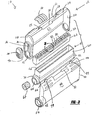
Figure 3 is an exploded perspective view of the tool container in accordance with the present invention. -
Figure 4 is a side elevational view of the tool container ofFigure 2 -
Figure 5 is an enlarged perspective view of the tool holder. -
Figure 6 is a cross-sectional view along line 6-6 ofFigure 5 . - The following description of the preferred embodiment(s) is merely exemplary in nature and is in no way intended to limit the invention, its application, or uses, as defined by the appended claims.
- Turning to
Figures 1 and 2 , a tool container is shown and designated with thereference numeral 10. The tool container includes afirst housing 12 and asecond housing 14. Thehousings Figure 1 , the containers are shown in a closed position wherein alatch 16 locks thehousings tool bit retainer 18 is positioned inside of thehousings - The
housing 12 includes abase 22 which includes a continuouscurved wall 24. Curvedwall 24 includesoffset portions housings Sidewalls curved wall 24. Thesidewalls apertures tool holder 18. Thesidewall 28 includes aflange 34 surrounding aslot 36. Adoor 38 with aprojection 40, which fits intoslot 36, slides within theflange 34. Thedoor 38 is slidable inside the flange to cover a compartment which will be explained later. - The
housing 14 includes abase 44 with acurved wall 46 andsidewalls wall 46 includesoffset portions housings sidewalls apertures housing 14. Thecurved wall 46, likecurved wall 24, includes arail portion 51 for receiving thelatch 16 to lock the housing members together. - The
tool bit retainer 18 includes ahousing portion 60 and atool bit holder 62. Thehousing 60 includes aslot 64 to receive thebit holding portion 62. Also, thehousing portion 60 includes an unitarily formed tube portion 66. The tube portion 66 includes abore 68 which may receive a tool holder or the like.Flanges housings flanges bore 68 is covered by thedoor 38. Thedoor 38 may be opened and closed to expose thebore 68 when the housings are in a closed as well as an opened position. Thus, thebore 68 may be accessed at any time. Also, the bore may include a dampening member, such as a foam plug, to prevent rattling noise from a tool bit. - The
tool bit holder 62 has an overall rectangular configuration. Thetool bit holder 62 is formed from a thermal plastic material. Thus, thetool holder 62 is elastic and may be compressed. Thetool holder 62 includes a plurality ofbore members 80 to receive tool bits. Thetool bit holder 62 fits intoslot 64 of thebit retainer 18 to retain thetool bit holder 62 in thetool bit retainer 18. Each of the plurality ofbores 80 includes at least one, preferably four, projectingmembers 82. The projectingmembers 82 extend radially inward from the circumference of thebore 80. Also, themembers 82 extend axially along the bore. Themembers 82 are unitarily formed with thetool bit holder 62. - As a tool bit is inserted into the
bore 80, it contacts the projectingmembers 82. The projectingmembers 82 compress to enable further insertion of the tool bit into thebore 80. Due to the elastomeric resilience of the material that makes up the projectingmembers 82, the projectingmembers 82 exert a counter force onto the tool bit to retain the tool within thebit holder 62. Thebores 80 may be identical to retain identical bits. Also, the bores may have varying sizes to retain different sizes of tool bits such as drill bits. Further, indicia may be positioned onto the tool holder or bitretainer 18 to identify to the user which tool bit is in thespecific bore 80. - During assembly of the unit, the
apertures housing members flanges bit retainer 18. Due to this type of connection, thehousings bit retainer 18 may be moved independently of thehousing members bit retainer 18 may be moved from a first position, where it is inside ofhousing 12, to a second position angled with respect tohousing 12. Ordinarily, thebit retainer 18 can be moved to approximately a 45° angle with respect to thehousing 12. This allows ready access to the tool bits within the bit retainer. - Also, the
housing members Fig. 4 . Stops can be formed along the hoops defining theapertures flanges tool retainer 18 with respect to thehousings - The description of the invention is merely exemplary in nature and, thus, variations that do not depart from the gist of the invention are intended to be within the scope of the invention as indicated by the appended claims.
Claims (11)
- A tool container (10) comprising:a first housing (12) and a second housing (14);a tool bit retainer (18), said first and second housings rotatably coupled with said tool bit retainer, said first and second housings moving from a closed position surrounding said tool bit retainer prohibiting access to said tool bit retainer to an open position enabling access to said tool bit retainer;said tool bit retainer being independently rotatable with respect to said first and second housings in said open position;said tool bit retainer having at least one member (80, 82) for retaining a tool bit on said tool bit retainer; andsaid tool bit retainer having a compartment (66) which is accessible when said first and second housing are in both said open and closed positions:characterised in that: said compartment is formed by a bore (68) through said pivot and that said bore is covered by a moveable door (38) which may be opened and closed to expose said bore when said first and second housings are closed as well as in an opened position.said tool bit retainer includes a pivot (70, 72) and said first and second housings include openings (30, 32, 52, 54) coupling with said pivot for enabling rotation
- The tool container of Claim 1, wherein said tool bit retainer (18) includes a slot (64) for receiving a tool bit holder (62).
- The tool container of Claim 2, wherein said tool bit holder (62) includes said at least one member (80, 82) for retaining a tool bit.
- The tool container of Claim 3 ,wherein said tool bit holder (62) is manufactured from a thermoplastic.
- The tool container of Claim 4, wherein each member (80, 82) for retaining a tool bit includes a circumferential wall defining a bore (80) and at least one projectiing member (82) extending radially inwardly for contacting a tool bit to retain the tool bit in said bore.
- The tool container of Claim 5, wherein each member (80, 82) for retaining a tool bit includes four projecting members (82).
- The tool container of Claim 1, wherein said first and second housings (12, 14) in said open position form an angle with respect to one another up to about 190° and said tool bit retainer (18) is pivotable along an angle from about 0° to about 45° with respect to said first housing (12).
- The tool container of Claim 5, wherein said at least one projecting member (82) extends axially along said circumferential wall of said bore (80).
- The tool container of Claim 1, wherein a latch (16) locks said first and second housings in said closed position.
- The tool container of any one of the previous claims, wherein said bore comprises a damping member to prevent rattling noise from a tool bit.
- The tool container of claim 10, wherein the damping member is a foam plug.
Applications Claiming Priority (2)
| Application Number | Priority Date | Filing Date | Title |
|---|---|---|---|
| US10/458,134 US6978890B2 (en) | 2003-06-10 | 2003-06-10 | Screwdriver bit package |
| US458134 | 2003-06-10 |
Publications (2)
| Publication Number | Publication Date |
|---|---|
| EP1486296A1 EP1486296A1 (en) | 2004-12-15 |
| EP1486296B1 true EP1486296B1 (en) | 2009-08-05 |
Family
ID=33299634
Family Applications (1)
| Application Number | Title | Priority Date | Filing Date |
|---|---|---|---|
| EP04012740A Expired - Lifetime EP1486296B1 (en) | 2003-06-10 | 2004-05-28 | Screwdriver bit package |
Country Status (5)
| Country | Link |
|---|---|
| US (1) | US6978890B2 (en) |
| EP (1) | EP1486296B1 (en) |
| CN (1) | CN100384596C (en) |
| AT (1) | ATE438487T1 (en) |
| DE (1) | DE602004022356D1 (en) |
Families Citing this family (33)
| Publication number | Priority date | Publication date | Assignee | Title |
|---|---|---|---|---|
| US20050109649A1 (en) * | 2003-11-26 | 2005-05-26 | Natoli Engineering Company, Inc. | Container for holding punches and dies |
| US7322470B2 (en) * | 2004-09-30 | 2008-01-29 | Black & Decker Inc. | Tool container |
| CN2801419Y (en) * | 2005-05-25 | 2006-08-02 | 苏州宝时得电动工具有限公司 | Accessory box |
| TWM316144U (en) * | 2007-01-05 | 2007-08-01 | Jeoutay Liu Ind Co Ltd | Holding structure of tool box |
| TWM329511U (en) * | 2007-06-29 | 2008-04-01 | Ji-Fen Meng | Structure of drive bit storage box |
| DE202007016664U1 (en) * | 2007-12-04 | 2009-04-16 | Emil Lux Gmbh & Co. Kg | Bitbox |
| USD592930S1 (en) * | 2008-08-04 | 2009-05-26 | Yong-Yue Cai | Screwdriver with LED light |
| US8069997B2 (en) * | 2008-09-18 | 2011-12-06 | Chin-Shun Cheng | Portable tool rack |
| US7870956B1 (en) * | 2010-07-07 | 2011-01-18 | Tzu-Chien Wang | Tool storage assembly |
| DE102010032926A1 (en) * | 2010-07-30 | 2012-04-05 | Hazet-Werk Hermann Zerver Gmbh & Co. Kg. | Ratchet box |
| US8469190B1 (en) * | 2012-03-19 | 2013-06-25 | Primaplus Industrial Co., Ltd. | Tool box |
| US9539722B2 (en) | 2012-12-19 | 2017-01-10 | Milwaukee Electric Tool Corporation | Tool storage devices |
| CN203327957U (en) * | 2013-07-08 | 2013-12-11 | 刘秋明 | Electronic cigarette case |
| USD721231S1 (en) | 2013-08-20 | 2015-01-20 | Milwaukee Electric Tool Corporation | Accessory case |
| CN205968920U (en) | 2014-07-22 | 2017-02-22 | 米沃奇电动工具公司 | Tool storage device |
| USD740559S1 (en) | 2014-08-25 | 2015-10-13 | Milwaukee Electric Tool Corporation | Accessory case |
| US9694489B2 (en) | 2014-08-25 | 2017-07-04 | Milwaukee Electric Tool Corporation | Tool bit case with modular components |
| US9254565B1 (en) * | 2014-10-23 | 2016-02-09 | Compass Corporation | Toolbox |
| CN104526666A (en) * | 2014-11-17 | 2015-04-22 | 江门市蓬江区华龙包装材料有限公司 | Tool box of winding machine |
| USD844324S1 (en) | 2015-07-17 | 2019-04-02 | Milwaukee Electric Tool Corporation | Bag |
| USD810435S1 (en) | 2015-07-17 | 2018-02-20 | Milwaukee Electric Tool Corporation | Bag |
| USD834817S1 (en) | 2015-07-17 | 2018-12-04 | Milwaukee Electric Tool Corporation | Bag |
| US9872547B2 (en) | 2015-11-25 | 2018-01-23 | Milwaukee Electric Tool Corporation | Handle assembly for a case |
| USD918688S1 (en) * | 2019-11-25 | 2021-05-11 | Proprietary Technologies, Inc. | Pocket screwdriver half |
| USD927279S1 (en) * | 2020-03-12 | 2021-08-10 | Proprietary Technologies, Inc. | Screwdriver |
| TWI755192B (en) * | 2020-12-08 | 2022-02-11 | 金統立工業股份有限公司 | Tool box |
| CN219170872U (en) | 2021-07-22 | 2023-06-13 | 米沃奇电动工具公司 | Tool accessory holders, tool systems and tool accessory storage systems |
| USD1063376S1 (en) | 2022-06-08 | 2025-02-25 | Yeti Coolers, Llc | Container |
| USD1024557S1 (en) | 2022-06-08 | 2024-04-30 | Yeti Coolers, Llc | Container |
| US11912477B2 (en) | 2022-06-08 | 2024-02-27 | Yeti Coolers, Llc | Container with handle and latching system |
| USD1036116S1 (en) | 2022-06-08 | 2024-07-23 | Yeti Coolers, Llc | Container |
| USD1036119S1 (en) | 2022-11-30 | 2024-07-23 | Yeti Coolers, Llc | Container |
| US11751673B1 (en) * | 2022-12-18 | 2023-09-12 | Michael H Panosian | Locking screwdriver holder |
Family Cites Families (9)
| Publication number | Priority date | Publication date | Assignee | Title |
|---|---|---|---|---|
| EP0313733A1 (en) | 1987-08-21 | 1989-05-03 | Firma Georg Knoblauch | Cassette for storing oblong objects |
| DE9013289U1 (en) | 1990-09-20 | 1992-01-30 | Wera-Werk Hermann Werner Gmbh & Co, 5600 Wuppertal | Box for holding screwdriver bits |
| DE9205913U1 (en) | 1992-05-01 | 1993-08-26 | Emil Lux GmbH & Co KG, 42929 Wermelskirchen | Storage box |
| DE9419983U1 (en) | 1994-12-14 | 1995-03-16 | Mesenhöller, Hans, 42855 Remscheid | Tool carriers for attachments, e.g. Screwdriver bits |
| US5951385A (en) * | 1996-08-08 | 1999-09-14 | Credo Tool Company | Drill bit case and drill sharpener package |
| IT237482Y1 (en) | 1997-05-09 | 2000-09-13 | Hardware Ind Mfg S R L | CONTAINING BOX OF BLADES FOR ALTERNATIVE SAW |
| DE29913188U1 (en) * | 1999-07-28 | 1999-11-18 | Drilbox Georg Knoblauch GmbH, 89537 Giengen | Toolbox |
| CN2425744Y (en) * | 2000-05-29 | 2001-04-04 | 进业(天津)轻工制品有限公司 | Convenient hardware tools box |
| US6547074B1 (en) * | 2001-11-09 | 2003-04-15 | Chang-Ying Chen | Tool box having pivotal inner frames |
-
2003
- 2003-06-10 US US10/458,134 patent/US6978890B2/en not_active Expired - Fee Related
-
2004
- 2004-05-28 DE DE602004022356T patent/DE602004022356D1/en not_active Expired - Fee Related
- 2004-05-28 AT AT04012740T patent/ATE438487T1/en not_active IP Right Cessation
- 2004-05-28 EP EP04012740A patent/EP1486296B1/en not_active Expired - Lifetime
- 2004-06-10 CN CNB2004100639666A patent/CN100384596C/en not_active Expired - Fee Related
Also Published As
| Publication number | Publication date |
|---|---|
| CN1572438A (en) | 2005-02-02 |
| US6978890B2 (en) | 2005-12-27 |
| US20040256265A1 (en) | 2004-12-23 |
| CN100384596C (en) | 2008-04-30 |
| EP1486296A1 (en) | 2004-12-15 |
| ATE438487T1 (en) | 2009-08-15 |
| DE602004022356D1 (en) | 2009-09-17 |
Similar Documents
| Publication | Publication Date | Title |
|---|---|---|
| US6978890B2 (en) | Screwdriver bit package | |
| AU646350B2 (en) | Bit storage means for drill press | |
| CN104884211B (en) | Toolbox | |
| US5938028A (en) | Tool holder for hexagonal wrenches | |
| JP4091843B2 (en) | Storage device for one or more tools | |
| CA2298505A1 (en) | Toolboxes and tool cases with pivotable component holder | |
| US20060226042A1 (en) | Storage case | |
| CA2291314A1 (en) | End cap and mounting support combination | |
| US5271501A (en) | Toolbox | |
| KR20030030848A (en) | damping device of open-close member and vessel holder and door for vehicle having the same | |
| WO2001083325A3 (en) | Security box for recorded media | |
| EP1004514A3 (en) | Storage device with improvements | |
| US7527166B2 (en) | Storage apparatus | |
| CN116419692B (en) | Sliding Rotary Storage Unit | |
| GB2276758A (en) | Waterproof casing for portable electronic appartus having sliding battery cover | |
| US7066089B1 (en) | Automatically re-inked stamp | |
| US5779101A (en) | Portable carrier for aerosol containers and method therefor | |
| US5934115A (en) | Circuit breaker panelboard lock assembly | |
| US6725503B1 (en) | Door closer having dual operating directions | |
| US20040207298A1 (en) | Work storage unit | |
| EP1723710B1 (en) | Apparatus for retention of battery in charger | |
| JP4231223B2 (en) | Sliding door handle | |
| CN212919316U (en) | Tool kit with positioning and supporting functions | |
| KR100612562B1 (en) | Opening/closing assembly and apparatus for doors | |
| JP4477485B2 (en) | Cap device |
Legal Events
| Date | Code | Title | Description |
|---|---|---|---|
| PUAI | Public reference made under article 153(3) epc to a published international application that has entered the european phase |
Free format text: ORIGINAL CODE: 0009012 |
|
| AK | Designated contracting states |
Kind code of ref document: A1 Designated state(s): AT BE BG CH CY CZ DE DK EE ES FI FR GB GR HU IE IT LI LU MC NL PL PT RO SE SI SK TR |
|
| AX | Request for extension of the european patent |
Extension state: AL HR LT LV MK |
|
| 17P | Request for examination filed |
Effective date: 20050125 |
|
| AKX | Designation fees paid |
Designated state(s): AT BE BG CH CY CZ DE DK EE ES FI FR GB GR HU IE IT LI LU MC NL PL PT RO SE SI SK TR |
|
| GRAP | Despatch of communication of intention to grant a patent |
Free format text: ORIGINAL CODE: EPIDOSNIGR1 |
|
| GRAC | Information related to communication of intention to grant a patent modified |
Free format text: ORIGINAL CODE: EPIDOSCIGR1 |
|
| GRAS | Grant fee paid |
Free format text: ORIGINAL CODE: EPIDOSNIGR3 |
|
| GRAA | (expected) grant |
Free format text: ORIGINAL CODE: 0009210 |
|
| AK | Designated contracting states |
Kind code of ref document: B1 Designated state(s): AT BE BG CH CY CZ DE DK EE ES FI FR GB GR HU IE IT LI LU MC NL PL PT RO SE SI SK TR |
|
| REG | Reference to a national code |
Ref country code: GB Ref legal event code: FG4D |
|
| REG | Reference to a national code |
Ref country code: CH Ref legal event code: EP |
|
| REG | Reference to a national code |
Ref country code: IE Ref legal event code: FG4D |
|
| REF | Corresponds to: |
Ref document number: 602004022356 Country of ref document: DE Date of ref document: 20090917 Kind code of ref document: P |
|
| PG25 | Lapsed in a contracting state [announced via postgrant information from national office to epo] |
Ref country code: AT Free format text: LAPSE BECAUSE OF FAILURE TO SUBMIT A TRANSLATION OF THE DESCRIPTION OR TO PAY THE FEE WITHIN THE PRESCRIBED TIME-LIMIT Effective date: 20090805 Ref country code: FI Free format text: LAPSE BECAUSE OF FAILURE TO SUBMIT A TRANSLATION OF THE DESCRIPTION OR TO PAY THE FEE WITHIN THE PRESCRIBED TIME-LIMIT Effective date: 20090805 Ref country code: SE Free format text: LAPSE BECAUSE OF FAILURE TO SUBMIT A TRANSLATION OF THE DESCRIPTION OR TO PAY THE FEE WITHIN THE PRESCRIBED TIME-LIMIT Effective date: 20090805 Ref country code: ES Free format text: LAPSE BECAUSE OF FAILURE TO SUBMIT A TRANSLATION OF THE DESCRIPTION OR TO PAY THE FEE WITHIN THE PRESCRIBED TIME-LIMIT Effective date: 20091116 |
|
| NLV1 | Nl: lapsed or annulled due to failure to fulfill the requirements of art. 29p and 29m of the patents act | ||
| PG25 | Lapsed in a contracting state [announced via postgrant information from national office to epo] |
Ref country code: NL Free format text: LAPSE BECAUSE OF FAILURE TO SUBMIT A TRANSLATION OF THE DESCRIPTION OR TO PAY THE FEE WITHIN THE PRESCRIBED TIME-LIMIT Effective date: 20090805 Ref country code: PL Free format text: LAPSE BECAUSE OF FAILURE TO SUBMIT A TRANSLATION OF THE DESCRIPTION OR TO PAY THE FEE WITHIN THE PRESCRIBED TIME-LIMIT Effective date: 20090805 Ref country code: SI Free format text: LAPSE BECAUSE OF FAILURE TO SUBMIT A TRANSLATION OF THE DESCRIPTION OR TO PAY THE FEE WITHIN THE PRESCRIBED TIME-LIMIT Effective date: 20090805 |
|
| PG25 | Lapsed in a contracting state [announced via postgrant information from national office to epo] |
Ref country code: BG Free format text: LAPSE BECAUSE OF FAILURE TO SUBMIT A TRANSLATION OF THE DESCRIPTION OR TO PAY THE FEE WITHIN THE PRESCRIBED TIME-LIMIT Effective date: 20091105 Ref country code: PT Free format text: LAPSE BECAUSE OF FAILURE TO SUBMIT A TRANSLATION OF THE DESCRIPTION OR TO PAY THE FEE WITHIN THE PRESCRIBED TIME-LIMIT Effective date: 20091205 |
|
| PG25 | Lapsed in a contracting state [announced via postgrant information from national office to epo] |
Ref country code: EE Free format text: LAPSE BECAUSE OF FAILURE TO SUBMIT A TRANSLATION OF THE DESCRIPTION OR TO PAY THE FEE WITHIN THE PRESCRIBED TIME-LIMIT Effective date: 20090805 Ref country code: DK Free format text: LAPSE BECAUSE OF FAILURE TO SUBMIT A TRANSLATION OF THE DESCRIPTION OR TO PAY THE FEE WITHIN THE PRESCRIBED TIME-LIMIT Effective date: 20090805 Ref country code: RO Free format text: LAPSE BECAUSE OF FAILURE TO SUBMIT A TRANSLATION OF THE DESCRIPTION OR TO PAY THE FEE WITHIN THE PRESCRIBED TIME-LIMIT Effective date: 20090805 Ref country code: CZ Free format text: LAPSE BECAUSE OF FAILURE TO SUBMIT A TRANSLATION OF THE DESCRIPTION OR TO PAY THE FEE WITHIN THE PRESCRIBED TIME-LIMIT Effective date: 20090805 |
|
| PG25 | Lapsed in a contracting state [announced via postgrant information from national office to epo] |
Ref country code: SK Free format text: LAPSE BECAUSE OF FAILURE TO SUBMIT A TRANSLATION OF THE DESCRIPTION OR TO PAY THE FEE WITHIN THE PRESCRIBED TIME-LIMIT Effective date: 20090805 |
|
| PLBE | No opposition filed within time limit |
Free format text: ORIGINAL CODE: 0009261 |
|
| STAA | Information on the status of an ep patent application or granted ep patent |
Free format text: STATUS: NO OPPOSITION FILED WITHIN TIME LIMIT |
|
| PG25 | Lapsed in a contracting state [announced via postgrant information from national office to epo] |
Ref country code: BE Free format text: LAPSE BECAUSE OF FAILURE TO SUBMIT A TRANSLATION OF THE DESCRIPTION OR TO PAY THE FEE WITHIN THE PRESCRIBED TIME-LIMIT Effective date: 20090805 |
|
| 26N | No opposition filed |
Effective date: 20100507 |
|
| PG25 | Lapsed in a contracting state [announced via postgrant information from national office to epo] |
Ref country code: GR Free format text: LAPSE BECAUSE OF FAILURE TO SUBMIT A TRANSLATION OF THE DESCRIPTION OR TO PAY THE FEE WITHIN THE PRESCRIBED TIME-LIMIT Effective date: 20091106 |
|
| PG25 | Lapsed in a contracting state [announced via postgrant information from national office to epo] |
Ref country code: MC Free format text: LAPSE BECAUSE OF NON-PAYMENT OF DUE FEES Effective date: 20100531 |
|
| REG | Reference to a national code |
Ref country code: CH Ref legal event code: PL |
|
| GBPC | Gb: european patent ceased through non-payment of renewal fee |
Effective date: 20100528 |
|
| REG | Reference to a national code |
Ref country code: FR Ref legal event code: ST Effective date: 20110131 |
|
| PG25 | Lapsed in a contracting state [announced via postgrant information from national office to epo] |
Ref country code: LI Free format text: LAPSE BECAUSE OF NON-PAYMENT OF DUE FEES Effective date: 20100531 Ref country code: CH Free format text: LAPSE BECAUSE OF NON-PAYMENT OF DUE FEES Effective date: 20100531 |
|
| PG25 | Lapsed in a contracting state [announced via postgrant information from national office to epo] |
Ref country code: IT Free format text: LAPSE BECAUSE OF FAILURE TO SUBMIT A TRANSLATION OF THE DESCRIPTION OR TO PAY THE FEE WITHIN THE PRESCRIBED TIME-LIMIT Effective date: 20090805 |
|
| PG25 | Lapsed in a contracting state [announced via postgrant information from national office to epo] |
Ref country code: DE Free format text: LAPSE BECAUSE OF NON-PAYMENT OF DUE FEES Effective date: 20101201 Ref country code: IE Free format text: LAPSE BECAUSE OF NON-PAYMENT OF DUE FEES Effective date: 20100528 |
|
| PG25 | Lapsed in a contracting state [announced via postgrant information from national office to epo] |
Ref country code: FR Free format text: LAPSE BECAUSE OF NON-PAYMENT OF DUE FEES Effective date: 20100531 |
|
| PG25 | Lapsed in a contracting state [announced via postgrant information from national office to epo] |
Ref country code: GB Free format text: LAPSE BECAUSE OF NON-PAYMENT OF DUE FEES Effective date: 20100528 |
|
| PG25 | Lapsed in a contracting state [announced via postgrant information from national office to epo] |
Ref country code: CY Free format text: LAPSE BECAUSE OF FAILURE TO SUBMIT A TRANSLATION OF THE DESCRIPTION OR TO PAY THE FEE WITHIN THE PRESCRIBED TIME-LIMIT Effective date: 20090805 |
|
| PG25 | Lapsed in a contracting state [announced via postgrant information from national office to epo] |
Ref country code: HU Free format text: LAPSE BECAUSE OF FAILURE TO SUBMIT A TRANSLATION OF THE DESCRIPTION OR TO PAY THE FEE WITHIN THE PRESCRIBED TIME-LIMIT Effective date: 20100206 Ref country code: LU Free format text: LAPSE BECAUSE OF NON-PAYMENT OF DUE FEES Effective date: 20100528 |
|
| PG25 | Lapsed in a contracting state [announced via postgrant information from national office to epo] |
Ref country code: TR Free format text: LAPSE BECAUSE OF FAILURE TO SUBMIT A TRANSLATION OF THE DESCRIPTION OR TO PAY THE FEE WITHIN THE PRESCRIBED TIME-LIMIT Effective date: 20090805 |