EP1486291B1 - Fixture having integrated datum locators - Google Patents
Fixture having integrated datum locators Download PDFInfo
- Publication number
- EP1486291B1 EP1486291B1 EP04253167A EP04253167A EP1486291B1 EP 1486291 B1 EP1486291 B1 EP 1486291B1 EP 04253167 A EP04253167 A EP 04253167A EP 04253167 A EP04253167 A EP 04253167A EP 1486291 B1 EP1486291 B1 EP 1486291B1
- Authority
- EP
- European Patent Office
- Prior art keywords
- fixture
- component
- blade
- components
- datum surfaces
- Prior art date
- Legal status (The legal status is an assumption and is not a legal conclusion. Google has not performed a legal analysis and makes no representation as to the accuracy of the status listed.)
- Expired - Lifetime
Links
- 238000004519 manufacturing process Methods 0.000 claims description 38
- 238000003754 machining Methods 0.000 claims description 33
- 238000005520 cutting process Methods 0.000 claims description 6
- 239000012530 fluid Substances 0.000 claims description 3
- 238000000034 method Methods 0.000 description 4
- 230000014759 maintenance of location Effects 0.000 description 2
- 229910001369 Brass Inorganic materials 0.000 description 1
- 241001071864 Lethrinus laticaudis Species 0.000 description 1
- 239000003082 abrasive agent Substances 0.000 description 1
- 239000000654 additive Substances 0.000 description 1
- 230000000996 additive effect Effects 0.000 description 1
- 239000010951 brass Substances 0.000 description 1
- 230000003247 decreasing effect Effects 0.000 description 1
- 230000000694 effects Effects 0.000 description 1
- 238000007689 inspection Methods 0.000 description 1
- 238000009434 installation Methods 0.000 description 1
- 238000002360 preparation method Methods 0.000 description 1
- 238000007493 shaping process Methods 0.000 description 1
- 230000008016 vaporization Effects 0.000 description 1
Images


Classifications
-
- B—PERFORMING OPERATIONS; TRANSPORTING
- B23—MACHINE TOOLS; METAL-WORKING NOT OTHERWISE PROVIDED FOR
- B23Q—DETAILS, COMPONENTS, OR ACCESSORIES FOR MACHINE TOOLS, e.g. ARRANGEMENTS FOR COPYING OR CONTROLLING; MACHINE TOOLS IN GENERAL CHARACTERISED BY THE CONSTRUCTION OF PARTICULAR DETAILS OR COMPONENTS; COMBINATIONS OR ASSOCIATIONS OF METAL-WORKING MACHINES, NOT DIRECTED TO A PARTICULAR RESULT
- B23Q3/00—Devices holding, supporting, or positioning work or tools, of a kind normally removable from the machine
- B23Q3/02—Devices holding, supporting, or positioning work or tools, of a kind normally removable from the machine for mounting on a work-table, tool-slide, or analogous part
- B23Q3/06—Work-clamping means
- B23Q3/062—Work-clamping means adapted for holding workpieces having a special form or being made from a special material
- B23Q3/063—Work-clamping means adapted for holding workpieces having a special form or being made from a special material for holding turbine blades
-
- B—PERFORMING OPERATIONS; TRANSPORTING
- B25—HAND TOOLS; PORTABLE POWER-DRIVEN TOOLS; MANIPULATORS
- B25B—TOOLS OR BENCH DEVICES NOT OTHERWISE PROVIDED FOR, FOR FASTENING, CONNECTING, DISENGAGING OR HOLDING
- B25B5/00—Clamps
- B25B5/003—Combinations of clamps
-
- B—PERFORMING OPERATIONS; TRANSPORTING
- B25—HAND TOOLS; PORTABLE POWER-DRIVEN TOOLS; MANIPULATORS
- B25B—TOOLS OR BENCH DEVICES NOT OTHERWISE PROVIDED FOR, FOR FASTENING, CONNECTING, DISENGAGING OR HOLDING
- B25B5/00—Clamps
- B25B5/14—Clamps for work of special profile
-
- Y—GENERAL TAGGING OF NEW TECHNOLOGICAL DEVELOPMENTS; GENERAL TAGGING OF CROSS-SECTIONAL TECHNOLOGIES SPANNING OVER SEVERAL SECTIONS OF THE IPC; TECHNICAL SUBJECTS COVERED BY FORMER USPC CROSS-REFERENCE ART COLLECTIONS [XRACs] AND DIGESTS
- Y10—TECHNICAL SUBJECTS COVERED BY FORMER USPC
- Y10T—TECHNICAL SUBJECTS COVERED BY FORMER US CLASSIFICATION
- Y10T29/00—Metal working
- Y10T29/49—Method of mechanical manufacture
- Y10T29/49316—Impeller making
- Y10T29/49336—Blade making
-
- Y—GENERAL TAGGING OF NEW TECHNOLOGICAL DEVELOPMENTS; GENERAL TAGGING OF CROSS-SECTIONAL TECHNOLOGIES SPANNING OVER SEVERAL SECTIONS OF THE IPC; TECHNICAL SUBJECTS COVERED BY FORMER USPC CROSS-REFERENCE ART COLLECTIONS [XRACs] AND DIGESTS
- Y10—TECHNICAL SUBJECTS COVERED BY FORMER USPC
- Y10T—TECHNICAL SUBJECTS COVERED BY FORMER US CLASSIFICATION
- Y10T29/00—Metal working
- Y10T29/49—Method of mechanical manufacture
- Y10T29/49826—Assembling or joining
- Y10T29/49895—Associating parts by use of aligning means [e.g., use of a drift pin or a "fixture"]
-
- Y—GENERAL TAGGING OF NEW TECHNOLOGICAL DEVELOPMENTS; GENERAL TAGGING OF CROSS-SECTIONAL TECHNOLOGIES SPANNING OVER SEVERAL SECTIONS OF THE IPC; TECHNICAL SUBJECTS COVERED BY FORMER USPC CROSS-REFERENCE ART COLLECTIONS [XRACs] AND DIGESTS
- Y10—TECHNICAL SUBJECTS COVERED BY FORMER USPC
- Y10T—TECHNICAL SUBJECTS COVERED BY FORMER US CLASSIFICATION
- Y10T29/00—Metal working
- Y10T29/49—Method of mechanical manufacture
- Y10T29/49998—Work holding
-
- Y—GENERAL TAGGING OF NEW TECHNOLOGICAL DEVELOPMENTS; GENERAL TAGGING OF CROSS-SECTIONAL TECHNOLOGIES SPANNING OVER SEVERAL SECTIONS OF THE IPC; TECHNICAL SUBJECTS COVERED BY FORMER USPC CROSS-REFERENCE ART COLLECTIONS [XRACs] AND DIGESTS
- Y10—TECHNICAL SUBJECTS COVERED BY FORMER USPC
- Y10T—TECHNICAL SUBJECTS COVERED BY FORMER US CLASSIFICATION
- Y10T29/00—Metal working
- Y10T29/53—Means to assemble or disassemble
- Y10T29/53961—Means to assemble or disassemble with work-holder for assembly
-
- Y—GENERAL TAGGING OF NEW TECHNOLOGICAL DEVELOPMENTS; GENERAL TAGGING OF CROSS-SECTIONAL TECHNOLOGIES SPANNING OVER SEVERAL SECTIONS OF THE IPC; TECHNICAL SUBJECTS COVERED BY FORMER USPC CROSS-REFERENCE ART COLLECTIONS [XRACs] AND DIGESTS
- Y10—TECHNICAL SUBJECTS COVERED BY FORMER USPC
- Y10T—TECHNICAL SUBJECTS COVERED BY FORMER US CLASSIFICATION
- Y10T29/00—Metal working
- Y10T29/53—Means to assemble or disassemble
- Y10T29/53978—Means to assemble or disassemble including means to relatively position plural work parts
Definitions
- the present invention relates generally to fixtures having close tolerance datum locators, and more particularly to fixtures having integrated close tolerance datum locators used for providing multiple manufacturing operations on multiple parts at a single manufacturing station.
- Such a fixture is for example known from the document FR-A-2604936 .
- fixture In the manufacture of components, especially those machined to close tolerances further having intricate and complex shapes, such as gas turbine engine blades and vanes, tooling fixtures adapted to secure the components are required.
- Such fixtures which represent a manufacturing station, typically contain three reference contact surfaces machined to even closer tolerance, referred to as datums, to precisely position and secure the component for the manufacturing step that is performed at the manufacturing station. Multiple stations are usually required to manufacture the component, typically one station is required for each manufacturing step. Although closer datum tolerances may be maintained in the fixtures, additive tolerance build-up is almost invariably introduced at each of the manufacturing stations resulting in components having increased dimensional deviation from that desired. Minimizing the number of fixtures required to manufacture the component is desirable due to component tolerance build-up and the high cost associated with fixture fabrication.
- What is desired is an integral fixture at a single manufacturing station having at least two sets of close tolerance datum surfaces that can secure at least two parts for simultaneous multiple machining operations.
- This invention pertains to a fixture adapted to precisely position at least two components at a predetermined distance and orientation therebetween for permitting a machining means directed along the fixture to simultaneously perform at least one machining operation to the at least two components.
- the fixture incorporates a backbone having a first portion for securing a first component and a second portion for securing a second component.
- the first and second portions each further including an integral set of three precisely positioned datum surfaces formed therein for precisely positioning the first and second components.
- An advantage of the present invention is that it provides a fixture that reduces component tolerance build-up introduced during the manufacture of components due to reduction of the number of fixtures required.
- a further advantage of the present invention is that it provides a fixture that reduces the number of manufacturing stations required to manufacture a component.
- Still another advantage of the present invention is that it provides a fixture that reduces the number of machining tools required to manufacture a component.
- Yet another advantage of the present invention is that rework of out-of-tolerance articles is reduced.
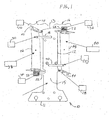
- Fig. 1 illustrates a front view of the preferred form of the invention, wherein 10 generally designates a fixture constructed in accordance with and embodying the present invention.
- Fixture 10 represents a single manufacturing station and includes a backbone 12 having a first portion 14 and a second portion 16 for positioning a first blade 38 and a second blade 40, respectively, therein.
- First portion 14 includes datum surfaces 26, 30 and 34 to precisely position first blade 38
- second portion 16 includes datum surfaces 28, 32 and 36 to precisely position second blade 40 in preparation of multiple machining operations at a single manufacturing station as will be discussed in more detail below.
- fixture 10 includes a proximal end 11 for securing fixture 10 at its respective manufacturing station while blades 38, 40 are being machined.
- Lobe 22 terminates at datum surface 34 which contacts and precisely positions a base 50, also referred as dovetail, of first blade 38.
- a finger 18 extends outwardly from a front face 15 that is opposite that of back face 17 of backbone 12 and further extends outwardly from backbone 12 along first portion 14, terminating at datum surface 30, which contacts and precisely positions a vent portion 46 of first blade 38.
- first blade 38 is collectively positioned against datum surfaces 26, 30 and 34, a clamping means (not shown) secures first blade 38 in this position during manufacturing operations at this station.
- Second portion 16 of backbone 12 shall now be discussed.
- Adjacent proximal end 11 along second portion 16 of backbone 12 is located datum surface 28 which contacts and precisely positions a shroud 44 of second blade 40.
- a finger 20 extends outwardly from front face 15 of backbone 12 and further extends outwardly from backbone 12 along second portion 16, terminating at datum surface 32, which contacts and precisely positions a vent portion 48 of second blade 40.
- a lobe 24 that extends outwardly from backbone 12.
- Lobe 24 terminates at datum surface 36 which contacts and precisely positions a base 52 of second blade 40.
- first and second blades 38, 40 are identical parts.
- datum surfaces 26, 30 and 34 each correspond to datum surfaces 28, 32 and 36. That is to say, collectively, each of these sets of datum surfaces contacts and precisely positions the identical portions of first and second blades 38, 40 at a predetermined spacing and orientation from each other.
- Each blade 38, 40 includes an axis 54, 56 which spans the center of the blade from dovetail 50 to shroud 42.
- the difference in orientation between first blade 38 and second blade 40 is that second blade 40 is rotated 180 degrees about its axis 56 with respect to first blade 38 that passes through the middle of second blade 40. This orientation is apparent by inspection of the orientations of first blade 38 and second blade 40 in Figs. 1-3 .
- first blade 38 matches the orientation of second blade 40.
- fixture 10 Utilizing advances in tool forming methods, such as wire electro discharge machining ("EDM”) which uses a spool of wire, typically brass, fixture 10 is shaped by vaporizing a desired path along the profile of fixture 10 to form integral datum surfaces 26, 28, 30, 32, 34 and 36, each datum surface having tolerances of +/- .0001 of an inch from the nominal position.
- EDM wire electro discharge machining
- designations A, B and C represent three identical blades introduced sequentially into fixture 10 at different times during the manufacturing process.
- Designations A' and B' represent blades A and B, respectively, rotated 180 degrees from the orientation as initially installed in first portion 14 of fixture 10, as previously discussed.
- clamping means include at least one set of arms controllably actuated by hydraulic, pneumatic, spring retention or any number of other mechanical arrangement providing a controllable compressive force to opposed sides of blade A and backbone 12 fixture 10 so that blade A and fixture 10 are directed toward one another to ensure that blade A is located against the respective datum surfaces 26, 30 and 34 of the first portion 14 of the fixture 10.
- Two sets of clamping means are typically employed to locate and secure blade A in position against datum surfaces 26, 30 and 34.
- a hydraulically-powered clamping means actuated by the use of high pressure hydraulic fluid is preferably employed to locate and secure the portion of blade A adjacent shroud 42 against datum surfaces 26 and 30 due to the ability of the clamping means to apply elevated levels of compressive forces. Such elevated compressive forces are required to immobilize this portion of blade A with respect to datum surfaces 26 and 30, since these datum surfaces are adjacent shroud 42 which is machined as discussed below. In other words, the clamping means must exert sufficient compressive forces between datum surfaces 26 and 30 and blade 38 to withstand the reactive forces created by the machining of shroud 42. Similarly, a second clamping means is preferably employed to likewise locate and secure base 50 against datum 34.
- machining means 58 such as a grinding wheel, is directed toward fixture 10 along a travel direction 60 so that a machining portion 62 formed in machining means 58 performs a machining operation on a base 66 of blade A.
- the operator opens clamping means securing blade A and removes blade A from first portion 14.
- the operator then rotates blade A 180 degrees as previously discussed so that blade A now becomes blade A' and installs blade A' as shown in Fig. 5 , which includes positioning and securing blade A' along second portion 16 of fixture 10 against datum surfaces 28, 32 and 36 with clamping means as previously discussed.
- operator installs blade B along first portion 14 of fixture 10 in a similar manner to installing blade A along first portion 14 of fixture 10.
- machining means 58 is again directed toward fixture 10 along travel direction 60 so that simultaneous machining operations are performed to both blades A' and B.
- Machining portion 62 performs a machining operation on a shroud 68 of blade B
- a machining portion 64 formed in machining means 58 performs a machining operation on a base 70 of blade A'.
- machining means 58 is again directed toward fixture 10 along travel direction 60 so that simultaneous machining operations are performed to both blades B' and C. That is, machining portion 62 performs a machining operation on a shroud 72 of blade C, and machining portion 64 performs a machining operation on a base 74 of blade B'. Additional blades can be machined utilizing this method.
- first and second blades 38, 40 are the same part in the preferred embodiment, it is apparent to one skilled in the art that these components need not be identical. That is to say, it may be possible to further add datum surfaces along first and second portions 14, 16 of backbone 12 to additionally accommodate blades of different lengths, preferably configured for machining operations utilizing the same machining means 58. Similarly, although the present invention is directed to fixtures for securing turbine rotor blades, it is apparent that any number of components capable of being located by datum surfaces may be employed.
- the present invention is directed to a machining means such as a grinding wheel, any cutting blades, abrasives, high pressure fluid cutting streams, high temperature or high energy cutting beams or any other manufacturing methods that can be utilized to effect shaping of a component is contemplated.
- a fixture securing two components it is apparent that the fixture could be configured to accommodate more than two components by either widening the fixture to additionally include, for example, third and fourth portions to secure third and fourth components, respectively, or to "piggy back" a second fixture substantially identical to the first fixture (the fixture of the present invention) wherein the first and second fixtures are integral with respect to each other and aligned to receive machining means 58.
- the order of installation and/or removal of the components from the fixture by the operator, or by an automated system is not critical and may be performed in any order so long as the components are secured prior to the machining process.
Landscapes
- Engineering & Computer Science (AREA)
- Mechanical Engineering (AREA)
- Jigs For Machine Tools (AREA)
- Electrical Discharge Machining, Electrochemical Machining, And Combined Machining (AREA)
- Constituent Portions Of Griding Lathes, Driving, Sensing And Control (AREA)
Description
- The present invention relates generally to fixtures having close tolerance datum locators, and more particularly to fixtures having integrated close tolerance datum locators used for providing multiple manufacturing operations on multiple parts at a single manufacturing station.
- Such a fixture is for example known from the document
FR-A-2604936 - In the manufacture of components, especially those machined to close tolerances further having intricate and complex shapes, such as gas turbine engine blades and vanes, tooling fixtures adapted to secure the components are required. Such fixtures, which represent a manufacturing station, typically contain three reference contact surfaces machined to even closer tolerance, referred to as datums, to precisely position and secure the component for the manufacturing step that is performed at the manufacturing station. Multiple stations are usually required to manufacture the component, typically one station is required for each manufacturing step. Although closer datum tolerances may be maintained in the fixtures, additive tolerance build-up is almost invariably introduced at each of the manufacturing stations resulting in components having increased dimensional deviation from that desired. Minimizing the number of fixtures required to manufacture the component is desirable due to component tolerance build-up and the high cost associated with fixture fabrication.
- What is desired is an integral fixture at a single manufacturing station having at least two sets of close tolerance datum surfaces that can secure at least two parts for simultaneous multiple machining operations.
- This invention pertains to a fixture adapted to precisely position at least two components at a predetermined distance and orientation therebetween for permitting a machining means directed along the fixture to simultaneously perform at least one machining operation to the at least two components. The fixture incorporates a backbone having a first portion for securing a first component and a second portion for securing a second component. The first and second portions each further including an integral set of three precisely positioned datum surfaces formed therein for precisely positioning the first and second components.
- An advantage of the present invention is that it provides a fixture that reduces component tolerance build-up introduced during the manufacture of components due to reduction of the number of fixtures required.
- A further advantage of the present invention is that it provides a fixture that reduces the number of manufacturing stations required to manufacture a component.
- Still another advantage of the present invention is that it provides a fixture that reduces the number of machining tools required to manufacture a component.
- Yet another advantage of the present invention is that rework of out-of-tolerance articles is reduced.
- Among the advantages and objects of the present invention is to provide a fixture adaptable for multiple components to reduce the number of fixtures required for manufacture of components.
- Other features and advantages of the present invention will be apparent from the following more detailed description of the preferred embodiment, taken in conjunction with the accompanying drawings which illustrate, by way of example, the principles of the invention, and in which:
-
Fig. 1 is a front view of a fixture of the present invention securing two components for manufacture; -
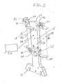
Fig. 2 is a perspective view of the fixture inFig. 1 ; -
Fig. 3 is a back view of the fixture inFig. 1 ; -
Fig. 4 is a perspective view of a first manufacturing sequence wherein the fixture is securing one component; -
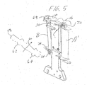
Fig. 5 is a perspective view of a subsequent manufacturing sequence wherein the fixture is securing two components; and -
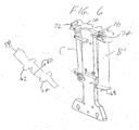
Fig. 6 is a perspective view of a still subsequent manufacturing sequence wherein the fixture is securing two components. - Wherever possible, the same reference numbers will be used throughout the drawings to refer to the same or like parts.
- Referring to the drawings,
Fig. 1 illustrates a front view of the preferred form of the invention, wherein 10 generally designates a fixture constructed in accordance with and embodying the present invention. Fixture 10 represents a single manufacturing station and includes abackbone 12 having afirst portion 14 and asecond portion 16 for positioning afirst blade 38 and asecond blade 40, respectively, therein.First portion 14 includesdatum surfaces first blade 38, andsecond portion 16 includesdatum surfaces second blade 40 in preparation of multiple machining operations at a single manufacturing station as will be discussed in more detail below. - Referring to
Figs. 1 and2 ,fixture 10 includes a proximal end 11 for securingfixture 10 at its respective manufacturing station whileblades lobe 22 extends outwardly frombackbone 12.Lobe 22 terminates atdatum surface 34 which contacts and precisely positions abase 50, also referred as dovetail, offirst blade 38. Further proceeding alongbackbone 12 in a direction toward itsdistal end 13, afinger 18 extends outwardly from afront face 15 that is opposite that ofback face 17 ofbackbone 12 and further extends outwardly frombackbone 12 alongfirst portion 14, terminating atdatum surface 30, which contacts and precisely positions avent portion 46 offirst blade 38. Further proceeding alongbackbone 12 in a direction towarddistal end 13,datum surface 26 which is located adjacentdistal end 13 alongfirst portion 14 contacts and precisely positions ashroud 42 offirst blade 38. Oncefirst blade 38 is collectively positioned againstdatum surfaces first blade 38 in this position during manufacturing operations at this station. -
Second portion 16 ofbackbone 12 shall now be discussed. Adjacent proximal end 11 alongsecond portion 16 ofbackbone 12 is locateddatum surface 28 which contacts and precisely positions ashroud 44 ofsecond blade 40. Further proceeding alongbackbone 12 in a direction towarddistal end 13, afinger 20 extends outwardly fromfront face 15 ofbackbone 12 and further extends outwardly frombackbone 12 alongsecond portion 16, terminating atdatum surface 32, which contacts and precisely positions avent portion 48 ofsecond blade 40. Further proceeding alongbackbone 12 in a direction towarddistal end 13, adjacentdistal end 13 alongsecond portion 16 is located alobe 24 that extends outwardly frombackbone 12.Lobe 24 terminates atdatum surface 36 which contacts and precisely positions abase 52 ofsecond blade 40. Oncesecond blade 40 is collectively positioned againstdatum surfaces second blade 40 in this position during manufacturing operations at this station. - In the preferred embodiment, first and
second blades datum surfaces datum surfaces second blades blade axis dovetail 50 toshroud 42. The difference in orientation betweenfirst blade 38 andsecond blade 40 is thatsecond blade 40 is rotated 180 degrees about itsaxis 56 with respect tofirst blade 38 that passes through the middle ofsecond blade 40. This orientation is apparent by inspection of the orientations offirst blade 38 andsecond blade 40 inFigs. 1-3 . Similarly, by rotatingfirst blade 38 180 degrees about afirst axis 54 that passes through the middle offirst blade 38,first blade 38 matches the orientation ofsecond blade 40. - Utilizing advances in tool forming methods, such as wire electro discharge machining ("EDM") which uses a spool of wire, typically brass,
fixture 10 is shaped by vaporizing a desired path along the profile offixture 10 to formintegral datum surfaces - A method permitting multiple machining operations to be performed at a single manufacturing station shall now be discussed. For purposes of
Figs. 4-6 , designations A, B and C represent three identical blades introduced sequentially intofixture 10 at different times during the manufacturing process. Designations A' and B' represent blades A and B, respectively, rotated 180 degrees from the orientation as initially installed infirst portion 14 offixture 10, as previously discussed. - Referring now to
Fig. 4 , an operator (not shown) installs blade A, which includes positioning and securing blade A alongfirst portion 14 offixture 10 againstdatum surfaces backbone 12fixture 10 so that blade A andfixture 10 are directed toward one another to ensure that blade A is located against therespective datum surfaces first portion 14 of thefixture 10. Two sets of clamping means are typically employed to locate and secure blade A in position againstdatum surfaces adjacent shroud 42 againstdatum surfaces datum surfaces adjacent shroud 42 which is machined as discussed below. In other words, the clamping means must exert sufficient compressive forces betweendatum surfaces blade 38 to withstand the reactive forces created by the machining ofshroud 42. Similarly, a second clamping means is preferably employed to likewise locate and securebase 50 againstdatum 34. However, since a decreased level of compressive forces are required to immobilizebase 50 againstdatum 34, as compared to clamping means actuated by pneumatics, providing a lower range of compressive forces than hydraulically operated clamping means, or a spring retention clamping means, which typically provides a range of compressive forces less than pneumatically operated clamping means, may alternately be used. - Once blade A is secured, machining means 58, such as a grinding wheel, is directed toward
fixture 10 along atravel direction 60 so that amachining portion 62 formed in machining means 58 performs a machining operation on abase 66 of blade A. Upon completion of the machining operation tobase 66, the operator opens clamping means securing blade A and removes blade A fromfirst portion 14. The operator then rotates blade A 180 degrees as previously discussed so that blade A now becomes blade A' and installs blade A' as shown inFig. 5 , which includes positioning and securing blade A' alongsecond portion 16 offixture 10 againstdatum surfaces first portion 14 offixture 10 in a similar manner to installing blade A alongfirst portion 14 offixture 10. - Referring again to
Fig. 5 , once blades A' and B have been installed infixture 10, machining means 58 is again directed towardfixture 10 alongtravel direction 60 so that simultaneous machining operations are performed to both blades A' andB. Machining portion 62 performs a machining operation on a shroud 68 of blade B, and a machining portion 64 formed inmachining means 58 performs a machining operation on abase 70 of blade A'. - Referring to
Figs. 5 and6 , once the machining operation to shroud 70 of blade A' and base 68 of blade B has been completed, operator opens clamping means securing blade A', removes blade A' fromsecond portion 16, and sets blade A' aside for subsequent manufacturing operations at a different manufacturing station, if required. Operator then opens clamping means securing blade B alongfirst portion 14, removes blade B fromfirst portion 14, rotates blade B 180 degrees as previously discussed, wherein blade B now becomes blade B', and installs blade B' alongsecond portion 16 offixture 10. Finally, operator installs blade C alongsecond portion 14 offixture 10. - Once blades B' and C have been installed in
fixture 10, machining means 58 is again directed towardfixture 10 alongtravel direction 60 so that simultaneous machining operations are performed to both blades B' and C. That is, machiningportion 62 performs a machining operation on ashroud 72 of blade C, and machining portion 64 performs a machining operation on abase 74 of blade B'. Additional blades can be machined utilizing this method. - Although first and
second blades second portions backbone 12 to additionally accommodate blades of different lengths, preferably configured for machining operations utilizing the same machining means 58. Similarly, although the present invention is directed to fixtures for securing turbine rotor blades, it is apparent that any number of components capable of being located by datum surfaces may be employed. Additionally, while the present invention is directed to a machining means such as a grinding wheel, any cutting blades, abrasives, high pressure fluid cutting streams, high temperature or high energy cutting beams or any other manufacturing methods that can be utilized to effect shaping of a component is contemplated. Moreover, although the preferred embodiment is directed to a fixture securing two components, it is apparent that the fixture could be configured to accommodate more than two components by either widening the fixture to additionally include, for example, third and fourth portions to secure third and fourth components, respectively, or to "piggy back" a second fixture substantially identical to the first fixture (the fixture of the present invention) wherein the first and second fixtures are integral with respect to each other and aligned to receive machining means 58. Finally, it is apparent that regarding the method for employing the present invention, the order of installation and/or removal of the components from the fixture by the operator, or by an automated system is not critical and may be performed in any order so long as the components are secured prior to the machining process.
Claims (9)
- A fixture (10) adapted to precisely position at least two identical components (38, 40) having complex geometry at a predetermined distance and orientation therebetween for permitting a manufacturing means (58) directed along the fixture (10) to simultaneously perform at least one manufacturing operation to each of the at least two components comprising:a backbone (12) having a first portion (14) for securing a first component (38) thereto and a second portion (16) for securing a second component (40) thereto;a set of at least three precisely positioned datum surfaces (26, 30, 34; 28, 32, 36) formed on each of the first portion (14) and the second portion (16); the datum surfaces of the first and the second portions (14, 16) corresponding to each other and to datum surfaces of the at least first and second components; characterized in thateach of said sets of datum surfaces contacts and precisely positions identical portions of the first and second components, with a difference in orientation between the first and second components being that the second component (40) is rotated 180 degrees, about its axis (56) that passes through the middle of the second component, with respect to the first component (38); andtwo sets of clamping means for attaching the first component and the second component to the first portion (14) and the second portion (16) so that the datum surfaces of the first component and the second component remain fixedly secure to the datum surfaces of the first portion (14) and the second portion (16) during performance of the manufacturing operation.
- The fixture (10) of claim 1 wherein the manufacturing means (58) is a grinding wheel.
- The fixture (10) of claim 1 wherein the manufacturing means (58) is at least one cutting blade.
- The fixture (10) of claim 1 wherein the manufacturing means (58) is a high pressure fluid cutting stream.
- The fixture (10) of claim 1 wherein the manufacturing means (58) is a high energy cutting beam.
- The fixture (10) of claim 1 wherein the components are gas turbine engine blades.
- The fixture (10) of claim 1 wherein the components are gas turbine engine vanes.
- The fixture (10) of claim 1 wherein the at least three precisely positioned datum surfaces formed on each of the first portion (14) and the second portion (16) are formed by wire electro discharge machining.
- The fixture (10) of claim 8 wherein each of the at least three precisely positioned datum surfaces have a tolerance of +/- 2.54 µm (.0001 of an inch) from a nominal position.
Applications Claiming Priority (2)
| Application Number | Priority Date | Filing Date | Title |
|---|---|---|---|
| US456763 | 1989-12-26 | ||
| US10/456,763 US7080434B2 (en) | 2003-06-06 | 2003-06-06 | Fixture having integrated datum locators |
Publications (3)
| Publication Number | Publication Date |
|---|---|
| EP1486291A2 EP1486291A2 (en) | 2004-12-15 |
| EP1486291A3 EP1486291A3 (en) | 2009-01-14 |
| EP1486291B1 true EP1486291B1 (en) | 2010-11-24 |
Family
ID=33299610
Family Applications (1)
| Application Number | Title | Priority Date | Filing Date |
|---|---|---|---|
| EP04253167A Expired - Lifetime EP1486291B1 (en) | 2003-06-06 | 2004-05-28 | Fixture having integrated datum locators |
Country Status (4)
| Country | Link |
|---|---|
| US (2) | US7080434B2 (en) |
| EP (1) | EP1486291B1 (en) |
| JP (1) | JP4698975B2 (en) |
| DE (1) | DE602004030184D1 (en) |
Families Citing this family (27)
| Publication number | Priority date | Publication date | Assignee | Title |
|---|---|---|---|---|
| US7334331B2 (en) * | 2003-12-18 | 2008-02-26 | General Electric Company | Methods and apparatus for machining components |
| US7334306B2 (en) * | 2004-06-02 | 2008-02-26 | General Electric Company | Methods and apparatus for fabricating a turbine nozzle assembly |
| US7752755B2 (en) * | 2005-10-14 | 2010-07-13 | General Electric Company | Methods and apparatus for manufacturing components |
| US7918024B2 (en) * | 2006-01-20 | 2011-04-05 | General Electric Company | Methods and apparatus for manufacturing components |
| US8051564B2 (en) * | 2007-01-09 | 2011-11-08 | General Electric Company | Methods and apparatus for fabricating a turbine nozzle assembly |
| US7762004B2 (en) * | 2007-01-31 | 2010-07-27 | General Electric Company | Inspection tool for measuring bucket Z notch position |
| GB0711697D0 (en) * | 2007-06-16 | 2007-07-25 | Rolls Royce Plc | Method of manufacture |
| SG159412A1 (en) * | 2008-08-25 | 2010-03-30 | Pratt & Whitney Services Pte L | Fixture for compressor stator chord restoration repair |
| US9687926B2 (en) * | 2009-04-03 | 2017-06-27 | United Technologies Corporation | Trailing edge machining of a workpiece |
| GB201102799D0 (en) * | 2011-02-18 | 2011-04-06 | Rolls Royce Plc | Apparatus for immobilising a component during a machining operation |
| GB2496162A (en) * | 2011-11-03 | 2013-05-08 | Vestas Wind Sys As | Datum transfer apparatus for work piece |
| FR2986557B1 (en) * | 2012-02-02 | 2015-09-25 | Snecma | OPTIMIZATION OF THE SUPPORT POINTS OF MOBILE AUBES IN A PROCESS FOR MACHINING THESE AUBES |
| CN102581758B (en) * | 2012-03-07 | 2013-12-04 | 张家港市金诚刀剪厂 | Clamping and positioning device for shear blades |
| US9567860B2 (en) | 2012-11-27 | 2017-02-14 | General Electric Company | Fixture for an airfoil shroud and method for modifying an airfoil shroud |
| US20140223709A1 (en) | 2013-02-08 | 2014-08-14 | General Electric Company | Turbomachine rotor blade milling machine system and method of field repairing a turbomachine rotor blade |
| US9151587B2 (en) | 2013-11-11 | 2015-10-06 | General Electric Company | Bucket tip shroud measurement fixture and method of measuring bucket tip shroud orientation |
| US9611753B2 (en) | 2014-04-29 | 2017-04-04 | General Electric Company | Apparatus and method for inspecting a turbine blade tip shroud |
| CN104626004A (en) * | 2014-12-31 | 2015-05-20 | 江苏华宇机械有限公司 | Production fixture |
| US9542739B1 (en) | 2015-08-12 | 2017-01-10 | General Electric Company | Virtual turbomachine blade contact gap inspection |
| KR101794158B1 (en) * | 2015-12-24 | 2017-11-03 | 한전케이피에스 주식회사 | The Grind Machining and JIG in a Blade Tip with the 3D Surface |
| CN105729182B (en) * | 2016-05-03 | 2017-10-24 | 西北工业大学 | A kind of stretching device that part is processed for thin plate class rotating-milling |
| US10013752B2 (en) | 2016-11-18 | 2018-07-03 | General Electric Company | Virtual blade inspection |
| JP7052217B2 (en) | 2017-05-15 | 2022-04-12 | 日産自動車株式会社 | Processing equipment |
| FR3082232B1 (en) * | 2018-06-12 | 2020-08-28 | Safran Aircraft Engines | HOLDING SYSTEM FOR DISMANTLING A BLADE WHEEL |
| CN109015013B (en) * | 2018-08-13 | 2020-09-22 | 贵州安吉华元科技发展有限公司 | Accurate clearance processing location frock of mounting panel |
| US11338381B2 (en) * | 2019-07-26 | 2022-05-24 | Pratt & Whitney Canada Corp. | Method and system for wire electro-discharge machining a component |
| CN112975463B (en) * | 2021-02-23 | 2022-02-01 | 景德镇明兴航空锻压有限公司 | Drilling machine tool fixture for turbine blade |
Family Cites Families (28)
| Publication number | Priority date | Publication date | Assignee | Title |
|---|---|---|---|---|
| USRE25956E (en) * | 1962-07-27 | 1966-02-22 | Tool location in automatically controlled machine tools | |
| NL124252C (en) * | 1963-09-27 | |||
| US4369563A (en) * | 1965-09-13 | 1983-01-25 | Molins Limited | Automated machine tool installation with storage means |
| US4040557A (en) * | 1976-01-23 | 1977-08-09 | Westinghouse Electric Corporation | Elliptical seam welding apparatus |
| FR2467448A1 (en) * | 1979-10-12 | 1981-04-17 | Ricard Claude | PROCEDURE, DEVICE AND TAXIMETERS FOR AVOIDING FRAUD ON THE PRICE INDICATED BY THE LUMINOUS DISPLAY OF AN ELECTRONIC TAXIMETER |
| US4643411A (en) * | 1985-08-23 | 1987-02-17 | Mitsuo Izumi | Vise for clamping two works |
| JPS6292111U (en) * | 1985-11-29 | 1987-06-12 | ||
| DE3634268A1 (en) * | 1986-10-08 | 1988-04-21 | Hauni Werke Koerber & Co Kg | WORKPIECE CLAMPING DEVICE |
| US4829720A (en) * | 1988-06-20 | 1989-05-16 | Cavalieri Dominic A | Turbine blade positioning fixture |
| JPH0271927A (en) * | 1988-09-06 | 1990-03-12 | Seibu Electric & Mach Co Ltd | Broken wire detecting device |
| US5178255A (en) * | 1988-11-09 | 1993-01-12 | Acme Manufacturing Company | Shuttle assembly for an integrated buffing and grinding system |
| JPH0274154U (en) * | 1988-11-24 | 1990-06-06 | ||
| CA2074789C (en) * | 1992-07-28 | 1995-12-05 | Joel W. Jones | Precision guided transfer fixture |
| US5347471A (en) * | 1992-09-18 | 1994-09-13 | Simco Industries, Inc. | Checking fixture with computer compensation for data collection device locators |
| GB9309822D0 (en) * | 1993-05-13 | 1993-06-23 | Allwood Searle & Timney | Improvements relating to friction welding |
| US5362036A (en) * | 1993-07-23 | 1994-11-08 | Halliburton Company | Modular welding fixture apparatus |
| US5917726A (en) * | 1993-11-18 | 1999-06-29 | Sensor Adaptive Machines, Inc. | Intelligent machining and manufacturing |
| US5910894A (en) * | 1994-01-11 | 1999-06-08 | Sensor Adaptive Machines, Inc. | Sensor based assembly tooling improvements |
| JP3330722B2 (en) * | 1994-02-25 | 2002-09-30 | 川崎重工業株式会社 | Processing method of turbine blade blade root |
| JP3511530B2 (en) * | 1994-10-13 | 2004-03-29 | ケミカルグラウト株式会社 | Drilling method and apparatus |
| US5751011A (en) * | 1995-06-20 | 1998-05-12 | Eastman Chemical Company | System for punching holes in a spinnerette |
| US6139412A (en) * | 1996-04-30 | 2000-10-31 | United Technologies Corporation | Fixture for manufacturing precisely shaped parts |
| US6007628A (en) * | 1997-12-19 | 1999-12-28 | United Technologies Corporation | Clamping fixture for a rotor blade shroud |
| US6082291A (en) * | 1997-12-19 | 2000-07-04 | United Technologies Corporation | Fixture for use in disposing a region of material on the shroud of a rotor blade |
| US6233822B1 (en) * | 1998-12-22 | 2001-05-22 | General Electric Company | Repair of high pressure turbine shrouds |
| US6094793A (en) * | 1999-03-03 | 2000-08-01 | Unova Ip Corp. | Intelligent fixture system |
| JP3106130B1 (en) * | 1999-07-23 | 2000-11-06 | 株式会社東芝 | Method of manufacturing turbine nozzle |
| US6459473B1 (en) * | 2000-07-27 | 2002-10-01 | National Science Council | Drive of a wafer stepper |
-
2003
- 2003-06-06 US US10/456,763 patent/US7080434B2/en not_active Expired - Fee Related
-
2004
- 2004-05-28 EP EP04253167A patent/EP1486291B1/en not_active Expired - Lifetime
- 2004-05-28 DE DE602004030184T patent/DE602004030184D1/en not_active Expired - Lifetime
- 2004-06-07 JP JP2004168045A patent/JP4698975B2/en not_active Expired - Fee Related
-
2005
- 2005-11-10 US US11/272,399 patent/US7337520B2/en not_active Expired - Fee Related
Also Published As
| Publication number | Publication date |
|---|---|
| US20040244180A1 (en) | 2004-12-09 |
| JP4698975B2 (en) | 2011-06-08 |
| DE602004030184D1 (en) | 2011-01-05 |
| EP1486291A2 (en) | 2004-12-15 |
| EP1486291A3 (en) | 2009-01-14 |
| JP2004358657A (en) | 2004-12-24 |
| US7080434B2 (en) | 2006-07-25 |
| US20060059676A1 (en) | 2006-03-23 |
| US7337520B2 (en) | 2008-03-04 |
Similar Documents
| Publication | Publication Date | Title |
|---|---|---|
| EP1486291B1 (en) | Fixture having integrated datum locators | |
| EP0924032B1 (en) | A fixture for manufacturing precisely shaped parts | |
| US7328496B2 (en) | Apparatus for rebuilding gas turbine engine blades | |
| EP1452275B1 (en) | Apparatus for consistently retaining a gas turbine engine blade in a predetermined position and orientation | |
| EP2162259B1 (en) | Method of manufacture using same datum features on different workpieces | |
| US6139412A (en) | Fixture for manufacturing precisely shaped parts | |
| US7178255B1 (en) | Methods and apparatus for manufacturing components | |
| EP0890410B1 (en) | A blank and fixture for manufacturing precisely shaped parts | |
| US20020025232A1 (en) | Method and apparatus for forming openings in a workpiece | |
| US10112275B2 (en) | Mounting for locking a vane by means of the blade thereof during machining of the root of said vane | |
| CA2669202A1 (en) | Method of machining airfoils by disc tools | |
| KR20040031657A (en) | Process for machining axial blade slots in turbine disks for jet engines | |
| US6855033B2 (en) | Fixture for clamping a gas turbine component blank and its use in shaping the gas turbine component blank | |
| EP0458630B1 (en) | Friction bonding | |
| EP1319473B1 (en) | Fixture for clamping a gas turbine component and its use in shaping the gas turbine component | |
| US6017263A (en) | Method for manufacturing precisely shaped parts | |
| EP1403003B1 (en) | Tool for securing components for manufacture | |
| US6186867B1 (en) | Method for manufacturing precisely shaped parts | |
| JP4287933B2 (en) | Blank member holding fixture and method of attaching blank member | |
| EP2943303B1 (en) | Turbine shroud milling | |
| EP1445056B1 (en) | Production of disc components | |
| CN112276496B (en) | Method for solving deformation of low-pressure turbine disc in machining process | |
| JPH11828A (en) | Fixing device for manufacturing part of highly precise form | |
| CA1220019A (en) | Apparatus and process for producing a new edge on an airfoil blade particulary the fan blade for a gas turbine engine |
Legal Events
| Date | Code | Title | Description |
|---|---|---|---|
| PUAI | Public reference made under article 153(3) epc to a published international application that has entered the european phase |
Free format text: ORIGINAL CODE: 0009012 |
|
| AK | Designated contracting states |
Kind code of ref document: A2 Designated state(s): AT BE BG CH CY CZ DE DK EE ES FI FR GB GR HU IE IT LI LU MC NL PL PT RO SE SI SK TR |
|
| AX | Request for extension of the european patent |
Extension state: AL HR LT LV MK |
|
| RIN1 | Information on inventor provided before grant (corrected) |
Inventor name: MASCARENAS, KENNETH EDWARD Inventor name: GREWAL, SUKHMINDER S. Inventor name: VERMANI, VINEET Inventor name: JONES, DANIEL E. Inventor name: JUNEAU, JACQUES |
|
| PUAL | Search report despatched |
Free format text: ORIGINAL CODE: 0009013 |
|
| AK | Designated contracting states |
Kind code of ref document: A3 Designated state(s): AT BE BG CH CY CZ DE DK EE ES FI FR GB GR HU IE IT LI LU MC NL PL PT RO SE SI SK TR |
|
| AX | Request for extension of the european patent |
Extension state: AL HR LT LV MK |
|
| 17P | Request for examination filed |
Effective date: 20090714 |
|
| 17Q | First examination report despatched |
Effective date: 20090803 |
|
| AKX | Designation fees paid |
Designated state(s): DE FR GB |
|
| GRAJ | Information related to disapproval of communication of intention to grant by the applicant or resumption of examination proceedings by the epo deleted |
Free format text: ORIGINAL CODE: EPIDOSDIGR1 |
|
| GRAP | Despatch of communication of intention to grant a patent |
Free format text: ORIGINAL CODE: EPIDOSNIGR1 |
|
| GRAP | Despatch of communication of intention to grant a patent |
Free format text: ORIGINAL CODE: EPIDOSNIGR1 |
|
| GRAS | Grant fee paid |
Free format text: ORIGINAL CODE: EPIDOSNIGR3 |
|
| GRAA | (expected) grant |
Free format text: ORIGINAL CODE: 0009210 |
|
| AK | Designated contracting states |
Kind code of ref document: B1 Designated state(s): DE FR GB |
|
| REG | Reference to a national code |
Ref country code: GB Ref legal event code: FG4D |
|
| REF | Corresponds to: |
Ref document number: 602004030184 Country of ref document: DE Date of ref document: 20110105 Kind code of ref document: P |
|
| PLBE | No opposition filed within time limit |
Free format text: ORIGINAL CODE: 0009261 |
|
| STAA | Information on the status of an ep patent application or granted ep patent |
Free format text: STATUS: NO OPPOSITION FILED WITHIN TIME LIMIT |
|
| 26N | No opposition filed |
Effective date: 20110825 |
|
| REG | Reference to a national code |
Ref country code: DE Ref legal event code: R097 Ref document number: 602004030184 Country of ref document: DE Effective date: 20110825 |
|
| REG | Reference to a national code |
Ref country code: FR Ref legal event code: PLFP Year of fee payment: 12 |
|
| PGFP | Annual fee paid to national office [announced via postgrant information from national office to epo] |
Ref country code: GB Payment date: 20150527 Year of fee payment: 12 Ref country code: DE Payment date: 20150528 Year of fee payment: 12 |
|
| PGFP | Annual fee paid to national office [announced via postgrant information from national office to epo] |
Ref country code: FR Payment date: 20150519 Year of fee payment: 12 |
|
| REG | Reference to a national code |
Ref country code: DE Ref legal event code: R119 Ref document number: 602004030184 Country of ref document: DE |
|
| GBPC | Gb: european patent ceased through non-payment of renewal fee |
Effective date: 20160528 |
|
| REG | Reference to a national code |
Ref country code: FR Ref legal event code: ST Effective date: 20170131 |
|
| PG25 | Lapsed in a contracting state [announced via postgrant information from national office to epo] |
Ref country code: FR Free format text: LAPSE BECAUSE OF NON-PAYMENT OF DUE FEES Effective date: 20160531 Ref country code: DE Free format text: LAPSE BECAUSE OF NON-PAYMENT OF DUE FEES Effective date: 20161201 |
|
| PG25 | Lapsed in a contracting state [announced via postgrant information from national office to epo] |
Ref country code: GB Free format text: LAPSE BECAUSE OF NON-PAYMENT OF DUE FEES Effective date: 20160528 |