EP1486148A1 - Refrigerated display cabinets - Google Patents
Refrigerated display cabinets Download PDFInfo
- Publication number
- EP1486148A1 EP1486148A1 EP03253665A EP03253665A EP1486148A1 EP 1486148 A1 EP1486148 A1 EP 1486148A1 EP 03253665 A EP03253665 A EP 03253665A EP 03253665 A EP03253665 A EP 03253665A EP 1486148 A1 EP1486148 A1 EP 1486148A1
- Authority
- EP
- European Patent Office
- Prior art keywords
- compartment
- refrigerated display
- display cabinet
- compartments
- cabinet
- Prior art date
- Legal status (The legal status is an assumption and is not a legal conclusion. Google has not performed a legal analysis and makes no representation as to the accuracy of the status listed.)
- Withdrawn
Links
- 239000011521 glass Substances 0.000 claims description 4
- 239000012780 transparent material Substances 0.000 claims description 4
- XLYOFNOQVPJJNP-UHFFFAOYSA-N water Substances O XLYOFNOQVPJJNP-UHFFFAOYSA-N 0.000 claims description 4
- 239000003570 air Substances 0.000 description 23
- 239000011248 coating agent Substances 0.000 description 2
- 238000000576 coating method Methods 0.000 description 2
- 238000005057 refrigeration Methods 0.000 description 2
- 239000012080 ambient air Substances 0.000 description 1
- 230000015572 biosynthetic process Effects 0.000 description 1
- 238000005265 energy consumption Methods 0.000 description 1
- 230000000149 penetrating effect Effects 0.000 description 1
- 230000005855 radiation Effects 0.000 description 1
- 238000010257 thawing Methods 0.000 description 1
Images


Classifications
-
- A—HUMAN NECESSITIES
- A47—FURNITURE; DOMESTIC ARTICLES OR APPLIANCES; COFFEE MILLS; SPICE MILLS; SUCTION CLEANERS IN GENERAL
- A47F—SPECIAL FURNITURE, FITTINGS, OR ACCESSORIES FOR SHOPS, STOREHOUSES, BARS, RESTAURANTS OR THE LIKE; PAYING COUNTERS
- A47F3/00—Show cases or show cabinets
- A47F3/04—Show cases or show cabinets air-conditioned, refrigerated
- A47F3/0439—Cases or cabinets of the open type
- A47F3/0443—Cases or cabinets of the open type with forced air circulation
- A47F3/0452—Cases or cabinets of the open type with forced air circulation with cooled storage compartments
-
- A—HUMAN NECESSITIES
- A47—FURNITURE; DOMESTIC ARTICLES OR APPLIANCES; COFFEE MILLS; SPICE MILLS; SUCTION CLEANERS IN GENERAL
- A47F—SPECIAL FURNITURE, FITTINGS, OR ACCESSORIES FOR SHOPS, STOREHOUSES, BARS, RESTAURANTS OR THE LIKE; PAYING COUNTERS
- A47F3/00—Show cases or show cabinets
- A47F3/04—Show cases or show cabinets air-conditioned, refrigerated
- A47F3/0439—Cases or cabinets of the open type
- A47F3/0443—Cases or cabinets of the open type with forced air circulation
- A47F3/0447—Cases or cabinets of the open type with forced air circulation with air curtains
-
- A—HUMAN NECESSITIES
- A47—FURNITURE; DOMESTIC ARTICLES OR APPLIANCES; COFFEE MILLS; SPICE MILLS; SUCTION CLEANERS IN GENERAL
- A47F—SPECIAL FURNITURE, FITTINGS, OR ACCESSORIES FOR SHOPS, STOREHOUSES, BARS, RESTAURANTS OR THE LIKE; PAYING COUNTERS
- A47F3/00—Show cases or show cabinets
- A47F3/04—Show cases or show cabinets air-conditioned, refrigerated
- A47F3/0439—Cases or cabinets of the open type
- A47F3/0443—Cases or cabinets of the open type with forced air circulation
- A47F2003/046—Cases or cabinets of the open type with forced air circulation with shelves having air ducts
Definitions
- the present invention relates to refrigerated display cabinets which can be used to hold chilled or frozen products.
- the invention relates to "open" cabinets where a consumer can gain access to the display products without having to open a door on the cabinet.
- Open cabinets fall generally into two categories.
- the first of these uses one, or more usually more than one, vertical air curtains which extend over the front of the cabinet.
- the air curtains cover the entire front opening of the cabinet and a user must insert their hand through the air curtains to gain access to the products which are displayed on conventional shelves within the cabinet.
- the problem with such an arrangement is that it is quite difficult to maintain a long air curtain and also it is difficult within such displays to maintain a satisfactory vertical temperature radiant.
- the power consumption is also quite high due to the disruption t the air curtains caused by users continually disrupting the air curtains.
- Another cabinet type is the chest type cabinet which has an open top through which goods can be removed. There are, however, significant losses associated with radiation from the products within the cabinet. Also, the goods are not conveniently placed for the user.
- the present invention seeks to overcome or mitigate at least some of the above problems.
- the invention provides an open faced refrigerated display cabinet comprising a plurality of product receiving compartments arranged one above the other, each compartment comprising an evaporator and fan system for producing a generally horizontal air curtain across the opening to the compartment.
- the invention also provides an open faced refrigerated display cabinet comprising a plurality of product receiving compartments arranged one above the other, and means for producing generally horizontal air curtains across the openings to the respective compartments.
- an elongate vertical air curtain extending across a number of shelves is replaced by a plurality of generally horizontal air curtains provided across the entrance to a plurality of vertically stacked compartments.
- the amount of ambient air penetrating the air curtain can be less and, as a result, the energy consumption of the unit will decrease. It will also be easier to reach the required food temperature.
- each compartments can be manufactured separately and then assembled into and secured in the cabinet which acts to support the compartments in their desired positions.
- horizontal is meant an angle of up to 30° to the horizontal, (either above or below) more preferably within 5-10° of the horizontal.
- the compartments are preferably arranged such that the front face of the cabinet is inclined rearwardly from its bottom to its top.
- the upper compartments of the cabinet are preferably less deep than the lower compartments.
- each compartment inclines outwardly to facilitate the formation of the compartment opening. This can be effected by inclining the whole compartment or just the front wall.
- each compartment is preferably formed between the top edge of the front wall of the compartment and the lower end of the front wall of the upwardly adjacent compartment.
- the front wall of each compartment is formed from a transparent material, for example glass.
- the front face thereof preferably comprises a low emissivity layer.
- a low emissivity layer is widely used in other chiller/freezer applications and do not require further explanation here.
- the compartment is preferably double walled so as to define an air circulation passage around the produce carrying part of the compartment.
- the air circulation passage may comprise means to distribute the chilled air over the compartment opening in a controlled manner.
- the air may pass through a honeycomb distributor adjacent the opening.
- each compartment is provided with a drain to receive melt water during defrost.
- the respective drains are taken to a common drain outlet at the bottom of the cabinet for disposal.
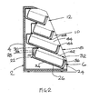
- a chiller or freezer cabinet 2 comprises an outer cabinet body 4 and a plurality of internal compartments 6, 8, 10, 12. Each compartment is sub-divided by an internal divider 14, 16, 18, 20.
- the compartment 6, 8, 10 and 12 are sized and arranged so as to be inclined rearwardly as shown in the Figures.
- the cabinet 2 comprises two relatively large compartments 6 and 8 which are of the same size and two relatively smaller, less deep, compartments 10, 12 which again are also of the same size.
- the rearward inclination of the compartments is achieved by suitable horizontal and vertical positioning of these compartments.
- the compartments are inclined downwardly from the horizontal by about 25°, as shown.
- Each compartment 6, 8, 10 or 12 is self-contained and comprises an outer, insulated tray-like support structure 22.
- the structure 22 comprises a front face 24, a base 26 and a rear wall 28.
- the tray 22 is suitably mounted to the body 4 of the cabinet 2, and a seal 30 is provided between adjacent compartments 6.
- an inner tray 32 for receiving produce.
- the inner tray 32 is spaced from the outer tray 22 to define a gap 34 therebetween.
- the front face 24 of the outer tray 22 and the front face 36 of the inner tray 30 are made from a transparent material such as glass which is preferably coated with an emission reducing coating to maintain the temperature within the compartment 6. This also allows produce to be seen more easily within the compartment 6.
- a refrigeration unit 38 Arranged between the rear of the inner tray 30 and the rear wall 28 of the outer structure 22 is a refrigeration unit 38 which comprises a fan and evaporator (not shown in detail). This creates a circulation 40 of cooled air around the gap 34 and forms an air curtain 42 across the open mouth 44 of each compartment 6. This opening 44 is defined between the upper edge 46 of the front wall 24 of the compartment 6 and the lower edge 46 of the front wall 24 of the immediately upwardly adjacent compartment 6. It will be seen that the air curtain 42 is generally horizontal.
- the described arrangement facilitates access to produce within the cabinet 2 and reduces power consumption due to the relatively short, horizontal, air curtains 42. Furthermore the temperature within each compartment can be more easily controlled as each compartment is essentially self contained.
- a cabinet 102 comprises two relatively large compartments 106 and 108 which are of the same size and two relatively smaller compartments 110, 112 which again are also of the same size.
- the rearward inclination of the compartments is achieved by suitable horizontal and vertical positioning of these compartments.
- the compartments 106, 108,110,112 are inclined upwardly from the horizontal by about 5°, as shown.
- Each compartment 106,108,110,112 is self-contained and comprises an outer, insulated tray-like support structure 122.
- the structure 122 comprises a front face 124, an insulated base 126 and an insulated rear wall 128.
- the structure 122 is suitably mounted to the body 104 of the cabinet 102.
- the tray structure 122 contains an inner tray 132 for receiving produce 133.
- the inner tray 132 is spaced from the outer tray 122 to define a gap 134 therebetween.
- the front face 124 of the outer tray 122 and the front face 136 of the inner tray 130 are made from a transparent material such as glass which is preferably coated with an emission reducing coating to maintain the temperature within the compartment 106.
- a refrigeration unit 138 Arranged between the rear of the inner tray 130 and the rear wall 128 of the outer structure 122 is a refrigeration unit 138 which comprises a fan and evaporator (not shown in detail). This creates a circulation 140 of cooled air around the gap 134 and forms an air curtain 142 across the open mouth 144 of each compartment 6.
- An air distribution duct 146 is formed in the upper part of each gap 134. For reasons of clarity it is only shown in the lowermost of the compartments 106.
- the end of the duct 146 is provided with a honeycomb member 148 which helps to create a non-turbulent airflow across the open mouth 144 of the compartment.
- the air curtain 42 is generally horizontal.
- Each compartment 106, 108, 110, 112 is provided with a drain 150 which receives melt water during defrosting operations.
- the drains 150 are connected to a common outlet pipe 152 which has an outlet 154 at the base of the cabinet 102 to allow melt water to be removed from the cabinet.
Landscapes
- Physics & Mathematics (AREA)
- Thermal Sciences (AREA)
- Freezers Or Refrigerated Showcases (AREA)
Abstract
Description
- The present invention relates to refrigerated display cabinets which can be used to hold chilled or frozen products. In particular the invention relates to "open" cabinets where a consumer can gain access to the display products without having to open a door on the cabinet.
- Open cabinets fall generally into two categories. The first of these uses one, or more usually more than one, vertical air curtains which extend over the front of the cabinet. The air curtains cover the entire front opening of the cabinet and a user must insert their hand through the air curtains to gain access to the products which are displayed on conventional shelves within the cabinet. The problem with such an arrangement is that it is quite difficult to maintain a long air curtain and also it is difficult within such displays to maintain a satisfactory vertical temperature radiant. The power consumption is also quite high due to the disruption t the air curtains caused by users continually disrupting the air curtains.
- Another cabinet type is the chest type cabinet which has an open top through which goods can be removed. There are, however, significant losses associated with radiation from the products within the cabinet. Also, the goods are not conveniently placed for the user.
- The present invention seeks to overcome or mitigate at least some of the above problems.
- From a first aspect, therefore, the invention provides an open faced refrigerated display cabinet comprising a plurality of product receiving compartments arranged one above the other, each compartment comprising an evaporator and fan system for producing a generally horizontal air curtain across the opening to the compartment.
- From a second broad aspect the invention also provides an open faced refrigerated display cabinet comprising a plurality of product receiving compartments arranged one above the other, and means for producing generally horizontal air curtains across the openings to the respective compartments.
- Thus, in accordance with the invention an elongate vertical air curtain extending across a number of shelves is replaced by a plurality of generally horizontal air curtains provided across the entrance to a plurality of vertically stacked compartments. In this way, the amount of ambient air penetrating the air curtain can be less and, as a result, the energy consumption of the unit will decrease. It will also be easier to reach the required food temperature. Also, each compartments can be manufactured separately and then assembled into and secured in the cabinet which acts to support the compartments in their desired positions.
- By "generally horizontal" is meant an angle of up to 30° to the horizontal, (either above or below) more preferably within 5-10° of the horizontal.
- In order to facilitate access to produce within the compartments, the compartments are preferably arranged such that the front face of the cabinet is inclined rearwardly from its bottom to its top.
- To facilitate this arrangement, the upper compartments of the cabinet are preferably less deep than the lower compartments.
- Preferably the front wall of each compartments inclines outwardly to facilitate the formation of the compartment opening. This can be effected by inclining the whole compartment or just the front wall.
- The entrance to each compartment is preferably formed between the top edge of the front wall of the compartment and the lower end of the front wall of the upwardly adjacent compartment.
- In order to improve the visibility of the products contained within the compartments, the front wall of each compartment is formed from a transparent material, for example glass.
- In order to reduce heat loss through the front of each compartment, the front face thereof preferably comprises a low emissivity layer. Such layers are widely used in other chiller/freezer applications and do not require further explanation here.
- The compartment is preferably double walled so as to define an air circulation passage around the produce carrying part of the compartment.
- The air circulation passage may comprise means to distribute the chilled air over the compartment opening in a controlled manner. For example, the air may pass through a honeycomb distributor adjacent the opening.
- Preferably each compartment is provided with a drain to receive melt water during defrost. Preferably the respective drains are taken to a common drain outlet at the bottom of the cabinet for disposal.
- A preferred embodiment of the invention will now be described by way of example only with reference to the Figures in which:
- Figure 1 shows a perspective view of an embodiment of the invention;
- Figure 2 shows a schematic cross-section through the embodiment of Figure 1; and
- Figure 3 shows a schematic section through a second embodiment of the invention.
-
- With reference to Figures 1 and 2, a chiller or
freezer cabinet 2 comprises anouter cabinet body 4 and a plurality ofinternal compartments internal divider compartment - With reference to Figure 2, the
cabinet 2 comprises two relativelylarge compartments 6 and 8 which are of the same size and two relatively smaller, less deep,compartments - Each
compartment like support structure 22. Thestructure 22 comprises afront face 24, abase 26 and arear wall 28. Thetray 22 is suitably mounted to thebody 4 of thecabinet 2, and aseal 30 is provided betweenadjacent compartments 6. - Within the
tray structure 22 is arranged aninner tray 32 for receiving produce. Theinner tray 32 is spaced from theouter tray 22 to define agap 34 therebetween. - The
front face 24 of theouter tray 22 and thefront face 36 of theinner tray 30 are made from a transparent material such as glass which is preferably coated with an emission reducing coating to maintain the temperature within thecompartment 6. This also allows produce to be seen more easily within thecompartment 6. - Arranged between the rear of the
inner tray 30 and therear wall 28 of theouter structure 22 is arefrigeration unit 38 which comprises a fan and evaporator (not shown in detail). This creates a circulation 40 of cooled air around thegap 34 and forms anair curtain 42 across theopen mouth 44 of eachcompartment 6. Thisopening 44 is defined between theupper edge 46 of thefront wall 24 of thecompartment 6 and thelower edge 46 of thefront wall 24 of the immediately upwardlyadjacent compartment 6. It will be seen that theair curtain 42 is generally horizontal. - The described arrangement facilitates access to produce within the
cabinet 2 and reduces power consumption due to the relatively short, horizontal,air curtains 42. Furthermore the temperature within each compartment can be more easily controlled as each compartment is essentially self contained. - A second embodiment of the invention is described with reference to Figure 3.
- This embodiment is generally similar to the first embodiment described above. Thus in this embodiment also, a
cabinet 102 comprises two relativelylarge compartments smaller compartments - The
compartments 106, 108,110,112 are inclined upwardly from the horizontal by about 5°, as shown. - Each compartment 106,108,110,112 is self-contained and comprises an outer, insulated tray-
like support structure 122. Thestructure 122 comprises afront face 124, aninsulated base 126 and an insulatedrear wall 128. Thestructure 122 is suitably mounted to thebody 104 of thecabinet 102. - As in the earlier embodiment the
tray structure 122 contains aninner tray 132 for receivingproduce 133. Theinner tray 132 is spaced from theouter tray 122 to define agap 134 therebetween. - The
front face 124 of theouter tray 122 and the front face 136 of the inner tray 130 are made from a transparent material such as glass which is preferably coated with an emission reducing coating to maintain the temperature within thecompartment 106. - Arranged between the rear of the inner tray 130 and the
rear wall 128 of theouter structure 122 is arefrigeration unit 138 which comprises a fan and evaporator (not shown in detail). This creates acirculation 140 of cooled air around thegap 134 and forms anair curtain 142 across the open mouth 144 of eachcompartment 6. - An
air distribution duct 146 is formed in the upper part of eachgap 134. For reasons of clarity it is only shown in the lowermost of thecompartments 106. The end of theduct 146 is provided with a honeycomb member 148 which helps to create a non-turbulent airflow across the open mouth 144 of the compartment. - As in the earlier embodiment, it will be seen that the
air curtain 42 is generally horizontal. - Each
compartment drain 150 which receives melt water during defrosting operations. Thedrains 150 are connected to acommon outlet pipe 152 which has anoutlet 154 at the base of thecabinet 102 to allow melt water to be removed from the cabinet. - It will be appreciated that the above description is of preferred embodiments of the invention only and should not be viewed in a limiting sense.
Claims (13)
- An open faced refrigerated display cabinet comprising a plurality of product receiving compartments arranged one above the other, each compartment comprising an evaporator and fan system for producing a generally horizontal air curtain across the opening to the compartment.
- A refrigerated display cabinet as claimed in claim 1 wherein the compartments are arranged such that the front face of the display cabinet is inclined rearwardly from its bottom to its top.
- A refrigerated display cabinet as claimed in claim 1 or 2 wherein the upper compartments of the cabinet are less deep than the lower compartments.
- A refrigerated display cabinet as claimed in any preceding claim wherein the front wall of a compartment is inclined outwardly.
- A refrigerated display cabinet as claimed in claim 4 wherein the whole compartment is inclined.
- A refrigerated display cabinet as claimed in any of claims 1 to 4 wherein compartment is generally horizontal and the front wall inclined thereto.
- A refrigerated display cabinet as claimed in any preceding claim wherein the opening to each compartment is formed between the top edge of the front wall of the compartment and the lower end of the front wall of the upwardly adjacent compartment.
- A refrigerated display cabinet as claimed in any preceding claim wherein the front wall of a compartment is formed from a transparent material, for example glass.
- A refrigerated display cabinet as claimed in claim 9 wherein the front wall is provided with a low emissivity layer.
- A refrigerated display cabinet as claimed in any preceding claim wherein an or each compartment is double walled so as to define an air circulation passage around the produce carrying part of the compartment.
- A refrigerated display cabinet as claimed in any preceding claim wherein each compartment is provided with a drain to receive melt water during defrost and wherein the respective drains are taken to a common drain outlet of the cabinet.
- A refrigerated display cabinet as claimed in any preceding claim wherein the air curtain issues through a flow distributor for producing a non-turbulent flow.
- An open faced refrigerated display cabinet comprising a plurality of product receiving compartments arranged one above the other, and means for producing generally horizontal air curtains across the openings to the respective compartments.
Priority Applications (1)
| Application Number | Priority Date | Filing Date | Title |
|---|---|---|---|
| EP03253665A EP1486148A1 (en) | 2003-06-10 | 2003-06-10 | Refrigerated display cabinets |
Applications Claiming Priority (1)
| Application Number | Priority Date | Filing Date | Title |
|---|---|---|---|
| EP03253665A EP1486148A1 (en) | 2003-06-10 | 2003-06-10 | Refrigerated display cabinets |
Publications (1)
| Publication Number | Publication Date |
|---|---|
| EP1486148A1 true EP1486148A1 (en) | 2004-12-15 |
Family
ID=33185973
Family Applications (1)
| Application Number | Title | Priority Date | Filing Date |
|---|---|---|---|
| EP03253665A Withdrawn EP1486148A1 (en) | 2003-06-10 | 2003-06-10 | Refrigerated display cabinets |
Country Status (1)
| Country | Link |
|---|---|
| EP (1) | EP1486148A1 (en) |
Cited By (3)
| Publication number | Priority date | Publication date | Assignee | Title |
|---|---|---|---|---|
| WO2008116476A1 (en) * | 2007-03-23 | 2008-10-02 | Carrier Corporation | Frigorific sales furniture |
| WO2008116475A1 (en) * | 2007-03-23 | 2008-10-02 | Carrier Corporation | Frigorific sales furniture |
| KR20230087010A (en) * | 2021-12-09 | 2023-06-16 | 대한민국(농촌진흥청장) | Freshness showcase for agricultural products |
Citations (4)
| Publication number | Priority date | Publication date | Assignee | Title |
|---|---|---|---|---|
| US2705875A (en) * | 1952-11-19 | 1955-04-12 | Gen Motors Corp | Multiple deck refrigerated display case |
| US3147602A (en) * | 1961-07-31 | 1964-09-08 | Dual Jet Refrigeration Company | Defrost method and means for refrigerated cabinets |
| US3196626A (en) * | 1962-10-24 | 1965-07-27 | Gabler Martin | Multi-tiered open bin refrigerated showcases and in method of refrigerating pertaining thereto |
| EP0089556A1 (en) * | 1982-03-22 | 1983-09-28 | Linde Aktiengesellschaft | Refrigerated display stand |
-
2003
- 2003-06-10 EP EP03253665A patent/EP1486148A1/en not_active Withdrawn
Patent Citations (4)
| Publication number | Priority date | Publication date | Assignee | Title |
|---|---|---|---|---|
| US2705875A (en) * | 1952-11-19 | 1955-04-12 | Gen Motors Corp | Multiple deck refrigerated display case |
| US3147602A (en) * | 1961-07-31 | 1964-09-08 | Dual Jet Refrigeration Company | Defrost method and means for refrigerated cabinets |
| US3196626A (en) * | 1962-10-24 | 1965-07-27 | Gabler Martin | Multi-tiered open bin refrigerated showcases and in method of refrigerating pertaining thereto |
| EP0089556A1 (en) * | 1982-03-22 | 1983-09-28 | Linde Aktiengesellschaft | Refrigerated display stand |
Cited By (4)
| Publication number | Priority date | Publication date | Assignee | Title |
|---|---|---|---|---|
| WO2008116476A1 (en) * | 2007-03-23 | 2008-10-02 | Carrier Corporation | Frigorific sales furniture |
| WO2008116475A1 (en) * | 2007-03-23 | 2008-10-02 | Carrier Corporation | Frigorific sales furniture |
| EP2139367B1 (en) | 2007-03-23 | 2017-09-13 | Carrier Corporation | Frigorific sales furniture |
| KR20230087010A (en) * | 2021-12-09 | 2023-06-16 | 대한민국(농촌진흥청장) | Freshness showcase for agricultural products |
Similar Documents
| Publication | Publication Date | Title |
|---|---|---|
| CN102843934B (en) | Refrigerated display units | |
| CN105358014B (en) | refrigerated display unit | |
| US20090013707A1 (en) | Air blanketed food preparation table | |
| US20160081493A1 (en) | Improvements in or relating to refrigerated display appliances | |
| US3021691A (en) | Air curtain reach-in display cooler | |
| JP2007187391A (en) | Refrigerated display case | |
| US4299099A (en) | Open front refrigeration system | |
| US20020047506A1 (en) | Refrigerator shelf | |
| EP1588650B1 (en) | Refrigerated vending machine | |
| US12290186B2 (en) | Refrigerated merchandising cabinet | |
| EP4015950B1 (en) | Refrigerated display cabinet for refrigerated products | |
| CN214855176U (en) | Q-shaped small material platform | |
| CN110762939B (en) | refrigerator | |
| US20220175154A1 (en) | Display refrigerators and freezers | |
| CN110762924B (en) | refrigerator | |
| CN110762918B (en) | Refrigerator with a refrigerator body | |
| CN110388778A (en) | Finned evaporator and refrigerator for refrigerator | |
| JP2632103B2 (en) | Cooling storage | |
| GB2367117A (en) | Refrigeration display cabinets | |
| EP2114214B1 (en) | Refrigerating cabinet | |
| KR200148070Y1 (en) | Cold air ventilation structure of open type show case | |
| JPH06288668A (en) | Open refrigeration show case system | |
| JPH043872A (en) | Refrigerator | |
| HK1103950A (en) | Refrigerated display merchandiser with improved air curtain | |
| HK1218846B (en) | Improvements in or relating to refrigerated display appliances |
Legal Events
| Date | Code | Title | Description |
|---|---|---|---|
| PUAI | Public reference made under article 153(3) epc to a published international application that has entered the european phase |
Free format text: ORIGINAL CODE: 0009012 |
|
| AK | Designated contracting states |
Kind code of ref document: A1 Designated state(s): AT BE BG CH CY CZ DE DK EE ES FI FR GB GR HU IE IT LI LU MC NL PT RO SE SI SK TR |
|
| AX | Request for extension of the european patent |
Extension state: AL LT LV MK |
|
| RIN1 | Information on inventor provided before grant (corrected) |
Inventor name: ZANNESE, DAVIDE Inventor name: DIJK, MATHIJS VAN |
|
| 17P | Request for examination filed |
Effective date: 20050615 |
|
| AKX | Designation fees paid |
Designated state(s): AT BE BG CH CY CZ DE DK EE ES FI FR GB GR HU IE IT LI LU MC NL PT RO SE SI SK TR |
|
| RAP1 | Party data changed (applicant data changed or rights of an application transferred) |
Owner name: CARRIER CORPORATION |
|
| GRAP | Despatch of communication of intention to grant a patent |
Free format text: ORIGINAL CODE: EPIDOSNIGR1 |
|
| STAA | Information on the status of an ep patent application or granted ep patent |
Free format text: STATUS: THE APPLICATION IS DEEMED TO BE WITHDRAWN |
|
| 18D | Application deemed to be withdrawn |
Effective date: 20100225 |