EP1485617B1 - Dynamic brake with backlash control for peristaltic pump - Google Patents
Dynamic brake with backlash control for peristaltic pump Download PDFInfo
- Publication number
- EP1485617B1 EP1485617B1 EP03743113A EP03743113A EP1485617B1 EP 1485617 B1 EP1485617 B1 EP 1485617B1 EP 03743113 A EP03743113 A EP 03743113A EP 03743113 A EP03743113 A EP 03743113A EP 1485617 B1 EP1485617 B1 EP 1485617B1
- Authority
- EP
- European Patent Office
- Prior art keywords
- roller pump
- pump
- predefined
- roller
- dynamic brake
- Prior art date
- Legal status (The legal status is an assumption and is not a legal conclusion. Google has not performed a legal analysis and makes no representation as to the accuracy of the status listed.)
- Expired - Lifetime
Links
- 230000002572 peristaltic effect Effects 0.000 title abstract description 13
- 239000012530 fluid Substances 0.000 claims abstract description 19
- 230000000977 initiatory effect Effects 0.000 claims abstract description 3
- 238000000034 method Methods 0.000 claims description 12
- 230000003213 activating effect Effects 0.000 claims description 5
- 238000004804 winding Methods 0.000 claims description 3
- 239000008280 blood Substances 0.000 description 4
- 210000004369 blood Anatomy 0.000 description 4
- 238000005086 pumping Methods 0.000 description 4
- 238000010586 diagram Methods 0.000 description 2
- 238000005070 sampling Methods 0.000 description 2
- 206010001526 Air embolism Diseases 0.000 description 1
- 230000004913 activation Effects 0.000 description 1
- 230000000712 assembly Effects 0.000 description 1
- 238000000429 assembly Methods 0.000 description 1
- 238000013130 cardiovascular surgery Methods 0.000 description 1
- 238000010276 construction Methods 0.000 description 1
- 230000001419 dependent effect Effects 0.000 description 1
- 210000005069 ears Anatomy 0.000 description 1
- 238000001990 intravenous administration Methods 0.000 description 1
- 210000003734 kidney Anatomy 0.000 description 1
- 239000000463 material Substances 0.000 description 1
- 238000012544 monitoring process Methods 0.000 description 1
- 230000035939 shock Effects 0.000 description 1
- 239000007787 solid Substances 0.000 description 1
Images



Classifications
-
- A—HUMAN NECESSITIES
- A61—MEDICAL OR VETERINARY SCIENCE; HYGIENE
- A61M—DEVICES FOR INTRODUCING MEDIA INTO, OR ONTO, THE BODY; DEVICES FOR TRANSDUCING BODY MEDIA OR FOR TAKING MEDIA FROM THE BODY; DEVICES FOR PRODUCING OR ENDING SLEEP OR STUPOR
- A61M1/00—Suction or pumping devices for medical purposes; Devices for carrying-off, for treatment of, or for carrying-over, body-liquids; Drainage systems
-
- A—HUMAN NECESSITIES
- A61—MEDICAL OR VETERINARY SCIENCE; HYGIENE
- A61M—DEVICES FOR INTRODUCING MEDIA INTO, OR ONTO, THE BODY; DEVICES FOR TRANSDUCING BODY MEDIA OR FOR TAKING MEDIA FROM THE BODY; DEVICES FOR PRODUCING OR ENDING SLEEP OR STUPOR
- A61M1/00—Suction or pumping devices for medical purposes; Devices for carrying-off, for treatment of, or for carrying-over, body-liquids; Drainage systems
- A61M1/14—Dialysis systems; Artificial kidneys; Blood oxygenators ; Reciprocating systems for treatment of body fluids, e.g. single needle systems for hemofiltration or pheresis
- A61M1/32—Oxygenators without membranes
-
- A—HUMAN NECESSITIES
- A61—MEDICAL OR VETERINARY SCIENCE; HYGIENE
- A61M—DEVICES FOR INTRODUCING MEDIA INTO, OR ONTO, THE BODY; DEVICES FOR TRANSDUCING BODY MEDIA OR FOR TAKING MEDIA FROM THE BODY; DEVICES FOR PRODUCING OR ENDING SLEEP OR STUPOR
- A61M1/00—Suction or pumping devices for medical purposes; Devices for carrying-off, for treatment of, or for carrying-over, body-liquids; Drainage systems
- A61M1/34—Filtering material out of the blood by passing it through a membrane, i.e. hemofiltration or diafiltration
-
- A—HUMAN NECESSITIES
- A61—MEDICAL OR VETERINARY SCIENCE; HYGIENE
- A61M—DEVICES FOR INTRODUCING MEDIA INTO, OR ONTO, THE BODY; DEVICES FOR TRANSDUCING BODY MEDIA OR FOR TAKING MEDIA FROM THE BODY; DEVICES FOR PRODUCING OR ENDING SLEEP OR STUPOR
- A61M1/00—Suction or pumping devices for medical purposes; Devices for carrying-off, for treatment of, or for carrying-over, body-liquids; Drainage systems
- A61M1/34—Filtering material out of the blood by passing it through a membrane, i.e. hemofiltration or diafiltration
- A61M1/3403—Regulation parameters
-
- A—HUMAN NECESSITIES
- A61—MEDICAL OR VETERINARY SCIENCE; HYGIENE
- A61M—DEVICES FOR INTRODUCING MEDIA INTO, OR ONTO, THE BODY; DEVICES FOR TRANSDUCING BODY MEDIA OR FOR TAKING MEDIA FROM THE BODY; DEVICES FOR PRODUCING OR ENDING SLEEP OR STUPOR
- A61M1/00—Suction or pumping devices for medical purposes; Devices for carrying-off, for treatment of, or for carrying-over, body-liquids; Drainage systems
- A61M1/36—Other treatment of blood in a by-pass of the natural circulatory system, e.g. temperature adaptation, irradiation ; Extra-corporeal blood circuits
- A61M1/3621—Extra-corporeal blood circuits
-
- A—HUMAN NECESSITIES
- A61—MEDICAL OR VETERINARY SCIENCE; HYGIENE
- A61M—DEVICES FOR INTRODUCING MEDIA INTO, OR ONTO, THE BODY; DEVICES FOR TRANSDUCING BODY MEDIA OR FOR TAKING MEDIA FROM THE BODY; DEVICES FOR PRODUCING OR ENDING SLEEP OR STUPOR
- A61M1/00—Suction or pumping devices for medical purposes; Devices for carrying-off, for treatment of, or for carrying-over, body-liquids; Drainage systems
- A61M1/36—Other treatment of blood in a by-pass of the natural circulatory system, e.g. temperature adaptation, irradiation ; Extra-corporeal blood circuits
- A61M1/3621—Extra-corporeal blood circuits
- A61M1/3666—Cardiac or cardiopulmonary bypass, e.g. heart-lung machines
-
- A—HUMAN NECESSITIES
- A61—MEDICAL OR VETERINARY SCIENCE; HYGIENE
- A61M—DEVICES FOR INTRODUCING MEDIA INTO, OR ONTO, THE BODY; DEVICES FOR TRANSDUCING BODY MEDIA OR FOR TAKING MEDIA FROM THE BODY; DEVICES FOR PRODUCING OR ENDING SLEEP OR STUPOR
- A61M1/00—Suction or pumping devices for medical purposes; Devices for carrying-off, for treatment of, or for carrying-over, body-liquids; Drainage systems
- A61M1/36—Other treatment of blood in a by-pass of the natural circulatory system, e.g. temperature adaptation, irradiation ; Extra-corporeal blood circuits
- A61M1/3621—Extra-corporeal blood circuits
- A61M1/367—Circuit parts not covered by the preceding subgroups of group A61M1/3621
-
- A—HUMAN NECESSITIES
- A61—MEDICAL OR VETERINARY SCIENCE; HYGIENE
- A61M—DEVICES FOR INTRODUCING MEDIA INTO, OR ONTO, THE BODY; DEVICES FOR TRANSDUCING BODY MEDIA OR FOR TAKING MEDIA FROM THE BODY; DEVICES FOR PRODUCING OR ENDING SLEEP OR STUPOR
- A61M60/00—Blood pumps; Devices for mechanical circulatory actuation; Balloon pumps for circulatory assistance
- A61M60/10—Location thereof with respect to the patient's body
- A61M60/104—Extracorporeal pumps, i.e. the blood being pumped outside the patient's body
- A61M60/109—Extracorporeal pumps, i.e. the blood being pumped outside the patient's body incorporated within extracorporeal blood circuits or systems
- A61M60/113—Extracorporeal pumps, i.e. the blood being pumped outside the patient's body incorporated within extracorporeal blood circuits or systems in other functional devices, e.g. dialysers or heart-lung machines
-
- A—HUMAN NECESSITIES
- A61—MEDICAL OR VETERINARY SCIENCE; HYGIENE
- A61M—DEVICES FOR INTRODUCING MEDIA INTO, OR ONTO, THE BODY; DEVICES FOR TRANSDUCING BODY MEDIA OR FOR TAKING MEDIA FROM THE BODY; DEVICES FOR PRODUCING OR ENDING SLEEP OR STUPOR
- A61M60/00—Blood pumps; Devices for mechanical circulatory actuation; Balloon pumps for circulatory assistance
- A61M60/20—Type thereof
- A61M60/247—Positive displacement blood pumps
- A61M60/253—Positive displacement blood pumps including a displacement member directly acting on the blood
- A61M60/268—Positive displacement blood pumps including a displacement member directly acting on the blood the displacement member being flexible, e.g. membranes, diaphragms or bladders
- A61M60/279—Peristaltic pumps, e.g. roller pumps
-
- A—HUMAN NECESSITIES
- A61—MEDICAL OR VETERINARY SCIENCE; HYGIENE
- A61M—DEVICES FOR INTRODUCING MEDIA INTO, OR ONTO, THE BODY; DEVICES FOR TRANSDUCING BODY MEDIA OR FOR TAKING MEDIA FROM THE BODY; DEVICES FOR PRODUCING OR ENDING SLEEP OR STUPOR
- A61M60/00—Blood pumps; Devices for mechanical circulatory actuation; Balloon pumps for circulatory assistance
- A61M60/40—Details relating to driving
- A61M60/424—Details relating to driving for positive displacement blood pumps
- A61M60/438—Details relating to driving for positive displacement blood pumps the force acting on the blood contacting member being mechanical
- A61M60/441—Details relating to driving for positive displacement blood pumps the force acting on the blood contacting member being mechanical generated by an electromotor
-
- A—HUMAN NECESSITIES
- A61—MEDICAL OR VETERINARY SCIENCE; HYGIENE
- A61M—DEVICES FOR INTRODUCING MEDIA INTO, OR ONTO, THE BODY; DEVICES FOR TRANSDUCING BODY MEDIA OR FOR TAKING MEDIA FROM THE BODY; DEVICES FOR PRODUCING OR ENDING SLEEP OR STUPOR
- A61M60/00—Blood pumps; Devices for mechanical circulatory actuation; Balloon pumps for circulatory assistance
- A61M60/50—Details relating to control
- A61M60/508—Electronic control means, e.g. for feedback regulation
-
- F—MECHANICAL ENGINEERING; LIGHTING; HEATING; WEAPONS; BLASTING
- F04—POSITIVE - DISPLACEMENT MACHINES FOR LIQUIDS; PUMPS FOR LIQUIDS OR ELASTIC FLUIDS
- F04B—POSITIVE-DISPLACEMENT MACHINES FOR LIQUIDS; PUMPS
- F04B43/00—Machines, pumps, or pumping installations having flexible working members
- F04B43/0009—Special features
- F04B43/0081—Special features systems, control, safety measures
-
- F—MECHANICAL ENGINEERING; LIGHTING; HEATING; WEAPONS; BLASTING
- F04—POSITIVE - DISPLACEMENT MACHINES FOR LIQUIDS; PUMPS FOR LIQUIDS OR ELASTIC FLUIDS
- F04B—POSITIVE-DISPLACEMENT MACHINES FOR LIQUIDS; PUMPS
- F04B43/00—Machines, pumps, or pumping installations having flexible working members
- F04B43/12—Machines, pumps, or pumping installations having flexible working members having peristaltic action
- F04B43/1253—Machines, pumps, or pumping installations having flexible working members having peristaltic action by using two or more rollers as squeezing elements, the rollers moving on an arc of a circle during squeezing
-
- F—MECHANICAL ENGINEERING; LIGHTING; HEATING; WEAPONS; BLASTING
- F04—POSITIVE - DISPLACEMENT MACHINES FOR LIQUIDS; PUMPS FOR LIQUIDS OR ELASTIC FLUIDS
- F04B—POSITIVE-DISPLACEMENT MACHINES FOR LIQUIDS; PUMPS
- F04B43/00—Machines, pumps, or pumping installations having flexible working members
- F04B43/12—Machines, pumps, or pumping installations having flexible working members having peristaltic action
- F04B43/1253—Machines, pumps, or pumping installations having flexible working members having peristaltic action by using two or more rollers as squeezing elements, the rollers moving on an arc of a circle during squeezing
- F04B43/1276—Means for pushing the rollers against the tubular flexible member
-
- F—MECHANICAL ENGINEERING; LIGHTING; HEATING; WEAPONS; BLASTING
- F04—POSITIVE - DISPLACEMENT MACHINES FOR LIQUIDS; PUMPS FOR LIQUIDS OR ELASTIC FLUIDS
- F04B—POSITIVE-DISPLACEMENT MACHINES FOR LIQUIDS; PUMPS
- F04B49/00—Control, e.g. of pump delivery, or pump pressure of, or safety measures for, machines, pumps, or pumping installations, not otherwise provided for, or of interest apart from, groups F04B1/00 - F04B47/00
- F04B49/06—Control using electricity
- F04B49/065—Control using electricity and making use of computers
-
- G—PHYSICS
- G16—INFORMATION AND COMMUNICATION TECHNOLOGY [ICT] SPECIALLY ADAPTED FOR SPECIFIC APPLICATION FIELDS
- G16H—HEALTHCARE INFORMATICS, i.e. INFORMATION AND COMMUNICATION TECHNOLOGY [ICT] SPECIALLY ADAPTED FOR THE HANDLING OR PROCESSING OF MEDICAL OR HEALTHCARE DATA
- G16H20/00—ICT specially adapted for therapies or health-improving plans, e.g. for handling prescriptions, for steering therapy or for monitoring patient compliance
- G16H20/10—ICT specially adapted for therapies or health-improving plans, e.g. for handling prescriptions, for steering therapy or for monitoring patient compliance relating to drugs or medications, e.g. for ensuring correct administration to patients
- G16H20/17—ICT specially adapted for therapies or health-improving plans, e.g. for handling prescriptions, for steering therapy or for monitoring patient compliance relating to drugs or medications, e.g. for ensuring correct administration to patients delivered via infusion or injection
-
- G—PHYSICS
- G16—INFORMATION AND COMMUNICATION TECHNOLOGY [ICT] SPECIALLY ADAPTED FOR SPECIFIC APPLICATION FIELDS
- G16H—HEALTHCARE INFORMATICS, i.e. INFORMATION AND COMMUNICATION TECHNOLOGY [ICT] SPECIALLY ADAPTED FOR THE HANDLING OR PROCESSING OF MEDICAL OR HEALTHCARE DATA
- G16H20/00—ICT specially adapted for therapies or health-improving plans, e.g. for handling prescriptions, for steering therapy or for monitoring patient compliance
- G16H20/40—ICT specially adapted for therapies or health-improving plans, e.g. for handling prescriptions, for steering therapy or for monitoring patient compliance relating to mechanical, radiation or invasive therapies, e.g. surgery, laser therapy, dialysis or acupuncture
-
- G—PHYSICS
- G16—INFORMATION AND COMMUNICATION TECHNOLOGY [ICT] SPECIALLY ADAPTED FOR SPECIFIC APPLICATION FIELDS
- G16H—HEALTHCARE INFORMATICS, i.e. INFORMATION AND COMMUNICATION TECHNOLOGY [ICT] SPECIALLY ADAPTED FOR THE HANDLING OR PROCESSING OF MEDICAL OR HEALTHCARE DATA
- G16H40/00—ICT specially adapted for the management or administration of healthcare resources or facilities; ICT specially adapted for the management or operation of medical equipment or devices
- G16H40/60—ICT specially adapted for the management or administration of healthcare resources or facilities; ICT specially adapted for the management or operation of medical equipment or devices for the operation of medical equipment or devices
- G16H40/63—ICT specially adapted for the management or administration of healthcare resources or facilities; ICT specially adapted for the management or operation of medical equipment or devices for the operation of medical equipment or devices for local operation
-
- G—PHYSICS
- G16—INFORMATION AND COMMUNICATION TECHNOLOGY [ICT] SPECIALLY ADAPTED FOR SPECIFIC APPLICATION FIELDS
- G16Z—INFORMATION AND COMMUNICATION TECHNOLOGY [ICT] SPECIALLY ADAPTED FOR SPECIFIC APPLICATION FIELDS, NOT OTHERWISE PROVIDED FOR
- G16Z99/00—Subject matter not provided for in other main groups of this subclass
-
- A—HUMAN NECESSITIES
- A61—MEDICAL OR VETERINARY SCIENCE; HYGIENE
- A61M—DEVICES FOR INTRODUCING MEDIA INTO, OR ONTO, THE BODY; DEVICES FOR TRANSDUCING BODY MEDIA OR FOR TAKING MEDIA FROM THE BODY; DEVICES FOR PRODUCING OR ENDING SLEEP OR STUPOR
- A61M2205/00—General characteristics of the apparatus
- A61M2205/10—General characteristics of the apparatus with powered movement mechanisms
- A61M2205/103—General characteristics of the apparatus with powered movement mechanisms rotating
-
- A—HUMAN NECESSITIES
- A61—MEDICAL OR VETERINARY SCIENCE; HYGIENE
- A61M—DEVICES FOR INTRODUCING MEDIA INTO, OR ONTO, THE BODY; DEVICES FOR TRANSDUCING BODY MEDIA OR FOR TAKING MEDIA FROM THE BODY; DEVICES FOR PRODUCING OR ENDING SLEEP OR STUPOR
- A61M2205/00—General characteristics of the apparatus
- A61M2205/33—Controlling, regulating or measuring
- A61M2205/3331—Pressure; Flow
- A61M2205/3334—Measuring or controlling the flow rate
-
- A—HUMAN NECESSITIES
- A61—MEDICAL OR VETERINARY SCIENCE; HYGIENE
- A61M—DEVICES FOR INTRODUCING MEDIA INTO, OR ONTO, THE BODY; DEVICES FOR TRANSDUCING BODY MEDIA OR FOR TAKING MEDIA FROM THE BODY; DEVICES FOR PRODUCING OR ENDING SLEEP OR STUPOR
- A61M2205/00—General characteristics of the apparatus
- A61M2205/33—Controlling, regulating or measuring
- A61M2205/3365—Rotational speed
-
- A—HUMAN NECESSITIES
- A61—MEDICAL OR VETERINARY SCIENCE; HYGIENE
- A61M—DEVICES FOR INTRODUCING MEDIA INTO, OR ONTO, THE BODY; DEVICES FOR TRANSDUCING BODY MEDIA OR FOR TAKING MEDIA FROM THE BODY; DEVICES FOR PRODUCING OR ENDING SLEEP OR STUPOR
- A61M2205/00—General characteristics of the apparatus
- A61M2205/35—Communication
-
- A—HUMAN NECESSITIES
- A61—MEDICAL OR VETERINARY SCIENCE; HYGIENE
- A61M—DEVICES FOR INTRODUCING MEDIA INTO, OR ONTO, THE BODY; DEVICES FOR TRANSDUCING BODY MEDIA OR FOR TAKING MEDIA FROM THE BODY; DEVICES FOR PRODUCING OR ENDING SLEEP OR STUPOR
- A61M2205/00—General characteristics of the apparatus
- A61M2205/50—General characteristics of the apparatus with microprocessors or computers
-
- A—HUMAN NECESSITIES
- A61—MEDICAL OR VETERINARY SCIENCE; HYGIENE
- A61M—DEVICES FOR INTRODUCING MEDIA INTO, OR ONTO, THE BODY; DEVICES FOR TRANSDUCING BODY MEDIA OR FOR TAKING MEDIA FROM THE BODY; DEVICES FOR PRODUCING OR ENDING SLEEP OR STUPOR
- A61M2205/00—General characteristics of the apparatus
- A61M2205/50—General characteristics of the apparatus with microprocessors or computers
- A61M2205/502—User interfaces, e.g. screens or keyboards
-
- A—HUMAN NECESSITIES
- A61—MEDICAL OR VETERINARY SCIENCE; HYGIENE
- A61M—DEVICES FOR INTRODUCING MEDIA INTO, OR ONTO, THE BODY; DEVICES FOR TRANSDUCING BODY MEDIA OR FOR TAKING MEDIA FROM THE BODY; DEVICES FOR PRODUCING OR ENDING SLEEP OR STUPOR
- A61M2205/00—General characteristics of the apparatus
- A61M2205/50—General characteristics of the apparatus with microprocessors or computers
- A61M2205/502—User interfaces, e.g. screens or keyboards
- A61M2205/505—Touch-screens; Virtual keyboard or keypads; Virtual buttons; Soft keys; Mouse touches
-
- F—MECHANICAL ENGINEERING; LIGHTING; HEATING; WEAPONS; BLASTING
- F04—POSITIVE - DISPLACEMENT MACHINES FOR LIQUIDS; PUMPS FOR LIQUIDS OR ELASTIC FLUIDS
- F04B—POSITIVE-DISPLACEMENT MACHINES FOR LIQUIDS; PUMPS
- F04B2205/00—Fluid parameters
- F04B2205/04—Pressure in the outlet chamber
-
- F—MECHANICAL ENGINEERING; LIGHTING; HEATING; WEAPONS; BLASTING
- F04—POSITIVE - DISPLACEMENT MACHINES FOR LIQUIDS; PUMPS FOR LIQUIDS OR ELASTIC FLUIDS
- F04B—POSITIVE-DISPLACEMENT MACHINES FOR LIQUIDS; PUMPS
- F04B2207/00—External parameters
- F04B2207/70—Warnings
Definitions
- the present invention is directed to a dynamic brake with backlash control, and more particularly, to a dynamic brake with backlash control for use with a peristaltic pump.
- Peristaltic pumps also referred to as roller pumps, are commonly utilized in medical applications. For instance, such pumps are often employed during cardiovascular surgery to facilitate circulation of blood between a patient and a heart-lung machine. Other common medical uses are the transfer of blood between a patient and a kidney dialyzer, and intravenous feeding of IV solutions. Generally, peristaltic pumps are simply structured, generate a constant flow, and employ disposable tubes as a member for fluid transfer.
- Peristaltic pumps are relatively simple in construction and typically include a housing having rollers which progressively compress a flexible tube at spaced intervals against an arcuate surface or raceway so as to flatten or locally reduce the cross-sectional area of the tube. In this manner, fluid leading to the flexible tube is continuously forced through the flexible tube by one or another of the rollers as it proceeds along the flexible tube over the arcuate surface or raceway.
- a conventional roller pump 10 as shown in FIG. 1, comprises a drive mechanism 14 furnished with a drive shaft 12, a rotating shaft 16 which rotates according to the rotation of drive shaft 12, and a hollow pump head 20 fixed to a housing 18 to which drive mechanism 14 is attached.
- This pump head 20 integrally incorporates a bearing block 24 through which rotating shaft 16 is inserted and rotatably supported by a pair of bearings 22 and a stator 26 arranged on the upper portion of bearing block 24.
- On the upper surface of stator 26 is formed a recess 28 through which the upper end of rotating shaft 16 is protruded. While this recess 28 is radially and outwardly spaced at a certain distance from the outer circumferential surface of rotating shaft 16, its inner circumferential surface 28a is coaxial with rotating shaft 16.
- a rotor assembly 30 is attached to the upper portion of rotating shaft 16 in such a way as to be placed inside recess 28 of stator 26 and to stay opposite the inner circumferential surface 28a thereof.
- This rotor 30 is fixed to rotating shaft 16 through a bolt 32, and is so constructed as to integrally rotate along with rotating shaft 16.
- a tube 36 which is filled with blood or other fluid material is placed between rotor 30 and stator 26. Tube 36 is clamped between respective rollers 34, which are attached to rotor 30, and inner circumferential surface 28a of stator 26, thereby maintaining tube 36 in a closed state at the point at which it is clamped.
- rotor 30 is rotated by the rotational motion of rotating shaft 16 driven by drive mechanism 14, and the clamped portions of tube 36 move according to the revolution of rollers 34 around rotating shaft 16. Therefore, fluid inside tube 36 is transferred according to the revolution of rollers 34.
- the rate of rotation of the rotating shaft 16 and hence the rollers 34 is normally adjustable so that the pumping rate of the fluid within tube 36 can be adjusted.
- the pumping rate can also be adjusted by adjusting the degree to which the rollers compress the flexible tube. This can be done in peristaltic pump assemblies by providing an adjustment mechanism for adjusting the distance between the axes of the rollers and hence the distance between the roller surface and the inner circumferential surface 28a of stator 26. Another important reason for peristaltic pumps to be adjustable in this fashion is that the compressibility, size, and other qualities of the flexible tube can vary considerably.
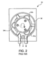
- roller pump 10 is rotating in a clockwise direction to force blood through the tube or fluid conduit 36.
- the roller pump 10 continues to rotate until the motor drive circuitry (not shown) is disabled. When this occurs, the roller pump coasts to a gradual stop. After the roller pump has come to a complete stop, it is desirable if the rollers 34a, 34b, 34c are left free to move (i.e., rotate). This is desirable because it allows the roller pump to be hand-operated (i.e., hand-cranked), if that should become necessary.
- the roller pump when the rollers are left free to move, it is common for the roller pump to experience some recoil, that is, some amount of counter rotation (e.g., 20 degrees of counter rotation) immediately after the rollers reach zero RPM.
- the counter rotation is depicted by the "broken line” arrow.
- the recoil referred to herein as backlash, is due to the fact that the rollers are left free to move, and because there is a certain amount of counter pressure in the fluid conduit which opposes the normal rotation (e.g., clockwise rotation) of the roller pump. Backlash may cause air to be introduced into the conduit. This highly undesirable condition may lead to an air embolism or even death of the patient.
- a roller pump comprising a rotor, a tube supporting bracket having a pair of pumping shoes, and fluid compressible tubes mounted between the rotor and the pumping shoes.
- said tubes before being mounted in the tube support bracket have ears to pretension them and to set the pick up or delivery accuracy to compensate for manufacturers tolerances in the inside and outside diameters of the tubes.
- a continuously applied brake is an electrical or mechanical brake which is continuously applied to stop the motor within the pump. The brake is never removed until it is deemed necessary for the pump to begin moving the rollers again, so as to move fluid in the pump.
- These pumps may activate the continuously applied brake as soon as the motor drive circuitry receives a signal to stop the pump. While the continuously applied brake does, to some extent, prevent backlash, it also prevents the rollers from freely moving after the rollers have stopped rotating. In this instance, the continuously applied brake would preclude the option of hand operating the roller pump.
- a roller pump that includes means for activating a dynamic brake when the roller pump decelerates below a predefined pump speed.
- the pump also includes means for deactivating the dynamic brake when pressure in the fluid conduit of the roller pump subsides.
- the aforementioned and other objects are achieved by a method for preventing backlash in a roller pump.
- the method involves determining whether the speed of the roller pump is less than a predefined roller pump speed threshold. When it has been determined that the speed of the roller pump is less than the predefined roller pump speed threshold, a dynamic brake is activated. Then, after a predefined period of time has elapsed, the dynamic brake is deactivated.
- FIG. 1 is a cross-sectional view of a peristaltic pump as known in the prior art
- FIG. 2 is a top plan view of a peristaltic pump as known in the art
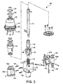
- FIG. 3 is an exploded view of a peristaltic pump according to the present invention.
- FIG. 4 is a block diagram of a preferred embodiment of the dynamic brake and backlash control system of the present invention.
- FIG. 5 is a flow chart of an exemplary process through which software may control dynamic braking.
- Rotor assembly 100 includes a pump or rotor hub 102, at least one and preferably two opposing roller slides 104a, 104b, a roller 106a, 106b disposed within each roller slide, respectively, and an adjustment knob 108 for adjusting the occlusion of the flexible tube within the pump housing.
- the rotor assembly 100 is rotatably supported within a stator similar to that shown in FIG. 1 and as known in the art, and the inner circumferential surface of the stator forms the raceway for the rollers 106a, 106b of the present invention.
- a main shaft 110 extending through the rotor assembly 100 rotates according to the rotation of a drive shaft, which is rotated by a conventional drive mechanism, as shown in FIG. 1, for example.
- Each of the roller slides 104a, 104b includes a plurality of recesses or channels 118 for receiving an extension spring 120.
- Each of the channels 118 includes, preferably at an outer end thereof, a peg to which the opposing ends of the springs are attached.
- the opposing roller slides 104a and 104b are interconnected by a plurality of springs 120.
- the rollers 106a, 106b are firmly held in the proper position within the roller slides 104a, 104b, respectively, by a roller shaft 124.
- Various bearings 126 and washers 128 may also be used for mounting the rollers 106a, 106b within the roller slides 104a, 104b, respectively.
- the rotor assembly 100 further includes a cam block 138 which is spring loaded by a spring 142.
- a guide collar 144 engages an upper surface of the cam block 138 and vertically adjusts the position of cam block 138 through rotation of the adjustment knob 108 and a screw adjustment member 146 which rotates therewith and thereby correspondingly rotates the guide collar 144.
- the cam block 138 includes opposing wedge-shaped projections 148 which engage a corresponding wedge-shaped surface (not shown) on an inner surface of each roller slide 104a, 104b.
- cam block 138 is also moved downward such that the wedge projections 148 on the cam block 138 force the roller slides 104a, 104b radially outward against the force of extension springs 120.
- the adjustment knob 108 also includes an occlusion indicator ring 150 and a detent ring 152 for providing an audible indication of the degree of rotation of the knob 108.
- the detent ring 152 preferably has a scalloped periphery defining a plurality of teeth 153 with generally U-shaped cut-outs 155 therebetween.
- a plurality of retaining rings 154 and bearings 156 may also be provided.
- the present invention employs an intelligent, momentarily applied dynamic brake, rather than a continuously applied brake.
- This momentary dynamic brake avoids backlash, due to counter rotation, and in addition, it does not preclude the option of hand operating the roller pump.
- the dynamic brake achieves this by initiating the braking operation after the pump is requested to stop, and only after the roller pump has decelerated below a predefined speed (e.g., 20 rpm).
- a predefined speed e.g. 20 rpm
- the dynamic brake provides braking for only a very brief duration. It is advantageous to initiate braking after the pump has decelerated below this predefined speed because it prevents abrupt deceleration and mechanical shock to the system.
- FIG. 4 is a block diagram of the dynamic brake and backlash control system 200, in accordance with a preferred embodiment of the present invention.
- the system involves software 205, a motor 210 (e.g., a 3-phase brushless motor, though it will be understood that the dynamic braking operation of the present invention is also applicable to brush motors), where the motor 210 drives the pump's rollers, a motor controller 215 and a tachometer 220.
- the software 205 which controls the dynamic braking process, is stored in a memory which is preferably located in the roller pump. In general, the software 205 controls the momentary dynamic braking process by monitoring the speed of the roller pump based on the output of the tachometer 220.
- the software 205 determines that it is appropriate to employ the momentary dynamic brake, for example, when the software 205 determines that the pump has been requested to stop and that the speed of the roller pump has dropped below a predetermined pump speed threshold, the software 205 issues a first instruction 225 for the motor controller 215 to activate a control signal 230, where the activation of the control signal 230 activates the dynamic brake.
- the control signal 230 may activate the dynamic brake by simultaneously turning on all three phases of the 3-phase motor. This effectively results in shorting the motor windings, which in turn, provides a braking torque that is dependent on motor speed.
- the software 205 only permits dynamic braking for a relatively short, predetermined time period, which is only long enough for the fluid pressure in the fluid conduit to subside. After this relatively short time duration expires, the software 205 issues a second instruction 235 for the motor controller 215 to deactivate the control signal 230 which releases the dynamic brake. Upon releasing the dynamic brake, the rollers can rotate freely and the roller pump may be hand-operated. In the event of a fault condition, where the dynamic brake is not released, it is still possible to hand-operate the pump.
- FIG. 5 is a flow chart depicting an exemplary process 300 through which the software 205 may control momentary dynamic braking.
- the software 205 begins the process upon receiving an indication that the pump shall be stopped. When this occurs, the software 205, as shown in step 305, begins sampling the speed of the roller pump (e.g., by sampling the output of the tachometer 220). The software 205 then compares the sampled pump speed to a predefined pump speed threshold (e.g., 20 rpm) according to step 307. If, based on this comparison, the software 205 determines that the sampled pump speed has not dropped below this threshold, in accordance with the "NO" path out of decision step 310, the software 205 returns to step 305 and takes another pump speed sample.
- a predefined pump speed threshold e.g. 20 rpm
- the software 205 continues to sample the pump speed and compare it to the predefined threshold until it has determined that the pump speed drops below the threshold, in accordance with the "YES" path out of decision step 310.
- the software 205 instructs the motor controller 215 to engage the dynamic brake. Again, if the motor is a 3-phase motor, this may involve activating all three phases of the 3-phase motor 210, as indicated by step 312.
- the software 205 begins decrementing a timer in accordance with step 315.
- the software 205 determines whether the timer has decremented to zero, as shown by decision step 317. If, according to the "NO" path out of decision step 320, the timer has not yet decremented to zero, the software 205 once again decrements the timer according to step 315. The software 205 continues to decrement the timer and, after doing so, determine whether the timer has reached zero.
- the software 205 instructs the motor controller 215 to send the appropriate signal to the motor releasing the dynamic brake, as shown by step 320.
- the period of time associated with the timer should be sufficiently long to allow the fluid pressure in the conduit to subside. In a preferred embodiment of the present invention, this may be approximately 2 seconds, plus or minus 1 second.
Landscapes
- Health & Medical Sciences (AREA)
- Engineering & Computer Science (AREA)
- Heart & Thoracic Surgery (AREA)
- Public Health (AREA)
- General Health & Medical Sciences (AREA)
- Biomedical Technology (AREA)
- Veterinary Medicine (AREA)
- Anesthesiology (AREA)
- Hematology (AREA)
- Life Sciences & Earth Sciences (AREA)
- Animal Behavior & Ethology (AREA)
- Vascular Medicine (AREA)
- Cardiology (AREA)
- Mechanical Engineering (AREA)
- General Engineering & Computer Science (AREA)
- Epidemiology (AREA)
- Medical Informatics (AREA)
- Primary Health Care (AREA)
- Pulmonology (AREA)
- Emergency Medicine (AREA)
- Urology & Nephrology (AREA)
- Bioinformatics & Cheminformatics (AREA)
- Nuclear Medicine, Radiotherapy & Molecular Imaging (AREA)
- Chemical & Material Sciences (AREA)
- Business, Economics & Management (AREA)
- Medicinal Chemistry (AREA)
- Computer Hardware Design (AREA)
- Surgery (AREA)
- General Business, Economics & Management (AREA)
- External Artificial Organs (AREA)
- Reciprocating Pumps (AREA)
- Control Of Positive-Displacement Pumps (AREA)
- Stopping Of Electric Motors (AREA)
- Regulating Braking Force (AREA)
- Braking Arrangements (AREA)
- Infusion, Injection, And Reservoir Apparatuses (AREA)
- Media Introduction/Drainage Providing Device (AREA)
Abstract
Description
- The present invention is directed to a dynamic brake with backlash control, and more particularly, to a dynamic brake with backlash control for use with a peristaltic pump.
- Peristaltic pumps, also referred to as roller pumps, are commonly utilized in medical applications. For instance, such pumps are often employed during cardiovascular surgery to facilitate circulation of blood between a patient and a heart-lung machine. Other common medical uses are the transfer of blood between a patient and a kidney dialyzer, and intravenous feeding of IV solutions. Generally, peristaltic pumps are simply structured, generate a constant flow, and employ disposable tubes as a member for fluid transfer.
- Peristaltic pumps are relatively simple in construction and typically include a housing having rollers which progressively compress a flexible tube at spaced intervals against an arcuate surface or raceway so as to flatten or locally reduce the cross-sectional area of the tube. In this manner, fluid leading to the flexible tube is continuously forced through the flexible tube by one or another of the rollers as it proceeds along the flexible tube over the arcuate surface or raceway.
- A
conventional roller pump 10, as shown in FIG. 1, comprises adrive mechanism 14 furnished with adrive shaft 12, a rotatingshaft 16 which rotates according to the rotation ofdrive shaft 12, and ahollow pump head 20 fixed to ahousing 18 to whichdrive mechanism 14 is attached. Thispump head 20 integrally incorporates abearing block 24 through which rotatingshaft 16 is inserted and rotatably supported by a pair ofbearings 22 and astator 26 arranged on the upper portion ofbearing block 24. On the upper surface ofstator 26 is formed arecess 28 through which the upper end of rotatingshaft 16 is protruded. While thisrecess 28 is radially and outwardly spaced at a certain distance from the outer circumferential surface of rotatingshaft 16, its inner circumferential surface 28a is coaxial with rotatingshaft 16. - A
rotor assembly 30 is attached to the upper portion of rotatingshaft 16 in such a way as to be placed insiderecess 28 ofstator 26 and to stay opposite the inner circumferential surface 28a thereof. Thisrotor 30 is fixed to rotatingshaft 16 through abolt 32, and is so constructed as to integrally rotate along with rotatingshaft 16. On the outer circumferential surface ofrotor 30, at least oneroller 34 is arranged so as to rotate about its own axes. Atube 36 which is filled with blood or other fluid material is placed betweenrotor 30 andstator 26.Tube 36 is clamped betweenrespective rollers 34, which are attached torotor 30, and inner circumferential surface 28a ofstator 26, thereby maintainingtube 36 in a closed state at the point at which it is clamped. - Thus, in a
conventional roller pump 10,rotor 30 is rotated by the rotational motion of rotatingshaft 16 driven bydrive mechanism 14, and the clamped portions oftube 36 move according to the revolution ofrollers 34 around rotatingshaft 16. Therefore, fluid insidetube 36 is transferred according to the revolution ofrollers 34. The rate of rotation of the rotatingshaft 16 and hence therollers 34 is normally adjustable so that the pumping rate of the fluid withintube 36 can be adjusted. However, the pumping rate can also be adjusted by adjusting the degree to which the rollers compress the flexible tube. This can be done in peristaltic pump assemblies by providing an adjustment mechanism for adjusting the distance between the axes of the rollers and hence the distance between the roller surface and the inner circumferential surface 28a ofstator 26. Another important reason for peristaltic pumps to be adjustable in this fashion is that the compressibility, size, and other qualities of the flexible tube can vary considerably. - Referring also to FIG. 2, the operation of a
typical roller pump 10 is illustrated. Although roller pumps are typically capable of rotating in either direction, the solid arrow in FIG. 2 indicates thatroller pump 10 is rotating in a clockwise direction to force blood through the tube orfluid conduit 36.
Generally, theroller pump 10 continues to rotate until the motor drive circuitry (not shown) is disabled. When this occurs, the roller pump coasts to a gradual stop. After the roller pump has come to a complete stop, it is desirable if therollers - However, when the rollers are left free to move, it is common for the roller pump to experience some recoil, that is, some amount of counter rotation (e.g., 20 degrees of counter rotation) immediately after the rollers reach zero RPM. In FIG. 2, the counter rotation is depicted by the "broken line" arrow. The recoil, referred to herein as backlash, is due to the fact that the rollers are left free to move, and because there is a certain amount of counter pressure in the fluid conduit which opposes the normal rotation (e.g., clockwise rotation) of the roller pump. Backlash may cause air to be introduced into the conduit. This highly undesirable condition may lead to an air embolism or even death of the patient.
In order to avoid such a backlash, the document US 3,737,251 discloses a roller pump comprising a rotor, a tube supporting bracket having a pair of pumping shoes, and fluid compressible tubes mounted between the rotor and the pumping shoes. For that purpose, said tubes, before being mounted in the tube support bracket have ears to pretension them and to set the pick up or delivery accuracy to compensate for manufacturers tolerances in the inside and outside diameters of the tubes. - Some roller pumps employ a continuously applied brake to prevent backlash due to counter rotation. A continuously applied brake is an electrical or mechanical brake which is continuously applied to stop the motor within the pump. The brake is never removed until it is deemed necessary for the pump to begin moving the rollers again, so as to move fluid in the pump. These pumps may activate the continuously applied brake as soon as the motor drive circuitry receives a signal to stop the pump. While the continuously applied brake does, to some extent, prevent backlash, it also prevents the rollers from freely moving after the rollers have stopped rotating. In this instance, the continuously applied brake would preclude the option of hand operating the roller pump.
- Accordingly, there is a need in the art for an improved braking feature for a roller pump, which substantially reduces the occurrence of backlash yet allows the roller pump to be hand operated if necessary.
- It is an object of the present invention to provide an intelligent, momentary dynamic brake for use in a roller pump to prevent backlash.
- It is also an object of the present invention to provide intelligent, momentary dynamic braking in a roller pump without jeopardizing the ability to hand operate the pump after the rollers have stopped rotating.
- In a first embodiment of the present invention, the aforementioned and other objects are achieved by a roller pump that includes means for activating a dynamic brake when the roller pump decelerates below a predefined pump speed. The pump also includes means for deactivating the dynamic brake when pressure in the fluid conduit of the roller pump subsides.
- In another embodiment of the present invention, the aforementioned and other objects are achieved by a method for preventing backlash in a roller pump. The method involves determining whether the speed of the roller pump is less than a predefined roller pump speed threshold. When it has been determined that the speed of the roller pump is less than the predefined roller pump speed threshold, a dynamic brake is activated. Then, after a predefined period of time has elapsed, the dynamic brake is deactivated.
- These, and other, objects, features and advantages of the present invention will become more readily apparent to those skilled in the art upon reading the following detailed description, in conjunction with the appended drawings, in which:
- FIG. 1 is a cross-sectional view of a peristaltic pump as known in the prior art;
- FIG. 2 is a top plan view of a peristaltic pump as known in the art;
- FIG. 3 is an exploded view of a peristaltic pump according to the present invention;
- FIG. 4 is a block diagram of a preferred embodiment of the dynamic brake and backlash control system of the present invention; and
- FIG. 5 is a flow chart of an exemplary process through which software may control dynamic braking.
- A peristaltic pump rotor assembly according to the present invention is shown generally by
reference numeral 100 in the exploded view of FIG. 3.Rotor assembly 100 includes a pump orrotor hub 102, at least one and preferably twoopposing roller slides roller adjustment knob 108 for adjusting the occlusion of the flexible tube within the pump housing. Therotor assembly 100 is rotatably supported within a stator similar to that shown in FIG. 1 and as known in the art, and the inner circumferential surface of the stator forms the raceway for therollers main shaft 110 extending through therotor assembly 100 rotates according to the rotation of a drive shaft, which is rotated by a conventional drive mechanism, as shown in FIG. 1, for example. - Each of the
roller slides channels 118 for receiving anextension spring 120. Each of thechannels 118 includes, preferably at an outer end thereof, a peg to which the opposing ends of the springs are attached. As such, the opposing roller slides 104a and 104b are interconnected by a plurality ofsprings 120. Therollers roller shaft 124.Various bearings 126 andwashers 128 may also be used for mounting therollers - As shown in the illustrated embodiment, the
rotor assembly 100 further includes acam block 138 which is spring loaded by aspring 142. Aguide collar 144 engages an upper surface of thecam block 138 and vertically adjusts the position ofcam block 138 through rotation of theadjustment knob 108 and ascrew adjustment member 146 which rotates therewith and thereby correspondingly rotates theguide collar 144. Thecam block 138 includes opposing wedge-shapedprojections 148 which engage a corresponding wedge-shaped surface (not shown) on an inner surface of eachroller slide adjustment knob 108 is rotated clockwise, for example, and screwadjustment member 146 correspondingly rotates so as to moveguide collar 144 in a downward direction,cam block 138 is also moved downward such that thewedge projections 148 on thecam block 138 force the roller slides 104a, 104b radially outward against the force of extension springs 120. - The
adjustment knob 108 also includes anocclusion indicator ring 150 and adetent ring 152 for providing an audible indication of the degree of rotation of theknob 108. As shown, thedetent ring 152 preferably has a scalloped periphery defining a plurality ofteeth 153 with generally U-shaped cut-outs 155 therebetween. A plurality of retainingrings 154 andbearings 156 may also be provided. - Whereas the prior art included a continuously applied brake to prevent backlash of the
rollers - FIG. 4 is a block diagram of the dynamic brake and
backlash control system 200, in accordance with a preferred embodiment of the present invention. As shown, the system involvessoftware 205, a motor 210 (e.g., a 3-phase brushless motor, though it will be understood that the dynamic braking operation of the present invention is also applicable to brush motors), where themotor 210 drives the pump's rollers, amotor controller 215 and atachometer 220. Thesoftware 205, which controls the dynamic braking process, is stored in a memory which is preferably located in the roller pump. In general, thesoftware 205 controls the momentary dynamic braking process by monitoring the speed of the roller pump based on the output of thetachometer 220. When thesoftware 205 determines that it is appropriate to employ the momentary dynamic brake, for example, when thesoftware 205 determines that the pump has been requested to stop and that the speed of the roller pump has dropped below a predetermined pump speed threshold, thesoftware 205 issues afirst instruction 225 for themotor controller 215 to activate acontrol signal 230, where the activation of thecontrol signal 230 activates the dynamic brake. If the motor is a 3-phase motor, thecontrol signal 230 may activate the dynamic brake by simultaneously turning on all three phases of the 3-phase motor. This effectively results in shorting the motor windings, which in turn, provides a braking torque that is dependent on motor speed. However, thesoftware 205 only permits dynamic braking for a relatively short, predetermined time period, which is only long enough for the fluid pressure in the fluid conduit to subside. After this relatively short time duration expires, thesoftware 205 issues asecond instruction 235 for themotor controller 215 to deactivate thecontrol signal 230 which releases the dynamic brake. Upon releasing the dynamic brake, the rollers can rotate freely and the roller pump may be hand-operated. In the event of a fault condition, where the dynamic brake is not released, it is still possible to hand-operate the pump. - FIG. 5 is a flow chart depicting an
exemplary process 300 through which thesoftware 205 may control momentary dynamic braking. Thesoftware 205 begins the process upon receiving an indication that the pump shall be stopped. When this occurs, thesoftware 205, as shown instep 305, begins sampling the speed of the roller pump (e.g., by sampling the output of the tachometer 220).
Thesoftware 205 then compares the sampled pump speed to a predefined pump speed threshold (e.g., 20 rpm) according tostep 307. If, based on this comparison, thesoftware 205 determines that the sampled pump speed has not dropped below this threshold, in accordance with the "NO" path out ofdecision step 310, thesoftware 205 returns to step 305 and takes another pump speed sample. - The
software 205 continues to sample the pump speed and compare it to the predefined threshold until it has determined that the pump speed drops below the threshold, in accordance with the "YES" path out ofdecision step 310. When thesoftware 205 has made this determination, it instructs themotor controller 215 to engage the dynamic brake. Again, if the motor is a 3-phase motor, this may involve activating all three phases of the 3-phase motor 210, as indicated bystep 312. - When the
motor controller 215 engages the dynamic brake, thesoftware 205 begins decrementing a timer in accordance withstep 315. Thesoftware 205 then determines whether the timer has decremented to zero, as shown bydecision step 317. If, according to the "NO" path out ofdecision step 320, the timer has not yet decremented to zero, thesoftware 205 once again decrements the timer according tostep 315. Thesoftware 205 continues to decrement the timer and, after doing so, determine whether the timer has reached zero. When it does determine that the timer has decremented to zero, in accordance with the "YES" path out ofdecision step 317, thesoftware 205 instructs themotor controller 215 to send the appropriate signal to the motor releasing the dynamic brake, as shown bystep 320. The period of time associated with the timer should be sufficiently long to allow the fluid pressure in the conduit to subside. In a preferred embodiment of the present invention, this may be approximately 2 seconds, plus or minus 1 second. - While the above described dynamic brake has been illustrated with respect to a preferred embodiment and use within a peristaltic pump, it should be apparent to one skilled in the art that the applications of the momentary dynamic brake extend further to other devices and situations within the scope of the present invention.
Claims (10)
- A roller pump (100) comprising:a fluid conduit; characterised in that it further comprises:means (205, 215) for activating a dynamic brake when the roller pump (100) decelerates below a predefined pump speed; andmeans (205, 215) for deactivating the dynamic brake when pressure in the fluid conduit subsides.
- The roller pump (100) of claim 1 further comprising:means (205, 220) for determining when the roller pump decelerates below the predefined pump speed.
- The roller pump (100) of claim 2, wherein said means for determining when the roller pump decelerates below the predefined pump speed comprises:a tachometer (220) for measuring roller pump speed; andmeans (205) for comparing measured roller pump speed to the predefined pump speed.
- The roller pump (100) of claim 1 further comprising:a motor (210); andcontrol means (205, 215) for shorting the windings in the motor.
- The roller pump (100) of claim 1 further comprising an electric motor (210), wherein said means for deactivating the dynamic brake when pressure in the fluid conduit subsides comprises:means (205) for determining whether a predefined period of time has elapsed; andmeans (205, 215) for deactivating all phases of the electric motor (210) when the time period has elapsed, wherein the predefined period of time represents a period of time required for the pressure in the fluid conduit to subside.
- A method for preventing backlash of a roller pump, characterised in that it comprises the steps of:during deceleration of the roller pump, determining whether the speed of the roller pump is less than a predefined roller pump speed threshold;when it has been determined that the speed of the roller pump is less than the predefined roller pump speed threshold, activating a dynamic brake; anddeactivating the dynamic brake after a predefined period of time has elapsed.
- The method of claim 6, wherein said step of determining whether the speed of the roller pump is less than a predefined roller pump speed threshold comprises the steps of:measuring roller pump speed; andcomparing measured roller pump speed to the predefined roller pump speed threshold.
- The method of claim 6, wherein said step of activating a dynamic brake comprises the step of:shorting the windings of a motor in the roller pump.
- The method of claim 6, wherein said step of deactivating the dynamic brake after a predefined period of time has elapsed comprises the step of:deactivating all phases of an electric motor in the roller pump.
- The method of claim 6 further comprising the steps of:initiating a timer which reflects an amount of time equal to the predefined period of time; anddecrementing the timer until it indicates that the predefined period of time has elapsed, wherein the predefined period of time represents a period of time required for pressure in a fluid conduit associated with the roller pump to subside.
Applications Claiming Priority (3)
| Application Number | Priority Date | Filing Date | Title |
|---|---|---|---|
| US10/078,679 US6609900B2 (en) | 1996-09-30 | 2002-02-21 | Dynamic brake with backlash control for peristaltic pump |
| US78679 | 2002-02-21 | ||
| PCT/US2003/003411 WO2003072944A1 (en) | 2002-02-21 | 2003-02-04 | Dynamic brake with backlash control for peristaltic pump |
Publications (3)
| Publication Number | Publication Date |
|---|---|
| EP1485617A1 EP1485617A1 (en) | 2004-12-15 |
| EP1485617A4 EP1485617A4 (en) | 2006-03-08 |
| EP1485617B1 true EP1485617B1 (en) | 2006-12-27 |
Family
ID=27765217
Family Applications (1)
| Application Number | Title | Priority Date | Filing Date |
|---|---|---|---|
| EP03743113A Expired - Lifetime EP1485617B1 (en) | 2002-02-21 | 2003-02-04 | Dynamic brake with backlash control for peristaltic pump |
Country Status (7)
| Country | Link |
|---|---|
| US (1) | US6609900B2 (en) |
| EP (1) | EP1485617B1 (en) |
| JP (1) | JP4422489B2 (en) |
| AT (1) | ATE349616T1 (en) |
| AU (1) | AU2003225547A1 (en) |
| DE (1) | DE60310693T2 (en) |
| WO (1) | WO2003072944A1 (en) |
Families Citing this family (17)
| Publication number | Priority date | Publication date | Assignee | Title |
|---|---|---|---|---|
| WO2004103649A1 (en) * | 2003-05-20 | 2004-12-02 | Fujitsu Limited | Method for controlling backlash compensation, backlash compensation controller and program for controlling backlash compensation |
| US7297166B2 (en) | 2003-06-25 | 2007-11-20 | Depuy Products, Inc. | Assembly tool for modular implants and associated method |
| US8998919B2 (en) | 2003-06-25 | 2015-04-07 | DePuy Synthes Products, LLC | Assembly tool for modular implants, kit and associated method |
| US7582092B2 (en) | 2003-06-25 | 2009-09-01 | Depuy Products, Inc. | Assembly tool for modular implants and associated method |
| US8556912B2 (en) | 2007-10-30 | 2013-10-15 | DePuy Synthes Products, LLC | Taper disengagement tool |
| US8518050B2 (en) | 2007-10-31 | 2013-08-27 | DePuy Synthes Products, LLC | Modular taper assembly device |
| JP5351752B2 (en) * | 2009-12-28 | 2013-11-27 | 株式会社マキタ | Electric tool |
| US8533921B2 (en) | 2010-06-15 | 2013-09-17 | DePuy Synthes Products, LLC | Spiral assembly tool |
| US9095452B2 (en) | 2010-09-01 | 2015-08-04 | DePuy Synthes Products, Inc. | Disassembly tool |
| CN103813764B (en) | 2011-04-06 | 2017-04-19 | 德普伊新特斯产品有限责任公司 | Instrument components for implantation of revision hip prosthesis and orthopedic procedures using it |
| CN105829717B (en) * | 2013-10-09 | 2018-05-18 | 株式会社威尔科 | Pump |
| US10578094B2 (en) * | 2016-05-04 | 2020-03-03 | Curium Us Llc | Pump for operation in radioactive environment |
| SE540068C2 (en) * | 2016-06-07 | 2018-03-13 | Haurir Medical Ab | Body drainage apparatus with rotatable peristaltic pump |
| US10690127B2 (en) * | 2016-08-30 | 2020-06-23 | Alcon Inc. | Handheld ophthalmic probe with peristaltic pump and associated devices, systems, and methods |
| GB2553536A (en) * | 2016-09-07 | 2018-03-14 | Univ Strathclyde | Improvements in or relating to blood salvage and autotransfusion |
| DE102020121317A1 (en) | 2020-08-13 | 2022-02-17 | Marquardt Gmbh | Control unit for controlling a motor |
| CN114412762A (en) * | 2021-06-09 | 2022-04-29 | 中国计量大学 | A lubricated slipper peristaltic pump |
Family Cites Families (8)
| Publication number | Priority date | Publication date | Assignee | Title |
|---|---|---|---|---|
| US3737251A (en) * | 1971-02-08 | 1973-06-05 | Alphamedics Mfg Cop | Peristaltic pump |
| US4910682A (en) * | 1984-12-14 | 1990-03-20 | Cole-Parmer Instrument Company | Method of calibrating and determining the rotational and fluid delivery velocities of a peristaltic fluid pump |
| US4705668A (en) * | 1985-03-27 | 1987-11-10 | Medica Corporation | Electrolyte analyzer |
| US4781548A (en) * | 1987-04-10 | 1988-11-01 | Alderson Richard K | Infusion pump system and conduit therefor |
| US5538405A (en) * | 1994-07-01 | 1996-07-23 | Baxter International Inc. | Peristaltic pulse pumping systems and methods |
| US5657000A (en) * | 1995-06-02 | 1997-08-12 | Cobe Laboratories, Inc. | Peristaltic pump occlusion detector and adjuster |
| US5674281A (en) * | 1996-01-30 | 1997-10-07 | The Penn State Research Foundation | Artificial heart braking system |
| US5996650A (en) * | 1996-11-15 | 1999-12-07 | Oden Corporation | Net mass liquid filler |
-
2002
- 2002-02-21 US US10/078,679 patent/US6609900B2/en not_active Expired - Fee Related
-
2003
- 2003-02-04 AT AT03743113T patent/ATE349616T1/en not_active IP Right Cessation
- 2003-02-04 WO PCT/US2003/003411 patent/WO2003072944A1/en not_active Ceased
- 2003-02-04 EP EP03743113A patent/EP1485617B1/en not_active Expired - Lifetime
- 2003-02-04 AU AU2003225547A patent/AU2003225547A1/en not_active Abandoned
- 2003-02-04 DE DE60310693T patent/DE60310693T2/en not_active Expired - Lifetime
- 2003-02-04 JP JP2003571600A patent/JP4422489B2/en not_active Expired - Fee Related
Also Published As
| Publication number | Publication date |
|---|---|
| US6609900B2 (en) | 2003-08-26 |
| AU2003225547A1 (en) | 2003-09-09 |
| JP2005518505A (en) | 2005-06-23 |
| DE60310693D1 (en) | 2007-02-08 |
| DE60310693T2 (en) | 2007-10-04 |
| EP1485617A4 (en) | 2006-03-08 |
| ATE349616T1 (en) | 2007-01-15 |
| JP4422489B2 (en) | 2010-02-24 |
| US20020127115A1 (en) | 2002-09-12 |
| EP1485617A1 (en) | 2004-12-15 |
| WO2003072944A1 (en) | 2003-09-04 |
Similar Documents
| Publication | Publication Date | Title |
|---|---|---|
| US6609900B2 (en) | Dynamic brake with backlash control for peristaltic pump | |
| US10012226B2 (en) | Roller pump with dynamic occlusion adjustment | |
| US5711654A (en) | Peristaltic pump with rotor position sensing employing a reflective object sensor | |
| US10570904B2 (en) | Reducing centrifugal pump bearing wear through dynamic magnetic coupling | |
| FI94948C (en) | Hardware in the elevator speed limiter | |
| JPH0459913B2 (en) | ||
| US8197236B2 (en) | Adjustable roller pump rotor | |
| US11439752B2 (en) | Methods and devices for occlusion detection using actuator sensors | |
| EP1495773A3 (en) | Centrifugal fluid pump apparatus | |
| US5263831A (en) | Peristaltic pump | |
| JPH1066724A (en) | Artificial heart assembly and its driving method | |
| EP1485614A1 (en) | Peristaltic pump having automatically adjusting bushing | |
| US10947966B2 (en) | Peristaltic pump with controlled stop | |
| CN106481694A (en) | Fluid drive apparatus, electric machine assembly and its centrifugal friction clutch | |
| CN107715202A (en) | Peristaltic pump with rotary play | |
| EP0383464A2 (en) | Pumps | |
| CN211475013U (en) | Automatic electric control flow fine adjustment valve and vacuum-assisted biopsy operation system | |
| CN116549770B (en) | Drug delivery device and angiography injector | |
| JPH06277277A (en) | Roller pump | |
| RU2657949C1 (en) | Method of regulating the peristaltic pump | |
| SU620661A1 (en) | Peristaltic-action pump | |
| JPH11502277A (en) | Pump to send media | |
| JPH05321844A (en) | Tube-squeezed small pump by roller |
Legal Events
| Date | Code | Title | Description |
|---|---|---|---|
| PUAI | Public reference made under article 153(3) epc to a published international application that has entered the european phase |
Free format text: ORIGINAL CODE: 0009012 |
|
| 17P | Request for examination filed |
Effective date: 20040910 |
|
| AK | Designated contracting states |
Kind code of ref document: A1 Designated state(s): AT BE BG CH CY CZ DE DK EE ES FI FR GB GR HU IE IT LI LU MC NL PT SE SI SK TR |
|
| AX | Request for extension of the european patent |
Extension state: AL LT LV MK RO |
|
| A4 | Supplementary search report drawn up and despatched |
Effective date: 20060119 |
|
| RIC1 | Information provided on ipc code assigned before grant |
Ipc: F04B 43/12 20060101ALI20060113BHEP Ipc: F04B 49/00 20060101AFI20030910BHEP Ipc: F04B 43/00 20060101ALI20060113BHEP Ipc: F04B 19/24 20060101ALI20060113BHEP Ipc: F04B 49/06 20060101ALI20060113BHEP |
|
| GRAP | Despatch of communication of intention to grant a patent |
Free format text: ORIGINAL CODE: EPIDOSNIGR1 |
|
| GRAS | Grant fee paid |
Free format text: ORIGINAL CODE: EPIDOSNIGR3 |
|
| GRAA | (expected) grant |
Free format text: ORIGINAL CODE: 0009210 |
|
| AK | Designated contracting states |
Kind code of ref document: B1 Designated state(s): AT BE BG CH CY CZ DE DK EE ES FI FR GB GR HU IE IT LI LU MC NL PT SE SI SK TR |
|
| PG25 | Lapsed in a contracting state [announced via postgrant information from national office to epo] |
Ref country code: CZ Free format text: LAPSE BECAUSE OF FAILURE TO SUBMIT A TRANSLATION OF THE DESCRIPTION OR TO PAY THE FEE WITHIN THE PRESCRIBED TIME-LIMIT Effective date: 20061227 Ref country code: LI Free format text: LAPSE BECAUSE OF FAILURE TO SUBMIT A TRANSLATION OF THE DESCRIPTION OR TO PAY THE FEE WITHIN THE PRESCRIBED TIME-LIMIT Effective date: 20061227 Ref country code: DK Free format text: LAPSE BECAUSE OF FAILURE TO SUBMIT A TRANSLATION OF THE DESCRIPTION OR TO PAY THE FEE WITHIN THE PRESCRIBED TIME-LIMIT Effective date: 20061227 Ref country code: SI Free format text: LAPSE BECAUSE OF FAILURE TO SUBMIT A TRANSLATION OF THE DESCRIPTION OR TO PAY THE FEE WITHIN THE PRESCRIBED TIME-LIMIT Effective date: 20061227 Ref country code: FI Free format text: LAPSE BECAUSE OF FAILURE TO SUBMIT A TRANSLATION OF THE DESCRIPTION OR TO PAY THE FEE WITHIN THE PRESCRIBED TIME-LIMIT Effective date: 20061227 Ref country code: NL Free format text: LAPSE BECAUSE OF FAILURE TO SUBMIT A TRANSLATION OF THE DESCRIPTION OR TO PAY THE FEE WITHIN THE PRESCRIBED TIME-LIMIT Effective date: 20061227 Ref country code: BE Free format text: LAPSE BECAUSE OF FAILURE TO SUBMIT A TRANSLATION OF THE DESCRIPTION OR TO PAY THE FEE WITHIN THE PRESCRIBED TIME-LIMIT Effective date: 20061227 Ref country code: SK Free format text: LAPSE BECAUSE OF FAILURE TO SUBMIT A TRANSLATION OF THE DESCRIPTION OR TO PAY THE FEE WITHIN THE PRESCRIBED TIME-LIMIT Effective date: 20061227 Ref country code: CH Free format text: LAPSE BECAUSE OF FAILURE TO SUBMIT A TRANSLATION OF THE DESCRIPTION OR TO PAY THE FEE WITHIN THE PRESCRIBED TIME-LIMIT Effective date: 20061227 Ref country code: AT Free format text: LAPSE BECAUSE OF FAILURE TO SUBMIT A TRANSLATION OF THE DESCRIPTION OR TO PAY THE FEE WITHIN THE PRESCRIBED TIME-LIMIT Effective date: 20061227 |
|
| REG | Reference to a national code |
Ref country code: GB Ref legal event code: FG4D |
|
| REG | Reference to a national code |
Ref country code: IE Ref legal event code: FG4D |
|
| REF | Corresponds to: |
Ref document number: 60310693 Country of ref document: DE Date of ref document: 20070208 Kind code of ref document: P |
|
| PG25 | Lapsed in a contracting state [announced via postgrant information from national office to epo] |
Ref country code: MC Free format text: LAPSE BECAUSE OF NON-PAYMENT OF DUE FEES Effective date: 20070228 |
|
| PG25 | Lapsed in a contracting state [announced via postgrant information from national office to epo] |
Ref country code: SE Free format text: LAPSE BECAUSE OF FAILURE TO SUBMIT A TRANSLATION OF THE DESCRIPTION OR TO PAY THE FEE WITHIN THE PRESCRIBED TIME-LIMIT Effective date: 20070327 Ref country code: BG Free format text: LAPSE BECAUSE OF FAILURE TO SUBMIT A TRANSLATION OF THE DESCRIPTION OR TO PAY THE FEE WITHIN THE PRESCRIBED TIME-LIMIT Effective date: 20070327 |
|
| PG25 | Lapsed in a contracting state [announced via postgrant information from national office to epo] |
Ref country code: ES Free format text: LAPSE BECAUSE OF FAILURE TO SUBMIT A TRANSLATION OF THE DESCRIPTION OR TO PAY THE FEE WITHIN THE PRESCRIBED TIME-LIMIT Effective date: 20070407 |
|
| PG25 | Lapsed in a contracting state [announced via postgrant information from national office to epo] |
Ref country code: PT Free format text: LAPSE BECAUSE OF FAILURE TO SUBMIT A TRANSLATION OF THE DESCRIPTION OR TO PAY THE FEE WITHIN THE PRESCRIBED TIME-LIMIT Effective date: 20070528 |
|
| ET | Fr: translation filed | ||
| NLV1 | Nl: lapsed or annulled due to failure to fulfill the requirements of art. 29p and 29m of the patents act | ||
| REG | Reference to a national code |
Ref country code: CH Ref legal event code: PL |
|
| PLBE | No opposition filed within time limit |
Free format text: ORIGINAL CODE: 0009261 |
|
| STAA | Information on the status of an ep patent application or granted ep patent |
Free format text: STATUS: NO OPPOSITION FILED WITHIN TIME LIMIT |
|
| 26N | No opposition filed |
Effective date: 20070928 |
|
| PG25 | Lapsed in a contracting state [announced via postgrant information from national office to epo] |
Ref country code: IE Free format text: LAPSE BECAUSE OF NON-PAYMENT OF DUE FEES Effective date: 20070205 |
|
| PG25 | Lapsed in a contracting state [announced via postgrant information from national office to epo] |
Ref country code: GR Free format text: LAPSE BECAUSE OF FAILURE TO SUBMIT A TRANSLATION OF THE DESCRIPTION OR TO PAY THE FEE WITHIN THE PRESCRIBED TIME-LIMIT Effective date: 20070328 |
|
| PG25 | Lapsed in a contracting state [announced via postgrant information from national office to epo] |
Ref country code: EE Free format text: LAPSE BECAUSE OF FAILURE TO SUBMIT A TRANSLATION OF THE DESCRIPTION OR TO PAY THE FEE WITHIN THE PRESCRIBED TIME-LIMIT Effective date: 20061227 |
|
| PG25 | Lapsed in a contracting state [announced via postgrant information from national office to epo] |
Ref country code: CY Free format text: LAPSE BECAUSE OF FAILURE TO SUBMIT A TRANSLATION OF THE DESCRIPTION OR TO PAY THE FEE WITHIN THE PRESCRIBED TIME-LIMIT Effective date: 20061227 Ref country code: LU Free format text: LAPSE BECAUSE OF NON-PAYMENT OF DUE FEES Effective date: 20070204 |
|
| PG25 | Lapsed in a contracting state [announced via postgrant information from national office to epo] |
Ref country code: TR Free format text: LAPSE BECAUSE OF FAILURE TO SUBMIT A TRANSLATION OF THE DESCRIPTION OR TO PAY THE FEE WITHIN THE PRESCRIBED TIME-LIMIT Effective date: 20061227 Ref country code: HU Free format text: LAPSE BECAUSE OF FAILURE TO SUBMIT A TRANSLATION OF THE DESCRIPTION OR TO PAY THE FEE WITHIN THE PRESCRIBED TIME-LIMIT Effective date: 20070628 |
|
| REG | Reference to a national code |
Ref country code: FR Ref legal event code: PLFP Year of fee payment: 13 |
|
| PGFP | Annual fee paid to national office [announced via postgrant information from national office to epo] |
Ref country code: IT Payment date: 20150219 Year of fee payment: 13 |
|
| PGFP | Annual fee paid to national office [announced via postgrant information from national office to epo] |
Ref country code: GB Payment date: 20150126 Year of fee payment: 13 Ref country code: FR Payment date: 20150126 Year of fee payment: 13 |
|
| GBPC | Gb: european patent ceased through non-payment of renewal fee |
Effective date: 20160204 |
|
| REG | Reference to a national code |
Ref country code: FR Ref legal event code: ST Effective date: 20161028 |
|
| PG25 | Lapsed in a contracting state [announced via postgrant information from national office to epo] |
Ref country code: IT Free format text: LAPSE BECAUSE OF NON-PAYMENT OF DUE FEES Effective date: 20160204 |
|
| PG25 | Lapsed in a contracting state [announced via postgrant information from national office to epo] |
Ref country code: GB Free format text: LAPSE BECAUSE OF NON-PAYMENT OF DUE FEES Effective date: 20160204 Ref country code: FR Free format text: LAPSE BECAUSE OF NON-PAYMENT OF DUE FEES Effective date: 20160229 |
|
| PGFP | Annual fee paid to national office [announced via postgrant information from national office to epo] |
Ref country code: DE Payment date: 20170227 Year of fee payment: 15 |
|
| REG | Reference to a national code |
Ref country code: DE Ref legal event code: R119 Ref document number: 60310693 Country of ref document: DE |
|
| PG25 | Lapsed in a contracting state [announced via postgrant information from national office to epo] |
Ref country code: DE Free format text: LAPSE BECAUSE OF NON-PAYMENT OF DUE FEES Effective date: 20180901 |