EP1485314B1 - Spool filled with multiple elongated elements wound closely together - Google Patents
Spool filled with multiple elongated elements wound closely together Download PDFInfo
- Publication number
- EP1485314B1 EP1485314B1 EP02792875A EP02792875A EP1485314B1 EP 1485314 B1 EP1485314 B1 EP 1485314B1 EP 02792875 A EP02792875 A EP 02792875A EP 02792875 A EP02792875 A EP 02792875A EP 1485314 B1 EP1485314 B1 EP 1485314B1
- Authority
- EP
- European Patent Office
- Prior art keywords
- spool
- steel
- elongated elements
- elements
- elongated
- Prior art date
- Legal status (The legal status is an assumption and is not a legal conclusion. Google has not performed a legal analysis and makes no representation as to the accuracy of the status listed.)
- Expired - Lifetime
Links
- 229910000831 Steel Inorganic materials 0.000 claims abstract description 57
- 239000010959 steel Substances 0.000 claims abstract description 57
- 238000004804 winding Methods 0.000 claims abstract description 22
- 238000000034 method Methods 0.000 claims description 14
- 238000011144 upstream manufacturing Methods 0.000 claims description 5
- 239000002131 composite material Substances 0.000 description 6
- 238000004364 calculation method Methods 0.000 description 3
- 230000037303 wrinkles Effects 0.000 description 3
- 230000001419 dependent effect Effects 0.000 description 2
- 239000011521 glass Substances 0.000 description 2
- 230000000712 assembly Effects 0.000 description 1
- 238000000429 assembly Methods 0.000 description 1
- 230000003247 decreasing effect Effects 0.000 description 1
- 230000009191 jumping Effects 0.000 description 1
- 238000004519 manufacturing process Methods 0.000 description 1
- 238000012544 monitoring process Methods 0.000 description 1
- 238000000926 separation method Methods 0.000 description 1
- 238000004088 simulation Methods 0.000 description 1
Images

Classifications
-
- B—PERFORMING OPERATIONS; TRANSPORTING
- B65—CONVEYING; PACKING; STORING; HANDLING THIN OR FILAMENTARY MATERIAL
- B65H—HANDLING THIN OR FILAMENTARY MATERIAL, e.g. SHEETS, WEBS, CABLES
- B65H55/00—Wound packages of filamentary material
- B65H55/005—Wound packages of filamentary material with two or more filaments wound in parallel on the bobbin
-
- B—PERFORMING OPERATIONS; TRANSPORTING
- B65—CONVEYING; PACKING; STORING; HANDLING THIN OR FILAMENTARY MATERIAL
- B65H—HANDLING THIN OR FILAMENTARY MATERIAL, e.g. SHEETS, WEBS, CABLES
- B65H55/00—Wound packages of filamentary material
- B65H55/04—Wound packages of filamentary material characterised by method of winding
-
- B—PERFORMING OPERATIONS; TRANSPORTING
- B65—CONVEYING; PACKING; STORING; HANDLING THIN OR FILAMENTARY MATERIAL
- B65H—HANDLING THIN OR FILAMENTARY MATERIAL, e.g. SHEETS, WEBS, CABLES
- B65H2701/00—Handled material; Storage means
- B65H2701/30—Handled filamentary material
- B65H2701/35—Ropes, lines
Definitions
- the present invention relates to a spool filled with two or more elongated elements wound in parallel and in several windings upon the spool.
- the present invention also relates to a method of providing such a spool.
- the terms 'elongated elements' refer to elements the longitudinal dimension of which is more than hundred times larger than the cross-sectional dimensions. Common examples of elongated elements are round or flat steel wires, steel cords, ...
- the steel cords are very often drawn from a creel, which comprises a large number of spools, e.g. 20 to 150 spools in some embodiments and e.g. 500 to 1000 spools in other embodiments.
- the great number of steel cords is then guided in parallel in order to be inserted between two layers of rubber.
- a drawback of such a system is that it takes a lot of time to replace the empty spools by filled spools.
- Using spools with multiple winding, i.e. where a plurality of steel cords is wound upon one spool reduces the number of spools in a creel and increases the flexibility of the use of such a creel.
- the simultaneous unwinding of a plurality of elongated elements from such a single spool may cause difficulties and the subsequent parallel processing of the plurality of elongated elements may lead to an unacceptable degree of fractures and processability problems.
- the unwinding difficulties and the processability problems and fractures during the subsequent treatment may be due to a variation in diameter of the elongated elements during their winding, or may be due to the fact that elongated elements become entangled during their winding, or may be due to the fact that the elongated elements, although wound at the same time on the same spool, take different lengths on the spool.
- Other difficulties during the unwinding operations are due to different tensions in the individual elongated elements during the winding operation.
- GB-B-1 163 983 discloses a method for winding a plurality of elongated elements on one single spool whereby it is aimed at keeping the winding lengths of the elongated elements substantially equal to each other despite some variations in diameter of the elongated element.
- the solution used to obtain substantially the same lengths is to increase the tension in elongated elements with an increased diameter in order to reduce the winding diameter and to decrease the tension in elongated elements with a decreased diameter in order to increase the winding diameter.
- a separation comb is mounted upstream the winding spool in order to avoid disentanglement of the neighboring elongated elements.
- EP-A-0 780 333 discloses an assembly for winding multiple elongated elements on a spool, where the tensions in the elongated elements, for example steel wires or steel cords, are kept substantially constant and equal.
- the assembly comprises following parts :
- the distance between two neighboring elongated steel elements, as measured along a line parallel to the axis of the spool, is not more than 10 mm, preferably not more than 8 mm, e.g. not more than 5 mm, along 90% of the length of each elongated element.
- the inventors have experienced that the distance between the neighboring elongated steel elements wound on the spool is a critical parameter. It does not only suffice to wind the elongated elements under substantially equal tensions and to wind the elongated elements with substantially equal lengths upon the spool, the elongated elements have also to be wound as close as possible to each other without becoming entangled. As will be explained hereinafter, the greater the distance between two neighboring elongated elements, the greater the danger for tension differences in the unwinding elongated elements - even if the elongated elements have been wound under equal tensions and with equal lengths. The greater the tension differences in the unwinding elongated elements the greater the danger for sags in one or more of the elongated elements and the greater the danger for wrinkles in the ultimate product.
- the steel elements may be steel wires or steel cords.
- a spool wherein one of the steel cords comprises steel filaments, a majority of which is twisted in a first twist direction, and wherein another of the steel cords also comprises steel filaments, a majority of which is twisted in a second twist direction.
- the second twist direction is opposite to the first twist direction.
- the spool comprises two steel cords wound upon the spool. One steel cord is mainly twisted in an S-direction and the other steel cord is mainly twisted in a Z-direction.
- a method of minimizing sags when unwinding multiple elongated elements from one single spool comprises the following steps :
- the multiple elongated elements are guided on a common pulley just upstream the spool in order to reduce as much as possible the distance s between two neighboring elongated elements on the spool.
- the common pulley is located as close as possible to the spool.
- the multiple elongated elements are kept separate from each other upstream the common pulley in order to avoid that the elongated elements would entangle with each other.
- the common pulley preferably has a flat groove and most preferably the width of this groove is somewhat greater than the sum of the diameters of the multiple elongated elements. This gives the best results with respect to minimizing the distance s while still avoiding the entanglement between two neighboring elongated elements.
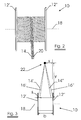
- FIGURE 1 shows a spool 10 according to a first embodiment of the first aspect of the present invention.
- the spool 10 is provided with two flanges 12' and 12".
- Two steel cords 14 and 16 both twisted in S-direction, are wound in parallel and adjacent to each other on spool 10.
- the distance s, as measured along a line parallel to the axis 18 of spool 10, is less than 5 mm.
- FIGURE 2 shows a spool 10 according to a particular and second embodiment of the first aspect of the present invention.
- the spool 10 is provided with two flanges 12' and 12".
- a steel cord 14, twisted in S-direction, and a steel cord 20, twisted in Z-direction, are wound in parallel and adjacent to each other on spool 10.
- the distance s, as measured along a line parallel to the axis 18 of spool 10, is less than 5 mm.
- any residual torsions present on S-cords may compensate on average any residual torsions present on Z-cords so that eventually cut composite strips rubber - steel cord do not exhibit curling.
- residual torsions are defined as follows : if one end of a specified length of cord is allowed to turn freely, the number of residual torsions is equal to the number of revolutions counted.
- An imbalance of residual torsions over the totality of steel cords within one composite strip rubber - steel cord is known as the main cause of curling. Avoiding this imbalance reduces the risk for curling. And, as explained above, avoidance of curling may facilitate the automated handling of the strips. In such configuration it is sufficient that the steel cords present in the cut strips have on average no residual torsions. As a result it is no longer required to fine-tune the amount of residual torsions present on each single steel cord during its twisting step. This may considerably reduce the auxiliary equipment required, more particularly, the automatic torsion control may be cancelled.
- FIGURE 3 explains the basic working of the present invention.
- Spool 10 is filled with two steel cords 14, 16. There is a distance s present between the two steel cords 14 and 16, measured along a line parallel to the axis 18 of the spool 10.
- the two steel cords 14, 16 are wound from spool 10 and are guided through one single fixed hole 22.
- Steel cords 14' and 16' show the situation at the left flange 12' and steel cords 14" and 16" show the situation at the right flange 12".
- the distance s is supposed to remain constant during the unwinding process.
- the spool width b is equal to 153 mm.
- the steel cord is of a 2x0.30 type, so that the cross-section A is equal to 0.141372 mm 2 .
- l 1 is the length of the unwound cord 14'.
- l 2 the length of the unwound cord 16'
- l 3 the length of the unwound cord 14"
- l 4 the length of the unwound cord 16".
- the underlying layer consisting of the same type of elongated elements, the underlying layer is rough. So it is not always possible to keep the distance s constant during winding. Nevertheless measures should be taken to keep the distance between the neighboring elongated elements as small as possible.
Landscapes
- Ropes Or Cables (AREA)
- Storage Of Web-Like Or Filamentary Materials (AREA)
- Joining Of Building Structures In Genera (AREA)
- Iron Core Of Rotating Electric Machines (AREA)
- Winding Filamentary Materials (AREA)
- Guides For Winding Or Rewinding, Or Guides For Filamentary Materials (AREA)
- Filamentary Materials, Packages, And Safety Devices Therefor (AREA)
- Unwinding Of Filamentary Materials (AREA)
Abstract
Description
- The present invention relates to a spool filled with two or more elongated elements wound in parallel and in several windings upon the spool. The present invention also relates to a method of providing such a spool. The terms 'elongated elements' refer to elements the longitudinal dimension of which is more than hundred times larger than the cross-sectional dimensions. Common examples of elongated elements are round or flat steel wires, steel cords, ...
- Assemblies and apparatus for winding a plurality of elongated elements such as wires, cables or cords on one single spool are known in the art.
- As a matter of example, when manufacturing composites of rubber with steel cord, such as tires, the steel cords are very often drawn from a creel, which comprises a large number of spools, e.g. 20 to 150 spools in some embodiments and e.g. 500 to 1000 spools in other embodiments. The great number of steel cords is then guided in parallel in order to be inserted between two layers of rubber. A drawback of such a system is that it takes a lot of time to replace the empty spools by filled spools. Using spools with multiple winding, i.e. where a plurality of steel cords is wound upon one spool, reduces the number of spools in a creel and increases the flexibility of the use of such a creel.
- However, the simultaneous unwinding of a plurality of elongated elements from such a single spool, may cause difficulties and the subsequent parallel processing of the plurality of elongated elements may lead to an unacceptable degree of fractures and processability problems.
The unwinding difficulties and the processability problems and fractures during the subsequent treatment may be due to a variation in diameter of the elongated elements during their winding, or may be due to the fact that elongated elements become entangled during their winding, or may be due to the fact that the elongated elements, although wound at the same time on the same spool, take different lengths on the spool.
Other difficulties during the unwinding operations are due to different tensions in the individual elongated elements during the winding operation. - GB-B-1 163 983 discloses a method for winding a plurality of elongated elements on one single spool whereby it is aimed at keeping the winding lengths of the elongated elements substantially equal to each other despite some variations in diameter of the elongated element. The solution used to obtain substantially the same lengths is to increase the tension in elongated elements with an increased diameter in order to reduce the winding diameter and to decrease the tension in elongated elements with a decreased diameter in order to increase the winding diameter. A separation comb is mounted upstream the winding spool in order to avoid disentanglement of the neighboring elongated elements.
- EP-A-0 780 333 discloses an assembly for winding multiple elongated elements on a spool, where the tensions in the elongated elements, for example steel wires or steel cords, are kept substantially constant and equal. In order to obtain constant and equal tensions, the assembly comprises following parts :
- a set of independently driveable capstans, one for each individual elongated element to be wound ;
- a single spool where the plurality of elongated elements are to be wound ;
- first monitoring means for measuring the tensions of each individual elongated element of a subgroup of the plurality of elongated elements ;
- first control means for steering individually the revolution speed of the capstans driving the elongated elements of the subgroup such that said tensions remain substantially constant and substantially equal to each other.
- So the prior art has provided solutions both for keeping the lengths equal and the tensions constant in the elongated elements to be wound.
- Despite these solutions problems are still experienced in determined circumstances when unwinding the plurality of elongated elements at the same time. More particularly, when unwinding, some of the elongated elements show unacceptable large sags. These sags may lead to entanglement with the neighboring elements or to wear or pollution of the sagged elements when these elements drag over the floor of the unwinding shop. Still another problem is that the ultimate product, e.g. a rubber strip with the elongated elements may show some unacceptable wrinkles. Both prior art documents EP-A-0 113 671 and EP-A-0 299 506 disclose the winding of glass yarns or glass filaments.
- It is an object of the present invention to avoid the drawbacks of the prior art.
It is another object of the present invention to minimize unwinding problems.
It is yet another object of the present invention to minimize sags during the unwinding of the plurality of elongated elements.
It is still another object of the present invention to avoid wrinkles in the ultimate product. - According to a first aspect of the present invention there is provided a spool filled with two or more elongated steel elements wound in parallel and in several windings upon the spool. The distance between two neighboring elongated steel elements, as measured along a line parallel to the axis of the spool, is not more than 10 mm, preferably not more than 8 mm, e.g. not more than 5 mm, along 90% of the length of each elongated element.
- Indeed the inventors have experienced that the distance between the neighboring elongated steel elements wound on the spool is a critical parameter. It does not only suffice to wind the elongated elements under substantially equal tensions and to wind the elongated elements with substantially equal lengths upon the spool, the elongated elements have also to be wound as close as possible to each other without becoming entangled. As will be explained hereinafter, the greater the distance between two neighboring elongated elements, the greater the danger for tension differences in the unwinding elongated elements - even if the elongated elements have been wound under equal tensions and with equal lengths. The greater the tension differences in the unwinding elongated elements the greater the danger for sags in one or more of the elongated elements and the greater the danger for wrinkles in the ultimate product.
- The steel elements may be steel wires or steel cords.
- In a particular embodiment of the invention, there is provided a spool wherein one of the steel cords comprises steel filaments, a majority of which is twisted in a first twist direction, and wherein another of the steel cords also comprises steel filaments, a majority of which is twisted in a second twist direction. The second twist direction is opposite to the first twist direction.
Preferably the spool comprises two steel cords wound upon the spool. One steel cord is mainly twisted in an S-direction and the other steel cord is mainly twisted in a Z-direction. - According to a second aspect of the present invention, there is provided a method of minimizing sags when unwinding multiple elongated elements from one single spool. The method comprises the following steps :
- a) providing a spool ;
- b) winding multiple elongated steel elements in parallel and in several windings upon the spool so that that the distance between two neighboring elongated elements, as measured along a line parallel to the axis of the spool, is not more than 10 mm along 90% of the length of each elongated element.
- In a preferable embodiment of the method the multiple elongated elements are guided on a common pulley just upstream the spool in order to reduce as much as possible the distance s between two neighboring elongated elements on the spool. The common pulley is located as close as possible to the spool.
- Most preferably the multiple elongated elements are kept separate from each other upstream the common pulley in order to avoid that the elongated elements would entangle with each other.
- The common pulley preferably has a flat groove and most preferably the width of this groove is somewhat greater than the sum of the diameters of the multiple elongated elements. This gives the best results with respect to minimizing the distance s while still avoiding the entanglement between two neighboring elongated elements.
- The invention will now be described into more detail with reference to the accompanying drawings wherein
- FIGURE 1 shows a spool according to a first embodiment of the present invention ;
- FIGURE 2 shows a spool according to a second and particular embodiment of the present invention ;
- FIGURE 3 gives a schematic drawing explaining the working of the present invention.
- FIGURE 1 shows a
spool 10 according to a first embodiment of the first aspect of the present invention. Thespool 10 is provided with twoflanges 12' and 12". Twosteel cords spool 10. The distance s, as measured along a line parallel to theaxis 18 ofspool 10, is less than 5 mm. - FIGURE 2 shows a
spool 10 according to a particular and second embodiment of the first aspect of the present invention. Thespool 10 is provided with twoflanges 12' and 12". Asteel cord 14, twisted in S-direction, and asteel cord 20, twisted in Z-direction, are wound in parallel and adjacent to each other onspool 10. The distance s, as measured along a line parallel to theaxis 18 ofspool 10, is less than 5 mm. When using spools according to this particular embodiment of the invention on a creel in the field of rubber tires, an S-cord and a Z-cord will lie, one adjacent to the other in a composite ply rubber-steel cord. If all the spools on the creel will be spools according to the invention, there will be an equal number of S-cords and Z-cords on average over the whole composite rubber - steel cord ply. S-cords will alternate on average with Z-cords over the whole composite ply. In such a configuration it is likely that any residual torsions present on S-cords may compensate on average any residual torsions present on Z-cords so that eventually cut composite strips rubber - steel cord do not exhibit curling. Within the context of the present invention, the terms "residual torsions" are defined as follows : if one end of a specified length of cord is allowed to turn freely, the number of residual torsions is equal to the number of revolutions counted. An imbalance of residual torsions over the totality of steel cords within one composite strip rubber - steel cord is known as the main cause of curling. Avoiding this imbalance reduces the risk for curling. And, as explained above, avoidance of curling may facilitate the automated handling of the strips. In such configuration it is sufficient that the steel cords present in the cut strips have on average no residual torsions. As a result it is no longer required to fine-tune the amount of residual torsions present on each single steel cord during its twisting step. This may considerably reduce the auxiliary equipment required, more particularly, the automatic torsion control may be cancelled. - FIGURE 3 explains the basic working of the present invention.
Spool 10 is filled with twosteel cords steel cords axis 18 of thespool 10. The twosteel cords spool 10 and are guided through one singlefixed hole 22. Steel cords 14' and 16' show the situation at the left flange 12' andsteel cords 14" and 16" show the situation at theright flange 12".
For the sake of the current calculations, the distance s is supposed to remain constant during the unwinding process.
Also for the sake of calculations, thehole 22 is supposed to be at a distance of y = 3000 mm from thespool 10, and at x = 0 mm from the extension ofright flange 12".
The spool width b is equal to 153 mm.
It is further supposed that the steel cord is of a 2x0.30 type, so that the cross-section A is equal to 0.141372 mm2.
l1 is the length of the unwoundcord 14'. l2 the length of the unwound cord 16', l3 the length of the unwoundcord 14" and l4 the length of the unwoundcord 16".
With the above assumptions, at with a value of intercord distance s equal to 10 mm, we obtain following values for the various lengths l1, l2, l3, and l4 :


The difference of the length difference, i.e. the change in length difference between the situation at the left flange 12' and the length difference at theright flange 12" is :
Such a change in length difference results in a change in tension difference of
With an intercord distance s different from 0 mm, the length difference between the unwoundsteel cords steel cords
This change in tension difference is dependent upon the distance s and increases as the distance s increases, as may be derived from the following table.Table : tension difference in function of distance s s [mm] Δσ (Newton) 0 0 0,5 0,239236 1 0,476904 1,5 0,713005 2 0,947537 2,5 1,180502 3 1,411899 3,5 1,641728 4 1,86999 4,5 2,096683 5 2,321809 5,5 2,545366 6 2,767356 6,5 2,987777 7 3,206631 7,5 3,423917 8 3,639634 8,5 3,853784 9 4,066365 9,5 4,277379 10 4,486824 10,5 4,694701 11 4,901 - Dependent upon the unwinding tension applied to the spool, which may vary from 400 gram (= 3.924 Newton) to 3 kg (= 29.43 Newton), considerable sags up to 0.5 m and higher may be registered. Sags occur each time the tension in one elongated element becomes zero. More exactly, when the difference between the unwinding tension applied to the spool (this is the sum of the unwinding tensions of the individual elongated elements) and the tension difference between the individual elongated elements becomes smaller than zero, one of the elongated elements will form a sag.
The above simulation and calculation shows that it is important to keep the distance s between the neighboring elongated elements as small as possible.
The underlying layer consisting of the same type of elongated elements, the underlying layer is rough. So it is not always possible to keep the distance s constant during winding. Nevertheless measures should be taken to keep the distance between the neighboring elongated elements as small as possible.
Claims (10)
- A spool filled with two or more elongated steel elements wound in parallel and in several windings upon said spool, characterized in that the distance between two neighboring elongated steel elements, as measured along a line parallel to the axis of the spool, is not more than 10 mm along 90% of the length of each elongated steel element.
- A spool according to claim 1 wherein said distance is smaller than 5 mm.
- A spool according to claim 1 wherein said steel elements are steel wires.
- A spool according to claim 1 wherein said steel elements are steel cords.
- A spool according to claim 4 wherein one of said steel cords comprises steel filaments, a majority of which being twisted in a first twist direction, and wherein another of said steel cords comprises steel filaments, a majority of which being twisted in a second twist direction, said second twist direction being opposite to said first twist direction.
- A method of minimizing sags when unwinding multiple elongated steel elements from one single spool, said method comprising the following steps :a) providing a spool ;b) winding multiple elongated steel elements in parallel and in several windings upon said spool so that that the distance between two neighboring elongated steel elements, as measured along a line parallel to the axis of the spool, is not more than 10 mm along 90% of the length of each elongated element.
- A method according to claim 6 wherein said method further comprises the following step :- guiding the multiple elongated steel elements on a common pulley upstream the spool.
- A method according to claim 7 wherein said method further comprises the following step :- keeping the multiple elongated steel elements separate from each other upstream said common pulley.
- A method according to claim 8 wherein said common pulley has a flat groove.
- A method according to claim 9 wherein said flat groove has a width being greater than the sum of the diameters of the multiple elongated elements.
Priority Applications (1)
| Application Number | Priority Date | Filing Date | Title |
|---|---|---|---|
| EP02792875A EP1485314B1 (en) | 2002-03-13 | 2002-12-03 | Spool filled with multiple elongated elements wound closely together |
Applications Claiming Priority (4)
| Application Number | Priority Date | Filing Date | Title |
|---|---|---|---|
| EP02100243 | 2002-03-13 | ||
| EP02100243 | 2002-03-13 | ||
| EP02792875A EP1485314B1 (en) | 2002-03-13 | 2002-12-03 | Spool filled with multiple elongated elements wound closely together |
| PCT/EP2002/013688 WO2003076321A1 (en) | 2002-03-13 | 2002-12-03 | Spool filled with multiple elongated elements wound closely together |
Publications (2)
| Publication Number | Publication Date |
|---|---|
| EP1485314A1 EP1485314A1 (en) | 2004-12-15 |
| EP1485314B1 true EP1485314B1 (en) | 2006-10-18 |
Family
ID=27798897
Family Applications (1)
| Application Number | Title | Priority Date | Filing Date |
|---|---|---|---|
| EP02792875A Expired - Lifetime EP1485314B1 (en) | 2002-03-13 | 2002-12-03 | Spool filled with multiple elongated elements wound closely together |
Country Status (12)
| Country | Link |
|---|---|
| US (1) | US7185838B2 (en) |
| EP (1) | EP1485314B1 (en) |
| JP (1) | JP2005519827A (en) |
| KR (1) | KR20040089614A (en) |
| CN (1) | CN1289372C (en) |
| AT (1) | ATE342861T1 (en) |
| AU (1) | AU2002358591A1 (en) |
| DE (1) | DE60215553T2 (en) |
| EA (1) | EA005968B1 (en) |
| ES (1) | ES2272804T3 (en) |
| PT (1) | PT1485314E (en) |
| WO (1) | WO2003076321A1 (en) |
Families Citing this family (17)
| Publication number | Priority date | Publication date | Assignee | Title |
|---|---|---|---|---|
| US8800967B2 (en) | 2009-03-23 | 2014-08-12 | Southwire Company, Llc | Integrated systems facilitating wire and cable installations |
| US9802785B2 (en) | 2008-01-21 | 2017-10-31 | Southwire Company, Llc | Systems and methods for facilitating wire and cable installations |
| US10003179B2 (en) * | 2008-01-21 | 2018-06-19 | Southwire Company, Llc | Integrated systems facilitating wire and cable installations |
| GB0818922D0 (en) | 2008-10-16 | 2008-11-19 | Otv Sa | Component, method and system of sanitising a water purification apparatus and/or a distribution apparatus |
| ITRN20080057A1 (en) * | 2008-12-04 | 2009-03-05 | Lisciani Trafilerie Srl R | EXTRACT COIL FOR IRON THREADS FOR BINDING |
| US8936153B1 (en) | 2011-05-04 | 2015-01-20 | Southwire Company, Llc | Multiple conductor container |
| AU2012285834B2 (en) * | 2011-07-21 | 2016-02-25 | Commscope Technologies Llc | Method for extruding a drop cable |
| US9027908B1 (en) | 2011-09-01 | 2015-05-12 | Southwire Company, Llc | Field-installable pulling eye |
| US9867300B1 (en) | 2012-05-04 | 2018-01-09 | Southwire Company, Llc | Multiple conductor container |
| US10232868B1 (en) | 2012-05-04 | 2019-03-19 | Southwire Company, Llc | Container for storing conductors |
| CN104338873A (en) | 2013-07-29 | 2015-02-11 | 贝卡尔特公司 | Straight monofilament for belt |
| CN104787618A (en) * | 2015-04-20 | 2015-07-22 | 江苏胜达科技有限公司 | Waste wire processing device |
| SMT202400349T1 (en) * | 2015-07-22 | 2024-11-15 | Max Co Ltd | Reel for binding machine |
| CA2941006C (en) | 2015-09-01 | 2024-01-16 | Southwire Company, Llc | Conductor identification |
| GB2562458A (en) | 2017-03-17 | 2018-11-21 | Vws Uk Ltd | Method for providing ultrapure water |
| CN107444994B (en) * | 2017-07-25 | 2023-08-01 | 杭州舜海光伏科技有限公司 | Rope winding and unwinding device and cleaning equipment |
| CN111942959A (en) * | 2020-07-20 | 2020-11-17 | 陕西天元智能再制造股份有限公司 | A kind of side-by-side double-ended winding coiled welding wire and its preparation method and use |
Family Cites Families (9)
| Publication number | Priority date | Publication date | Assignee | Title |
|---|---|---|---|---|
| US2187841A (en) * | 1935-11-29 | 1940-01-23 | Nat Standard Co | Wire winding apparatus |
| GB1163983A (en) * | 1967-03-28 | 1969-09-10 | Bekaert Pvba Leon | Improvements relating to the Winding of Strand Material |
| US4488686A (en) * | 1983-01-10 | 1984-12-18 | Ppg Industries, Inc. | Apparatus and method for packaging a plurality of filaments or bundles of filaments |
| JPS61186585A (en) * | 1985-02-12 | 1986-08-20 | 住友電気工業株式会社 | Bobbin wound steel code |
| JPS6362467A (en) * | 1986-09-03 | 1988-03-18 | Matsushita Graphic Commun Syst Inc | Facsimile procedure method |
| JPS6424047A (en) * | 1987-07-17 | 1989-01-26 | Nitto Glass Fiber Mfg | Production of glass yarn |
| JPH04308166A (en) * | 1991-04-05 | 1992-10-30 | Nippondenso Co Ltd | Guide device for winding machine |
| EP0780333A1 (en) * | 1995-12-18 | 1997-06-25 | N.V. Bekaert S.A. | Winding of multiple filaments |
| TW200636771A (en) * | 2005-03-03 | 2006-10-16 | Nittoku Eng | Multilayer coil, winding method of same, and winding apparatus of same |
-
2002
- 2002-12-03 ES ES02792875T patent/ES2272804T3/en not_active Expired - Lifetime
- 2002-12-03 KR KR10-2004-7012400A patent/KR20040089614A/en not_active Ceased
- 2002-12-03 US US10/507,503 patent/US7185838B2/en not_active Expired - Lifetime
- 2002-12-03 DE DE60215553T patent/DE60215553T2/en not_active Expired - Lifetime
- 2002-12-03 AT AT02792875T patent/ATE342861T1/en not_active IP Right Cessation
- 2002-12-03 CN CNB028284259A patent/CN1289372C/en not_active Expired - Lifetime
- 2002-12-03 WO PCT/EP2002/013688 patent/WO2003076321A1/en not_active Ceased
- 2002-12-03 EP EP02792875A patent/EP1485314B1/en not_active Expired - Lifetime
- 2002-12-03 PT PT02792875T patent/PT1485314E/en unknown
- 2002-12-03 AU AU2002358591A patent/AU2002358591A1/en not_active Abandoned
- 2002-12-03 EA EA200401196A patent/EA005968B1/en not_active IP Right Cessation
- 2002-12-03 JP JP2003574552A patent/JP2005519827A/en active Pending
Also Published As
| Publication number | Publication date |
|---|---|
| US7185838B2 (en) | 2007-03-06 |
| EA005968B1 (en) | 2005-08-25 |
| JP2005519827A (en) | 2005-07-07 |
| WO2003076321A1 (en) | 2003-09-18 |
| EA200401196A1 (en) | 2005-02-24 |
| DE60215553T2 (en) | 2007-06-06 |
| CN1289372C (en) | 2006-12-13 |
| KR20040089614A (en) | 2004-10-21 |
| DE60215553D1 (en) | 2006-11-30 |
| PT1485314E (en) | 2007-01-31 |
| EP1485314A1 (en) | 2004-12-15 |
| AU2002358591A1 (en) | 2003-09-22 |
| CN1622913A (en) | 2005-06-01 |
| ATE342861T1 (en) | 2006-11-15 |
| US20050139706A1 (en) | 2005-06-30 |
| ES2272804T3 (en) | 2007-05-01 |
Similar Documents
| Publication | Publication Date | Title |
|---|---|---|
| US7185838B2 (en) | Spool filled with multiple elongated elements wound closely together | |
| CN101680133B (en) | Method for plying filaments and filament bundle produced by the method | |
| KR102199539B1 (en) | Straight steel monofilament for a belt ply | |
| EP0143732B1 (en) | Apparatus and process of manufacturing a metal cord | |
| EP0780333A1 (en) | Winding of multiple filaments | |
| JP5254887B2 (en) | Wire rod winding device and winding method | |
| JP4666555B2 (en) | Winding multiple bundles of steel wire | |
| JP2008025040A (en) | Steel cord and manufacturing method thereof | |
| JPS58128238A (en) | Manufacture of bead ring | |
| JP3197604B2 (en) | Manufacturing method of rubber sheet containing wire | |
| JP2596348Y2 (en) | Straightening device in twisting machine | |
| JP2568454Y2 (en) | Steel cord for rubber reinforcement | |
| JP2006007428A (en) | Rubber sheet manufacturing method | |
| JP2009235640A (en) | Steel cord, and steel cord cluster consisting of the steel cords | |
| KR200190508Y1 (en) | Apparatus for preventing wire separation of steel cord twister | |
| JPS6211936B2 (en) | ||
| JP5623105B2 (en) | Steel cord manufacturing method | |
| WO2024145042A1 (en) | Method and configuration for connecting roving assemblies | |
| JP2009299219A (en) | Method for producing rubber steel cord composite material | |
| CN119301323A (en) | Twisting machine with replaceable bobbin carrier | |
| JP2013209769A (en) | Manufacturing method of steel cord and steel cord provided thereby | |
| JPH1025678A (en) | Steel cord for reinforcement of rubber article, its production facility and pneumatic radial tire | |
| JPH07166484A (en) | Steel cord for reinforcing rubber article and composite material thereof |
Legal Events
| Date | Code | Title | Description |
|---|---|---|---|
| PUAI | Public reference made under article 153(3) epc to a published international application that has entered the european phase |
Free format text: ORIGINAL CODE: 0009012 |
|
| 17P | Request for examination filed |
Effective date: 20040827 |
|
| AK | Designated contracting states |
Kind code of ref document: A1 Designated state(s): AT BE BG CH CY CZ DE DK EE ES FI FR GB GR IE IT LI LU MC NL PT SE SI SK TR |
|
| AX | Request for extension of the european patent |
Extension state: AL LT LV MK RO |
|
| RIN1 | Information on inventor provided before grant (corrected) |
Inventor name: VANNESTE, STIJN Inventor name: MULLEBROUCK, RIK Inventor name: SABBE, LUC |
|
| GRAP | Despatch of communication of intention to grant a patent |
Free format text: ORIGINAL CODE: EPIDOSNIGR1 |
|
| GRAS | Grant fee paid |
Free format text: ORIGINAL CODE: EPIDOSNIGR3 |
|
| GRAA | (expected) grant |
Free format text: ORIGINAL CODE: 0009210 |
|
| AK | Designated contracting states |
Kind code of ref document: B1 Designated state(s): AT BE BG CH CY CZ DE DK EE ES FI FR GB GR IE IT LI LU MC NL PT SE SI SK TR |
|
| PG25 | Lapsed in a contracting state [announced via postgrant information from national office to epo] |
Ref country code: LI Free format text: LAPSE BECAUSE OF FAILURE TO SUBMIT A TRANSLATION OF THE DESCRIPTION OR TO PAY THE FEE WITHIN THE PRESCRIBED TIME-LIMIT Effective date: 20061018 Ref country code: CH Free format text: LAPSE BECAUSE OF FAILURE TO SUBMIT A TRANSLATION OF THE DESCRIPTION OR TO PAY THE FEE WITHIN THE PRESCRIBED TIME-LIMIT Effective date: 20061018 Ref country code: AT Free format text: LAPSE BECAUSE OF FAILURE TO SUBMIT A TRANSLATION OF THE DESCRIPTION OR TO PAY THE FEE WITHIN THE PRESCRIBED TIME-LIMIT Effective date: 20061018 Ref country code: SI Free format text: LAPSE BECAUSE OF FAILURE TO SUBMIT A TRANSLATION OF THE DESCRIPTION OR TO PAY THE FEE WITHIN THE PRESCRIBED TIME-LIMIT Effective date: 20061018 |
|
| REG | Reference to a national code |
Ref country code: GB Ref legal event code: FG4D |
|
| REG | Reference to a national code |
Ref country code: CH Ref legal event code: EP Ref country code: IE Ref legal event code: FG4D |
|
| PGFP | Annual fee paid to national office [announced via postgrant information from national office to epo] |
Ref country code: BE Payment date: 20061123 Year of fee payment: 5 Ref country code: GB Payment date: 20061123 Year of fee payment: 5 |
|
| REF | Corresponds to: |
Ref document number: 60215553 Country of ref document: DE Date of ref document: 20061130 Kind code of ref document: P |
|
| PG25 | Lapsed in a contracting state [announced via postgrant information from national office to epo] |
Ref country code: IE Free format text: LAPSE BECAUSE OF NON-PAYMENT OF DUE FEES Effective date: 20061204 |
|
| PGFP | Annual fee paid to national office [announced via postgrant information from national office to epo] |
Ref country code: BG Payment date: 20061215 Year of fee payment: 5 |
|
| PG25 | Lapsed in a contracting state [announced via postgrant information from national office to epo] |
Ref country code: MC Free format text: LAPSE BECAUSE OF NON-PAYMENT OF DUE FEES Effective date: 20061231 |
|
| PG25 | Lapsed in a contracting state [announced via postgrant information from national office to epo] |
Ref country code: SE Free format text: LAPSE BECAUSE OF FAILURE TO SUBMIT A TRANSLATION OF THE DESCRIPTION OR TO PAY THE FEE WITHIN THE PRESCRIBED TIME-LIMIT Effective date: 20070118 Ref country code: DK Free format text: LAPSE BECAUSE OF FAILURE TO SUBMIT A TRANSLATION OF THE DESCRIPTION OR TO PAY THE FEE WITHIN THE PRESCRIBED TIME-LIMIT Effective date: 20070118 |
|
| REG | Reference to a national code |
Ref country code: PT Ref legal event code: SC4A Free format text: AVAILABILITY OF NATIONAL TRANSLATION Effective date: 20061205 |
|
| ET | Fr: translation filed | ||
| REG | Reference to a national code |
Ref country code: CH Ref legal event code: PL |
|
| REG | Reference to a national code |
Ref country code: ES Ref legal event code: FG2A Ref document number: 2272804 Country of ref document: ES Kind code of ref document: T3 |
|
| PLBE | No opposition filed within time limit |
Free format text: ORIGINAL CODE: 0009261 |
|
| STAA | Information on the status of an ep patent application or granted ep patent |
Free format text: STATUS: NO OPPOSITION FILED WITHIN TIME LIMIT |
|
| 26N | No opposition filed |
Effective date: 20070719 |
|
| PG25 | Lapsed in a contracting state [announced via postgrant information from national office to epo] |
Ref country code: GR Free format text: LAPSE BECAUSE OF FAILURE TO SUBMIT A TRANSLATION OF THE DESCRIPTION OR TO PAY THE FEE WITHIN THE PRESCRIBED TIME-LIMIT Effective date: 20070119 |
|
| BERE | Be: lapsed |
Owner name: N.V. BEKAERT S.A. Effective date: 20071231 |
|
| PG25 | Lapsed in a contracting state [announced via postgrant information from national office to epo] |
Ref country code: EE Free format text: LAPSE BECAUSE OF FAILURE TO SUBMIT A TRANSLATION OF THE DESCRIPTION OR TO PAY THE FEE WITHIN THE PRESCRIBED TIME-LIMIT Effective date: 20061018 |
|
| GBPC | Gb: european patent ceased through non-payment of renewal fee |
Effective date: 20071203 |
|
| PG25 | Lapsed in a contracting state [announced via postgrant information from national office to epo] |
Ref country code: BE Free format text: LAPSE BECAUSE OF NON-PAYMENT OF DUE FEES Effective date: 20071231 |
|
| PG25 | Lapsed in a contracting state [announced via postgrant information from national office to epo] |
Ref country code: BG Free format text: LAPSE BECAUSE OF NON-PAYMENT OF DUE FEES Effective date: 20080630 |
|
| PG25 | Lapsed in a contracting state [announced via postgrant information from national office to epo] |
Ref country code: CY Free format text: LAPSE BECAUSE OF FAILURE TO SUBMIT A TRANSLATION OF THE DESCRIPTION OR TO PAY THE FEE WITHIN THE PRESCRIBED TIME-LIMIT Effective date: 20061018 |
|
| PG25 | Lapsed in a contracting state [announced via postgrant information from national office to epo] |
Ref country code: GB Free format text: LAPSE BECAUSE OF NON-PAYMENT OF DUE FEES Effective date: 20071203 |
|
| PGFP | Annual fee paid to national office [announced via postgrant information from national office to epo] |
Ref country code: CZ Payment date: 20081124 Year of fee payment: 7 Ref country code: NL Payment date: 20081223 Year of fee payment: 7 |
|
| PGFP | Annual fee paid to national office [announced via postgrant information from national office to epo] |
Ref country code: FI Payment date: 20081230 Year of fee payment: 7 Ref country code: PT Payment date: 20081125 Year of fee payment: 7 |
|
| REG | Reference to a national code |
Ref country code: PT Ref legal event code: MM4A Free format text: LAPSE DUE TO NON-PAYMENT OF FEES Effective date: 20100604 |
|
| REG | Reference to a national code |
Ref country code: NL Ref legal event code: V1 Effective date: 20100701 |
|
| PG25 | Lapsed in a contracting state [announced via postgrant information from national office to epo] |
Ref country code: PT Free format text: LAPSE BECAUSE OF NON-PAYMENT OF DUE FEES Effective date: 20100604 |
|
| PG25 | Lapsed in a contracting state [announced via postgrant information from national office to epo] |
Ref country code: FI Free format text: LAPSE BECAUSE OF NON-PAYMENT OF DUE FEES Effective date: 20091203 Ref country code: CZ Free format text: LAPSE BECAUSE OF NON-PAYMENT OF DUE FEES Effective date: 20091203 |
|
| PG25 | Lapsed in a contracting state [announced via postgrant information from national office to epo] |
Ref country code: NL Free format text: LAPSE BECAUSE OF NON-PAYMENT OF DUE FEES Effective date: 20100701 |
|
| REG | Reference to a national code |
Ref country code: FR Ref legal event code: PLFP Year of fee payment: 14 |
|
| REG | Reference to a national code |
Ref country code: FR Ref legal event code: PLFP Year of fee payment: 15 |
|
| REG | Reference to a national code |
Ref country code: FR Ref legal event code: PLFP Year of fee payment: 16 |
|
| PGFP | Annual fee paid to national office [announced via postgrant information from national office to epo] |
Ref country code: LU Payment date: 20191219 Year of fee payment: 18 |
|
| PG25 | Lapsed in a contracting state [announced via postgrant information from national office to epo] |
Ref country code: LU Free format text: LAPSE BECAUSE OF NON-PAYMENT OF DUE FEES Effective date: 20201203 |
|
| PGFP | Annual fee paid to national office [announced via postgrant information from national office to epo] |
Ref country code: FR Payment date: 20211224 Year of fee payment: 20 Ref country code: DE Payment date: 20211210 Year of fee payment: 20 Ref country code: SK Payment date: 20211202 Year of fee payment: 20 Ref country code: TR Payment date: 20211202 Year of fee payment: 20 |
|
| PGFP | Annual fee paid to national office [announced via postgrant information from national office to epo] |
Ref country code: IT Payment date: 20211224 Year of fee payment: 20 Ref country code: ES Payment date: 20220218 Year of fee payment: 20 |
|
| REG | Reference to a national code |
Ref country code: DE Ref legal event code: R071 Ref document number: 60215553 Country of ref document: DE |
|
| REG | Reference to a national code |
Ref country code: SK Ref legal event code: MK4A Ref document number: E 1334 Country of ref document: SK Expiry date: 20221203 |
|
| PG25 | Lapsed in a contracting state [announced via postgrant information from national office to epo] |
Ref country code: SK Free format text: LAPSE BECAUSE OF EXPIRATION OF PROTECTION Effective date: 20221203 |
|
| REG | Reference to a national code |
Ref country code: ES Ref legal event code: FD2A Effective date: 20230428 |
|
| PG25 | Lapsed in a contracting state [announced via postgrant information from national office to epo] |
Ref country code: ES Free format text: LAPSE BECAUSE OF EXPIRATION OF PROTECTION Effective date: 20221204 |