EP1485134B1 - Method and device for measuring and controlling the circulation of fluids in endoscope channels - Google Patents
Method and device for measuring and controlling the circulation of fluids in endoscope channels Download PDFInfo
- Publication number
- EP1485134B1 EP1485134B1 EP20030718874 EP03718874A EP1485134B1 EP 1485134 B1 EP1485134 B1 EP 1485134B1 EP 20030718874 EP20030718874 EP 20030718874 EP 03718874 A EP03718874 A EP 03718874A EP 1485134 B1 EP1485134 B1 EP 1485134B1
- Authority
- EP
- European Patent Office
- Prior art keywords
- endoscope
- channels
- vessel
- channel
- chamber
- Prior art date
- Legal status (The legal status is an assumption and is not a legal conclusion. Google has not performed a legal analysis and makes no representation as to the accuracy of the status listed.)
- Expired - Lifetime
Links
Images
Classifications
-
- A—HUMAN NECESSITIES
- A61—MEDICAL OR VETERINARY SCIENCE; HYGIENE
- A61B—DIAGNOSIS; SURGERY; IDENTIFICATION
- A61B1/00—Instruments for performing medical examinations of the interior of cavities or tubes of the body by visual or photographical inspection, e.g. endoscopes; Illuminating arrangements therefor
- A61B1/12—Instruments for performing medical examinations of the interior of cavities or tubes of the body by visual or photographical inspection, e.g. endoscopes; Illuminating arrangements therefor with cooling or rinsing arrangements
- A61B1/121—Instruments for performing medical examinations of the interior of cavities or tubes of the body by visual or photographical inspection, e.g. endoscopes; Illuminating arrangements therefor with cooling or rinsing arrangements provided with means for cleaning post-use
- A61B1/123—Instruments for performing medical examinations of the interior of cavities or tubes of the body by visual or photographical inspection, e.g. endoscopes; Illuminating arrangements therefor with cooling or rinsing arrangements provided with means for cleaning post-use using washing machines
-
- A—HUMAN NECESSITIES
- A61—MEDICAL OR VETERINARY SCIENCE; HYGIENE
- A61B—DIAGNOSIS; SURGERY; IDENTIFICATION
- A61B1/00—Instruments for performing medical examinations of the interior of cavities or tubes of the body by visual or photographical inspection, e.g. endoscopes; Illuminating arrangements therefor
- A61B1/12—Instruments for performing medical examinations of the interior of cavities or tubes of the body by visual or photographical inspection, e.g. endoscopes; Illuminating arrangements therefor with cooling or rinsing arrangements
- A61B1/121—Instruments for performing medical examinations of the interior of cavities or tubes of the body by visual or photographical inspection, e.g. endoscopes; Illuminating arrangements therefor with cooling or rinsing arrangements provided with means for cleaning post-use
- A61B1/125—Instruments for performing medical examinations of the interior of cavities or tubes of the body by visual or photographical inspection, e.g. endoscopes; Illuminating arrangements therefor with cooling or rinsing arrangements provided with means for cleaning post-use using fluid circuits
-
- A—HUMAN NECESSITIES
- A61—MEDICAL OR VETERINARY SCIENCE; HYGIENE
- A61L—METHODS OR APPARATUS FOR STERILISING MATERIALS OR OBJECTS IN GENERAL; DISINFECTION, STERILISATION OR DEODORISATION OF AIR; CHEMICAL ASPECTS OF BANDAGES, DRESSINGS, ABSORBENT PADS OR SURGICAL ARTICLES; MATERIALS FOR BANDAGES, DRESSINGS, ABSORBENT PADS OR SURGICAL ARTICLES
- A61L2/00—Methods or apparatus for disinfecting or sterilising materials or objects other than foodstuffs or contact lenses; Accessories therefor
- A61L2/16—Methods or apparatus for disinfecting or sterilising materials or objects other than foodstuffs or contact lenses; Accessories therefor using chemical substances
- A61L2/18—Liquid substances or solutions comprising solids or dissolved gases
-
- A—HUMAN NECESSITIES
- A61—MEDICAL OR VETERINARY SCIENCE; HYGIENE
- A61L—METHODS OR APPARATUS FOR STERILISING MATERIALS OR OBJECTS IN GENERAL; DISINFECTION, STERILISATION OR DEODORISATION OF AIR; CHEMICAL ASPECTS OF BANDAGES, DRESSINGS, ABSORBENT PADS OR SURGICAL ARTICLES; MATERIALS FOR BANDAGES, DRESSINGS, ABSORBENT PADS OR SURGICAL ARTICLES
- A61L2/00—Methods or apparatus for disinfecting or sterilising materials or objects other than foodstuffs or contact lenses; Accessories therefor
- A61L2/24—Apparatus using programmed or automatic operation
-
- A—HUMAN NECESSITIES
- A61—MEDICAL OR VETERINARY SCIENCE; HYGIENE
- A61L—METHODS OR APPARATUS FOR STERILISING MATERIALS OR OBJECTS IN GENERAL; DISINFECTION, STERILISATION OR DEODORISATION OF AIR; CHEMICAL ASPECTS OF BANDAGES, DRESSINGS, ABSORBENT PADS OR SURGICAL ARTICLES; MATERIALS FOR BANDAGES, DRESSINGS, ABSORBENT PADS OR SURGICAL ARTICLES
- A61L2/00—Methods or apparatus for disinfecting or sterilising materials or objects other than foodstuffs or contact lenses; Accessories therefor
- A61L2/26—Accessories or devices or components used for biocidal treatment
- A61L2/28—Devices for testing the effectiveness or completeness of sterilisation, e.g. indicators which change colour
-
- A—HUMAN NECESSITIES
- A61—MEDICAL OR VETERINARY SCIENCE; HYGIENE
- A61B—DIAGNOSIS; SURGERY; IDENTIFICATION
- A61B90/00—Instruments, implements or accessories specially adapted for surgery or diagnosis and not covered by any of the groups A61B1/00 - A61B50/00, e.g. for luxation treatment or for protecting wound edges
- A61B90/70—Cleaning devices specially adapted for surgical instruments
- A61B2090/701—Cleaning devices specially adapted for surgical instruments for flexible tubular instruments, e.g. endoscopes
-
- A—HUMAN NECESSITIES
- A61—MEDICAL OR VETERINARY SCIENCE; HYGIENE
- A61B—DIAGNOSIS; SURGERY; IDENTIFICATION
- A61B90/00—Instruments, implements or accessories specially adapted for surgery or diagnosis and not covered by any of the groups A61B1/00 - A61B50/00, e.g. for luxation treatment or for protecting wound edges
- A61B90/70—Cleaning devices specially adapted for surgical instruments
-
- A—HUMAN NECESSITIES
- A61—MEDICAL OR VETERINARY SCIENCE; HYGIENE
- A61L—METHODS OR APPARATUS FOR STERILISING MATERIALS OR OBJECTS IN GENERAL; DISINFECTION, STERILISATION OR DEODORISATION OF AIR; CHEMICAL ASPECTS OF BANDAGES, DRESSINGS, ABSORBENT PADS OR SURGICAL ARTICLES; MATERIALS FOR BANDAGES, DRESSINGS, ABSORBENT PADS OR SURGICAL ARTICLES
- A61L2202/00—Aspects relating to methods or apparatus for disinfecting or sterilising materials or objects
- A61L2202/20—Targets to be treated
- A61L2202/24—Medical instruments, e.g. endoscopes, catheters, sharps
Definitions
- the present invention relates to a method and a device for measuring and controlling the circulation of fluids in the channels of endoscopes for verifying and recording the flow rate of cleaning, disinfecting, rinsing and drying solutions passing through the through each of the endoscopes' channels during operations to ensure their cleaning and disinfection.
- Endoscopes 1 are equipment used in the hospital environment. They comprise an operating unit 2 mounted at one end of an exploration tube 3 intended to be introduced by a natural conduit into an internal cavity of the body of a patient to perform the diagnosis of lesions or certain treatments such as for example, the extraction of foreign bodies, the destruction of tumors by coagulation or resection, the introduction of drugs or substances opaque to X-rays.
- the exploration head is connected by a second tube 4 to a proximal portion 5 having a series of injection connections 6.
- optical fibers guiding the light coming from a generator, image-carrying optical fibers or a video sensor (CCD) as well as various channels such as channel operators, channel aspiration, air supply channel, water supply channel, erector channel, washing channel.
- CCD video sensor
- various channels such as channel operators, channel aspiration, air supply channel, water supply channel, erector channel, washing channel.
- some of them can join in their downstream part to form only one channel. This may for example be the case of the air and water channels which form a common channel on the last centimeters of the insertion tube of the endoscope and the operating channels which join the suction channel.
- Flows circulating in the endoscope can also mix in a chamber (piston cage) having the same number of inputs as outputs.
- This manipulation is restrictive because it requires to irrigate each of the inputs of the different channels of the endoscope one after the other with all possible risks of contamination related to handling. It also requires rinsing and disinfecting the endoscope again.
- controllers have however been equipped with flow meters or pressure sensors to control the flow or pressure in each channel. These methods all try to determine the volume flowing in the channels in a unit of time. The volume is deduced from the interpretation of a measurement sensor (pressure drop, number of impulses of a wheel).
- the device forming the subject of the present invention makes it possible to ascertain with the aid of a limited number of devices not relying on the interpretation of sensors, that the fluids circulate in each of the internal channels of the endoscope with a well characterized and recorded flow during each phase of cleaning, disinfection, rinsing and drying of the endoscope.
- the invention ensures that each of them has been cleaned, disinfected, rinsed and dried by the guarantee of the presence of a sufficient volume of the solution concerned to saturate the channel during a definite time. It also makes it possible to use for each of the channels the optimum pressure and flow rate so as to ensure the optimal mechanical effect in the shortest possible time. Finally, it aims to provide the user with a fast and reliable way to collect at the end of the cycle all the portions of the internal channels of the endoscope in order to be able to analyze its possible state of contamination.
- the device consists of a hermetic chamber of a known volume provided with low and high level sensor to control its filling and emptying and whose upper part is connected to a filtered air compressor regulated by a pressure sensor , to a connecting solenoid valve allowing the air to be evacuated during filling of said chamber, to an injection pump for injecting a product promoting drying and to a cycling pump circulating the cleaning and disinfecting solutions.
- a vessel that can receive at least one endoscope, this vessel comprising injectors to which the channels of the endoscope can all be individually connected, said injectors being each connected to the lower part of the hermetic chamber via a tubing , an injection solenoid valve being disposed between the hermetic chamber and the injector on each of these pipes.
- control device object of the present application consists of a tank 10 and having a cover 11 equipped with an inflatable seal connected to a source of compressed air to ensure sealing all once the hood closed.
- a cycling pump P1 which mixes the solutions in the tank 10 in which the endoscope 1 is positioned.
- This pump feeds through a two non-return valve C1, C2 a hermetic chamber 12 of a known volume. preferably at least equal to one time the maximum volume of the largest of the channels of an endoscope.
- the tank 10 is filled by means of solenoid valves V1 and V4 connected to a network of rinsing water. This water is filtered at 0.2 microns.
- the solenoid valves are connected to the hydraulic circuit from the cycling pump between the valves C1 and C2.
- a heating body makes it possible to heat the outlets before re-injecting them into the tank by means of two types of injectors 13, 17 allowing, for some, to circulate the solutions around the external part of the endoscope 1 , for others to irrigate individually the internal channels of the device.
- the bottom of the tank is connected to a drain pump to reject the solutions in the wastewater network.
- Unused injectors will be connected to tubes of internal section less than 5 mm with a free end.
- the top of the hermetic chamber 12 is connected to a connecting solenoid valve V2 whose downstream is connected to the tank 10 or the cover 11 thereof via a quick connector 14 easily accessible from outside the the machine by the user and allowing quickly and easily to inject into the chamber by means of a syringe or pump a solution, for example a sample, which can be collected after opening one or more solenoid valves, at the end of one or more channels of the endoscope 1.
- the bottom of the chamber is connected to the injection solenoid valves V3 which each are connected to a specific injector connector 13 in the tank which connector is itself connected to one of the channel inputs of the endoscope 1.
- An injection pump P2 of drying liquid is connected through a non-return valve C5 at the line coming from the air compressor between the valves C3 and C4.
- the connecting solenoid valve (V2) is connected to the tank (10) or the cover (11) of the tank so that the air and the filling solutions of the hermetic chamber (12) can return to the chamber. tank either above or below the level of the liquid contained in said tank.
- the sealed chamber 12 is also equipped with a low level sensor N1 and a high level sensor N2.
- the system is equipped with a filtered air compressor which feeds the sealed chamber 12 through a line comprising a valve calibrated at a given pressure or two nonreturn valves C3, C4 between which is inserted bypass a sensor pressure 16 which regulates the pressure delivered in the chamber to different setpoints.
- All the electromechanical components are controlled by a microprocessor controller which, depending on the sensor status (level, pressure, temperature), manages the cycle as well as a set of interrupt alarms.
- a microprocessor controller which, depending on the sensor status (level, pressure, temperature), manages the cycle as well as a set of interrupt alarms.
- this tank can be treated one or more endoscopes.
- the endoscopes 1 which are treated in this device comprise a label or a chip that allows, by means of a reader, to inform the automaton of the mark of the endoscope, its serial number and its type.
- the automaton was previously programmed with the data of the endoscope manufacturers concerning the length and the diameter of the channels which constitute it.
- separators are previously placed in the piston cage 7 ( Figure 1) common to the air and water channels so as to separate the flows. These separator are machined so as to maintain a tiny communication between the two circuits allowing the disinfectant to act and not to create a non-disinfectable dead zone. The communication must not allow a leak greater than 30% of the flow of each of them.
- the endoscope connection fitting will be equipped with a shutter that will only allow circulation if the fitting is properly connected to the endoscope. the entrance to the canal.
- Each of the inputs of the endoscope is connected to a separate injector 13 located in the tank 10 and can be identified for the connection of at least one of the following channels: biopsy channel, suction channel, auxiliary biopsy channel or the water-jet channel, air channel, water channel, erector channel and auxiliary water channel.
- all the solenoid valves V3 channels are open so that the flow from the filling solenoid valve V1 (filtered water irrigation) or the cycling pump P1 (irrigation cleaning solution or disinfectant) passes freely in the tank 10 to irrigate all the channels.
- the device also makes it possible to control a volume of drying liquid (alcohol for example) injected into the channels. For this, the connecting solenoid valve V2 and the pump P2 of drying liquid are activated until the high level (sensor N2) of the chamber 12 is reached.
- a volume of drying liquid alcohol for example
- the cover 11 is open and without the need to disconnect the endoscope 1, samples can be taken.
- the quick connector 14 will be disconnected and the part coming from the hermetic chamber 12 is connected to the downstream of the body of a peristaltic pump.
- This body Silicone hose
- the upstream of the pump body is connected to a sample liquid bottle.
- the distal end of the exploration tube 3 of the endoscope is inserted into a sterile sampling jar.
- the operator can then select by means for example keys from the input screen of the PLC the channel to be taken. As long as the key is activated, the peristaltic pump and solenoid valve V3 corresponding to the selected channel are activated. The sampling fluid pushed by the peristaltic pump emerges from the end of the channel and is recovered in the jar. Once the sufficient amount has been recovered, the key is disabled and the next channel can be taken.
- a sequence can also be programmed that automatically picks up one channel after another.
- the endoscope end is then removed from the collection jar, the quick connector 14 connected to the machine and a cycle is restarted so as to rinse the endoscope and disinfect again.
Abstract
Description
La présente invention concerne une méthode et un dispositif de mesure et de contrôle de la circulation des fluides dans les canaux des endoscopes ayant pour objet la vérification et l'enregistrement du débit des solutions de nettoyage, de désinfection, de rinçage et de séchage passant au travers de chacun des canaux des endoscopes au cours des opérations destinées à assurer leur nettoyage et leur désinfection.The present invention relates to a method and a device for measuring and controlling the circulation of fluids in the channels of endoscopes for verifying and recording the flow rate of cleaning, disinfecting, rinsing and drying solutions passing through the through each of the endoscopes' channels during operations to ensure their cleaning and disinfection.
Les endoscopes 1 (figure 1) sont des équipements utilisés dans le milieu hospitalier. Ils comportent un boîtier de manoeuvre 2 montée à l'une des extrémités d'un tube d'exploration 3 destiné à être introduit par un conduit naturel dans une cavité interne du corps d'un patient pour effectuer le diagnostic de lésions ou certains traitements tels que par exemple, l'extraction de corps étrangers, la destruction de tumeurs par coagulation ou résection, l'introduction de médicaments ou de substances opaques aux rayons X. La tête d'exploration est reliée par un second tube 4 à une partie proximale 5 comportant une série de raccords d'injection 6.Endoscopes 1 (Figure 1) are equipment used in the hospital environment. They comprise an
Il s'agit d'appareils complexes comportant dans un même tube des fibres optiques guidant la lumière en provenance d'un générateur, des fibres optiques porteuses d'images ou un capteur vidéo (CCD) ainsi que divers canaux tels que canaux opérateurs, canal d'aspiration, canal d'insufflation d'air, canal d'insufflation d'eau, canal érecteur, canal de lavage. Pour des raisons de compacité de l'endoscope, certains d'entre eux peuvent se rejoindre dans leur partie avale pour ne former qu'un seul canal. Cela peut par exemple être le cas des canaux air et eau qui forment un canal commun sur les derniers centimètres du tube d'insertion de l'endoscope et des canaux opérateurs qui rejoignent le canal d'aspiration. Les flux circulant dans l'endoscope peuvent également se mélanger dans une chambre (cage à piston) possédant le même nombre d'entrées que de sorties.These are complex devices comprising, in the same tube, optical fibers guiding the light coming from a generator, image-carrying optical fibers or a video sensor (CCD) as well as various channels such as channel operators, channel aspiration, air supply channel, water supply channel, erector channel, washing channel. For reasons of compactness of the endoscope, some of them can join in their downstream part to form only one channel. This may for example be the case of the air and water channels which form a common channel on the last centimeters of the insertion tube of the endoscope and the operating channels which join the suction channel. Flows circulating in the endoscope can also mix in a chamber (piston cage) having the same number of inputs as outputs.
La difficulté réelle de nettoyage et de désinfection de ces appareils concerne ces canaux internes dans lesquels la circulation des fluides peut en raison de leur diamètre (0,5 à 4 millimètres) être nulle ou insuffisante. Une pression insuffisante ne permet pas le passage des solutions et une pression trop importante peut endommager les canaux. Par ailleurs, en raison de l'interrelation des canaux il est difficile pour l'opérateur de s'assurer que la circulation des solutions a été suffisante dans chaque portion de canal. Il est dès lors impossible de s'assurer que le procédé de lavage et de désinfection ont été efficaces.The real difficulty of cleaning and disinfection of these devices concerns those internal channels in which the flow of fluids can because of their diameter (0.5 to 4 millimeters) be zero or insufficient. A pressure insufficient does not allow the passage of solutions and too much pressure can damage the channels. Moreover, because of the interrelation of the channels it is difficult for the operator to ensure that the circulation of solutions has been sufficient in each channel portion. It is therefore impossible to ensure that the washing and disinfection process has been effective.
Pour s'assurer de l'efficacité des divers processus de nettoyage et de désinfection présent sur le marché, qu'ils soient manuels ou automatisés, il est nécessaire de réaliser des prélèvements dans chacune des portions des canaux. Pour cela, un personnel spécialisé (hygiéniste ou pharmacien en général) fait circuler au moyen d'une seringue des solutions de prélèvement. Ces solutions sont capables de décrocher les germes restant éventuellement sur les parois de canaux de l'endoscope ainsi que de neutraliser les reliquats éventuels de désinfectant de nature à fausser les résultats du prélèvement.To ensure the effectiveness of various cleaning and disinfection processes on the market, whether manual or automated, it is necessary to take samples in each of the portions of the channels. For this purpose, specialized personnel (hygienist or pharmacist in general) circulate syringe solutions using a syringe. These solutions are able to pick up the germs possibly remaining on the channel walls of the endoscope as well as to neutralize the possible residues of disinfectant likely to distort the results of the sampling.
Cette manipulation est contraignante car elle nécessite d'irriguer chacune des entrées des différents canaux de l'endoscope l'un après l'autre avec tous les risques éventuels de contamination liés à la manipulation. Elle nécessite également de rincer et de désinfecter à nouveau l'endoscope.This manipulation is restrictive because it requires to irrigate each of the inputs of the different channels of the endoscope one after the other with all possible risks of contamination related to handling. It also requires rinsing and disinfecting the endoscope again.
La lourdeur de cette manipulation ainsi que du protocole qui lui est associé, la nécessité de recourir à du personnel spécialisé qui est le plus souvent en nombre limité dans l'hôpital font que ces prélèvement ne sont réalisé que trop rarement.The cumbersome nature of this manipulation, as well as the protocol associated with it, and the need to resort to specialized personnel, who are often limited in number in the hospital, mean that these samples are only rarely performed.
Un système de nettoyage et désinfection automatisé des endoscopes souples a été décrit précédemment dans le brevet français N° FR 2 705 896. Il permet de faire circuler les fluides sur les parties externes de l'endoscope, ainsi qu'indépendamment dans chacun des canaux internes de l'endoscope. Cependant, ce système ne permet pas de s'assurer automatiquement que les fluides de nettoyage / désinfection /rinçage/ séchage ont effectivement circulé dans chaque portion de chaque canal. Si l'endoscope est improprement raccordé à l'automate ou si l'un ou plusieurs canaux sont partiellement ou totalement obstrués, le débit et la concentration des solutions de nettoyage / désinfection / rinçage / séchage à travers l'endoscope ainsi que les temps de contact peuvent être fortement réduits, voire annulés, entraînant une désinfection incomplète de l'instrument.An automated cleaning and disinfection system for flexible endoscopes has been described previously in French Patent No. FR 2,705,896. It makes it possible to circulate the fluids on the external parts of the endoscope, as well as independently in each of the internal channels. of the endoscope. However, this system does not automatically ensure that the cleaning / disinfecting / rinsing / drying fluids have actually circulated in each portion of each channel. If the endoscope is improperly connected to the controller or if one or more channels are partially or completely blocked, the flow rate and concentration of the cleaning / disinfection / rinsing / drying solutions through the endoscope as well as the contact can be greatly reduced or canceled, resulting in incomplete disinfection of the instrument.
En terme de sécurité pour le patient, il s'agit actuellement de la faille la plus importante de ce type de machines. C'est la raison pour laquelle il est demandé aux opérateurs de s'assurer préalablement que chacun des canaux n'est pas obturé et de contrôler en fin de cycle que les canaux sont correctement raccordés.In terms of safety for the patient, it is currently the most important flaw of this type of machines. This is the reason why operators are required to ensure that each channel is not closed and check at the end of the cycle that the channels are correctly connected.
Certains automates ont cependant été équipés de débitmètres ou de capteurs de pression afin de contrôler le flux ou la pression dans chacun des canaux. Ces procédés essaient tous de déterminer le volume circulant dans les canaux dans une unité de temps. Le volume est déduit à partir d'interprétation d'un capteur de mesure (chute de pression, nombre d'impulsions d'une roue).Some controllers have however been equipped with flow meters or pressure sensors to control the flow or pressure in each channel. These methods all try to determine the volume flowing in the channels in a unit of time. The volume is deduced from the interpretation of a measurement sensor (pressure drop, number of impulses of a wheel).
Ces solutions se confrontent cependant à de nombreux problèmes :
- Elles s'avèrent coûteuses car elles nécessitent autant de capteurs que de portions de canal à contrôler (jusqu'à 8 selon les endoscopes).
- Afin de permettre un contrôle précis, le débit ou la pression délivrés à l'entrée des canaux ne peut pas être optimisé. Il en découle que les temps de contrôle sont longs, pouvant atteindre plusieurs minutes par canal contrôlé ce qui est de nature à augmenter le temps total des cycles.
- Elles ne garantissent pas qu'un volume minimal correspondant à la saturation du canal contrôlé a effectivement circulé dans le canal.
- Le diagnostic de bonne circulation dans un canal ne repose que sur les indications fournies par un seul capteur. La défaillance de ce capteur peut engendrer une erreur grave de diagnostic.
- Elles nécessitent enfin des étalonnages fréquents et en raison de la diversité des types de canaux d'une marque à l'autre les réglages des seuils s'avèrent être des compromis. Ces réglages déclenchent des alarmes non justifiées qui conduisent les utilisateurs à trop souvent désactiver ces sécurités.
- They are expensive because they require as many sensors as channel portions to control (up to 8 according to the endoscopes).
- In order to allow precise control, the flow or pressure delivered to the input of the channels can not be optimized. It follows that the control times are long, up to several minutes per controlled channel which is likely to increase the total time of the cycles.
- They do not guarantee that a minimum volume corresponding to the saturation of the controlled channel has actually circulated in the channel.
- The diagnosis of good circulation in a channel is based only on the indications provided by a single sensor. Failure of this sensor can lead to a serious diagnostic error.
- Finally, they require frequent calibrations and because of the diversity of the types of channels from one brand to another, the settings of the thresholds prove to be compromises. These settings trigger unjustified alarms that lead users to disable these security too often.
Le dispositif faisant l'objet de la présente invention permet de s'assurer à l'aide d'un nombre limité de dispositifs ne reposant pas sur l'interprétation de capteurs, que les fluides circulent dans chacun des canaux internes de l'endoscope avec un débit bien caractérisé et enregistré pendant chacune des phases de nettoyage, désinfection, rinçage et séchage de l'endoscope.The device forming the subject of the present invention makes it possible to ascertain with the aid of a limited number of devices not relying on the interpretation of sensors, that the fluids circulate in each of the internal channels of the endoscope with a well characterized and recorded flow during each phase of cleaning, disinfection, rinsing and drying of the endoscope.
Grâce à un système permettant d'augmenter la pression du flux passant dans les canaux de l'endoscope et d'assurer qu'un volume connu de solution a bien circulé dans lesdits canaux et permettant de contrôler et d'enregistrer le débit dans chaque canal à une pression donnée, l'invention permet de s'assurer que chacun d'entre eux a bien été nettoyé, désinfecté, rincé et séché par la garantie de présence d'un volume suffisant de la solution concernée pour saturer le canal durant un temps bien déterminé. Elle permet également d'utiliser pour chacun des canaux la pression et le débit optimaux de nature à assurer l'effet mécanique optimal dans un temps le plus bref possible. Elle a finalement pour objet de fournir à l'utilisateur un moyen rapide et fiable de prélever en fin de cycle toutes les portions des canaux internes de l'endoscope afin de pouvoir analyser son état éventuel de contamination.Through a system to increase the pressure of the flow through the channels of the endoscope and to ensure that a known volume of solution has flowed well in said channels and to control and record the flow in each channel at a given pressure, the invention ensures that each of them has been cleaned, disinfected, rinsed and dried by the guarantee of the presence of a sufficient volume of the solution concerned to saturate the channel during a definite time. It also makes it possible to use for each of the channels the optimum pressure and flow rate so as to ensure the optimal mechanical effect in the shortest possible time. Finally, it aims to provide the user with a fast and reliable way to collect at the end of the cycle all the portions of the internal channels of the endoscope in order to be able to analyze its possible state of contamination.
Le dispositif est constitué d'une chambre hermétique d'un volume connu pourvue de capteur de niveau bas et haut permettant de contrôler son remplissage et sa vidange et dont la partie supérieure est raccordée à un compresseur d'air filtré régulé par un capteur de pression, à une électrovanne de liaison permettant de laisser s'évacuer l'air lors des remplissage de ladite chambre, à une pompe d'injection permettant d'injecter un produit favorisant le séchage et à une pompe de cyclage faisant circuler les solutions nettoyantes et désinfectantes contenues dans une cuve pouvant recevoir au moins un endoscope, cette cuve comportant des injecteurs auxquels les canaux de l'endoscope peuvent tous être individuellement reliés, lesdits injecteurs étant raccordés chacun à la partie inférieure de la chambre hermétique par l'intermédiaire d'une tubulure, une électrovanne d'injection étant disposée entre la chambre hermétique et l'injecteur sur chacune de ces tubulures.The device consists of a hermetic chamber of a known volume provided with low and high level sensor to control its filling and emptying and whose upper part is connected to a filtered air compressor regulated by a pressure sensor , to a connecting solenoid valve allowing the air to be evacuated during filling of said chamber, to an injection pump for injecting a product promoting drying and to a cycling pump circulating the cleaning and disinfecting solutions. contained in a vessel that can receive at least one endoscope, this vessel comprising injectors to which the channels of the endoscope can all be individually connected, said injectors being each connected to the lower part of the hermetic chamber via a tubing , an injection solenoid valve being disposed between the hermetic chamber and the injector on each of these pipes.
On donne ci-après un exemple de mise en oeuvre dont la portée générique n'est en aucun cas limitée par les particularités ou aux particularités spécifiques à l'exemple choisi pour l'illustration.An implementation example is given hereinafter whose generic scope is in no way limited by the peculiarities or peculiarities specific to the example chosen for the illustration.
Dans le dessin joint :
- la figure 1, déjà mentionnée, représente un endoscope de type courant
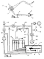
- et la figure 2 est le schéma synoptique d'un dispositif conforme à l'invention.
- FIG. 1, already mentioned, represents a typical endoscope
- and Figure 2 is a block diagram of a device according to the invention.
Comme dans le brevet cité plus haut, le dispositif de contrôle objet de la présente demande est composé d'une cuve 10 et comportant un capot 11 équipé d'un joint gonflable relié à une source d'air comprimé permettant d'assurer l'étanchéité de l'ensemble une fois le capot fermé.As in the patent cited above, the control device object of the present application consists of a
Il comporte en particulier une pompe de cyclage P1 qui brasse les solutions dans la cuve 10 dans laquelle est positionné l'endoscope 1. Cette pompe alimente au travers de deux clapet de non-retour C1, C2 une chambre hermétique 12 d'un volume connu préférablement au moins égal à une fois le volume maximal du plus volumineux des canaux d'un endoscope.It comprises in particular a cycling pump P1 which mixes the solutions in the
La cuve 10 est remplie au moyen d'électrovannes V1 et V4 reliées à un réseau d'eau de rinçage. Cette eau est filtrée à 0,2 microns. Les électrovannes sont reliées au circuit hydraulique en provenance de la pompe de cyclage entre les clapets C1 et C2.The
Un corps de chauffe permet de chauffer les sortions avant de les ré-injecter dans la cuve au moyen de deux types d'injecteurs 13, 17 permettant, pour les uns, de faire circuler les solutions autour de la partie externe de l'endoscope 1, pour les autres d'irriguer individuellement les canaux internes de l'appareil.A heating body makes it possible to heat the outlets before re-injecting them into the tank by means of two types of
Le fond de la cuve est raccordé à une pompe de vidange permettant de rejeter les solutions dans le réseau des eaux usées.The bottom of the tank is connected to a drain pump to reject the solutions in the wastewater network.
Les injecteurs non utilisés seront raccordés à des tubes de section interne inférieur à 5 mm avec une extrémité libre.Unused injectors will be connected to tubes of internal section less than 5 mm with a free end.
Le haut de la chambre hermétique 12 est raccordé à une électrovanne de liaison V2 dont l'aval est raccordé à la cuve 10 ou au capot 11 de celle-ci par l'intermédiaire d'un connecteur rapide 14 aisément accessible de l'extérieur de la machine par l'utilisateur et permettant rapidement et aisément d'injecter dans la chambre au moyen d'une seringue ou d'une pompe une solution, par exemple de prélèvement, qui puisse être recueillie après ouverture d'une ou de plusieurs électrovannes, à l'extrémité d'un ou plusieurs canaux de l'endoscope 1. Le bas de la chambre est raccordée aux électrovannes d'injection V3 qui chacune sont raccordées à un connecteur d'injecteur 13 spécifique dans la cuve lequel connecteur est lui même raccordé à une des entrées de canaux de l'endoscope 1. Une pompe d'injection P2 de liquide de séchage (alcool par exemple) est raccordée au travers d'un clapet de non retour C5 à la ligne en provenance du compresseur d'air entre les clapets C3 et C4.The top of the
L'électrovanne de liaison (V2) est raccordé à la cuve (10) ou au capot (11) de la cuve de façon à ce que l'air ainsi que les solutions de remplissage de la chambre hermétique (12) puissent revenir dans la cuve soit au dessus soit au dessous du niveau du liquide contenu dans ladite cuve.The connecting solenoid valve (V2) is connected to the tank (10) or the cover (11) of the tank so that the air and the filling solutions of the hermetic chamber (12) can return to the chamber. tank either above or below the level of the liquid contained in said tank.
La chambre hermétique 12 est également équipée d'un capteur de niveau bas N1 et d'un capteur de niveau haut N2.The sealed
Plusieurs chambres hermétiques de volumes différents peuvent être utilisées conjointement pour contrôler le débit de plusieurs endoscopes ou pour contrôler plus rapidement le débit dans des ensembles de canaux d'un même endoscope ayant des diamètres similaires.Several sealed chambers of different volumes can be used together to control the throughput of several endoscopes or to more quickly control the flow rate in sets of channels of the same endoscope having similar diameters.
Le système est équipé d'un compresseur 15 d'air filtré qui alimente la chambre hermétique 12 au travers d'une ligne comportant une soupape tarée à une pression donnée ou deux clapets de non retour C3, C4 entre lesquels est intercalé en dérivation un capteur de pression 16 qui permet de réguler la pression délivrée dans la chambre à des valeurs de consigne différentes.The system is equipped with a filtered air compressor which feeds the sealed
Les produits de nettoyage et de désinfection sont injectés sous forme concentrée dans la cuve 10 au moyen d'un dispositif de dosage. Ils y sont ensuite dilués par brassage à l'aide de la pompe de cyclage P1. Le cycle standard est généralement composé des séquences suivantes :
- Remplissage de la cuve
- Injection du produit de nettoyage
- Activation de la pompe de cyclage, nettoyage de la gaine externe de l'endoscope et irrigation des canaux de l'endoscope
- Vidange de la cuve
- Rinçage de la cuve et des canaux de l'endoscope en eau filtrée
- Remplissage de la cuve
- Injection du produit de désinfection
- Activation de la pompe de cyclage, désinfection de la gaine externe de l'endoscope et des canaux de l'endoscope
- Vidange de la cuve
- Rinçage de la cuve et des canaux de l'endoscope en eau filtrée
- Séchage des canaux
- Filling the tank
- Injecting the cleaning product
- Activation of the cycling pump, cleaning of the outer sheath of the endoscope and irrigation of the endoscope channels
- Draining the tank
- Rinsing the vat and the channels of the endoscope in filtered water
- Filling the tank
- Injection of the disinfection product
- Activation of the cycling pump, disinfection of the outer sheath of the endoscope and the channels of the endoscope
- Draining the tank
- Rinsing the vat and the channels of the endoscope in filtered water
- Drying of the channels
L'ensemble des composants électromécaniques sont pilotés par un automate avec microprocesseur qui en fonction de l'état de capteurs (niveau, pression, température) gère le cycle ainsi qu'un ensemble d'alarme d'interruption. Dans cette cuve peuvent être traités un ou plusieurs endoscopes.All the electromechanical components are controlled by a microprocessor controller which, depending on the sensor status (level, pressure, temperature), manages the cycle as well as a set of interrupt alarms. In this tank can be treated one or more endoscopes.
Les endoscopes 1 qui sont traités dans ce dispositif comportent une étiquette ou une puce qui permettent au moyen d'un lecteur de renseigner l'automate sur la marque de l'endoscope, son numéro de série ainsi que son type. L'automate a préalablement été programmé avec les données des fabricants d'endoscope concernant la longueur et le diamètre des canaux qui le constituent.The endoscopes 1 which are treated in this device comprise a label or a chip that allows, by means of a reader, to inform the automaton of the mark of the endoscope, its serial number and its type. The automaton was previously programmed with the data of the endoscope manufacturers concerning the length and the diameter of the channels which constitute it.
Pour le raccordement aux entrées de l'endoscope 1, des séparateurs sont préalablement mis en place dans la cage à piston 7 (figure 1) commune aux canaux air et eau de façon à séparer les flux. Ces séparateur sont usinés de façon à maintenir une infime communication entre les deux circuits permettant au désinfectant d'agir et de ne pas créer de zone morte non désinfectable. La mise en communication ne doit pas permettre une fuite supérieure à 30% du flux de chacun d'entre eux.For connection to the inputs of the endoscope 1, separators are previously placed in the piston cage 7 (Figure 1) common to the air and water channels so as to separate the flows. These separator are machined so as to maintain a tiny communication between the two circuits allowing the disinfectant to act and not to create a non-disinfectable dead zone. The communication must not allow a leak greater than 30% of the flow of each of them.
Pour certains des canaux de l'endoscope, notamment ceux de diamètre interne supérieur à 3 mm, le raccord de connexion à l'endoscope sera équipé d'un dispositif d'obturation qui n'autorise la circulation que si le raccord est correctement connecté sur l'entrée du canal.For some of the endoscope's channels, especially those with an internal diameter greater than 3 mm, the endoscope connection fitting will be equipped with a shutter that will only allow circulation if the fitting is properly connected to the endoscope. the entrance to the canal.
Chacune des entrées de l'endoscope est raccordée à un injecteur 13 distinct situé dans la cuve 10 et pouvant être identifié pour le raccordement d'au moins l'un des canaux suivant : canal à biopsie, canal d'aspiration, canal à biopsie auxiliaire ou du canal water-jet, canal air, canal eau, canal érecteur et canal eau auxiliaire.Each of the inputs of the endoscope is connected to a
Nous décrivons ci-dessous le principe du contrôle d'irrigation d'un des canaux avec les solutions en provenance de la cuve à l'aide du dispositif selon l'invention. Ce contrôle s'effectue selon les étapes suivantes :
- 1) L'état des capteurs de niveau N 1, N2 de la chambre hermétique 12 est contrôlé. Si la chambre n'est pas vide, le compresseur d'air 15 est activé en même temps que les électrovannes de canaux V3 de façon à vider la chambre.
- 2) Dès que les capteurs de niveau donnent l'indication adéquate, le compresseur 15 est activé jusqu'à ce qu'une valeur de consigne (Pa) enregistrée dans l'automate soit atteinte par le capteur de pression 16.
- 3) Un temps d'attente (TT) enregistré dans l'automate est observé. Si à la fin de ce temps la pression dans la chambre est toujours supérieure à (Pa-x), la séquence de contrôle est continuée. Dans le cas contraire, une alarme indique qu'une fuite est présente sur le circuit et que le test ne peut être mené à bien.
Cette opération permet de vérifier l'étanchéité de la chambre hermétique 12 avant tout remplissage, ainsi que de toutes les électrovannes de canaux V3 qui lui sont raccordées.
Les valeurs (TT),(Pa) et (x) sont déterminées en fonction des sections et des volumes des circuits et de la chambre hermétique 12 de façon à ce que le temps du diagnostic soit optimisé. - 4) L'électrovanne de liaison V2 est ouverte et la pompe de cyclage P1 est activée de façon à remplir la chambre hermétique 12 avec la solution en provenance de la cuve 10. Le temps (T1) pour atteindre le niveau haut (capteur N2) est chronométré et enregistré dans l'automate.
- 5) Dès que le capteur de niveau haut N2 indique que la chambre est pleine l'action est maintenue durant un temps d'attente égal à la moitié du temps de remplissage (T1/2) de façon à s'assurer que le circuit est saturé jusqu'à l'électrovanne de liaison V2.
- 6) Simultanément :
- la pompe de cyclage P1 est désactivée,
- l'électrovanne de liaison V2 est fermée.
- l'électrovanne V3 raccordée au canal à contrôler est ouverte.
- le compresseur d'air 15 est activé tant que la pression indiquée par le capteur de pression 16 n'excède pas la pression maximale (PM) autorisée pour l'irrigation du canal connecté à l'électrovanne de canal V3 ouverte.
- Un chronométrage est effectué jusqu'à ce que le capteur de niveau bas N1 indique que la chambre 12 est vide.
La valeur de la pression (PM) à appliquer dans la chambre doit permettre d'injecter le volume de solution emprisonné dans la chambre dans le temps le plus court sans cependant endommager les canaux de l'endoscope. Elle est comprise selon les canaux entre 400 et 3500 mbars. - 7) La connaissance du volume et du temps permet de déterminer le débit, de l'enregistrer dans une mémoire du microprocesseur et de le comparer à un débit de référence d'un endoscope de même type de ce même canal qui avait préalablement été enregistré dans l'automate en usine (lorsque l'endoscope est connu) ou lors de l'installation de la machine (si l'endoscope est un modèle peut répandu). Le temps de référence obtenu pourra avantageusement être enregistré dans l'automate ou dans une base de données externe connectée à l'automate.
Si le temps est supérieur à la valeur de référence majorée d'un coefficient (KB), il pourra être conclu que le canal est obstrué.
Si le temps est inférieur à la valeur de référence minorée d'un coefficient (KD), il pourra être conclu que le canal est déconnecté ou qu'une fuite est présente entre la sortie de l'électrovanne V3 et l'entrée du canal de l'endoscope.
Dans le cas où les débits sont dans la limite acceptable des valeurs préenregistrée, elles seront imprimés en fin de cycle sur le ticket de validation du cycle ou transféré sur un support de stockage. Dans le cas contraire le cycle sera interrompu et un message indiquera la cause ainsi que le canal à l'origine du défaut. - 8) Si l'endoscope 1 est pourvu de faisceau de canaux ayant une portion commune (canal biopsie et aspiration par exemple), la séquence ci-dessus sera réitérée mais en ouvrant en étape 5 l'ensembles des électrovannes raccordées à des canaux ayant des parties communes avec le canal à traiter, par exemple canal à biopsie et canal d'aspiration.
- 9) La connaissance du volume et du temps permet de déterminer le débit, de l'enregistrer dans une mémoire du microprocesseur et de le comparer à un débit de référence caractéristique de la vidange de la chambre hermétique 12 simultanément au travers de tous les canaux d'une même chambre.
Dans le cas où les débits sont dans la limite acceptable des valeurs préenregistrée, ils seront imprimés en fin de cycle sur le ticket de validation du cycle ou transféré sur un support de stockage. Dans le cas contraire le cycle sera interrompu et un message indiquera la cause ainsi que le canal à l'origine du défaut.
Si le temps est inférieur à la valeur de référence minorée d'un coefficient (KDG), il pourra être conclu que l'un des canaux du faisceau est déconnecté ou qu'une fuite est présente entre la sortie de l'électrovanne V3 et l'entrée du canal de l'endoscope. - 10) A la fin des phases de nettoyage et de désinfection et durant la vidange de la cuve 10, l'électrovanne de liaison V2 est ouverte ainsi que l'électrovanne de remplissage V1 en d'eau filtrée durant le temps nécessaire à rincer la chambre 12.
- 11) Puis les électrovannes V1, V2 sont fermées et le compresseur 15 est activé en même temps que les électrovannes de canaux V3 sont ouvertes et ce jusqu'à ce que le capteur de niveau N1 indique que la chambre 12 est vide. Les canaux ont ainsi été rincés avec de l'eau claire.
- 12) L e compresseur 15 est activé et les électrovannes de canaux V3 sont ouvertes durant le temps nécessaire à l'égouttage de l'endoscope 1.
- 1) The state of the level sensors N 1,
N 2 of thehermetic chamber 12 is controlled. If the chamber is not empty, theair compressor 15 is activated at the same time as the channel solenoid valves V3 so as to empty the chamber. - 2) As soon as the level sensors give the correct indication, the
compressor 15 is activated until a setpoint (Pa) stored in the PLC is reached by thepressure sensor 16. - 3) A waiting time (TT) stored in the PLC is observed. If at the end of this time the pressure in the chamber is still greater than (Pa-x), the control sequence is continued. If not, an alarm indicates that a leak is present on the circuit and the test can not be completed.
This operation makes it possible to check the tightness of thehermetic chamber 12 before any filling, as well as of all the solenoid valves of channels V3 connected thereto.
The values (TT), (Pa) and (x) are determined according to the sections and volumes of the circuits and the sealedchamber 12 so that the diagnosis time is optimized. - 4) The connecting solenoid valve V2 is opened and the cycling pump P1 is activated so as to fill the
hermetic chamber 12 with the solution coming from thetank 10. The time (T1) to reach the high level (sensor N2) is timed and stored in the automaton. - 5) As soon as the high level sensor N2 indicates that the chamber is full the action is maintained during a waiting time equal to half the filling time (T1 / 2) so as to ensure that the circuit is saturated up to the connecting solenoid valve V2.
- 6) Simultaneously:
- the cycling pump P1 is deactivated,
- the solenoid valve V2 connection is closed.
- the solenoid valve V3 connected to the channel to be checked is open.
- the
air compressor 15 is activated as long as the pressure indicated by thepressure sensor 16 does not exceed the maximum pressure (MP) allowed for irrigation of the channel connected to the open channel V3 solenoid valve. - Timing is performed until the low level sensor N1 indicates that the
chamber 12 is empty.
The value of the pressure (PM) to be applied in the chamber must allow to inject the volume of solution trapped in the chamber in the shortest time without however damaging the channels of the endoscope. It is included in the channels between 400 and 3500 mbar. - 7) The knowledge of the volume and the time makes it possible to determine the flow, to record it in a memory of the microprocessor and to compare it with a reference flow rate of an endoscope of the same type of this same channel which had previously been recorded in the automaton in the factory (when the endoscope is known) or during the installation of the machine (if the endoscope is a model can spread). The reference time obtained can advantageously be recorded in the PLC or in an external database connected to the PLC.
If the time is greater than the reference value plus a coefficient (KB), it can be concluded that the channel is obstructed.
If the time is less than the reference value minus a coefficient (KD), it can be concluded that the channel is disconnected or that a leak is present between the output of the solenoid valve V3 and the input of the channel of the endoscope.
In the case where the flow rates are within the acceptable limit of the prerecorded values, they will be printed at the end of the cycle on the validation ticket of the cycle or transferred to a storage medium. Otherwise the cycle will be interrupted and a message will indicate the cause as well as the channel causing the fault. - 8) If the endoscope 1 is provided with a bundle of channels having a common portion (biopsy channel and aspiration for example), the above sequence will be repeated but opening in
step 5 the sets of solenoid valves connected to channels having common parts with the channel to be treated, for example biopsy channel and suction channel. - 9) The knowledge of the volume and the time makes it possible to determine the flow rate, to record it in a memory of the microprocessor and to compare it with a reference flow rate characteristic of the emptying of the
hermetic chamber 12 simultaneously through all the channels of the same room.
In the case where the flows are within the acceptable limit of the pre-recorded values, they will be printed at the end of the cycle on the validation ticket of the cycle. or transferred to a storage medium. Otherwise the cycle will be interrupted and a message will indicate the cause as well as the channel causing the fault.
If the time is less than the reference value minus a coefficient (KDG), it can be concluded that one of the channels of the beam is disconnected or that a leak is present between the output of the solenoid valve V3 and the endoscope channel input. - 10) At the end of the cleaning and disinfection phases and during the emptying of the
tank 10, the connecting solenoid valve V2 is opened as well as the filling solenoid valve V1 in filtered water for the time necessary to rinse thechamber 12. - 11) Then the solenoid valves V1, V2 are closed and the
compressor 15 is activated at the same time as the solenoid valves V3 are open until the level sensor N1 indicates that thechamber 12 is empty. The channels were rinsed with clear water. - 12) The
compressor 15 is activated and the V3 channel solenoid valves are open for the time required to drain the endoscope 1.
Cette séquence de contrôle de débit dans les canaux est activée à une ou plusieurs reprises pour l'ensemble des canaux durant chaque phase du cycle avec la solution présente dans la cuve 10 soit :
- durant le remplissage de la cuve en eau
- durant le nettoyage
- durant le rinçage après nettoyage
- durant le second remplissage de la cuve 10
- durant la désinfection
- durant le rinçage post désinfection
- durant le troisième remplissage de la cuve 10
- durant le rinçage
- during filling of the tank with water
- during cleaning
- during rinsing after cleaning
- during the second filling of the
tank 10 - during disinfection
- during the rinse post disinfection
- during the third filling of the
tank 10 - during rinsing
Durant les périodes où le contrôle n'est pas activé, l'ensemble des électrovannes de canaux V3 sont ouvertes de façon à ce que le flux en provenance de l'électrovanne de remplissage V1 (irrigation en eau filtrée) ou de la pompe de cyclage P1 (irrigation en solution nettoyante ou désinfectante) passe librement dans la cuve 10 pour irriguer l'ensemble des canaux.During the periods when the control is not activated, all the solenoid valves V3 channels are open so that the flow from the filling solenoid valve V1 (filtered water irrigation) or the cycling pump P1 (irrigation cleaning solution or disinfectant) passes freely in the
Le dispositif permet également de contrôler un volume de liquide de séchage (alcool par exemple) injecté dans les canaux. Pour cela, l'électrovanne de liaison V2 ainsi que la pompe P2 de liquide de séchage sont activées jusqu'à ce que le niveau haut (capteur N2) de la chambre 12 soit atteint.The device also makes it possible to control a volume of drying liquid (alcohol for example) injected into the channels. For this, the connecting solenoid valve V2 and the pump P2 of drying liquid are activated until the high level (sensor N2) of the
Puis les électrovannes de canaux V3 sont ouvertes ainsi que le compresseur d'air 15 jusqu'à ce que le capteur de niveau bas N1 indique que la cuve 10 est vide, puis durant le temps nécessaire à l'égouttage ou à l'évaporation du liquide de séchage.Then the solenoid valves V3 channels are open and the
En fin de cycle, le capot 11 est ouvert et sans qu'il y ait besoin de déconnecter l'endoscope 1, des prélèvements peuvent être effectués.At the end of the cycle, the
Pour cela le raccord rapide 14 sera déconnecté et la ,partie en provenance de la chambre hermétique 12 est raccordée sur l'aval du corps d'une pompe péristaltique. Ce corps (tuyau en silicone) aura préalablement été stérilisé. L'amont du corps de la pompe est raccordé à un flacon de liquide de prélèvement. L'extrémité distale du tube d'exploration 3 de l'endoscope est insérée dans un bocal stérile de prélèvement.For this purpose the
L'opérateur peut alors sélectionner au moyen par exemple des touches de l'écran de saisie de l'automate le canal à prélever. Tant que la touche est activée, la pompe péristaltique et l'électrovanne V3 correspondant au canal sélectionné sont activées. Le liquide de prélèvement poussé par la pompe péristaltique ressort par l'extrémité du canal et est récupéré dans le bocal. Une fois que la quantité suffisante à été récupérée, la touche est désactivée et le prélèvement du canal suivant peut être effectué.The operator can then select by means for example keys from the input screen of the PLC the channel to be taken. As long as the key is activated, the peristaltic pump and solenoid valve V3 corresponding to the selected channel are activated. The sampling fluid pushed by the peristaltic pump emerges from the end of the channel and is recovered in the jar. Once the sufficient amount has been recovered, the key is disabled and the next channel can be taken.
Une séquence peut également être programmée qui automatiquement prélève un canal après l'autre.A sequence can also be programmed that automatically picks up one channel after another.
L'extrémité de l'endoscope est ensuite retirée du bocal de recueil, le raccord rapide 14 raccordé à la machine et un cycle est relancé de façon à rincer l'endoscope et le désinfecter à nouveau.The endoscope end is then removed from the collection jar, the
Les particularités apparaissant dans la description qui précède donnent à l'objet de l'invention un maximum d'effets utiles qui n'avaient pas été, à ce jour, obtenus par des dispositifs ou procédés similaires.The particularities appearing in the foregoing description give the object of the invention a maximum of useful effects which had not been obtained so far by similar devices or methods.
Claims (14)
- Device for measuring and monitoring the circulation of the fluids in channels and on the external parts of an endoscope, with the particular aim of checking and recording the flow of cleaning, disinfecting, rinsing and drying solutions which pass through each channel of endoscopes during their cleaning and disinfecting,
characterized by combining, on the one hand, a vessel (10) capable of receiving at least one endoscope (1), equipped with a sealing cover and associated with a pump (P1) circulating solutions for cleaning and disinfecting the outside of the endoscope, the aforementioned vessel being connected to a water intake together with a draining pump and equipped with internal injectors (13', 13) respectively used to circulate solutions around the external parts of endoscope (1) and irrigate the internal channels of the apparatus individually and, on the other, a system circulating appropriate fluids in each internal channel of endoscope (1) during each cleaning, disinfecting, rinsing and drying phase, thanks to at least one chamber (12) with hermetic connection on its lower part to injectors (13) of vessel (10) through a nozzle and solenoid valves (V3), an air compressor (15) allowing the pressure of the flux passing through the aforementioned channels to be increased, the assembly being arranged to allow a known volume of solution to circulate in the aforementioned channels, the system moreover allowing the control and recording of the flow in each channel at a given pressure. - Device according to claim 1 characterized in that that the top of hermetic chamber (12) is connected to vessel (10) or to cover (11) by a duct equipped with a solenoid connection valve (V2) arranged so that the air as well as the solutions for filling hermetic chamber (12) can return to vessel (10) either above or below the level of the liquid contained in the said vessel.
- Device according to claim 2 characterized in that the duct connecting hermetic chamber (12) to vessel (10) includes, downstream of connecting solenoid valve (V2), a quick connector (14) which is easily accessible to the user from the outside of the machine and allows quick and easy injection of a solution, for example for sampling, into the hermetic chamber (12) by means of a syringe or a pump, which can then be collected after opening one or several solenoid valves (V3) at the end of one or more channels of endoscope 1.
- Device according to any of the aforesaid claims, characterized in that it is equipped with a heater enabling the heating of the solutions before reinjecting them into vessel (10) by means of injectors (13', 13) or channels of endoscope (1).
- Device according to any of the aforesaid claims, characterized in that vessel (10) is supplied via two solenoid valves (V1, V4) connected on the one hand to a 0.2-micron filtered water supply and on the other to the hydraulic circuit from the circulating pump (P1).
- Device according to any of the aforesaid claims, characterized in that hermetic chamber (12) can be fed by circulating pump (P1) thanks to two non-return valves (C1, C2).
- Device according to any of the aforesaid claims, characterized in that certain connections between injectors (13) and endoscope (1) are equipped with a plugging device which authorizes the circulation of fluid only if the connection is connected correctly onto the intake to the corresponding channel.
- Device according to any of the aforesaid claims, characterized in that it includes a pump (P2) for injecting drying liquid connected through a non-return valve (C5) to the nozzle from air compressor (15) between two valves C3 and C4.
- Device according to any of the aforesaid claims, characterized in that hermetic chamber (12) is equipped with a low level detector (N1) and with a high level detector (N2) for controlling its filling and draining.
- Device according to any of the aforesaid claims, characterized in that it is equipped with a reader able to decode a label or a chip installed on endoscopes (1) and on which are recorded its make, its production number and its type.
- Method of measuring and controlling the circulation of the fluids in the channels and on the external parts of an endoscope using the device according to claims 1 to 10,
characterized in that endoscope (1) is arranged in vessel (10) of a cleaning and disinfecting apparatus operated by a programmable logic controller, each channel entry of which is connected via injectors (13) of the aforesaid vessel and solenoid valves connected by a nozzle at the bottom of a hermetic chamber (12) of known volume equipped with two level detectors (N1, N2) for controlling its filling and its draining, the upper part of which is connected to a compressor (15) of filtered air controlled by a pressure sensor (16) and to a connecting solenoid valve (V2) allowing the air to evacuate when filling the aforesaid chamber, and which can be used to measure and record the time required to pass from the high level to the low level when the air is injected into hermetic chamber (12) at a given pressure and one or more solenoid valves (V3) connected to a channel is/are open. - Method according to claim 11, characterized in that the cleaning and disinfecting cycle consists of the following sequences:- Filling of vessel (10),- Injection of the cleaning product.- Activation of circulating pump (P1), cleaning of the external sheath of endoscope (1) and irrigation of the endoscope channels.- Draining of the vessel.- Rinsing of the vessel and the endoscope channels with filtered water.- Filling of the vessel.- Injection of the disinfecting product.- Activation of circulation pump (P1), disinfecting of the external sheath of the endoscope and the endoscope channels.- Draining of the vessel.- Rinsing of the vessel and the endoscope channels with filtered water.- Drying of the channels.
- Method according to any of claims 11 and 12, characterized in that the inspection stages include the following operations in succession:- Draining of hermetic chamber (12) down to the low level.- Checking the airtightness of the aforesaid chamber as well as each of the solenoid valves of the channels (V3) and the disks valve connected to it.- Filling of the chamber up to high level (N2) and checking the filling time.- Draining of the hermetic chamber and noting the time to reach the low level.
- Method according to any of claims 11 to 13, characterized in that the check is repeated on same endoscope channel (1) several time and is recorded, the average of the measurements being compared to a reference time.
Applications Claiming Priority (3)
| Application Number | Priority Date | Filing Date | Title |
|---|---|---|---|
| FR0203439A FR2837392B1 (en) | 2002-03-20 | 2002-03-20 | METHOD AND DEVICE FOR MEASURING AND CONTROLLING THE FLOW CIRCULATION IN ENDOSCOPE CHANNELS |
| FR0203439 | 2002-03-20 | ||
| PCT/FR2003/000479 WO2003077960A1 (en) | 2002-03-20 | 2003-02-14 | Method and device for measuring and controlling the circulation of fluids in endoscope channels |
Publications (2)
| Publication Number | Publication Date |
|---|---|
| EP1485134A1 EP1485134A1 (en) | 2004-12-15 |
| EP1485134B1 true EP1485134B1 (en) | 2006-06-21 |
Family
ID=27799100
Family Applications (1)
| Application Number | Title | Priority Date | Filing Date |
|---|---|---|---|
| EP20030718874 Expired - Lifetime EP1485134B1 (en) | 2002-03-20 | 2003-02-14 | Method and device for measuring and controlling the circulation of fluids in endoscope channels |
Country Status (9)
| Country | Link |
|---|---|
| US (1) | US7708938B2 (en) |
| EP (1) | EP1485134B1 (en) |
| AT (1) | ATE330641T1 (en) |
| AU (1) | AU2003222912B2 (en) |
| CA (1) | CA2478848C (en) |
| DE (1) | DE60306345T2 (en) |
| ES (1) | ES2266807T3 (en) |
| FR (1) | FR2837392B1 (en) |
| WO (1) | WO2003077960A1 (en) |
Families Citing this family (24)
| Publication number | Priority date | Publication date | Assignee | Title |
|---|---|---|---|---|
| DE10334562B4 (en) * | 2003-07-29 | 2005-06-09 | Erbe Elektromedizin Gmbh | Surgical instrument |
| DE10352198B4 (en) * | 2003-11-05 | 2005-08-04 | Bht Hygienetechnik Gmbh | Method for analyzing channels, in particular endoscope channels, and device for carrying out the method |
| ITRM20050368A1 (en) * | 2005-07-11 | 2007-01-12 | Ims S R L | COLD STERILIZER. |
| US7340943B2 (en) * | 2005-09-30 | 2008-03-11 | Ethicon, Inc. | Method of detecting connection of test port on an endoscope |
| US7686761B2 (en) * | 2005-10-28 | 2010-03-30 | Ethicon, Inc. | Method of detecting proper connection of an endoscope to an endoscope processor |
| US7901349B2 (en) * | 2005-11-02 | 2011-03-08 | Minntech Corporation | Endoscope reprocessor connectivity apparatus and method |
| WO2008085209A1 (en) * | 2006-09-08 | 2008-07-17 | Lahaye Leaon C | Apparatus and method for cleaning lumens of medical devices and lines |
| JP5188800B2 (en) * | 2007-12-21 | 2013-04-24 | オリンパスメディカルシステムズ株式会社 | Endoscope cleaning / disinfecting apparatus and water leakage detection method using the endoscope cleaning / disinfecting apparatus |
| DE102008063273A1 (en) | 2008-12-29 | 2010-07-01 | Olympus Winter & Ibe Gmbh | Test device for endoscope washing machine |
| US8673212B2 (en) * | 2010-05-28 | 2014-03-18 | Steris Corporation | Apparatus to decontaminate equipment containing internal channels |
| DE102012109463A1 (en) * | 2012-10-05 | 2014-06-12 | Miele & Cie. Kg | Cleaning device for English channels, pipes, pipes or the like |
| DE102012020934B4 (en) | 2012-10-25 | 2014-08-21 | SciCan GmbH | Method for cleaning and disinfecting endoscopes |
| US9161680B2 (en) | 2013-11-26 | 2015-10-20 | Bracco Diagnostics Inc. | Disposable air/water valve for an endoscopic device |
| DE102015203429A1 (en) * | 2015-02-26 | 2016-09-01 | Olympus Winter & Ibe Gmbh | Fluid distributor for a treatment device for surgical instruments |
| CN105641725A (en) * | 2015-08-17 | 2016-06-08 | 李学军 | Medical lab medical waste liquid automatic disinfecting device |
| CN108601515B (en) | 2016-07-29 | 2020-07-28 | 奥林巴斯株式会社 | Endoscope regeneration processor |
| EP3618726A1 (en) | 2017-05-02 | 2020-03-11 | Ambu A/S | An endoscope |
| EP3618725A1 (en) | 2017-05-02 | 2020-03-11 | Ambu A/S | A set of sampling parts |
| CN107470226A (en) * | 2017-08-29 | 2017-12-15 | 章麒 | A kind of medicine equipment circulates perfusion cleaning device control system |
| DE102017122434A1 (en) * | 2017-09-27 | 2019-03-28 | Olympus Winter & Ibe Gmbh | Method for processing an endoscope having at least one channel in a preparation device |
| EP3530298B1 (en) | 2018-02-21 | 2023-09-06 | Ambu A/S | A medical sampling device |
| CN108746046A (en) * | 2018-07-07 | 2018-11-06 | 广州市三妙医药科技有限公司 | A kind of pipe-line system and its working method of endoscope cleaner |
| CN111513665B (en) * | 2020-04-28 | 2023-08-29 | 诺信医学科技(山东)有限公司 | Gastroenterology scope belt cleaning device |
| WO2023177567A1 (en) * | 2022-03-14 | 2023-09-21 | Conmed Corporation | Surgical gas delivery system for gas sealed insufflation and recirculation with pneumatically powered blocking valves |
Family Cites Families (7)
| Publication number | Priority date | Publication date | Assignee | Title |
|---|---|---|---|---|
| GB9211499D0 (en) * | 1992-05-30 | 1992-07-15 | Univ Salford Business Services | Endoscope washing and disinfection |
| EP0603563A1 (en) * | 1992-12-04 | 1994-06-29 | F. Gehrig + Co. Ag | Method and apparatus for testing and cleaning endoscopes |
| FR2705896B3 (en) * | 1993-06-03 | 1995-08-18 | Mariotti Bernard | Decontamination, disinfection and drying device for sealed endoscopes. |
| DE4440363C2 (en) * | 1994-11-11 | 1997-10-02 | Netzsch Newamatic Gmbh | Procedure for testing and cleaning instruments for minimally invasive surgery or minimally invasive examination of body cavities |
| US20020064479A1 (en) | 1998-03-26 | 2002-05-30 | Nobuyuki Nakanishi | Apparatus for washing and disinfecting-sterilizing endoscope |
| FR2803755B1 (en) * | 2000-01-19 | 2002-03-08 | Bernard Mariotti | CLEANING AND DISINFECTING DEVICE FOR MEDICAL ENDOSCOPES |
| JP4804614B2 (en) * | 2000-08-29 | 2011-11-02 | オリンパス株式会社 | Endoscope washing device |
-
2002
- 2002-03-20 FR FR0203439A patent/FR2837392B1/en not_active Expired - Fee Related
-
2003
- 2003-02-14 ES ES03718874T patent/ES2266807T3/en not_active Expired - Lifetime
- 2003-02-14 EP EP20030718874 patent/EP1485134B1/en not_active Expired - Lifetime
- 2003-02-14 AU AU2003222912A patent/AU2003222912B2/en not_active Expired
- 2003-02-14 CA CA 2478848 patent/CA2478848C/en not_active Expired - Lifetime
- 2003-02-14 DE DE2003606345 patent/DE60306345T2/en not_active Expired - Lifetime
- 2003-02-14 US US10/506,682 patent/US7708938B2/en active Active
- 2003-02-14 WO PCT/FR2003/000479 patent/WO2003077960A1/en not_active Application Discontinuation
- 2003-02-14 AT AT03718874T patent/ATE330641T1/en not_active IP Right Cessation
Also Published As
| Publication number | Publication date |
|---|---|
| EP1485134A1 (en) | 2004-12-15 |
| CA2478848C (en) | 2011-04-26 |
| DE60306345T2 (en) | 2007-06-21 |
| FR2837392A1 (en) | 2003-09-26 |
| FR2837392B1 (en) | 2004-07-02 |
| WO2003077960A1 (en) | 2003-09-25 |
| AU2003222912B2 (en) | 2008-05-22 |
| AU2003222912A1 (en) | 2003-09-29 |
| US20050079094A1 (en) | 2005-04-14 |
| CA2478848A1 (en) | 2003-09-25 |
| ATE330641T1 (en) | 2006-07-15 |
| ES2266807T3 (en) | 2007-03-01 |
| US7708938B2 (en) | 2010-05-04 |
| DE60306345D1 (en) | 2006-08-03 |
Similar Documents
| Publication | Publication Date | Title |
|---|---|---|
| EP1485134B1 (en) | Method and device for measuring and controlling the circulation of fluids in endoscope channels | |
| JP4969951B2 (en) | Solution testing of automatic endoscope cleaning equipment | |
| US11771791B2 (en) | Apparatus and method to repeatedly fill and purge channels of endoscope | |
| EP1156840B1 (en) | Tubing for extracorporal purification of the blood and use thereof | |
| EP2291109B1 (en) | System and method for storing a medical endoscope | |
| US11317793B2 (en) | Apparatus and method to asynchronously fill and purge channels of endoscope simultaneously | |
| JP2004202247A (en) | Method for detecting proper binding of fixture to channel of endoscope | |
| BR102017010269A2 (en) | apparatus and method for identifying the type of endoscope and providing adapted reprocessing | |
| JP2006280944A (en) | Connection integrity test of automatic endoscope regenerator by liquid suction | |
| EP3453311B1 (en) | Apparatus and method for delivery of concentrated disinfectant or sterilant into the lumen of a medical instrument | |
| FR2803755A1 (en) | Cleaning device for medical endoscopes has an arrangement of inner and outer compartments within a hermetically sealed vat that are supplied with cleaning fluid so that flows around the endoscope providing efficient cleaning | |
| JP7434478B2 (en) | Apparatus and method for asynchronously and simultaneously filling and purging endoscope channels | |
| US20240049957A1 (en) | System And Method For Mirroring Conditions Associated With A Medical Device Reprocessor | |
| JP2018033964A (en) | Multi port cap for reagent container | |
| WO2020245658A2 (en) | System and method for drying channels of medical instrument during cleaning |
Legal Events
| Date | Code | Title | Description |
|---|---|---|---|
| PUAI | Public reference made under article 153(3) epc to a published international application that has entered the european phase |
Free format text: ORIGINAL CODE: 0009012 |
|
| 17P | Request for examination filed |
Effective date: 20040920 |
|
| AK | Designated contracting states |
Kind code of ref document: A1 Designated state(s): AT BE BG CH CY CZ DE DK EE ES FI FR GB GR HU IE IT LI LU MC NL PT SE SI SK TR |
|
| 17Q | First examination report despatched |
Effective date: 20050222 |
|
| GRAP | Despatch of communication of intention to grant a patent |
Free format text: ORIGINAL CODE: EPIDOSNIGR1 |
|
| GRAS | Grant fee paid |
Free format text: ORIGINAL CODE: EPIDOSNIGR3 |
|
| GRAA | (expected) grant |
Free format text: ORIGINAL CODE: 0009210 |
|
| AK | Designated contracting states |
Kind code of ref document: B1 Designated state(s): AT BE BG CH CY CZ DE DK EE ES FI FR GB GR HU IE IT LI LU MC NL PT SE SI SK TR |
|
| PG25 | Lapsed in a contracting state [announced via postgrant information from national office to epo] |
Ref country code: AT Free format text: LAPSE BECAUSE OF FAILURE TO SUBMIT A TRANSLATION OF THE DESCRIPTION OR TO PAY THE FEE WITHIN THE PRESCRIBED TIME-LIMIT Effective date: 20060621 Ref country code: IE Free format text: LAPSE BECAUSE OF FAILURE TO SUBMIT A TRANSLATION OF THE DESCRIPTION OR TO PAY THE FEE WITHIN THE PRESCRIBED TIME-LIMIT Effective date: 20060621 Ref country code: IT Free format text: LAPSE BECAUSE OF FAILURE TO SUBMIT A TRANSLATION OF THE DESCRIPTION OR TO PAY THE FEE WITHIN THE PRESCRIBED TIME-LIMIT;WARNING: LAPSES OF ITALIAN PATENTS WITH EFFECTIVE DATE BEFORE 2007 MAY HAVE OCCURRED AT ANY TIME BEFORE 2007. THE CORRECT EFFECTIVE DATE MAY BE DIFFERENT FROM THE ONE RECORDED. Effective date: 20060621 Ref country code: NL Free format text: LAPSE BECAUSE OF FAILURE TO SUBMIT A TRANSLATION OF THE DESCRIPTION OR TO PAY THE FEE WITHIN THE PRESCRIBED TIME-LIMIT Effective date: 20060621 Ref country code: FI Free format text: LAPSE BECAUSE OF FAILURE TO SUBMIT A TRANSLATION OF THE DESCRIPTION OR TO PAY THE FEE WITHIN THE PRESCRIBED TIME-LIMIT Effective date: 20060621 Ref country code: SI Free format text: LAPSE BECAUSE OF FAILURE TO SUBMIT A TRANSLATION OF THE DESCRIPTION OR TO PAY THE FEE WITHIN THE PRESCRIBED TIME-LIMIT Effective date: 20060621 Ref country code: CZ Free format text: LAPSE BECAUSE OF FAILURE TO SUBMIT A TRANSLATION OF THE DESCRIPTION OR TO PAY THE FEE WITHIN THE PRESCRIBED TIME-LIMIT Effective date: 20060621 Ref country code: SK Free format text: LAPSE BECAUSE OF FAILURE TO SUBMIT A TRANSLATION OF THE DESCRIPTION OR TO PAY THE FEE WITHIN THE PRESCRIBED TIME-LIMIT Effective date: 20060621 |
|
| REG | Reference to a national code |
Ref country code: GB Ref legal event code: FG4D Free format text: NOT ENGLISH |
|
| REG | Reference to a national code |
Ref country code: CH Ref legal event code: EP |
|
| REG | Reference to a national code |
Ref country code: IE Ref legal event code: FG4D Free format text: LANGUAGE OF EP DOCUMENT: FRENCH |
|
| REF | Corresponds to: |
Ref document number: 60306345 Country of ref document: DE Date of ref document: 20060803 Kind code of ref document: P |
|
| PG25 | Lapsed in a contracting state [announced via postgrant information from national office to epo] |
Ref country code: DK Free format text: LAPSE BECAUSE OF FAILURE TO SUBMIT A TRANSLATION OF THE DESCRIPTION OR TO PAY THE FEE WITHIN THE PRESCRIBED TIME-LIMIT Effective date: 20060921 Ref country code: SE Free format text: LAPSE BECAUSE OF FAILURE TO SUBMIT A TRANSLATION OF THE DESCRIPTION OR TO PAY THE FEE WITHIN THE PRESCRIBED TIME-LIMIT Effective date: 20060921 |
|
| GBT | Gb: translation of ep patent filed (gb section 77(6)(a)/1977) |
Effective date: 20060928 |
|
| PG25 | Lapsed in a contracting state [announced via postgrant information from national office to epo] |
Ref country code: PT Free format text: LAPSE BECAUSE OF FAILURE TO SUBMIT A TRANSLATION OF THE DESCRIPTION OR TO PAY THE FEE WITHIN THE PRESCRIBED TIME-LIMIT Effective date: 20061121 |
|
| NLV1 | Nl: lapsed or annulled due to failure to fulfill the requirements of art. 29p and 29m of the patents act | ||
| REG | Reference to a national code |
Ref country code: IE Ref legal event code: FD4D |
|
| PG25 | Lapsed in a contracting state [announced via postgrant information from national office to epo] |
Ref country code: CH Free format text: LAPSE BECAUSE OF NON-PAYMENT OF DUE FEES Effective date: 20070228 Ref country code: MC Free format text: LAPSE BECAUSE OF NON-PAYMENT OF DUE FEES Effective date: 20070228 Ref country code: LI Free format text: LAPSE BECAUSE OF NON-PAYMENT OF DUE FEES Effective date: 20070228 |
|
| REG | Reference to a national code |
Ref country code: ES Ref legal event code: FG2A Ref document number: 2266807 Country of ref document: ES Kind code of ref document: T3 |
|
| PLBE | No opposition filed within time limit |
Free format text: ORIGINAL CODE: 0009261 |
|
| STAA | Information on the status of an ep patent application or granted ep patent |
Free format text: STATUS: NO OPPOSITION FILED WITHIN TIME LIMIT |
|
| 26N | No opposition filed |
Effective date: 20070322 |
|
| REG | Reference to a national code |
Ref country code: CH Ref legal event code: PL |
|
| PG25 | Lapsed in a contracting state [announced via postgrant information from national office to epo] |
Ref country code: GR Free format text: LAPSE BECAUSE OF FAILURE TO SUBMIT A TRANSLATION OF THE DESCRIPTION OR TO PAY THE FEE WITHIN THE PRESCRIBED TIME-LIMIT Effective date: 20060922 |
|
| PG25 | Lapsed in a contracting state [announced via postgrant information from national office to epo] |
Ref country code: BG Free format text: LAPSE BECAUSE OF FAILURE TO SUBMIT A TRANSLATION OF THE DESCRIPTION OR TO PAY THE FEE WITHIN THE PRESCRIBED TIME-LIMIT Effective date: 20060921 |
|
| PG25 | Lapsed in a contracting state [announced via postgrant information from national office to epo] |
Ref country code: EE Free format text: LAPSE BECAUSE OF FAILURE TO SUBMIT A TRANSLATION OF THE DESCRIPTION OR TO PAY THE FEE WITHIN THE PRESCRIBED TIME-LIMIT Effective date: 20060621 |
|
| PG25 | Lapsed in a contracting state [announced via postgrant information from national office to epo] |
Ref country code: CY Free format text: LAPSE BECAUSE OF FAILURE TO SUBMIT A TRANSLATION OF THE DESCRIPTION OR TO PAY THE FEE WITHIN THE PRESCRIBED TIME-LIMIT Effective date: 20060621 Ref country code: LU Free format text: LAPSE BECAUSE OF NON-PAYMENT OF DUE FEES Effective date: 20070214 |
|
| PG25 | Lapsed in a contracting state [announced via postgrant information from national office to epo] |
Ref country code: TR Free format text: LAPSE BECAUSE OF FAILURE TO SUBMIT A TRANSLATION OF THE DESCRIPTION OR TO PAY THE FEE WITHIN THE PRESCRIBED TIME-LIMIT Effective date: 20060621 Ref country code: HU Free format text: LAPSE BECAUSE OF FAILURE TO SUBMIT A TRANSLATION OF THE DESCRIPTION OR TO PAY THE FEE WITHIN THE PRESCRIBED TIME-LIMIT Effective date: 20061222 |
|
| REG | Reference to a national code |
Ref country code: GB Ref legal event code: 732E Free format text: REGISTERED BETWEEN 20140605 AND 20140611 |
|
| REG | Reference to a national code |
Ref country code: ES Ref legal event code: PC2A Owner name: SOLUSCOPE SAS Effective date: 20140702 |
|
| REG | Reference to a national code |
Ref country code: GB Ref legal event code: 732E Free format text: REGISTERED BETWEEN 20140619 AND 20140625 |
|
| REG | Reference to a national code |
Ref country code: DE Ref legal event code: R082 Ref document number: 60306345 Country of ref document: DE Representative=s name: PUSCHMANN BORCHERT BARDEHLE PATENTANWAELTE PAR, DE |
|
| REG | Reference to a national code |
Ref country code: FR Ref legal event code: TP Owner name: SOLUSCOPE, FR Effective date: 20140527 |
|
| REG | Reference to a national code |
Ref country code: DE Ref legal event code: R081 Ref document number: 60306345 Country of ref document: DE Owner name: SOLUSCOPE SAS, FR Free format text: FORMER OWNER: BERNARD MARIOTTI,FREDERIC DRAY, , FR Effective date: 20140723 Ref country code: DE Ref legal event code: R082 Ref document number: 60306345 Country of ref document: DE Representative=s name: PUSCHMANN BORCHERT BARDEHLE PATENTANWAELTE PAR, DE Effective date: 20140723 Ref country code: DE Ref legal event code: R081 Ref document number: 60306345 Country of ref document: DE Owner name: SOLUSCOPE SAS, FR Free format text: FORMER OWNERS: MARIOTTI, BERNARD, MARSEILLE, FR; DRAY, FREDERIC, MARSEILLE, FR Effective date: 20140723 |
|
| REG | Reference to a national code |
Ref country code: FR Ref legal event code: PLFP Year of fee payment: 14 |
|
| REG | Reference to a national code |
Ref country code: FR Ref legal event code: PLFP Year of fee payment: 15 |
|
| REG | Reference to a national code |
Ref country code: FR Ref legal event code: PLFP Year of fee payment: 16 |
|
| PGFP | Annual fee paid to national office [announced via postgrant information from national office to epo] |
Ref country code: GB Payment date: 20211223 Year of fee payment: 20 Ref country code: FR Payment date: 20211217 Year of fee payment: 20 |
|
| PGFP | Annual fee paid to national office [announced via postgrant information from national office to epo] |
Ref country code: DE Payment date: 20211222 Year of fee payment: 20 |
|
| PGFP | Annual fee paid to national office [announced via postgrant information from national office to epo] |
Ref country code: IT Payment date: 20220111 Year of fee payment: 20 Ref country code: ES Payment date: 20220303 Year of fee payment: 20 Ref country code: BE Payment date: 20220118 Year of fee payment: 20 |
|
| REG | Reference to a national code |
Ref country code: DE Ref legal event code: R071 Ref document number: 60306345 Country of ref document: DE |
|
| REG | Reference to a national code |
Ref country code: BE Ref legal event code: MK Effective date: 20230214 |
|
| REG | Reference to a national code |
Ref country code: GB Ref legal event code: PE20 Expiry date: 20230213 |
|
| REG | Reference to a national code |
Ref country code: ES Ref legal event code: FD2A Effective date: 20230426 |
|
| PG25 | Lapsed in a contracting state [announced via postgrant information from national office to epo] |
Ref country code: GB Free format text: LAPSE BECAUSE OF EXPIRATION OF PROTECTION Effective date: 20230213 |
|
| PG25 | Lapsed in a contracting state [announced via postgrant information from national office to epo] |
Ref country code: ES Free format text: LAPSE BECAUSE OF EXPIRATION OF PROTECTION Effective date: 20230215 |