BACKGROUND OF THE INVENTION
This invention was made with government support under contract N00014-95-C-0023
awarded by Navy/DARPA. The government has certain rights in this invention.
Field of the Invention
The present invention relates to separators between adjacent electrochemical cells. More
particularly, the invention relates to lightweight bipolar plates and methods for their construction.
Background of the Invention
Electrochemical cells utilizing a proton exchange membrane (PEM) can be configured
in cell stacks having bipolar separator plates between adjacent cells. These bipolar separator
plates are typically made from a variety of metals, such as titanium and stainless steel, and non-metallic
conductors, such as graphitic carbon. Bipolar separator plates can be fabricated by
machining fluid flow fields into a solid sheet of the material. The flow fields are made up of a
series of channels or grooves that allow passage of gases and liquids.
Figure 1 is a face view of a prior art bipolar separator plate 10 made from a solid sheet
of a conducting material. The central portion of the plate has a flow field 12 machined into its
surface. The flow field may direct fluid flow in many patterns, but is illustrated here as parallel
serpentine channels. Around the perimeter of the flow field 12, the plate provides a plurality of
bolt holes 14 for assembling and securing a cell stack, various manifolds 16 for communicating
fluids in and out of the stack, and a flat surface 18 that allows the plate to be sealed with adjacent
components of the cell stack.
In addition to providing a fluid flow field, a bipolar separator plate for use in
electrochemical cells must collect electrons liberated at one electrode, conduct the electrons
through the plate, and deliver electrons to the face of another electrode on the opposing side of
the plate. The prior art bipolar separator plate collects and delivers electrons from electrodes of
opposing cells through the ridges 20 remaining between the channels 22 in the flow field 12.
Figure 2 is a schematic view of a proton exchange membrane (PEM) electrochemical cell
30 configured as a hydrogen-air fuel cell. This stack comprises two identical fuel cells 32 having
a cathode 34, a PEM 36 and an anode 38. Flow fields 40 (shown schematically for clarity) are
provided on either side of the bipolar separator plate 42, as well as on the internal faces of the
endplates 44. Electrons liberated at the anode 38 provide current flow to the cathode 34 of a cell
on the other side of the plate 42 and, ultimately, through an external circuit 46. Electrons are
then combined with protons and oxygen at the cathode 34 to form water. The electrical potential
of the fuel cell 30 is increased by adding more cells 32 to the stack.
Weight is a characteristic of electrochemical cells generally, and fuel cells in particular,
that limits their use. Therefore, significant efforts have been directed at providing lightweight
components for electrochemical cells. Even so, there remains a need for a lightweight bipolar
separator plate. It would be desirable if the lightweight bipolar separator plate could also be
made thinner and support higher current densities. It would be further desirable if the structure
of the bipolar separator plate allowed the introduction of other specific properties, such as water
permeability and reactant gas impermeability.
Summary of the Invention
The present invention provides a separator for electrochemical cells comprising a gas
barrier having an electrically conducting pathway extending therethrough and a porous,
electrically conducting member in electrical contact with each side of the electrically conducting
pathway, the member selected from the group consisting of expanded metal mesh, metal foam,
conducting polymer foam, porous conductive carbon material and combinations thereof. The
electrically conducting pathway through the gas barrier may be formed from a second porous,
electrically conducting member selected from the group consisting of expanded metal mesh,
metal foam, conducting polymer foam, porous conductive carbon material and combinations
thereof. The gas barrier may be comprised of a metal sheet or a polymer filled porous,
electrically conducting member.
In another aspect of the invention, a separator for electrochemical cells is provided
comprising a porous, electrically conducting sheet selected from the group consisting of
expanded metal mesh, metal foam, conducting polymer foam, porous conductive carbon material
and combinations thereof and a gas impermeable material, such as a polymer or metal, disposed
within a portion of the sheet to form a gas barrier. The gas impermeable polymers are selected
from the group consisting of water permeable polymers, thermoplastic polymers, reactively cured
polymers, and combinations thereof.
In yet another aspect of the invention, a separator for electrochemical cells is provided.
comprising two porous, electrically conducting sheets selected from the group consisting of
expanded metal mesh, metal foam, conducting polymer foam, porous conductive carbon material
and combinations thereof and an electrically conducting gas barrier disposed in electrical contact
between the sheets.
Brief Description of the Drawings
So that the manner in which the above recited features, advantages and objects of the
present invention are attained and can be understood in detail, a more particular description of
the invention, briefly summarized above, may be had by reference to the embodiments thereof
which are illustrated in the appended drawings.
It is to be noted, however, that the appended drawings illustrate only typical embodiments
of this invention and are therefore not to be considered limiting of its scope, for the invention
may admit to other equally effective embodiments.
Detailed Description of the Invention
The present invention provides improved, lightweight bipolar separator plates and
methods for their manufacture. The weight of the separator is minimized by reducing the amount
of dense materials (solid metal or graphite) that are used and replacing them with lighter
materials. Solid materials are used only where dictated to provide structural strength, such as the
outer frame of the bipolar plate where a gas seal must be achieved. Other parts of the plate, such
as the flow field, are constructed from electrically conductive materials having a lower density,
such as expanded metal mesh, or foamed metal. While these lower density materials are
electrically conductive, they are not gas tight and, if used alone, would not provide a sufficient
gas barrier. However, in accordance with the present invention a gas barrier can be used in
conjunction with these low density materials.
In one aspect of the invention, a bipolar separator plate is provided with a thin.
electrically conductive sheet forming a gas tight barrier. Conductive sheets, such as titanium,
provide much thinner gas barriers than can be achieved by machining a solid metal plate to leave
a flow field and a barrier structure. Sheets of low density, electrically conductive material are
placed in electrical contact on both sides of the barrier, so that the low density material serves
as the flow field.
In another aspect of the invention, a bipolar separator plate is provided by forming a
polymer barrier inside a sheet of low density metal. The polymer is disposed into the pores of
the low density metal to form a gas barrier. It is preferred that the polymer fill only a region of
pores, leaving another region to serve as a flow field. Polymers with special properties, such as
water permeability, may be used for the gas barrier to provide the separator plates with additional
advantages.
In yet another aspect of the invention, the porous flow fields may be provided with
grooves or channels to improve the distribution of fluid and reduce the pressure drop across the
flow field. While the grooves may take on a number of patterns, the preferred groove pattern is
interdigitated. The interdigitated pattern includes finger-like channels that freely communicate
fluid from the inlet manifold into the flow field, yet requires the fluid to pass through at least a
portion of the porous flow field before communicating with adjacent finger-like channels
communicating with the outlet manifold.
In a further aspect of the invention, a bipolar separator plate is provided with a frame
having channels formed therein for fluid communication with the edges of the flow field. The
frame may be made of a solid material, such as metal, a polymer material or combinations
thereof. The direction of fluid flow in the anode and cathode flow fields may be either parallel
or cross flow, as is determined by the fluid channels and manifolding in the frame. It should be
recognized that within a given cell stack, the manifolding must be consistent throughout.
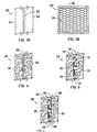
Now referring to Figure 3A and 3B, a cross-sectional view of a bipolar plate 50 is shown
constructed with a thin, metal sheet 52 having a flow field 54 made of expanded metal mesh spot
welded to both sides thereof. The metal sheet 52 forms an impermeable gas barrier across the
entire face of the plate 50 and the expanded metal mesh forms the fluid flow field 54. The sheet
and mesh may be made from titanium SS, Al, Mg, or alloys thereof, most preferably titanium
metal. It is most preferred that the titanium bipolar plate 50 be plated with a noble metal, gold,
or other materials after welding to prevent oxidation and corrosion of the metal in the fuel cell
environment.
Now referring to Figure 4, a cross-sectional view of an all metal bipolar plate 60 is shown
constructed with a thin, metal sheet 62 having metal foam flow fields 66. This bipolar plate
features a thin (≤0.006") barrier sheet 62, preferably made from a solid titanium sheet, with metal
foam (about 1/8 inch thick) welded to both sides thereof. The metal sheet 62 again forms the gas
barrier and the metal foam 66 forms the fluid flow fields. Metals that can be prepared as a solid
foam in accordance with the present invention include copper, aluminum, nickel, titanium, silver,
and stainless steel, with the preferred metals being nickel and stainless steel. The density of the
metal foam used in the sheet 66 can be up to about 50 percent metal by volume, but the preferred
density of the foamed metal is between about 3 and about 15 percent metal by volume, with the
most preferred density being between about 5 and about 10 percent by volume. A variety of
foamed metals are available from AstroMet, Cincinnati, Ohio. Methods for producing these
metal foams are described in U.S. Patent No. 4,973,358, which is incorporated herein by
reference.
Now referring to Figure 5, a cross-sectional view of a bipolar plate 70 is shown that is
made of a metal foam sheet 72 having a polymer barrier 74 in the center of the sheet. The first
step in forming the polymer barrier 74 includes disposing a removable material (not shown) in
the pores along a first side 76 of the metal foam sheet 72 where a flow field is desired. With the
open pores on the second side 78 facing upward, a viscous polymer or polymer precursor is
poured over the second side 78 and allowed to penetrate into the sheet 72 until the polymer
comes into contact with the removable material. After allowing the polymer to harden or cure,
the removable material is removed, leaving an impermeable gas barrier 74 within a central region
of the metal foam sheet 72. The regions with open pores on either side 76,78 of the gas barrier
74 form the flow fields. The removable material may be a solid, such as sugar, that is removable
by dissolution in a solvent, such as water. Alternatively, the removable material may be a fluid
in which the metal foam is partially immersed, wherein the polymer is immiscible in and floats
on the fluid. It should be noted that it may be necessary to clean these bipolar plates prior to
actual use.
Now referring to Figure 6, a cross-sectional view of a bipolar plate 80 is shown having
a first copper foam sheet 82 with a polymer barrier 84 formed along one face 88 and a second
copper foam sheet 86 in electrical contact with the face 88 of the first copper foam sheet 82. This
configuration of two foam sheets 82,86 eliminates the difficulty of disposing the polymer into
a central region of the metal foam. One face of the first metal foam sheet 82 is immersed into
or coated with a polymer which is allowed to cure. Alternatively, a thermoplastic material can
be heated and pressed into the metal foam sheet 82 where it is allowed to cool. In this manner,
the first metal foam sheet 82 provides a gas barrier 84 along a first face 88 and a flow field 90
on the opposing face. The second foam sheet 86, providing a second flow field 92, is then placed
in contact with the first face 88 of the first metal foam sheet 82. While not necessary, it is
generally preferred that the two metal foam sheets 82,86 be spot welded together at various
points around the perimeter. So constructed, this bipolar separator plate 80 functions in the same
manner as the bipolar plate of Figure 5.
Now referring to Figures 7A, 7B, 8A and 8B, front and side views of two types of frames
100 for a bipolar plate are shown. The frames 100 provide channels 102 for fluid communication
between the flow fields 104 and the corresponding manifolds 106, The frames 100 have a
thickness that is substantially equal to the thickness of the bipolar plate (See Figures 3-6),
typically between about 1/16 and about 1/4 inch. In Figure 7, the channels 102 on opposing sides
of the frame 100 are perpendicularly disposed to cause a cross flow of fluids, i.e, flow between
manifolds 106 and flow between manifolds 108. In Figure 8, an alternate frame 100 for a bipolar
plate is shown having channels 102 on opposing sides of the frame 100 disposed in a parallel.
arrangement to cause parallel flow of fluids over the opposing flow fields of the plate.
Now referring to Figure 9, a side view of a bipolar plate 101 is shown having dual frame
members 103. Each of the frame members 103 have channels 102 on their exposed face, a
manifold 106 passing therethrough and a sealing face 105. The sealing face is substantially flat
and is pressed against a thin rigid gas barrier, such as the barrier 62 shown in Figure 4, having
mating manifolds cut therethrough. Preferably, the frame members 103 are slightly elastic to
form seals with adjacent cell components (not shown) and the gas barrier 62. Alternately,
gaskets 107 with mating manifolds cut therethrough may be required on either sealing face 105
and between adjacent cell components (not shown).
Referring briefly back to Figure 2, the contact between the electrodes 34,38 and the
adjacent flow fields 40 should include about 50% of the geometric area of the electrode 34,38.
This degree of contact allows the electrons to pass between the electrodes and flow fields with
minimal resistance while maintaining sufficient open area for contacting the fluid with the
electrode catalyst surface. Therefore, in accordance with the present invention, the small
openings or pores in the flow field material 40 preferably have at least one dimension averaging
less than about one millimeter.
The thickness of the bipolar plates of the present invention is determined primarily by the
operating pressure of the cell stack. Where gases or liquids are provided to the stack under high
pressures, the thickness of the flow fields can be reduced. However, in many applications the
use of high pressure pumps consumes significant amounts of the electricity generated by the fuel
cell and, thereby, result in an inefficient system. Low pressure gas and liquid sources, typically
between about 0.1 and about 2 psig, may be used in conjunction with flow fields having a
thickness greater than about 1/16 inch. Conversely, when a flow field becomes too thick,
portions of the fluid flow may begin to channel or bypass the electrode surface. Therefore, for
use in electrochemical cells having electrodes between about 4 and about 50 square inches of
geometric surface area, it is preferred that flow fields have a thickness between about 1/16 and
about 1/8 inch.
The term "air stoichiometry" refers to the ratio of actual air (oxygen) flow provided
through the fuel cell to theoretical air (oxygen) flow required to carry out the fuel cell reactions.
In general, as the excess of the oxygen reactant increases, the performance of the cell also
increases. Therefore, a greater air stoichiometry provides increased cell performance. However,
as discussed above, higher air stoichiometry is provided by increasing the flow rate of air through
the cathode flow field which typically will require a high air feed pressure.
EXAMPLE 1
A bipolar plate was produced by first mounting a sheet of 0.006" (0.15mm) titanium in
an 1/8 inch thick, lightweight aluminum frame having a cross flow design as shown in Figure 7.
This metal sheet served as the gas barrier. The flow fields were produced by welding pieces of
0.06 inch thick (overall thickness), expanded titanium having diamond shaped openings about
1 mm in the short dimension and 2 mm in the long dimension to either side. Because the fluid
flow pattern was cross flow, the two expanded titanium sheets were oriented at 90° to each other
with the long axis of the diamond pattem in-line with the flow pattern on each side barrier. After
spot welding the flow fields, the titanium was gold plated to prevent the formation of an
insulating layer of titanium oxide on the surface of the flow field.
The bipolar plate was then installed into a PEM fuel cell stack having only two cells. The
stack was operated at a temperature of 75°C, pressures of 36 psig, and air stoichiometries of 2X,
3X and 4X theoretical. The polarization curves obtained from these runs are shown in Figure
10. Following these runs, the stack was disassembled and examined. There was no evidence of
corrosion on any parts.
EXAMPLE 2
A second bipolar plate was produced using a 1/8 inch aluminum frame with a sheet of
0.006" titanium bonded into the frame. Foamed copper having a thickness of about 1/16 inch
was welded in a position contacting the titanium barrier and then gold plated. The bipolar plate
was inserted into the same two cell stack as in Example 1. In Figure 11, polarization curves are
provided for the stack operating at 75 °C, 36 psig pressure, and three air stoichiometries (2X, 3X
and 4X). This performance is clearly an improvement from the results of the expanded metal
bipolar plate of Example 1, since the stack operated at greater current densities for a given stack
potential.
At the conclusion of the run, the stack was dismantled and the components inspected.
No visible attack or degradation of the bipolar plate was observed.
EXAMPLES 3
A third bipolar plate was produced with a polymer barrier. In this case, a 3/16 inch sheet
of foamed copper was partially impregnated with a reactively curable formulation including an
epoxy resin having an epoxy equivalent weight of about 173 (available under the trademark
EPON 862 from Shell Chemical, Houston, Texas), and a hardener having an equivalent weight
of 190 (available under the trademark EPICURE from Shell Chemical, Houston, Texas). The
partially impregnated sheet was sealed into a 3/16 inch aluminum frame against the inner support
ridge machined into the inner pocket of the frame. The bipolar plate was then completed by
attaching a thin, unfilled piece of foamed copper to the opposite side of the partially impregnated
sheet.
The bipolar plate was then installed into the two cell stack of Example 1. In Figure 12,
a polarization curve is shown for the fuel cell stack operating on hydrogen as fuel and air as the
oxidizer at ambient pressure and 55°C. In Figure 13, a polarization curve is shown for the fuel
cell stack operating on hydrogen and air at 30 psig pressure and 65°C. The results for this cell,
both at ambient and 30 psig pressures, do not show performance equal to that of Example 2.
Thermoplastic Gas Barriers
The same type of structure, metal foam with a polymer gas barrier can be fabricated using
thermoplastic materials. A variety of polymers have been tested. In each case the polymer was
heated to a temperature above the published softening point. The temperatures used for three
polymers tested are tabulated in Table I.
| Press and Transition Temperatures for Thermoplastic Gas Barriers |
| Polymer | T(press) (°C) | T(glass)(°C) |
| polyethersulfone | 343 | 232 |
| polycarbonate | 288 | 285 |
| nylon 6 | 268 | 246 |
The press temperatures listed in Table I are those that were experimentally determined
to give the best results. All of the data included here are for polymers which produced plates that
withstood at least 20 psig differential gas pressure. One important feature for producing a good
gas barrier is the ability to form an even layer.
Polyethersulfone (PES) produced the cleanest demarcation of any of those examined.
Polycarbonate (PC) barriers produced a good barrier layer but also showed signs of deeper
penetration into the foam. The Nylon 6 barrier was the roughest in appearance of the three
thermoplastics tested.
When fabricating bipolar plates of the present invention with a thermoplastic gas barrier
there is no cure time, only the cooling time, and the cooling time may be achieved in seconds.
Therefore, forming the gas barrier with a thermoplastic polymer by hot pressing has the potential
for easy automation and rapid production.
Water Permeable Polymers
In a PEM hydrogen/oxygen fuel cell, water is formed at the cathode by the reduction of
oxygen. Water is also transported to the cathode electroosmotically from the anode side of the
proton exchange membrane as each proton drags on average two to three water molecules with
it. This electroosmotic drag will eventually dry out the anode face of the membrane, leading to
higher internal resistance, and lower efficiency, unless it is replaced. Simple back diffusion
within the membrane from the cathode to the anode is generally not enough to replace the
electroosmotically moved water, even though water is being formed continuously at the cathode.
The usual solution to this problem is to supply additional water, in the form of water vapor, in
the fuel stream, but this requires the presence of an additional component, a humidifier,
somewhere in the system.
In accordance with the present invention, a polymer having special properties may be
used to form the gas barrier in a metal foam as shown in Figures 5 and 6. Using a water
permeable polymer allows the high concentration of water present at the cathode to diffuse
through the water permeable bipolar plate from the wet side (cathode) to the dry side (anode).
where it evaporates into the fuel stream and is available to enter the membrane. Consequently,
there is no need for any additional humidification equipment. Preferred water permeable
polymers for constructing the gas barrier in a bipolar plate according to the present invention
include perfluorinated sulphonic acid polymers (such as Nafion™) and cellulose acetate.
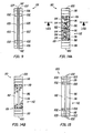
Now referring to Figure 14A, a side cross-sectional view of a framed bipolar plate 110
is shown with hollow tubes inserted to provide a fluid passage, such as for cooling. The framed
bipolar plate 110 comprises a frame 100 and a metal foam bipolar plate 112. The bipolar plate
112 is constructed in a similar fashion to the bipolar plate 80 shown in Figure 6. However, prior
to forming the polymer gas barrier 84 in the first metal foam sheet 82, a plurality of grooves 114
are cut into the face 88. A plurality of hollow tubes 116 are then disposed into the grooves 114.
Upon application of the polymer, the tubes 116 are held firmly within the grooves 114 and the
gas barrier 84 is formed. Any polymer covering the electrically contacting surfaces of the face
88 is cleaned off and positioned in intimate contact with the second metal foam sheet 86. The
two sheets 82,86 are then spot welded or otherwise positioned within the frame 100 for use in
an electrochemical cell. While the hollow tubes may be used solely for purposes of cooling the
cell, the present invention specifically includes the use of water permeable tubes in combination
with a water permeable polymer gas barrier.
Now referring to Figure 14B, a cross-sectional view of the framed bipolar plate 110 is
shown as taken along a line 14B-14B in Figure 14A. The hollow tubes 116 preferably extend
beyond the metal foam sheets 82,86 and communicate with the manifold 118. The frame 100
is preferably formed of a plastic material formed around the bipolar plate 112 with hollow tubes
116 by any available process, such as injection molding. During injection molding of the frame
100, the plastic material is forced into the pores in the edge regions 119 of the metal foam sheets
82,86 to form a permanent attachment.
Now referring to Figure 15, a cross-sectional view of a framed bipolar plate 120 is shown
having an alternate frame securing a bipolar plate 112 having tubes 116 extending therefrom.
The bipolar plate 112 is positioned within two dual frame members 103 and two gaskets 122,
each having mating holes therein to form the manifolds 118. The tubes 116 are received between
the gaskets 122 and communicate with the manifolds 118. The gaskets 122 are preferably made
of a highly elastic material, such as unsintered polytetrafluoroethylene (PTFE), which will
conformably seal around the tubes 116 and between the frame members 103. Note that it is not.
necessary to attach the members of the framed bipolar plate 120 together, since during operation
the members will be placed in intimate contact by compression. The construction and assembly
of an electrochemical cell is described by Murphy ot al. in U.S. Patent No. 5,460,705 which is
incorporated herein by reference.
Now referring to Figures 16A and 16B, front and edge views of a bipolar plate 130 are
shown having metal foam flow fields 132 with channels 134 to improve the gas distribution at
the surface of the adjacent electrodes (not shown) and to reduce the pressure drop of the fluid
passing through the flow fields 132. While the channels 134 may be cut in virtually any
configuration or pattern, it is preferred that the channels do not provide a pathway from one
manifold 118 to the other manifold 118, with the most preferred channels 134 being
interdigitated as shown in Figure 16A. Now referring to Figures 17 and 18, a partial cross-sectional
view and a face view of a lighter version of an all metal bipolar plate 140 is shown
having a metal gas barrier 142 with metal flow fields 144 and polymer cell frame 146 which also
serves as the gasket. The metal gas barrier 142 extends beyond the edges of the flowfield,
preferably to the edges of the stack. The polymer cell frames 146 are preferably positioned on
both sides of the gas barrier 142 in a face-to-face relationship to provide a gas-tight or liquid-tight
seal therebetween. While the frames 146 may be bonded, attached or otherwise secured to
the gas barrier 142 and/or the flow fields 144, it is equally preferred that the frames be positioned
around the perimeter of the flow field and rely on the compression of the stack to provide a seal
with the gas barrier 142.
The relatively thick polymeric frame/gaskets (polymer cell frame 146) positioned on each
side of the gas barrier 142 replace the metal frame typically positioned or secured around the
perimeter of the flow field. This design reduces the weight of the bipolar plate and the resulting
stack by substituting a lower density polymer for the metal frame, and eliminates the need for
any thin gaskets as may be typically required between a metal frame and adjacent metal
components. The polymer cell frame 146, as illustrated in Figure 18, furnishes sealing and gas
channeling between the manifolds 148 and the metal flow field 144.
Now referring to Figure 19, a fluid cooled bipolar plate 150 is shown assembled from a
series of planar components including two cooling fluid barriers 156 and a cooling fluid frame
158, with an electrically conducting flowfield (not shown) therein. Optionally, the fluid cooled
bipolar plate 150 may further include an anode cell frame 154, cathode cell frame 160 and
sealing plates 152. This version of the bipolar plate includes an internal cooling flow field for
cooling the stack. The cooling fluid flows from a cooling fluid inlet manifold 162 through the
cooling flow field (not shown) within the cooling fluid frame 158, and into a cooling fluid outlet
manifold generally opposed from the inlet manifold 162. The flow fields in the anode cell frame
154, cooling fluid frame 158 and cathode cell frame 160 have been omitted from Figure 19 for
purposes of simplification.
Figure 20 provides a polarization curve, demonstrating the performance of a four-cell fuel
cell stack having two bipolar plates with internal water cooling as in Figure 19 and one with only
a gas barrier, and no cooling. The stack had cells with an active area of 32 cm2 and operated on
hydrogen and air at a pressure of 10 psig and a temperature of 62°C.
While the foregoing is directed to the preferred embodiment of the present invention,
other and further embodiments of the invention may be devised without departing from the basic
scope thereof, and the scope thereof is determined by the claims which follow.
The Invention is Summarised in the Following Numbered Clauses
1. A separator for electrochemical cells, comprising a gas barrier having an
electrically conducting pathway extending therethrough; a porous, electrically
conducting member in electrical contact with each side of the electrically
conducting pathway, the member selected from the group consisting of
expanded metal mesh, metal foam, conducting polymer foam, porous
conductive carbon material and combinations thereof.
2. The separator of Clause 1, wherein the electrically conducting pathway
through the gas barrier is formed from a second porous, electrically conducting
member selected from the group consisting of expanded metal mesh, metal
foam, conducting polymer foam, porous conductive carbon material and
combinations thereof.
3. The separator of Clause 1, wherein the gas barrier is a metal.
4. The separator of Clause 1, wherein the gas barrier comprises a polymer.
5. The separator of Clause 1 further comprising a cooling fluid channel
within the gas barrier.
6. The separator of Clause 1, wherein the gas barrier and the porous,
electrically conducting member are essentially parallel.
7. A separator for electrochemical cells, comprising a porous, electrically
conducting sheet selected from the group consisting of expanded metal mesh,
metal foam, conducting polymer foam, porous conductive carbon material and
combinations thereof, and a gas impermeable material disposed within a portion
of the sheet to form a gas barrier.
8. The separator of Clause 7, wherein the gas impermeable material is
selected from the group consisting of polymers and metals.
9. The separator of Clause 7, wherein the gas impermeable material is a
polymer selected from the group consisting of water permeable polymers,
thermoplastic polymers, reactively cured polymers and combinations thereof.
10. The separator of Clause 7, wherein the gas impermeable material is an
epoxy.
11. The separator of Clause 7, wherein the gas impermeable material is a
thermoplastic polymer selected from the group consisting of polyethersufone
(PES), nylon and polycarbonate.
12. The separator of Clause 7, wherein the gas impermeable material is a
perfluorinated sulfonic acid polymer.
13. The separator of Clause 7, wherein the gas impermeable material is
selected from the group consisting of titanium, stainless steel, aluminium,
magnesium and alloys thereof.
14. The separator of Clause 7, wherein the gas barrier is formed along one
face of the porous sheet.
15. The separator of Clause 7, wherein the gas barrier is formed within a
central portion of the porous sheet.
16. The separator of Clause 7, further comprising as second porous,
electrically conducting sheet selected from the group consisting of expanded
metal mesh, metal foam, conducting polymer foam, porous conductive carbon
material and combinations thereof, wherein the second porous sheet is in
electrical contact with the side of the porous sheet having the gas barrier.
17. The separator of Clause 6, wherein the cooling fluid channel.
18. The separator of Clause 16, wherein the cooling fluid channel is
disposed through or in contact with the gas impermeable material.
19. The separator of Clause 17, wherein the cooling fluid channels comprise
a plurality of cooling fluid tubes.
20. A separator for electrochemical cells, comprising two porous,
electrically conducting sheets selected from the group consisting of expanded
metal mesh, metal foam, conducting polymer foam, porous conductive carbon
material and combinations thereof, and an electrically conducting gas barrier
disposed in electrical contact between the sheets.
21. The separator of Clause 18,wherein the electrically conducting gas
barrier is a metal sheet.
22. The separator of Clause 19, wherein the metal sheet is titanium.
23. The separator of Clause 19 further comprising a polymeric cell frame
peripherally enclosing a porous electrically conducting sheet.
24. The separator of Clause 23 wherein the polymeric cell frame includes
channels in fluid communication with the porous electrically conducting sheet.
25. The separator of Clause 20, wherein the porous, electrically conducting
sheets have interdigitated channels communicating to the edge of the sheets.
26. The separator of Clause 20 further comprising a cooling fluid channel
within the electrically conducting gas barrier.
27, A fluid cooled bipolar plate comprising an electrically conducting anode
flow field, an electrically conducting cathode flow field and an electrically
conducting fooling fluid flow field in electrical communication between the
anode flow field and the cathode flow field, wherein the cooling fluid flow
field includes fluid impermeable barriers defining a fluid passage.
28. The fluid cooled bipolar plate of Clause 27 further comprising cooling
fluid inlet and outlet mainfolds connected to the cooling fluid flow field.
29. The fluid cooled bipolar plate of Clause 27 further comprising a frame
disposed around the cooling fluid flow field.