EP1484624A1 - Dispersion compensating optical fiber - Google Patents

Dispersion compensating optical fiber Download PDF

Info

Publication number
EP1484624A1
EP1484624A1 EP03712680A EP03712680A EP1484624A1 EP 1484624 A1 EP1484624 A1 EP 1484624A1 EP 03712680 A EP03712680 A EP 03712680A EP 03712680 A EP03712680 A EP 03712680A EP 1484624 A1 EP1484624 A1 EP 1484624A1
Authority
EP
European Patent Office
Prior art keywords
dispersion
dispersion compensating
core section
compensating fiber
module
Prior art date
Legal status (The legal status is an assumption and is not a legal conclusion. Google has not performed a legal analysis and makes no representation as to the accuracy of the status listed.)
Withdrawn
Application number
EP03712680A
Other languages
German (de)
French (fr)
Other versions
EP1484624A4 (en
Inventor
Kazuhiko Fujikura Ltd. Sakura Works AIKAWA
Shogo 2Fujikura Ltd. Sakura Works SHIMIZU
Ryuji Fujikura Ltd. Sakura Works SUZUKI
Masakazu Fujikura Ltd. Sakura Works NAKAYAMA
Kuniharu Fujikura Ltd. Sakura Works HIMENO
Current Assignee (The listed assignees may be inaccurate. Google has not performed a legal analysis and makes no representation or warranty as to the accuracy of the list.)
Fujikura Ltd
Original Assignee
Fujikura Ltd
Priority date (The priority date is an assumption and is not a legal conclusion. Google has not performed a legal analysis and makes no representation as to the accuracy of the date listed.)
Filing date
Publication date
Application filed by Fujikura Ltd filed Critical Fujikura Ltd
Publication of EP1484624A1 publication Critical patent/EP1484624A1/en
Publication of EP1484624A4 publication Critical patent/EP1484624A4/en
Withdrawn legal-status Critical Current

Links

Images

Classifications

    • GPHYSICS
    • G02OPTICS
    • G02BOPTICAL ELEMENTS, SYSTEMS OR APPARATUS
    • G02B6/00Light guides; Structural details of arrangements comprising light guides and other optical elements, e.g. couplings
    • G02B6/02Optical fibres with cladding with or without a coating
    • G02B6/036Optical fibres with cladding with or without a coating core or cladding comprising multiple layers
    • G02B6/03616Optical fibres characterised both by the number of different refractive index layers around the central core segment, i.e. around the innermost high index core layer, and their relative refractive index difference
    • G02B6/03638Optical fibres characterised both by the number of different refractive index layers around the central core segment, i.e. around the innermost high index core layer, and their relative refractive index difference having 3 layers only
    • G02B6/03644Optical fibres characterised both by the number of different refractive index layers around the central core segment, i.e. around the innermost high index core layer, and their relative refractive index difference having 3 layers only arranged - + -
    • GPHYSICS
    • G02OPTICS
    • G02BOPTICAL ELEMENTS, SYSTEMS OR APPARATUS
    • G02B6/00Light guides; Structural details of arrangements comprising light guides and other optical elements, e.g. couplings
    • G02B6/02Optical fibres with cladding with or without a coating
    • G02B6/02214Optical fibres with cladding with or without a coating tailored to obtain the desired dispersion, e.g. dispersion shifted, dispersion flattened
    • G02B6/02219Characterised by the wavelength dispersion properties in the silica low loss window around 1550 nm, i.e. S, C, L and U bands from 1460-1675 nm
    • G02B6/02252Negative dispersion fibres at 1550 nm
    • G02B6/02261Dispersion compensating fibres, i.e. for compensating positive dispersion of other fibres
    • GPHYSICS
    • G02OPTICS
    • G02BOPTICAL ELEMENTS, SYSTEMS OR APPARATUS
    • G02B6/00Light guides; Structural details of arrangements comprising light guides and other optical elements, e.g. couplings
    • G02B6/02Optical fibres with cladding with or without a coating
    • G02B6/02395Glass optical fibre with a protective coating, e.g. two layer polymer coating deposited directly on a silica cladding surface during fibre manufacture
    • GPHYSICS
    • G02OPTICS
    • G02BOPTICAL ELEMENTS, SYSTEMS OR APPARATUS
    • G02B6/00Light guides; Structural details of arrangements comprising light guides and other optical elements, e.g. couplings
    • G02B6/02Optical fibres with cladding with or without a coating
    • G02B6/036Optical fibres with cladding with or without a coating core or cladding comprising multiple layers
    • G02B6/03616Optical fibres characterised both by the number of different refractive index layers around the central core segment, i.e. around the innermost high index core layer, and their relative refractive index difference
    • G02B6/03622Optical fibres characterised both by the number of different refractive index layers around the central core segment, i.e. around the innermost high index core layer, and their relative refractive index difference having 2 layers only
    • G02B6/03627Optical fibres characterised both by the number of different refractive index layers around the central core segment, i.e. around the innermost high index core layer, and their relative refractive index difference having 2 layers only arranged - +
    • GPHYSICS
    • G02OPTICS
    • G02BOPTICAL ELEMENTS, SYSTEMS OR APPARATUS
    • G02B6/00Light guides; Structural details of arrangements comprising light guides and other optical elements, e.g. couplings
    • G02B6/02Optical fibres with cladding with or without a coating
    • G02B6/028Optical fibres with cladding with or without a coating with core or cladding having graded refractive index
    • G02B6/0281Graded index region forming part of the central core segment, e.g. alpha profile, triangular, trapezoidal core

Definitions

  • the present invention relates to a dispersion compensating fiber which compensates a chromatic dispersion for a 1.3 ⁇ m band zero-dispersion single-mode fiber (Standard Single-mode Fiber, hereinafter called an "S-SMF” for short) which has a zero-dispersion wavelength in 1.3 ⁇ m band or a non-zero dispersion shift fiber (Non-Zero Dispersion Shifted Fiber, hereinafter called as "NZ-DSF” for short.
  • S-SMF Standard Single-mode Fiber
  • NZ-DSF non-zero dispersion Shifted Fiber
  • the present invention relates to a dispersion compensating fiber in which there are few deterioration in characteristics even if it is formed to be a module by winding in a small reel.
  • the S-SMF is commonly used all over the world presently. If a transmission for 1.55 ⁇ m band is performed by using this optical fiber network, a chromatic dispersion of approximately +17 ps/nm/km is generated in this 1.55 ⁇ m band. Therefore, if a signal is transmitted by using this optical fiber, the transmission characteristics deteriorates greatly by an influence of the accumulated chromatic dispersion in a long distance transmission. Also, although an NZ-DSF which has a smaller chromatic dispersion in 1.55 ⁇ m band than in the S-SMF is installed mainly for a long distance transmission path, it is necessary to compensate the chromatic dispersion which is accumulated on the transmission path.
  • WDM wavelength division multiplexing
  • a code for a dispersion slope of the dispersion compensating fiber is opposite to a code for a dispersion slope for a transmission optical fiber, there is a case in which a residual dispersion may be small in a wide range of band.
  • An RDS is named for an index for indicating a performance for compensating this dispersion slope.
  • the RDS (RDS; Relative Dispersion Slope) is a ratio of a dispersion slope with reference to the chromatic dispersion.
  • RDS can be shown in a following formula (1) under condition that D indicates the chromatic dispersion and S indicates the dispersion slope.
  • RDS S/D
  • Japanese Unexamined Patent Application, First Publication No. Hei 6-11620 discloses a technology for a dispersion compensating fiber which has a chromatic dispersion which is -20 ps/nm/km or lower for compensating the chromatic dispersion in 1.55 ⁇ m band in an S-SMF which has a zero-dispersion wavelength in the wavelength 1.3 ⁇ m band.
  • Japanese Unexamined Patent Application, First Publication No. 11-95056 discloses a technology for a dispersion compensating fiber in which a dispersion slope is reduce while reducing a connection loss such that an absolute value for the chromatic dispersion per a unit length is increased.
  • Japanese Unexamined Patent Application, First Publication No. Hei 8-136758 discloses a technology for a dispersion compensating fiber in which the dispersion slope is minus such that the chromatic dispersion is -100 ps/nm/km or lower.
  • Japanese Unexamined Patent Application, First Publication No. Hei 8-54546 discloses a small-diameter dispersion compensating fiber which has a primary coating layer of which Young's modulus is 0.1 kgf/mm 2 on an outer periphery of an optical fiber bare line (cladding) of which outer diameter is smaller than 125 ⁇ m and has a secondary coating layer of which Young's modulus is 150 kgf/mm 2 or greater on an outer periphery of the primary coating layer in an optical fiber which has a coating structure shown in FIG. 2.
  • a small-diameter dispersion compensating fiber is disclosed which has 60 ⁇ m cladding, 160 ⁇ m coating, and -80.0 ps/nm/km.
  • Japanese Unexamined Patent Application, First Publication No. Hei 10-115725 discloses a technology for a dispersion compensating fiber which is connected to an optical fiber which has a chromatic dispersion in a transmission wavelength and compensates the above explained chromatic dispersion so as substantially to eliminate the chromatic dispersion in an entire transmission system in the transmission wavelength band. Also, Japanese Unexamined Patent Application, First Publication No.
  • Hei 10-115725 discloses a technology for a dispersion compensating fiber for reducing the chromatic dispersion in an entire transmission system in the transmission wavelength as close as zero which has a multi-layer structure such as at least two layers or more which comprises a core which is formed by a silica glass, a cladding which is formed by a silica glass on an outer periphery of the core, and a coating layer which is formed by a plastic resin on an outer periphery of the cladding such that an outer diameter is smaller than 250 ⁇ m, the coating layer has 20 ⁇ m thickness or greater, and an outer layer which has a Young's modulus which is higher than that of an inner layer.
  • a multi-layer structure such as at least two layers or more which comprises a core which is formed by a silica glass, a cladding which is formed by a silica glass on an outer periphery of the core, and a coating layer which is formed by a plastic resin on an outer periphery of the
  • a small-diameter dispersion compensating fiber is disclosed in this Japanese Unexamined Patent Application, First Publication No. Hei 10-115725 and in embodiments in a specification of US Patent No. 5,887,104 such that a diameter of an outer cladding is 60 ⁇ m to 125 ⁇ m, an outer diameter of coating is 110 ⁇ m to 250 ⁇ m, and the chromatic dispersion is approximately -105 ps/nm/km.
  • Such a dispersion compensating fiber is formed to be a module by disposing in a casing for winding a coil of which length is 1/5 to 1/7 of the transmission optical fiber.
  • a size of the module should be constant with regardless to a necessary amount for compensating the dispersion. Even if an absolute amount of the dispersion which is compensated is great, it is necessary to wind the dispersion compensating fiber as long as possible in a small case. Furthermore, it is preferable that this module for the dispersion compensating fiber should be as small as possible so as to form a small transmission device.
  • a volume of the module depends on a volume for winding the dispersion compensating fiber.
  • a winding volume is indicated by a product for a cross sectional area which includes a coating and a fiber length of the dispersion compensating fiber.
  • dispersion compensating fiber is formed such that its diameter should be as small as possible for forming a small module as disclosed in the Japanese Unexamined Patent Application, First Publication No. Hei 8-54546, Japanese Unexamined Patent Application, First Publication No. Hei 10-115725, or US Patent No. 5,887,104.
  • the dispersion compensating fiber has been made such that an absolute value for the chromatic dispersion per a unit length unless the transmission loss is deteriorated, and an optical characteristic and reliability are not deteriorated; thus, the diameter of the optical fiber should be as small as possible in an allowable range.
  • the technology which are disclosed in the above mentioned publication and a report by an institute was not sufficient for realizing a small module while restricting an increase of a loss which is caused by a bending loss over an entire range of the operating wavelength.
  • the present invention was made for solving the above mentioned problems.
  • the present invention was invented so as to realize an stable temperature characteristics with a low loss and a low PMD in a dispersion compensating fiber such that a volume ratio should be less than a half with reference to a module of the conventional dispersion compensating fiber.
  • An object of the present invention is to provide a dispersion compensating fiber such that a fluctuation of a module loss should be within ⁇ 0.5 dB in a temperature range (-5 °C to +70°C) which is used ordinarily even if a module of the dispersion compensating fiber is produced.
  • a first aspect of the present invention is a dispersion compensating fiber in which, in at least a wavelength which is selected from 1.53 ⁇ m to 1.63 ⁇ m, a bending loss is 5 dB/m or lower when it is wound by a 20 mm bending diameter, a chromatic dispersion is -120ps/nm/km or lower, an absolute value of the chromatic dispersion per a unit loss is 200 ps/nm/dB or higher, a cut-off wavelength for used length and used condition is 1.53 ⁇ m or lower, an outer diameter of a cladding is 80 ⁇ m to 100 ⁇ m, an outer diameter of coating is 160 ⁇ m to 200 ⁇ m, and a an adhesive property of a surface of a coating resin is 10gf/mm or lower.
  • the adhesive property is measured by the following method. First, the optical side dancer roll. Then, it is introduced into a receiving roll through a first fixed roll, a moving roll and a second fixed roll, and is set to a tension pickup between the moving roll and the second fixed roll.
  • the optical fiber passed through the receiving roll is mounted on a winding roll through a winding side dancer roll similar to the transmitting side dancer roll. Then the winding roll is rotated to impart a fixed tension to the optical fiber.
  • the tension pickup detects the moving quantity of a detecting roll by the tension of the optical fiber to detect the tension, and displays and records it on a monitor. In this case, since the tension change added to the optical fiber becomes a value according to the surface tackiness, the surface tackiness of the optical fiber can be easily and quantitively measured and evaluated.
  • a second aspect of the present invention is a dispersion compensating fiber in which the an adhesive property of the surface of the coating resin of the dispersion compensating fiber is 1gf/mm or lower.
  • a third aspect of the present invention is a dispersion compensating fiber in which a Young's modulus of a primary coating layer which is disposed on an outer periphery of the cladding is 0.15kgf/mm 2 , a thickness of the primary coating layer is 20 ⁇ m to 30 ⁇ m, a Young's modulus of a secondary coating layer which is disposed on an outer periphery of the primary coating layer is 50kgf/mm 2 , and a thickness of the secondary coating layer is 15 ⁇ m to 30 ⁇ m.
  • a fourth aspect of the present invention is a dispersion compensating fiber which comprises at least a core and a cladding which is disposed on an outer periphery of the core.
  • a refractive index difference of the center core section with reference to the cladding is +1.6% to +2.6%
  • a refractive index difference of the intermediate core section with reference to the cladding is -0.30% to -1.4%
  • a refractive index difference of the ring core section with reference to the cladding is +0.30% to +1.0%
  • a ratio of a radius of the intermediate core section with reference to a radius of the center core section is 1.5 to 3.5
  • a ratio of a radius of the intermediate core section with reference to a radius of the ring core section is 1.2 to 2.0
  • a radius of the core is 4 ⁇ m to 8 ⁇ m.
  • a fifth aspect of the present invention is a dispersion compensating fiber which comprises at least a core which is formed at least the center core section and the intermediate core section, and a cladding, such that a refractive index difference of the center core section with reference to the cladding is +1.6% to +2.6%; a refractive index difference of the intermediate core section with reference to the cladding is -0.30% to -1.4%;a ratio of a radius of the intermediate core section with reference to a radius of the center core section is 1.5 to 3.5;a ratio of a radius of the intermediate core section with reference to a radius of the ring core section is 1.2 to 2.0, and a radius of the core is 4 ⁇ m to 8 ⁇ m.
  • the dispersion compensating fiber of the present invention is intended to specify a structural parameter and a characteristic value of the dispersion compensating fiber.
  • a quotient which is obtained by dividing the dispersion slope by the chromatic dispersion is 0.0026nm -1 to 0.010 nm -1 .
  • the RDS in 1.53 ⁇ m to 1.57 ⁇ m is 0.0026 nm -1 to 0.010nm -1 , it is possible to realize a dispersion compensating fiber which is suitable for the S-SMF which has an RDS typically such as 0.0034 nm -1 in 1.55 ⁇ m and an NZ-DSF which has a typical RDS such as 0.007 nm -1 to 0.010 nm -1 .
  • a quotient which is obtained by dividing the dispersion slope by the chromatic dispersion is 0.0026nm -1 to 0.0041 nm -1 .
  • the RDS is 0.0026nm -1 to 0.0041 nm -1 ; thus, is it possible to realize a dispersion compensating fiber which is suitable for the S-SMF which has typically an RDS such as 0.0034 nm -1 .
  • a quotient which is obtained by dividing the dispersion slope by the chromatic dispersion is 0.0022nm -1 to 0.010 nm -1 .
  • the RDS in 1.57 ⁇ m to 1.63 ⁇ m is 0.0022 nm -1 to 0.010nm -1 , it is possible to realize a dispersion compensating fiber which is suitable for the S-SMF which has an RDS typically such as 0.0029 nm -1 in 1.59 ⁇ m and an NZ-DSF which has a typical RDS such as 0.005 nm -1 to 0.010 nm -1 .
  • a quotient which is obtained by dividing the dispersion slope by the chromatic dispersion is 0.0022nm -1 to 0.0035 nm -1 .
  • the RDS is 0.0026nm -1 to 0.0035 nm -1 in 1.57 ⁇ m to 1.63 ⁇ m; thus, is it possible to realize a dispersion compensating fiber which is suitable for the S-SMF which has typically an RDS such as 0.0029 nm -1 in 1.59 ⁇ m.
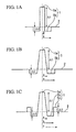
  • reference numeral 1a indicates a center core section.
  • Reference numeral 1b indicates an intermediate core section which is disposed on an outer periphery of the center core section 1a.
  • Reference numeral 2 indicates a cladding which is disposed on an outer periphery of the intermediate core section 1b.
  • reference numeral 1a indicates a center core section.
  • Reference numeral 1b indicates an intermediate core section which is disposed on an outer periphery of the center core section 1a.
  • Reference numeral 1c indicates a ring core section which is disposed on an outer periphery of the intermediate core section 1b.
  • Reference numeral 2 indicates cladding which is disposed on an outer periphery of the ring core section 1c.
  • a letter a indicates a radius of the center core section 1a.
  • a letter b indicates a radius of the center core section 1b.
  • a letter c indicates a radius of the ring core section 1c.
  • a refractive index difference of the center core section 1a with reference to the cladding 2 is indicated by ⁇ 1.
  • a refractive index difference of the intermediate core section 1b with reference to the cladding 2 is indicated by ⁇ 2.
  • a refractive index difference of the ring core section 1c with reference to the cladding 2 is indicated by ⁇ 3.
  • the center core section 1a has a refractive index which is greater than the refractive index of the cladding 2.
  • the intermediate core section 1b has a refractive index which is smaller than the refractive index of the cladding 2.
  • the ring core section 1c has a refractive index which is greater than the refractive index of the cladding 2.
  • a ratio b/a of the radius of the intermediate core section with reference to the radius of the center core section is 1.5 to 3.5
  • a ratio c/b of the radius of the ring core section with reference to the radius of the intermediate core section is 1.2 to 2.0
  • a radius of the core is 4 ⁇ m to 8 ⁇ m
  • a refractive index difference ⁇ 1 of the center core section 1a with reference to the cladding 2 is +1.6 % to +2.6%
  • a refractive index difference ⁇ 2 of the intermediate core section 1b with reference to the cladding 2 is -0.30% to -1.4%
  • a refractive index difference ⁇ 3 of the ring core section 1c with reference to the cladding 2 is +0.30% to +1.0%.
  • the dispersion compensating fiber in this example is specified by specific values below in addition to these structures. Such specific values are such that, in at least a wavelength which is selected from 1.53 ⁇ m to 1.63 ⁇ m, a bending loss is 5 dB/m or lower when it is wound by a 20 mm bending diameter, a chromatic dispersion is -120ps/nm/km or lower, an absolute value of the chromatic dispersion per a unit loss is 200 ps/nm/dB or higher, a cut-off wavelength for used length and used condition is 1.53 ⁇ m or lower, an outer diameter of a cladding is 80 ⁇ m to 100 ⁇ m, an outer diameter of coating is 160 ⁇ m to 200 ⁇ m, and a an adhesive property of a surface of a coating resin is 10gf/mm or lower, more preferably 1 gf/mm or lower.
  • the chromatic dispersion is in a range in which it is possible to realize approximately -300 ps/nm/km or greater from a view point of a range for controlling a refractive index difference and a bending loss.
  • An absolute value for the chromatic dispersion per a unit loss is in a range in which it is possible to realize approximately 500 ps/nm/dB from a view point of a value of the transmission loss.
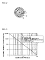
  • FIG. 2 A structure of a coating layer of this dispersion compensating fiber is shown in FIG. 2.
  • reference numeral 1 indicates a core.
  • Reference numeral 2 indicates a cladding which is formed around the core 1.
  • a primary coating layer 3 is formed on an outer periphery of the cladding 2.
  • a secondary coating layer 4 is formed on an outer periphery of the primary coating layer 3. It is preferable that the Young's modulus of the primary coating layer should be 0.15 kgf/mm 2 or lower. Also, it is preferable that the Young's modulus of the secondary coating layer should be 50 kgf/mm 2 or greater.
  • a main role for each of the coating layer is such that the primary coating layer serves for a shock-absorbing member so as to contact a surface of a glass member and the secondary coating layer serves for maintaining a strength for an optical fiber. Therefore, it is preferable if both the primary coating layer and the secondary coating layer are thick. However, if both of them are thick, it is not possible to realize a purpose for providing a small module for a dispersion compensating fiber by forming the dispersion compensating fiber in a small radius. Also, if the Young's modulus of the primary coating layer exceeds 0.15 kgf/mm 2 , an external influence disturbs the optical fiber directly. Consequently, a micro-bend loss, etc. is generated; thus, a transmission loss is deteriorated.
  • the Young's modulus of the secondary coating layer is less than 50 kgf/mm 2 , it is not possible to maintain the strength of the optical fiber.
  • These values relates to thickness of each layer. It is preferable that the thickness of the primary coating layer is 20 ⁇ m to 30 ⁇ m, and the thickness of the secondary coating layer is 15 ⁇ m to 30 ⁇ m. Therefore, the relationship between these is shown in formulae (2), (3). It is preferable to use a resin of which Young's modulus satisfies conditions in these formulae from a fiber strength point of view. 0.06 ⁇ 10 -3 ⁇ S 1 ⁇ E 1 ⁇ 1.3 ⁇ 10 -3 0.3 ⁇ S 2 ⁇ E 2 ⁇ 3.0
  • S 1 indicates a cross sectional area [mm 2 ] for the primary coating layer
  • E 1 indicates a Young's modulus [kgf/mm 2 ] in the primary coating layer
  • S 2 indicates a cross sectional area [mm 2 ] of the secondary coating layer
  • E 2 indicates a Young's modulus [kgf/mm 2 ] in the secondary coating layer.
  • an outer diameter of the cladding 2 is 80 ⁇ m to 100 ⁇ m, and an outer diameter of a coating which is formed by the primary coating layer 3 and the secondary coating layer 4 is 160 ⁇ m to 200 ⁇ m.
  • an outer diameter of the cladding 2 exceeds 100 ⁇ m so as to secure a necessary coating thickness, an outer diameter of coating is inevitably greater; thus, such a condition cannot be consistent with a purpose for providing a small module.
  • an outer diameter of the cladding 2 is smaller than 80 ⁇ m, the cladding thickness is too thin; thus, it is vulnerable to an influence of a micro-bend, etc.; thus, a loss characteristics is deteriorated.
  • the outer diameter of the cladding 2 should be 80 ⁇ m or greater.
  • an outer diameter of a coating which is formed by the primary coating layer 3 and the secondary coating layer 4 exceeds 200 ⁇ m, such an effect is not so great.
  • the outer diameter of the coating is smaller than 160 ⁇ m, the thickness of the primary coating layer and the thickness of the secondary coating layer are too thin; thus, it may be more feasible that it will be disturbed by a micro-bend, etc., or a deterioration of a strength in an optical fiber itself may occur.
  • a module for a dispersion compensating fiber is produced by winding a dispersion compensating fiber of which diameter is formed to be small, a temperature characteristics for the module loss is deteriorated because of the surface an adhesive property. It is possible to realize a module for a dispersion compensating fiber which has a stable temperature characteristics such as a ⁇ 0.5 dB or smaller fluctuation of the module loss in an ordinary operating temperature range (-5°C to +70°C) by forming the surface an adhesive property to be 10 gf/mm or smaller, more preferably 1gf/mm or smaller even if a module for a dispersion compensating fiber is produced by winding it on a small coil.
  • methods can be named such as using an ultraviolet-ray-curable resin which contains 1 to 5 wt % of silicone component or forming the ultraviolet-ray-curable resin so as to have an 2 % or lower atmospheric oxygen density which is more preferably 0 %.
  • a dispersion compensating fiber which can be contained in a small module in which a module loss is low and there is not an outstanding increase in a loss in a long wavelength band which is caused by the bending loss and the micro-bend characteristics with compared to a conventional module for a dispersion compensating fiber even if it is wound in a small reel. It is possible to realize a module for a dispersion compensating fiber which has a stable temperature characteristics such as a ⁇ 0.5 dB or smaller fluctuation of the module loss in an ordinary operating temperature range (-5°C to +70°C).
  • a second example for a dispersion compensating fiber according to the present invention is formed such that, in a W-type refractive index profile as shown in FIGS. 1(a), (b), a ratio b/a of a radius of the intermediate core section with reference to the radius of the center core section is 1.5 to 3.5, a radius of the core is 4 ⁇ m to 8 ⁇ m, a relative refractive index difference ⁇ 1 of the center core section 1a with reference to the cladding 2 is +1.6 % to +2.6 %, a relative refractive index difference ⁇ 2 of the intermediate core section 1b with reference to the cladding 2 is -0.30 % to -1.4 %.
  • the dispersion compensating fiber in this example is specified by specific values below in addition to these structures. Such specific values are such that, in at least a wavelength which is selected from 1.53 ⁇ m to 1.63 ⁇ m, a bending loss is 5 dB/m or lower when it is wound by a 20 mm bending diameter, a chromatic dispersion is -120ps/nm/km or lower, an absolute value of the chromatic dispersion per a unit loss is 200 ps/nm/dB or higher, a cut-off wavelength for used length and used condition is 1.53 ⁇ m or lower, an outer diameter of a cladding is 80 ⁇ m to 100 ⁇ m, an outer diameter of coating is 160 ⁇ m to 200 ⁇ m, and a an adhesive property of a surface of a coating resin is 10gf/mm or lower, more preferably 1 gf/mm or lower.
  • a PMD it is preferable to be 0.3 ps/vkm orin any one of the above explained first and the second example. More preferably, it is 0.2 ps/vkm lower.
  • a PMD is a mode dispersion which is caused because a degeneracy is released by forming a core of a single-mode optical fiber in an oval shape; thus, a group delay difference is generated between a two orthogonal polarization modes. Therefore, the PMD has not been a big problem because it has been possible to ignore the PMD in a conventional communication speed. However, the PMD is a factor for a cause of a transmission characteristics deterioration in a large-capacity optical communication system.
  • a limitation for a transmission distance for the PMD can be represented by a formula (4) below.
  • B indicates a transmission speed [Gb/s]
  • PMD indicates a polarization mode dispersion [ps/vkm]
  • L indicates a fiber length [km]
  • a third example for a dispersion compensating fiber according to the present invention is formed such that, in a W-type refractive index profile as shown in FIGS. 1(a), (b), a ratio b/a of a radius of the intermediate core section with reference to the radius of the center core section is 1.5 to 3.5, a radius of the core is 4 ⁇ m to 8 ⁇ m, a relative refractive index difference ⁇ 1 of the center core section 1a with reference to the cladding 2 is +1.6 % to +2.6 %, a relative refractive index difference ⁇ 2 of the intermediate core section 1b with reference to the cladding 2 is -0.30 % to -1.4 %.
  • a third example for the dispersion compensating fiber according to the present invention is formed such that, in a W-type profile with a ring which is shown in FIG. 1(c), a ratio b/a of the radius of the intermediate core section with reference to the radius of the center core section is 1.5 to 3.5, a ratio c/b of the radius of the ring core section with reference to the radius of the intermediate core section is 1.2 to 2.0, a radius of the core is 4 ⁇ m to 8 ⁇ m, a refractive index difference ⁇ 1 of the center core section 1a with reference to the cladding 2 is +1.6 % to +2.6%, a refractive index difference ⁇ 2 of the intermediate core section 1b with reference to the cladding 2 is -0.30% to -1.4%, and a refractive index difference ⁇ 3 of the ring core section 1c with reference to the cladding 2 is +0.30% to +1.0% Also, the dispersion compensating fiber in this example is specified by specific values below in addition to these structures.
  • Such specific values are such that, in at least a wavelength which is selected from 1.53 ⁇ m to 1.57 ⁇ m, a bending loss is 5 dB/m or lower when it is wound by a 20 mm bending diameter, a chromatic dispersion is -120ps/nm/km or lower, an absolute value of the chromatic dispersion per a unit loss is 200 ps/nm/dB or higher, a cut-off wavelength for used length and used condition is 1.53 ⁇ m or lower, a quotient which is obtained by dividing the dispersion slope by the chromatic dispersion is 0.0026 nm -1 to 0.010 nm -1 , an outer diameter of a cladding is 80 ⁇ m to 100 ⁇ m, an outer diameter of coating is 160 ⁇ m to 200 ⁇ m.
  • a dispersion compensating fiber By using such a dispersion compensating fiber, it is possible to contain it in a small module with compared to a conventional module for a dispersion compensating fiber in which a module loss is low and there is not an outstanding increase in a loss in a long wavelength band which is caused by the bending loss and the micro-bend even if it is wound in a small reel.
  • a dispersion compensating fiber which is suitable for the S-SMF which has an RDS typically such as 0.0034 nm -1 in 1.55 ⁇ m and an NZ-DSF which has a typical RDS such as 0.007 nm -1 to 0.010 nm -1 in 1.55 ⁇ m band.
  • a fourth example for a dispersion compensating fiber according to the present invention is formed such that, in a W-type refractive index profile as shown in FIGS. 1(a), (b), a ratio b/a of a radius of the intermediate core section with reference to the radius of the center core section is 1.5 to 3.5, a radius of the core is 4 ⁇ m to 8 ⁇ m, a relative refractive index difference ⁇ 1 of the center core section 1a with reference to the cladding 2 is +1.6 % to +2.6 %, a relative refractive index difference ⁇ 2 of the intermediate core section 1b with reference to the cladding 2 is -0.30 % to -1.4 %.
  • a fourth example for the dispersion compensating fiber according to the present invention is formed such that, in a W-type profile with a ring which is shown in FIG. 1(c), a ratio b/a of the radius of the intermediate core section with reference to the radius of the center core section is 1.5 to 3.5, a ratio c/b of the radius of the ring core section with reference to the radius of the intermediate core section is 1.2 to 2.0, a radius of the core is 4 ⁇ m to 8 ⁇ m, a refractive index difference ⁇ 1 of the center core section 1a with reference to the cladding 2 is +1.6 % to +2.6%, a refractive index difference ⁇ 2 of the intermediate core section 1b with reference to the cladding 2 is -0.30% to -1.4%, and a refractive index difference ⁇ 3 of the ring core section 1c with reference to the cladding 2 is +0.30% to +1.0% Also, the dispersion compensating fiber in this example is specified by specific values below in addition to these structures
  • Such specific values are such that, in at least a wavelength which is selected from 1.57 ⁇ m to 1.63 ⁇ m, a bending loss is 5 dB/m or lower when it is wound by a 20 mm bending diameter, a chromatic dispersion is -120ps/nm/km or lower, an absolute value of the chromatic dispersion per a unit loss is 200 ps/nm/dB or higher, a cut-off wavelength for used length and used condition is 1.57 ⁇ m or lower, a quotient which is obtained by dividing the dispersion slope by the chromatic dispersion is 0.0022 nm -1 to 0.010 nm -1 , an outer diameter of a cladding is 80 ⁇ m to 100 ⁇ m, an outer diameter of coating is 160 ⁇ m to 200 ⁇ m.
  • the RDS in 1.57 ⁇ m to 1.63 ⁇ m is 0.0022 nm -1 to 0.010 nm -1 .
  • a dispersion compensating fiber which is suitable for the S-SMF which has an RDS typically such as 0.0029 nm -1 in 1.59 ⁇ m and an NZ-DSF which has a typical RDS such as 0.005 nm -1 to 0.010 nm -1 and a chromatic dispersion approximate several ps/nm/km in 1.59 ⁇ m band.
  • Dispersion compensating fibers are produced with a W-type profile shown in FIG. 1(b) and a W-type profile with a ring shown in FIG. 1(c) according to a commonly known method such as a VAD method, an MCVD method, or a PCVD method.
  • a commonly known method such as a VAD method, an MCVD method, or a PCVD method.
  • values such as ⁇ 1, ⁇ 2, ⁇ 3, b/a, c/b, a core radius, a diameter of the cladding, an outer diameter of a primary coating layer, and an outer diameter of a secondary coating layer are made so as to be values shown in a TABLE 1 under condition that an atmospheric oxygen density should be 0.1 % or lower (0.0% when it is displayed) when an ultraviolet-ray-curable resin is hardened while being drawn.
  • a dispersion compensating fiber in No. 1 is produced so as to have an outer diameter of the conventional cladding and a coating structure for a purpose of a comparison.
  • the dispersion compensating fibers shown in No. 2 to No. 6 are examples of the optical fiber according to the present invention.
  • values such as ⁇ 1, ⁇ 2, ⁇ 3, b/a, c/b, and a core radius are set to be values shown in the TABLE 1.
  • a primary coating layer of which Young's modulus is 0.15 kgf/mm 2 or lower and a secondary coating layer of which Young's modulus is 50 kgf/mm 2 or higher are formed on an outer periphery of the cladding of which outer diameter is 80 ⁇ m to 100 ⁇ m.
  • the outer diameter of the coating of this dispersion compensating fiber is as narrow as 160 ⁇ m to 200 ⁇ m; thus, it is possible to form a small module thereby.
  • an optical characteristics for a module of the dispersion compensating fiber and module size are shown in TABLE 3 under condition that a module is formed by winding these dispersion compensating fiber in a small reel of which cylinder diameter is 80 mm by 40 g of winding tension and connecting a 1.3 ⁇ m band zero-dispersion single-mode optical fiber with connecters to both ends thereof.
  • These modules for the dispersion compensating fiber serve for S-SMF 100 km compensation.
  • a dispersion compensating fiber is realized in which a module loss is low, and there is not an increase in a loss which is caused by a bending loss even if it is wound in a small reel and it is possible to contain thereof in a small module of which volume ratio is 50 % or lower with compared to a conventional module for a dispersion compensating fiber.
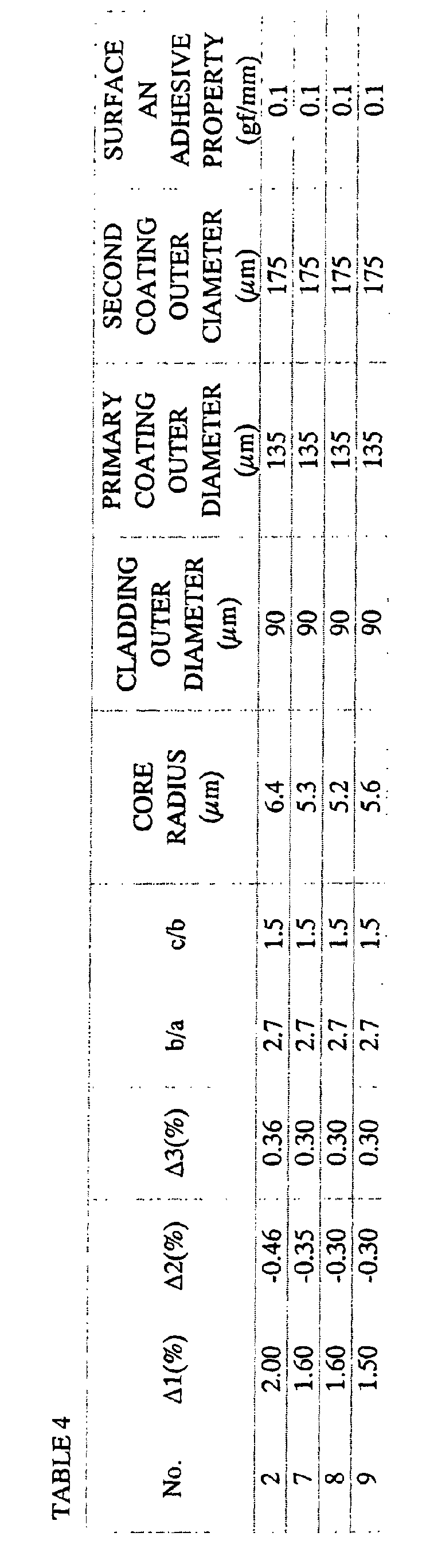
  • dispersion compensating fibers with a W-type profile shown in FIG. 1C are produced according to a commonly known method such as a VAD method, an MCVD method, or a PCVD method. Under such a condition, values such as ⁇ 1, ⁇ 2, ⁇ 3, b/a, c/b, and a core radius are made so as to be values shown in a TABLE 4 under condition that an atmospheric oxygen density should be 0.1 % or lower (0.0% when it is displayed) when an ultraviolet-ray-curable resin is hardened while being drawn.
  • a dispersion compensating fibers in No. 7 to No. 9 are produced so as to have conventional dispersion characteristics for a purpose of a comparison.
  • the dispersion compensating fiber shown in No. 2 is an example of the optical fiber according to the present invention.
  • values such as ⁇ 1, ⁇ 2, ⁇ 3, b/a, c/b, and a core radius are set to be values shown in the TABLE 4.
  • values for the chromatic dispersion were varied without changing the bending loss.
  • the outer diameter of the cladding, Young's modulus and thickness of the primary coating layer, and Young's modulus and thickness of the secondary coating layer are the same.
  • a module is formed by winding these dispersion compensating fiber in a small reel of which cylinder diameter is 80 mm by 40 g of winding tension and connecting a 1.3 ⁇ m band zero-dispersion single-mode optical fiber with connecters to both ends thereof.
  • the module dispersion is -1700 ps/nm which is equivalent for S-SMF 100km compensation.
  • Optical characteristics of the module of the dispersion compensating fiber and the module size are shown in TABLE 6 when they are produced.
  • a module for a dispersion compensating fiber which uses a dispersion compensating fiber No. 7 of which chromatic dispersion is -90ps/nm/km has 47 % of volume ratio with reference to a conventional module.
  • Dispersion compensating fiber No. 8 with -83 ps/nm/km and a dispersion compensating fibers No. 8 and No. 9 which use a dispersion compensating fiber No. 9 with -77 ps/nm/km have 50 % of volume ratio or higher with reference to the conventional module; thus, it is understood that a smaller device is not realized sufficiently.
  • the absolute value for the chromatic dispersion should be 120 ps/nm or higher (-120 ps/nm/km or lower) at least.
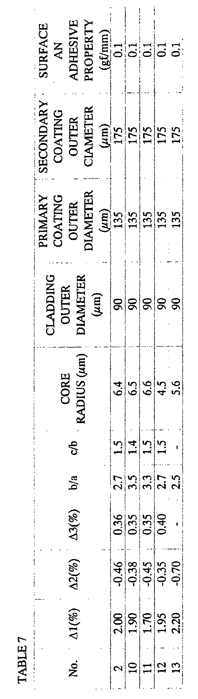
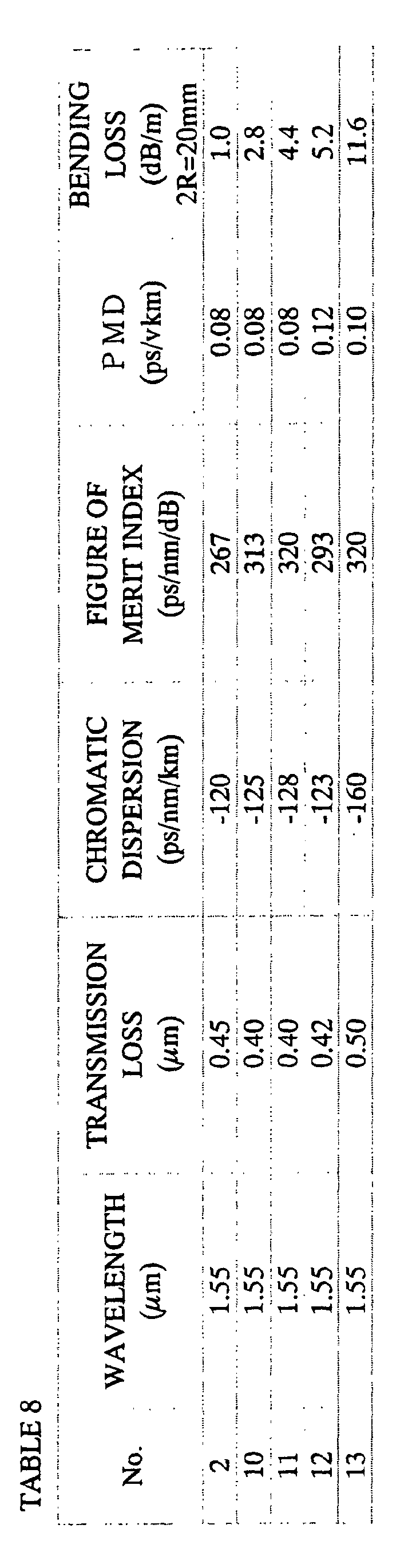
  • a dispersion compensating fibers in No. 12 to No. 13 are produced so as to have conventional dispersion characteristics for a purpose of a comparison.
  • the dispersion compensating fiber shown in No. 2, No. 10, and No. 11 are examples of the optical fiber according to the present invention.
  • values such as ⁇ 1, ⁇ 2, ⁇ 3, b/a, c/b, and a core radius are set to be values shown in the TABLE 8 by changing the bending loss.
  • the outer diameter of the cladding, Young's modulus and thickness of the primary coating layer, and Young's modulus and thickness of the secondary coating layer are the same.
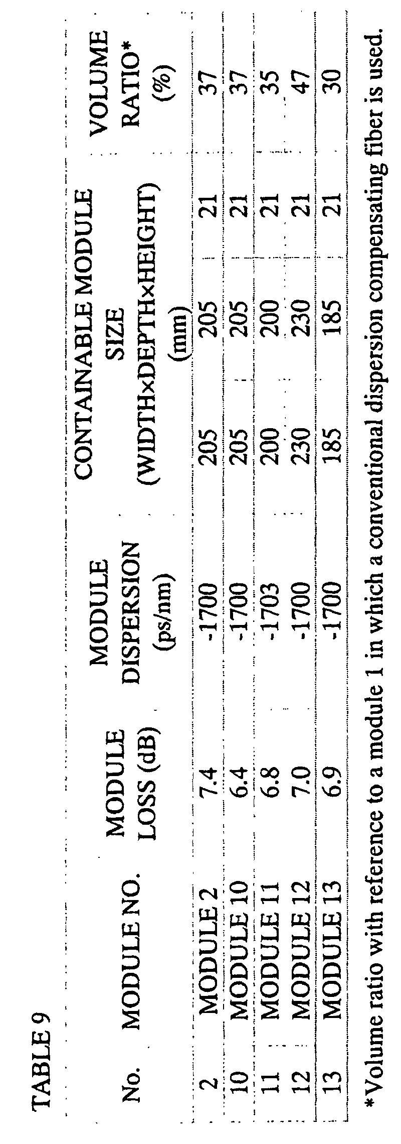
  • Optical characteristics for a module of the dispersion compensating fiber are shown in TABLE 9 under condition that a module is formed by winding these dispersion compensating fiber in a small reel of which cylinder diameter is 80 mm by 40 g of winding tension and connecting a 1.3 ⁇ m band zero-dispersion single-mode optical fiber with connecters to both ends thereof.
  • loss wavelength characteristics of these modules are shown in FIG. 5. Temperature characteristics are shown in FIG. 6.
  • the temperature characteristics for the module loss in the module for the dispersion compensating fiber which has a great bending loss is deteriorated in line with an increase in the bending loss. According to these factors, it is necessary that the bending loss of the dispersion compensating fiber should be 5 dB/m or lower according to the present invention.
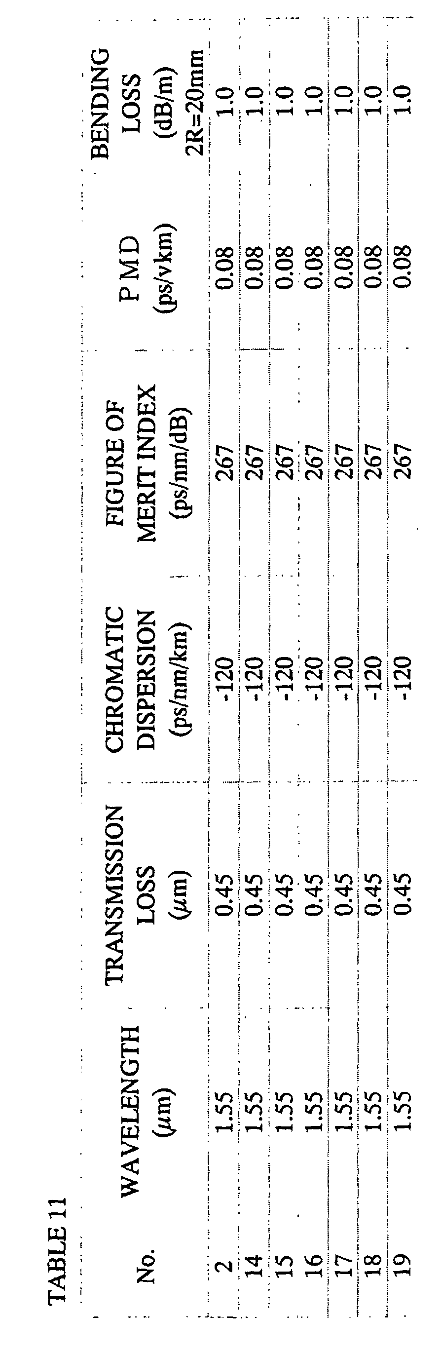
  • dispersion compensating fibers with a W-type profile shown in FIG. 1(c) are produced according to a commonly known method such as a VAD method, an MCVD method, or a PCVD method. Under such a condition, they are produced such that values such as ⁇ 1, ⁇ 2, ⁇ 3, b/a, c/b, and a core radius are made so as to be shown in a TABLE 10. Under such a condition, the outer diameter of the cladding was varied in a range of 60 ⁇ m to 110 ⁇ m. In the primary coating layer and the secondary coating layer, thickness are made constant such as 22.5 ⁇ m and 20 ⁇ m respectively. It is shown in the TABLE 10 together with parameters for refractive index distribution.
  • a dispersion compensating fibers in No. 14, No. 15, and No. 19 are produced for a purpose of a comparison.
  • the dispersion compensating fibers shown in No. 2, No. 16 to No. 18 are examples of the optical fiber according to the present invention.
  • Optical characteristics for these dispersion compensating fibers are shown in a TABLE 11. It shows an identical optical characteristics.
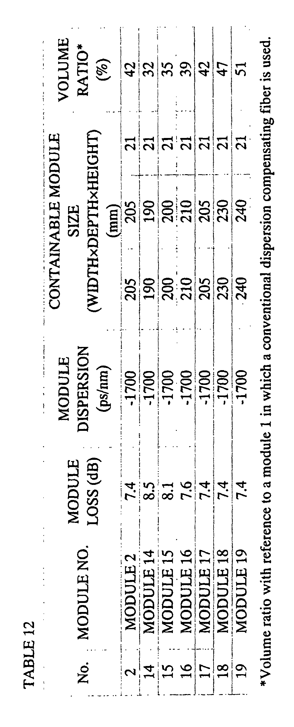
  • a characteristics for a module of the dispersion compensating fiber are shown in TABLE 12 under condition that a module is formed by winding these dispersion compensating fiber in a small reel of which cylinder diameter is 80 mm by 40 g of winding tension and connecting a 1.3 ⁇ m band zero-dispersion single-mode optical fiber with connecters to both ends thereof. Also, these module loss wavelength characteristics are shown in FIG. 7.
  • the module which uses the dispersion compensating fibers of No. 14 and No. 15 is small with compared to conventional modules if it is wound in a small reel of which cylinder diameter is 80 mm, the module loss is deteriorated. Also, according to the TABLE 7, in particular, it is understood that the loss deterioration in a long wavelength band is conspicuous. It is understood that although the module loss is not deteriorated in the module for the dispersion compensating fiber in which a dispersion compensating fiber No. 18 of which outer diameter of the cladding is 100 ⁇ m or greater, the module is not small sufficiently.
  • the outer diameter of the cladding should preferably be 80 ⁇ m to 100 ⁇ m.
  • dispersion compensating fibers with a W-type profile shown in FIG. 1(c) are produced according to a commonly known method such as a VAD method, an MCVD method, or a PCVD method. Under this condition, production is made such that ⁇ 1, ⁇ 2, ⁇ 3, b/a, c/b, a core radius, a diameter of the cladding, Young's modulus and thickness of the primary coating layer, and Young's modulus and thickness of the secondary coating layer are constant as shown in the TABLE 13.
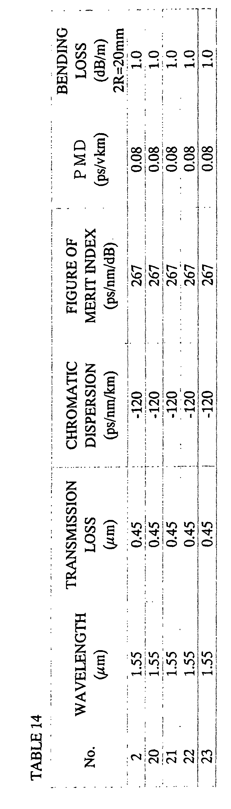
  • the surface an adhesive property was varied in a range of 0.1 to 12 gf/mm by varying an atmospheric oxygen density during a drawing operation in a range of 0.1 % to several percents when an ultraviolet-ray-curable resin is hardened.
  • a dispersion compensating fibers in No. 2, No. 20 to No. 22 are embodiments for the optical fiber according to the present invention.
  • the dispersion compensating fiber No. 23 is produced for a purpose of comparison.
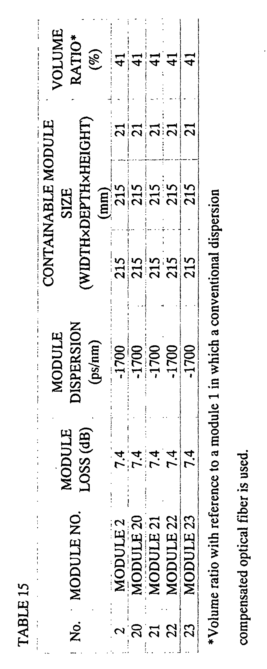
  • Optical characteristics for a module of the dispersion compensating fiber and module size are shown in TABLE 15 under condition that a module is formed by winding these dispersion compensating fiber in a small reel of which cylinder diameter is 80 mm by 40 g of winding tension and connecting a 1.3 ⁇ m band zero-dispersion single-mode optical fiber with connecters to both ends thereof. Also, temperature characteristics for the module loss of these modules are shown in FIG. 8.
  • the optical characteristics and the module size are identical.
  • the deterioration of the module loss under a low temperature condition is great according to an increase in a value of the surface an adhesive property.
  • the module for the dispersion compensating fiber should have stable optical characteristics against a various circumstance temperature. In general, it is required that the fluctuation of the module loss should vary with in ⁇ 0.5 dB or lower under condition a usage temperature range is -5 °C to +75 °C.
  • the surface an adhesive property should be 10 gf/mm or lower. More preferably, it should be 1 gf/mm or lower.
  • a dispersion compensating fibers with a W-type profile shown in FIG. 1(c) is produced according to a commonly known method such as a VAD method, an MCVD method, or a PCVD method. Under such a condition, they are produced such that values such as ⁇ 1, ⁇ 2, ⁇ 3, b/a, c/b, and a core radius are made so as to be shown in a TABLE 16. Under such a condition, although an outer diameter of the cladding is constant, the thickness of the coating layer in each layer and the Young's modulus were varied.
  • a dispersion compensating fibers in No. 2, No. 24, and No. 28 are embodiments for the optical fiber according to the present invention.
  • the dispersion compensating fibers No. 25 to No. 27, and No. 29 to No. 32 are produced for a purpose of comparison.
  • the ⁇ 1, ⁇ 2, ⁇ 3, b/a, c/b, and a core radius are constant; therefore, the optical characteristics were identical.
  • a proof test dispersion compensating fiber was performed after drawing process.
  • a constant expansion distortion is applied to an optical fiber in a longitudinal direction of the optical fiber so as to remove a low-strengthstrength part.
  • a strength which is greater than a certain level is required for the dispersion compensating fiber which is used there.
  • No. 26, 27, 31, and 32 were disconnected in several hundreds meters; thus, it was not possible to obtain a sufficient length (for example, approximately 10 km or more) for producing the module. This is because the Young's modulus of the secondary coating layers in No. 26, No. 27 is low and there is a lack of strength for enduring the expansion distortion in the No. 31, 32 of which secondary coating layers are thin.
  • Optical characteristics for a module of the dispersion compensating fiber and module size are shown in TABLE 18 under condition that a module is formed by winding these dispersion compensating fibers which has a necessary fiber length by the screening test in a small reel of which cylinder diameter is 80 mm by 40 g of winding tension and connecting a 1.3 ⁇ m band zero-dispersion single-mode optical fiber with connecters to both ends thereof. Also, the loss wavelength characteristics for these modules are shown in FIG. 9.
  • the module loss is deteriorated in a long wavelength band in the module in which the dispersion compensating fibers No. 25, 29, and 30 are used. This is because the Young's modulus in the primary coating layer which serves as an absorbing layer is high in No. 25. Also, this is because the loss is deteriorated because an influence of a side pressure reaches at the core section via the cladding because the primary coating layer is thin in No. 29, 30.
  • the Young's modulus in the primary coating layer should be 0.15 kgf/mm 2 or lower
  • the Young's modulus in the secondary coating layer should be 50 kgf/mm 2 or higher
  • the thickness of the secondary coating layer should be 15 ⁇ m to 30 ⁇ m.
  • Dispersion compensating fibers with a W-type profile shown in FIG. 1B or with a W-type profile with ring as shown in FIG. 1C are produced according to a commonly known method such as a VAD method, an MCVD method, or a PCVD method Under such a condition, they are produced such that values such as ⁇ 1, ⁇ 2, ⁇ 3, b/a, c/b, and a core radius are made so as to be shown in a TABLE 19.
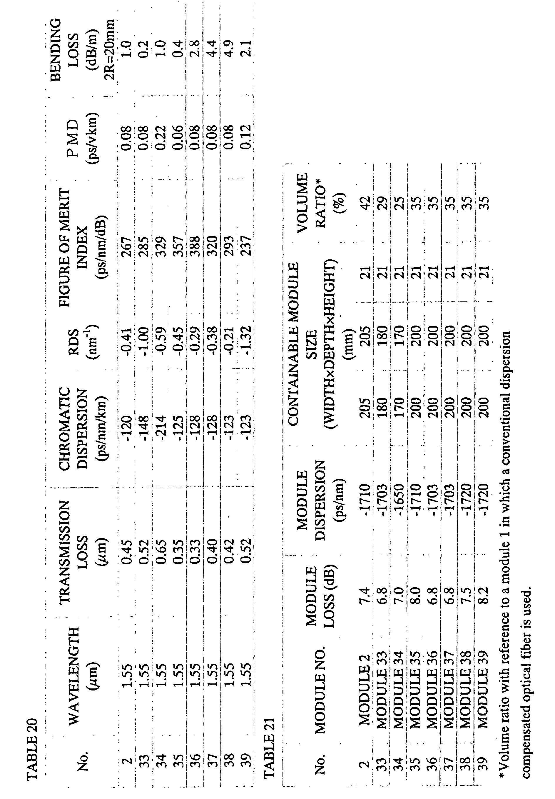
  • a dispersion compensating fibers in No. 2, No. 33 to No. 37 are embodiments for the optical fiber according to the present invention.
  • the dispersion compensating fibers No. 38 and No. 39 are produced for a purpose of comparison.
  • a value for an RDS which is an index for indicating a performance of the dispersion slope compensation was 0.0017 nm -1 to 0.0107 nm -1 .
  • a dispersion compensating fiber No. 33 is a dispersion compensating fiber for compensating a an accumulated dispersion of NZ-DSF.
  • a characteristics for a module of the dispersion compensating fiber are shown in TABLE 21 under condition that a module is formed by winding these dispersion compensating fiber in a small reel of which cylinder diameter is 80 mm by 40 g of winding tension and connecting a 1.3 ⁇ m band zero-dispersion single-mode optical fiber with connecters to both ends thereof.
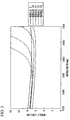
  • a dispersion curve is shown in FIG. 10 under condition a dispersion compensation is performed by using a module for the dispersion compensating fiber which is produced by using the dispersion compensating fibers No. 2, 34, 35, 38, and 39.
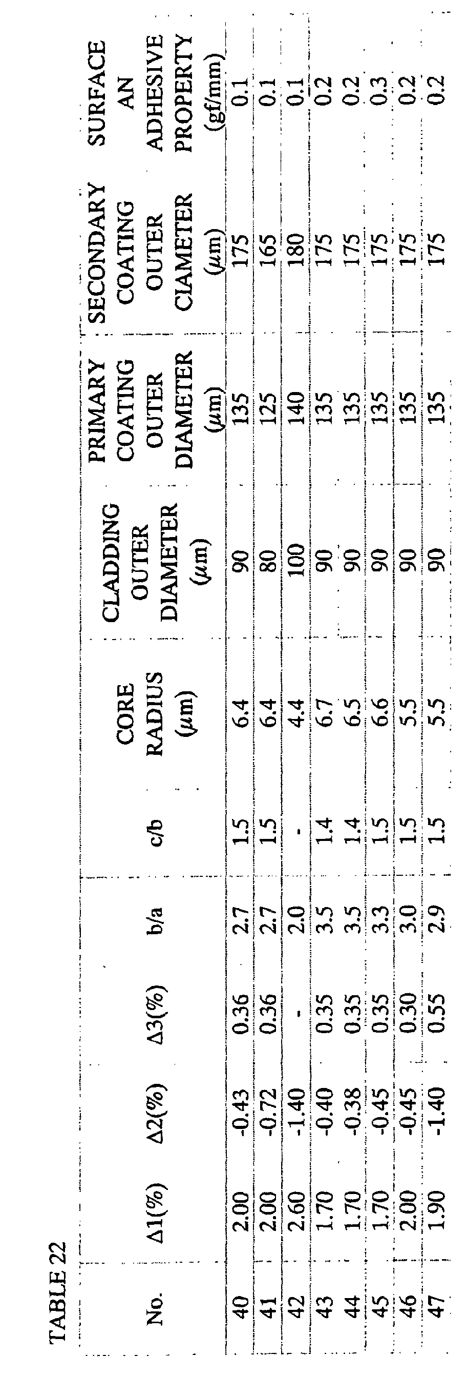
  • Dispersion compensating fibers with a W-type profile shown in FIG. 1(b) or with a W-type profile with ring as shown in FIG. 1(c) are produced according to a commonly known method such as a VAD method, an MCVD method, or a PCVD method Under such a condition, they are produced such that values such as ⁇ 1, ⁇ 2, ⁇ 3, b/a, c/b, and a core radius are made so as to be shown in a TABLE 22.
  • dispersion compensating fibers in No. 40 to No. 45 are embodiments for the optical fiber according to the present invention.
  • the dispersion compensating fibers No. 46 and No. 47 are produced for a purpose of comparison.
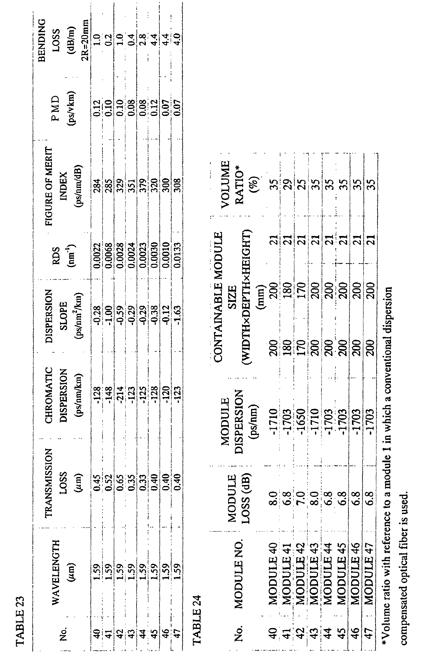
  • These dispersion compensating fibers are fibers for compensating the residual dispersion in an L-band (wavelength 1.565 ⁇ m to 1.625 ⁇ m) of the transmission fiber; therefore, the measurement wavelength was set at 1.59 ⁇ m.
  • a value for an RDS which is an index for indicating a performance of the dispersion slope compensation was 0.0010 nm -1 to 0.0133 nm -1 .
  • a dispersion compensating fiber No. 41 is a dispersion compensating fiber for compensating a wavelength-dispersion compensating fiber of NZ-DSF.
  • a characteristics for a module of the dispersion compensating fiber are shown in TABLE 24 under condition that a module is formed by winding these dispersion compensating fiber in a small reel of which cylinder diameter is 80 mm by 40 g of winding tension and connecting a 1.3 ⁇ m band zero-dispersion single-mode optical fiber with connecters to both ends thereof.
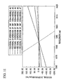
  • a dispersion curve is shown in FIG. 11 under condition a dispersion compensation is performed by using a module for the dispersion compensating fiber which is produced by using the dispersion compensating fibers No. 42, 44, 45, 46, and 47.
  • the present invention it is possible to contain it in a small module with compared to a conventional module for a dispersion compensating fiber in which a module loss is low, the PMD is low, and there is not an increase in a loss which is caused by the bending loss even if it is wound in a small reel.
  • a dispersion compensating fiber which is suitable for the S-SMF and the NZ-DSF.
  • a module for a dispersion compensating fiber in which there is not an outstanding increase in a loss which is caused by a micro-bend characteristics in a long wavelength band, it is possible to contain in a small module with compared to a conventional module for a dispersion compensating fiber, and there is a stable temperature characteristics such as ⁇ 0.5 dB or lower module loss in an ordinary operating temperature range (-5°C to +70°C).

Landscapes

  • Physics & Mathematics (AREA)
  • Chemical & Material Sciences (AREA)
  • Dispersion Chemistry (AREA)
  • General Physics & Mathematics (AREA)
  • Optics & Photonics (AREA)
  • Optical Communication System (AREA)
  • Optical Fibers, Optical Fiber Cores, And Optical Fiber Bundles (AREA)
  • Laminated Bodies (AREA)

Abstract

A dispersion compensating fiber which does not cause an increase in a loss if it is wound in a small reel and has a stable temperature characteristics is provided, wherein, in a wavelength range from dispersion compensating fiber1.53 to 1.63 mu m, a bending loss with a 20 mm bending diameter is 5 dB/m or lower, a chromatic dispersion is -120 ps/nm/km or lower, a cut-off wavelength under a usage condition is 1.53 mu m or lower, an outer diameter of the cladding is 80 to 100 mu m, an outer diameter of a coating is 160 to 200 mu m, and a an adhesive property of a surface of a coating resin is 10 gf/mm or lower. <IMAGE>

Description

This is a National Stage entry of International Application PCT/JP03/03004, with an international filing date of March 13, 2003, which was published under PCT Article 21(2) in Japanese, and the disclosure of which is incorporated herein by reference. Further, International Application PCT/JP03/03004 is based on Japanese Patent Application No. 2002-069077 and 2003-057013, filed in Japan on March 13, 2002 and March 4, 2003, respectively, the disclosures of which are incorporated herein by reference.
TECHNICAL FIELD
The present invention relates to a dispersion compensating fiber which compensates a chromatic dispersion for a 1.3 µm band zero-dispersion single-mode fiber (Standard Single-mode Fiber, hereinafter called an "S-SMF" for short) which has a zero-dispersion wavelength in 1.3 µm band or a non-zero dispersion shift fiber (Non-Zero Dispersion Shifted Fiber, hereinafter called as "NZ-DSF" for short. In particular, the present invention relates to a dispersion compensating fiber in which there are few deterioration in characteristics even if it is formed to be a module by winding in a small reel.
BACKGROUND ART
In general, if a transmission distance for an optical fiber transmission path is formed to be long, a transmission speed is made to be high, and a number of a wavelength multiplication increases, there are a problems such as a transmission loss, an accumulated chromatic dispersion, and a polarization mode dispersion (Polarization Mode Dispersion, hereinafter called as "PMD" for short). It is possible to compensate the transmission loss by realizing an erbium-doped fiber amplifier. Next problem is an accumulated chromatic dispersion. A relationship between a transmission speed and an allowable chromatic dispersion is shown in FIG. 3. It is possible to compensate this accumulated chromatic dispersion by a module in which a dispersion compensating fiber, etc. is used.
By the way, the S-SMF is commonly used all over the world presently. If a transmission for 1.55 µm band is performed by using this optical fiber network, a chromatic dispersion of approximately +17 ps/nm/km is generated in this 1.55 µm band. Therefore, if a signal is transmitted by using this optical fiber, the transmission characteristics deteriorates greatly by an influence of the accumulated chromatic dispersion in a long distance transmission. Also, although an NZ-DSF which has a smaller chromatic dispersion in 1.55 µm band than in the S-SMF is installed mainly for a long distance transmission path, it is necessary to compensate the chromatic dispersion which is accumulated on the transmission path.
Furthermore, at present, a wavelength division multiplexing (Wavelength Division Multiplexing, hereinafter called as "WDM" for short) has been developed along with an increase in a transmission capacity; thus, the WDM transmission has already been realized practically in a lot of transmission paths. It is necessary to reduce the chromatic dispersion which is allowable over an entire wavelength band which is used in the WDM transmission. Therefore, it is necessary to compensate not only the chromatic dispersion but also a dispersion slope. A transmission optical fiber, a dispersion compensating fiber, and a residual dispersion characteristics after compensating the dispersion are shown in FIG. 4. A code for a dispersion slope of the dispersion compensating fiber is opposite to a code for a dispersion slope for a transmission optical fiber, there is a case in which a residual dispersion may be small in a wide range of band. An RDS is named for an index for indicating a performance for compensating this dispersion slope. The RDS (RDS; Relative Dispersion Slope) is a ratio of a dispersion slope with reference to the chromatic dispersion. RDS can be shown in a following formula (1) under condition that D indicates the chromatic dispersion and S indicates the dispersion slope. RDS = S/D
In order to reduce the residual dispersion in a wide range of band, it is necessary to adapt a value which has an opposite code of a dispersion against the chromatic dispersion of the transmission optical fiber such that the RDS is as close as possible.
For such a dispersion compensating fiber, for example, Japanese Unexamined Patent Application, First Publication No. Hei 6-11620 discloses a technology for a dispersion compensating fiber which has a chromatic dispersion which is -20 ps/nm/km or lower for compensating the chromatic dispersion in 1.55 µm band in an S-SMF which has a zero-dispersion wavelength in the wavelength 1.3 µm band. Also, Japanese Unexamined Patent Application, First Publication No. 11-95056 discloses a technology for a dispersion compensating fiber in which a dispersion slope is reduce while reducing a connection loss such that an absolute value for the chromatic dispersion per a unit length is increased.
Also, Japanese Unexamined Patent Application, First Publication No. Hei 8-136758 discloses a technology for a dispersion compensating fiber in which the dispersion slope is minus such that the chromatic dispersion is -100 ps/nm/km or lower.
On the other hand, Japanese Unexamined Patent Application, First Publication No. Hei 8-54546 discloses a small-diameter dispersion compensating fiber which has a primary coating layer of which Young's modulus is 0.1 kgf/mm2 on an outer periphery of an optical fiber bare line (cladding) of which outer diameter is smaller than 125 µm and has a secondary coating layer of which Young's modulus is 150 kgf/mm2 or greater on an outer periphery of the primary coating layer in an optical fiber which has a coating structure shown in FIG. 2. In a sixth embodiment of this Japanese Unexamined Patent Application, First Publication No. Hei 8-54546, a small-diameter dispersion compensating fiber is disclosed which has 60 µm cladding, 160 µm coating, and -80.0 ps/nm/km.
Also, Japanese Unexamined Patent Application, First Publication No. Hei 10-115725 discloses a technology for a dispersion compensating fiber which is connected to an optical fiber which has a chromatic dispersion in a transmission wavelength and compensates the above explained chromatic dispersion so as substantially to eliminate the chromatic dispersion in an entire transmission system in the transmission wavelength band. Also, Japanese Unexamined Patent Application, First Publication No. Hei 10-115725 discloses a technology for a dispersion compensating fiber for reducing the chromatic dispersion in an entire transmission system in the transmission wavelength as close as zero which has a multi-layer structure such as at least two layers or more which comprises a core which is formed by a silica glass, a cladding which is formed by a silica glass on an outer periphery of the core, and a coating layer which is formed by a plastic resin on an outer periphery of the cladding such that an outer diameter is smaller than 250 µm, the coating layer has 20 µm thickness or greater, and an outer layer which has a Young's modulus which is higher than that of an inner layer. A small-diameter dispersion compensating fiber is disclosed in this Japanese Unexamined Patent Application, First Publication No. Hei 10-115725 and in embodiments in a specification of US Patent No. 5,887,104 such that a diameter of an outer cladding is 60 µm to 125 µm, an outer diameter of coating is 110 µm to 250 µm, and the chromatic dispersion is approximately -105 ps/nm/km.
Also, it is reported, in a B-13-4, p-585, thesis titled as "Small Dispersion compensating fiber For Compensating Dispersion", 1999 General Conference, The Institute Of Electronics, Information And Communication Engineers, by Naoto Ogawa et al, that there is not a problem with regards to an increase in the loss due to a side pressure and strength point of view if a proto-type for a small-diameter dispersion compensating fiber is produced in which a chromatic dispersion is -102 ps/nm/km to -110 ps/nm/km, an outer diameter of a cladding is 90 µm to 125 µm, and an outer diameter of coating layer is 150 µm to 185 µm.
Such a dispersion compensating fiber is formed to be a module by disposing in a casing for winding a coil of which length is 1/5 to 1/7 of the transmission optical fiber. Although, when an accumulated dispersion in the transmission optical fiber of which length is approximately 120 km is compensated by a module of a dispersion compensating fiber, a necessary length for the dispersion compensating fiber is approximately 20 km; thus, it is necessary to wind a very long dispersion compensating fiber.
However, it is preferable that a size of the module should be constant with regardless to a necessary amount for compensating the dispersion. Even if an absolute amount of the dispersion which is compensated is great, it is necessary to wind the dispersion compensating fiber as long as possible in a small case. Furthermore, it is preferable that this module for the dispersion compensating fiber should be as small as possible so as to form a small transmission device.
A volume of the module depends on a volume for winding the dispersion compensating fiber. Such a winding volume is indicated by a product for a cross sectional area which includes a coating and a fiber length of the dispersion compensating fiber.
Therefore, it is effective if dispersion compensating fiber is formed such that its diameter should be as small as possible for forming a small module as disclosed in the Japanese Unexamined Patent Application, First Publication No. Hei 8-54546, Japanese Unexamined Patent Application, First Publication No. Hei 10-115725, or US Patent No. 5,887,104.
The development for the dispersion compensating fiber has been made such that an absolute value for the chromatic dispersion per a unit length unless the transmission loss is deteriorated, and an optical characteristic and reliability are not deteriorated; thus, the diameter of the optical fiber should be as small as possible in an allowable range. However, the technology which are disclosed in the above mentioned publication and a report by an institute was not sufficient for realizing a small module while restricting an increase of a loss which is caused by a bending loss over an entire range of the operating wavelength.
DISCLOSURE OF THE INVENTION
The present invention was made for solving the above mentioned problems. The present invention was invented so as to realize an stable temperature characteristics with a low loss and a low PMD in a dispersion compensating fiber such that a volume ratio should be less than a half with reference to a module of the conventional dispersion compensating fiber. An object of the present invention is to provide a dispersion compensating fiber such that a fluctuation of a module loss should be within ± 0.5 dB in a temperature range (-5 °C to +70°C) which is used ordinarily even if a module of the dispersion compensating fiber is produced.
In order to solve the above problems, a first aspect of the present invention is a dispersion compensating fiber in which, in at least a wavelength which is selected from 1.53 µm to 1.63 µm, a bending loss is 5 dB/m or lower when it is wound by a 20 mm bending diameter, a chromatic dispersion is -120ps/nm/km or lower, an absolute value of the chromatic dispersion per a unit loss is 200 ps/nm/dB or higher, a cut-off wavelength for used length and used condition is 1.53 µm or lower, an outer diameter of a cladding is 80µm to 100µm, an outer diameter of coating is 160µm to 200µm, and a an adhesive property of a surface of a coating resin is 10gf/mm or lower.
By doing this, it is possible to realize a dispersion compensating fiber in which, even if it is wound in a small reel, a module loss is low, there is not an increase of a loss which is caused by a bending loss, there is not an outstanding increase of a loss which is caused by a bending loss in a long wavelength band. Thus, it is possible to contain the dispersion compensating fiber in a smaller module with reference to a conventional module of the dispersion compensating fiber. Even if a module for a dispersion compensating fiber by winding it in a small coil, it is possible to realize a module for the dispersion compensating fiber which has a stable temperature characteristics such that a fluctuation of the module loss is ± 0.5 dB or lower in an ordinary usage temperature range (-5 °C to + 70°C).
The adhesive property is measured by the following method. First, the optical side dancer roll. Then, it is introduced into a receiving roll through a first fixed roll, a moving roll and a second fixed roll, and is set to a tension pickup between the moving roll and the second fixed roll. The optical fiber passed through the receiving roll is mounted on a winding roll through a winding side dancer roll similar to the transmitting side dancer roll. Then the winding roll is rotated to impart a fixed tension to the optical fiber. The tension pickup detects the moving quantity of a detecting roll by the tension of the optical fiber to detect the tension, and displays and records it on a monitor. In this case, since the tension change added to the optical fiber becomes a value according to the surface tackiness, the surface tackiness of the optical fiber can be easily and quantitively measured and evaluated.
A second aspect of the present invention is a dispersion compensating fiber in which the an adhesive property of the surface of the coating resin of the dispersion compensating fiber is 1gf/mm or lower.
By doing this, it is possible to realize a dispersion compensating fiber which has a further stable loss characteristics to a surrounding temperature.
A third aspect of the present invention is a dispersion compensating fiber in which a Young's modulus of a primary coating layer which is disposed on an outer periphery of the cladding is 0.15kgf/mm2, a thickness of the primary coating layer is 20 µm to 30 µm, a Young's modulus of a secondary coating layer which is disposed on an outer periphery of the primary coating layer is 50kgf/mm2, and a thickness of the secondary coating layer is 15 µm to 30 µm.
By doing this, it is possible to realize a dispersion compensating fiber while maintaining a high reliability in which, even if it is wound in a small reel, a module loss due to the winding operation is low, in particular, there is not an outstanding increase of a loss which is caused by a micro bend characteristics in a long wavelength band band. Thus, it is possible to contain the dispersion compensating fiber in a smaller module with reference to a conventional module of the dispersion compensating fiber.
A fourth aspect of the present invention is a dispersion compensating fiber which comprises at least a core and a cladding which is disposed on an outer periphery of the core. In this aspect of the present invention, a refractive index difference of the center core section with reference to the cladding is +1.6% to +2.6%, a refractive index difference of the intermediate core section with reference to the cladding is -0.30% to -1.4%, a refractive index difference of the ring core section with reference to the cladding is +0.30% to +1.0%, a ratio of a radius of the intermediate core section with reference to a radius of the center core section is 1.5 to 3.5, a ratio of a radius of the intermediate core section with reference to a radius of the ring core section is 1.2 to 2.0, and a radius of the core is 4 µm to 8 µm.
By doing this, it is possible to realize a dispersion compensating fiber in which, even if it is wound in a small reel, a module loss is low, there is not an outstanding increase of a loss which is caused by a bending loss in a long wavelength band. Thus, it is possible to contain the dispersion compensating fiber in a smaller module with reference to a conventional module of the dispersion compensating fiber.
Here, even if refractive index differences in each of these layers, a ratio of a radius of an intermediate core section with reference to a radius of the center core section, and a ratio of a radius of the ring core section with reference to the radius of the intermediate core section are within these ranges, it is not certain whether or not it is possible to obtain the dispersion compensating fiber of the present invention. From this point of view, in the present invention, it is intended to specify a structural parameter and a characteristic value of the dispersion compensating fiber.
A fifth aspect of the present invention is a dispersion compensating fiber which comprises at least a core which is formed at least the center core section and the intermediate core section, and a cladding, such that a refractive index difference of the center core section with reference to the cladding is +1.6% to +2.6%;a refractive index difference of the intermediate core section with reference to the cladding is -0.30% to -1.4%;a ratio of a radius of the intermediate core section with reference to a radius of the center core section is 1.5 to 3.5;a ratio of a radius of the intermediate core section with reference to a radius of the ring core section is 1.2 to 2.0, and a radius of the core is 4µm to 8 µm.
By doing this, it is possible to realize a dispersion compensating fiber in which, even if it is wound in a small reel, a module loss is low, there is not an outstanding increase of a loss which is caused by a bending loss in a long wavelength band band. Thus, it is possible to contain the dispersion compensating fiber in a smaller module with reference to a conventional module of the dispersion compensating fiber.
Here, even if refractive index differences in each of these layers, and a ratio of a radius of an intermediate core section with reference to a radius of the center core section are within these ranges, it is not certain whether or not it is possible to obtain the dispersion compensating fiber of the present invention. From this point of view, in the present invention, it is intended to specify a structural parameter and a characteristic value of the dispersion compensating fiber.
In a sixth aspect of the present invention, in at least a wavelength which is selected from 1.53 µm to 1.57µm, a quotient which is obtained by dividing the dispersion slope by the chromatic dispersion is 0.0026nm-1 to 0.010 nm-1.
By doing this, it is possible to realize a dispersion compensating fiber in which, even if it is wound in a small reel, a module loss is low, there is not an outstanding increase of a loss which is caused by a bending loss in a long wavelength band. Thus, it is possible to contain the dispersion compensating fiber in a smaller module with reference to a conventional module of the dispersion compensating fiber. Compatibly, the RDS in 1.53 µm to 1.57µm is 0.0026 nm-1 to 0.010nm-1, it is possible to realize a dispersion compensating fiber which is suitable for the S-SMF which has an RDS typically such as 0.0034 nm-1 in 1.55µm and an NZ-DSF which has a typical RDS such as 0.007 nm-1 to 0.010 nm-1.
In a seventh aspect of the present invention, , in at least a wavelength which is selected from 1.53 µm to 1.57µm, a quotient which is obtained by dividing the dispersion slope by the chromatic dispersion is 0.0026nm-1 to 0.0041 nm-1.
By doing this, it is possible to realize a dispersion compensating fiber in which, even if it is wound in a small reel, a module loss is low, there is not an outstanding increase of a loss which is caused by a bending loss in a long wavelength band. Thus, it is possible to contain the dispersion compensating fiber in a smaller module with reference to a conventional module of the dispersion compensating fiber. Compatibly, the RDS is 0.0026nm-1 to 0.0041 nm-1; thus, is it possible to realize a dispersion compensating fiber which is suitable for the S-SMF which has typically an RDS such as 0.0034 nm-1.
In an eighth aspect of the present invention, in at least a wavelength which is selected from 1.57 µm to 1.63µm, a quotient which is obtained by dividing the dispersion slope by the chromatic dispersion is 0.0022nm-1 to 0.010 nm-1.
By doing this, it is possible to realize a dispersion compensating fiber in which, even if it is wound in a small reel, a module loss is low, there is not an outstanding increase of a loss which is caused by a bending loss in a long wavelength band. Thus, it is possible to contain the dispersion compensating fiber in a smaller module with reference to a conventional module of the dispersion compensating fiber. Compatibly, the RDS in 1.57 µm to 1.63µm is 0.0022 nm-1 to 0.010nm-1, it is possible to realize a dispersion compensating fiber which is suitable for the S-SMF which has an RDS typically such as 0.0029 nm-1 in 1.59 µm and an NZ-DSF which has a typical RDS such as 0.005 nm-1 to 0.010 nm-1.
In a ninth aspect of the present invention, in at least a wavelength which is selected from 1.57 µm to 1.63µm, a quotient which is obtained by dividing the dispersion slope by the chromatic dispersion is 0.0022nm-1 to 0.0035 nm-1.
By doing this, it is possible to realize a dispersion compensating fiber in which, even if it is wound in a small reel, a module loss is low, there is not an outstanding increase of a loss which is caused by a bending loss in a long wavelength band. Thus, it is possible to contain the dispersion compensating fiber in a smaller module with reference to a conventional module of the dispersion compensating fiber. Compatibly, the RDS is 0.0026nm-1 to 0.0035 nm-1 in 1.57 µm to 1.63 µm; thus, is it possible to realize a dispersion compensating fiber which is suitable for the S-SMF which has typically an RDS such as 0.0029 nm-1 in 1.59 µm.
Brief Description of Drawings
These and other features, aspects, and advantages of the present invention will become better understood with reference to the following description and accompanying drawings, which should not be read to limit the invention in any way, in which:
  • FIGS. 1A, 1B, and 1C are views for showing an example for refractive index profile of the dispersion compensating fiber according to the present invention.
  • FIG. 2 is a cross section for showing a structure for a coating layer of the dispersion compensating fiber of the present invention.
  • FIG. 3 is a graph for showing a conventional relationship for a transmission speed and an allowable chromatic dispersion.
  • FIG. 4 is a graph which shows a transmission optical fiber, a dispersion compensating fiber, and a residual dispersion characteristic after compensating the dispersion.
  • FIG. 5 is a graph for showing a wavelength dependence of insertion loss for a module of a dispersion compensating fiber which uses a dispersion compensating fiber in which a bending loss is varied.
  • FIG. 6 is a graph for showing a temperature characteristics for a module of a dispersion compensating fiber which uses a dispersion compensating fiber in which a bending loss is varied.
  • FIG. 7 is a graph for showing a wavelength dependence of insertion loss for a module of a dispersion compensating fiber which uses a dispersion compensating fiber of which outer diameter of the cladding loss is varied.
  • FIG. 8 is a graph for showing a loss wavelength characteristics for a module of a dispersion compensating fiber which uses a dispersion compensating fiber in which a surface an adhesive property is varied.
  • FIG. 9 is a graph for showing a loss wavelength characteristics for a module of a dispersion compensating fiber which uses a dispersion compensating fiber in which a Young's modulus of a coating layer and a thickness of the coating are varied.
  • FIG. 10 is a graph which shows a residual dispersion characteristics for a case in which an accumulated chromatic dispersion is compensated in S-SMF100km by a module for the dispersion compensating fiber which has a different RDS.
  • FIG. 11 is a graph which shows a residual dispersion characteristics for a case in which an accumulated chromatic dispersion is compensated in S-SMF100km by a module for the dispersion compensating fiber which has a different RDS.
  • Best Mode for Carrying Out the Invention
    The present invention is explained in detail as follows.
    An example for a refractive index distribution of the dispersion compensating fiber according to the present invention is shown in FIGS. 1(a), (b), (c).
    In FIGS. 1(a), (b), reference numeral 1a indicates a center core section. Reference numeral 1b indicates an intermediate core section which is disposed on an outer periphery of the center core section 1a. Reference numeral 2 indicates a cladding which is disposed on an outer periphery of the intermediate core section 1b. Also, in FIG. 1(c), reference numeral 1a indicates a center core section. Reference numeral 1b indicates an intermediate core section which is disposed on an outer periphery of the center core section 1a. Reference numeral 1c indicates a ring core section which is disposed on an outer periphery of the intermediate core section 1b. Reference numeral 2 indicates cladding which is disposed on an outer periphery of the ring core section 1c.
    In FIGS. 1(a), (b), (c), A letter a indicates a radius of the center core section 1a. A letter b indicates a radius of the center core section 1b. A letter c indicates a radius of the ring core section 1c. A refractive index difference of the center core section 1a with reference to the cladding 2 is indicated by Δ1. A refractive index difference of the intermediate core section 1b with reference to the cladding 2 is indicated by Δ2. A refractive index difference of the ring core section 1c with reference to the cladding 2 is indicated by Δ3.
    The center core section 1a has a refractive index which is greater than the refractive index of the cladding 2. The intermediate core section 1b has a refractive index which is smaller than the refractive index of the cladding 2. The ring core section 1c has a refractive index which is greater than the refractive index of the cladding 2.
    In a first example for the dispersion compensating fiber according to the present invention, a ratio b/a of the radius of the intermediate core section with reference to the radius of the center core section is 1.5 to 3.5, a ratio c/b of the radius of the ring core section with reference to the radius of the intermediate core section is 1.2 to 2.0, a radius of the core is 4 µm to 8µm, a refractive index difference Δ1 of the center core section 1a with reference to the cladding 2 is +1.6 % to +2.6%, a refractive index difference Δ2 of the intermediate core section 1b with reference to the cladding 2 is -0.30% to -1.4%, and a refractive index difference Δ3 of the ring core section 1c with reference to the cladding 2 is +0.30% to +1.0%.
    Also, the dispersion compensating fiber in this example is specified by specific values below in addition to these structures. Such specific values are such that, in at least a wavelength which is selected from 1.53 µm to 1.63 µm, a bending loss is 5 dB/m or lower when it is wound by a 20 mm bending diameter, a chromatic dispersion is -120ps/nm/km or lower, an absolute value of the chromatic dispersion per a unit loss is 200 ps/nm/dB or higher, a cut-off wavelength for used length and used condition is 1.53 µm or lower, an outer diameter of a cladding is 80µm to 100µm, an outer diameter of coating is 160µm to 200µm, and a an adhesive property of a surface of a coating resin is 10gf/mm or lower, more preferably 1 gf/mm or lower. Here, the chromatic dispersion is in a range in which it is possible to realize approximately -300 ps/nm/km or greater from a view point of a range for controlling a refractive index difference and a bending loss. An absolute value for the chromatic dispersion per a unit loss is in a range in which it is possible to realize approximately 500 ps/nm/dB from a view point of a value of the transmission loss.
    A structure of a coating layer of this dispersion compensating fiber is shown in FIG. 2.
    In FIG. 2, reference numeral 1 indicates a core. Reference numeral 2 indicates a cladding which is formed around the core 1. A primary coating layer 3 is formed on an outer periphery of the cladding 2. A secondary coating layer 4 is formed on an outer periphery of the primary coating layer 3. It is preferable that the Young's modulus of the primary coating layer should be 0.15 kgf/mm2 or lower. Also, it is preferable that the Young's modulus of the secondary coating layer should be 50 kgf/mm2 or greater.
    A main role for each of the coating layer is such that the primary coating layer serves for a shock-absorbing member so as to contact a surface of a glass member and the secondary coating layer serves for maintaining a strength for an optical fiber. Therefore, it is preferable if both the primary coating layer and the secondary coating layer are thick. However, if both of them are thick, it is not possible to realize a purpose for providing a small module for a dispersion compensating fiber by forming the dispersion compensating fiber in a small radius. Also, if the Young's modulus of the primary coating layer exceeds 0.15 kgf/mm2, an external influence disturbs the optical fiber directly. Consequently, a micro-bend loss, etc. is generated; thus, a transmission loss is deteriorated. Furthermore, is the Young's modulus of the secondary coating layer is less than 50 kgf/mm2, it is not possible to maintain the strength of the optical fiber. These values relates to thickness of each layer. It is preferable that the thickness of the primary coating layer is 20 µm to 30 µm, and the thickness of the secondary coating layer is 15 µm to 30 µm. Therefore, the relationship between these is shown in formulae (2), (3). It is preferable to use a resin of which Young's modulus satisfies conditions in these formulae from a fiber strength point of view. 0.06×10⁻³≦S1×E1≦1.3×10⁻³ 0.3≦S2×E2≦3.0
    Here, S1 indicates a cross sectional area [mm2] for the primary coating layer,, E1 indicates a Young's modulus [kgf/mm2] in the primary coating layer, S2 indicates a cross sectional area [mm2] of the secondary coating layer, E2 indicates a Young's modulus [kgf/mm2] in the secondary coating layer.
    In this dispersion compensating fiber, it is preferable that an outer diameter of the cladding 2 is 80µm to 100µm, and an outer diameter of a coating which is formed by the primary coating layer 3 and the secondary coating layer 4 is 160µm to 200µm.
    If an outer diameter of the cladding 2 exceeds 100µm so as to secure a necessary coating thickness, an outer diameter of coating is inevitably greater; thus, such a condition cannot be consistent with a purpose for providing a small module. On the other hand, if an outer diameter of the cladding 2 is smaller than 80 µm, the cladding thickness is too thin; thus, it is vulnerable to an influence of a micro-bend, etc.; thus, a loss characteristics is deteriorated. Although it is possible to reduce such an influence by increasing the coating thickness, it is necessary to reduce a characteristics such as a bending loss, etc. as long as it is smaller than 80 µm Therefore, it is preferable that the outer diameter of the cladding 2 should be 80 µm or greater.
    Also, it is possible to form a short fiber by increasing an absolute value for the dispersion; thus, it is possible to realize a smaller module. If an outer diameter of a coating which is formed by the primary coating layer 3 and the secondary coating layer 4 exceeds 200 µm, such an effect is not so great. On the other hand, if the outer diameter of the coating is smaller than 160 µm, the thickness of the primary coating layer and the thickness of the secondary coating layer are too thin; thus, it may be more feasible that it will be disturbed by a micro-bend, etc., or a deterioration of a strength in an optical fiber itself may occur.
    Also, if a module for a dispersion compensating fiber is produced by winding a dispersion compensating fiber of which diameter is formed to be small, a temperature characteristics for the module loss is deteriorated because of the surface an adhesive property. It is possible to realize a module for a dispersion compensating fiber which has a stable temperature characteristics such as a ± 0.5 dB or smaller fluctuation of the module loss in an ordinary operating temperature range (-5°C to +70°C) by forming the surface an adhesive property to be 10 gf/mm or smaller, more preferably 1gf/mm or smaller even if a module for a dispersion compensating fiber is produced by winding it on a small coil.
    For a method for reducing such a an adhesive property, methods can be named such as using an ultraviolet-ray-curable resin which contains 1 to 5 wt % of silicone component or forming the ultraviolet-ray-curable resin so as to have an 2 % or lower atmospheric oxygen density which is more preferably 0 %.
    By doing this, it is possible to realize a dispersion compensating fiber which can be contained in a small module in which a module loss is low and there is not an outstanding increase in a loss in a long wavelength band which is caused by the bending loss and the micro-bend characteristics with compared to a conventional module for a dispersion compensating fiber even if it is wound in a small reel. It is possible to realize a module for a dispersion compensating fiber which has a stable temperature characteristics such as a ± 0.5 dB or smaller fluctuation of the module loss in an ordinary operating temperature range (-5°C to +70°C).
    A second example for a dispersion compensating fiber according to the present invention is formed such that, in a W-type refractive index profile as shown in FIGS. 1(a), (b), a ratio b/a of a radius of the intermediate core section with reference to the radius of the center core section is 1.5 to 3.5, a radius of the core is 4 µm to 8 µm, a relative refractive index difference Δ1 of the center core section 1a with reference to the cladding 2 is +1.6 % to +2.6 %, a relative refractive index difference Δ2 of the intermediate core section 1b with reference to the cladding 2 is -0.30 % to -1.4 %.
    Also, the dispersion compensating fiber in this example is specified by specific values below in addition to these structures. Such specific values are such that, in at least a wavelength which is selected from 1.53 µm to 1.63 µm, a bending loss is 5 dB/m or lower when it is wound by a 20 mm bending diameter, a chromatic dispersion is -120ps/nm/km or lower, an absolute value of the chromatic dispersion per a unit loss is 200 ps/nm/dB or higher, a cut-off wavelength for used length and used condition is 1.53 µm or lower, an outer diameter of a cladding is 80µm to 100µm, an outer diameter of coating is 160µm to 200µm, and a an adhesive property of a surface of a coating resin is 10gf/mm or lower, more preferably 1 gf/mm or lower.
    By doing this, it is possible to realize a dispersion compensating fiber which can be contained in a small module in which a module loss is low and there is not an outstanding increase in a loss in a long wavelength band which is caused by the bending loss and the micro-bend characteristics with compared to a conventional module for a dispersion compensating fiber even if it is wound in a small reel.
    Regarding a PMD, it is preferable to be 0.3 ps/vkm orin any one of the above explained first and the second example. More preferably, it is 0.2 ps/vkm lower.
    A PMD is a mode dispersion which is caused because a degeneracy is released by forming a core of a single-mode optical fiber in an oval shape; thus, a group delay difference is generated between a two orthogonal polarization modes. Therefore, the PMD has not been a big problem because it has been possible to ignore the PMD in a conventional communication speed. However, the PMD is a factor for a cause of a transmission characteristics deterioration in a large-capacity optical communication system. A limitation for a transmission distance for the PMD can be represented by a formula (4) below. B·PMD·vL<100
    Here, B indicates a transmission speed [Gb/s] PMD indicates a polarization mode dispersion [ps/vkm] L indicates a fiber length [km] Although a required value for the PMD is different according to the transmission speed and the transmission distance, it is necessary to maintain the PMD as low as possible if a future upgrading operation (for example, an enhancement for the transmission speed) is taken into account for a transmission system.
    A third example for a dispersion compensating fiber according to the present invention is formed such that, in a W-type refractive index profile as shown in FIGS. 1(a), (b), a ratio b/a of a radius of the intermediate core section with reference to the radius of the center core section is 1.5 to 3.5, a radius of the core is 4 µm to 8 µm, a relative refractive index difference Δ1 of the center core section 1a with reference to the cladding 2 is +1.6 % to +2.6 %, a relative refractive index difference Δ2 of the intermediate core section 1b with reference to the cladding 2 is -0.30 % to -1.4 %. A third example for the dispersion compensating fiber according to the present invention is formed such that, in a W-type profile with a ring which is shown in FIG. 1(c), a ratio b/a of the radius of the intermediate core section with reference to the radius of the center core section is 1.5 to 3.5, a ratio c/b of the radius of the ring core section with reference to the radius of the intermediate core section is 1.2 to 2.0, a radius of the core is 4 µm to 8µm, a refractive index difference Δ1 of the center core section 1a with reference to the cladding 2 is +1.6 % to +2.6%, a refractive index difference Δ2 of the intermediate core section 1b with reference to the cladding 2 is -0.30% to -1.4%, and a refractive index difference Δ3 of the ring core section 1c with reference to the cladding 2 is +0.30% to +1.0% Also, the dispersion compensating fiber in this example is specified by specific values below in addition to these structures. Such specific values are such that, in at least a wavelength which is selected from 1.53 µm to 1.57 µm, a bending loss is 5 dB/m or lower when it is wound by a 20 mm bending diameter, a chromatic dispersion is -120ps/nm/km or lower, an absolute value of the chromatic dispersion per a unit loss is 200 ps/nm/dB or higher, a cut-off wavelength for used length and used condition is 1.53 µm or lower, a quotient which is obtained by dividing the dispersion slope by the chromatic dispersion is 0.0026 nm-1 to 0.010 nm-1, an outer diameter of a cladding is 80µm to 100µm, an outer diameter of coating is 160µm to 200µm.
    By using such a dispersion compensating fiber, it is possible to contain it in a small module with compared to a conventional module for a dispersion compensating fiber in which a module loss is low and there is not an outstanding increase in a loss in a long wavelength band which is caused by the bending loss and the micro-bend even if it is wound in a small reel. Typically, it is possible to realize a dispersion compensating fiber which is suitable for the S-SMF which has an RDS typically such as 0.0034 nm-1 in 1.55µm and an NZ-DSF which has a typical RDS such as 0.007 nm-1 to 0.010 nm-1 in 1.55 µm band.
    A fourth example for a dispersion compensating fiber according to the present invention is formed such that, in a W-type refractive index profile as shown in FIGS. 1(a), (b), a ratio b/a of a radius of the intermediate core section with reference to the radius of the center core section is 1.5 to 3.5, a radius of the core is 4 µm to 8 µm, a relative refractive index difference Δ1 of the center core section 1a with reference to the cladding 2 is +1.6 % to +2.6 %, a relative refractive index difference Δ2 of the intermediate core section 1b with reference to the cladding 2 is -0.30 % to -1.4 %. Also, a fourth example for the dispersion compensating fiber according to the present invention is formed such that, in a W-type profile with a ring which is shown in FIG. 1(c), a ratio b/a of the radius of the intermediate core section with reference to the radius of the center core section is 1.5 to 3.5, a ratio c/b of the radius of the ring core section with reference to the radius of the intermediate core section is 1.2 to 2.0, a radius of the core is 4 µm to 8µm, a refractive index difference Δ1 of the center core section 1a with reference to the cladding 2 is +1.6 % to +2.6%, a refractive index difference Δ2 of the intermediate core section 1b with reference to the cladding 2 is -0.30% to -1.4%, and a refractive index difference Δ3 of the ring core section 1c with reference to the cladding 2 is +0.30% to +1.0% Also, the dispersion compensating fiber in this example is specified by specific values below in addition to these structures. Such specific values are such that, in at least a wavelength which is selected from 1.57 µm to 1.63 µm, a bending loss is 5 dB/m or lower when it is wound by a 20 mm bending diameter, a chromatic dispersion is -120ps/nm/km or lower, an absolute value of the chromatic dispersion per a unit loss is 200 ps/nm/dB or higher, a cut-off wavelength for used length and used condition is 1.57 µm or lower, a quotient which is obtained by dividing the dispersion slope by the chromatic dispersion is 0.0022 nm-1 to 0.010 nm-1, an outer diameter of a cladding is 80µm to 100µm, an outer diameter of coating is 160µm to 200µm.
    By using such a dispersion compensating fiber, it is possible to contain it in a small module with compared to a conventional module for a dispersion compensating fiber in which a module loss is low and there is not an outstanding increase in a loss in a long wavelength band which is caused by the bending loss even if it is wound in a small reel. Compatibly, the RDS in 1.57 µm to 1.63 µm is 0.0022 nm-1 to 0.010 nm-1. Therefore, typically, it is possible to realize a dispersion compensating fiber which is suitable for the S-SMF which has an RDS typically such as 0.0029 nm-1 in 1.59µm and an NZ-DSF which has a typical RDS such as 0.005 nm-1 to 0.010 nm-1 and a chromatic dispersion approximate several ps/nm/km in 1.59 µm band.
    Also, it is possible to prevent a deterioration of the module loss due to the deformed winding operation and a deterioration of the PMD by forming a module for a dispersion compensating fiber by winding the above explained dispersion compensating fiber in a reel which has 90 mm of a minimum cylinder diameter at a winding tension between 30 g to 50 g. Also, it is possible to reduce the deterioration of the module loss due to the micro-bend; therefore, it is possible to realize a small module for a dispersion compensating fiber which has a stable characteristics against a vibrating collision and a fluctuation of the temperature.
    Hereinafter, specific examples are shown.
    (Example 1)
    Dispersion compensating fibers are produced with a W-type profile shown in FIG. 1(b) and a W-type profile with a ring shown in FIG. 1(c) according to a commonly known method such as a VAD method, an MCVD method, or a PCVD method. Under such a condition, values such as Δ1, Δ2, Δ3, b/a, c/b, a core radius, a diameter of the cladding, an outer diameter of a primary coating layer, and an outer diameter of a secondary coating layer are made so as to be values shown in a TABLE 1 under condition that an atmospheric oxygen density should be 0.1 % or lower (0.0% when it is displayed) when an ultraviolet-ray-curable resin is hardened while being drawn.
    Here, a dispersion compensating fiber in No. 1 is produced so as to have an outer diameter of the conventional cladding and a coating structure for a purpose of a comparison. The dispersion compensating fibers shown in No. 2 to No. 6 are examples of the optical fiber according to the present invention.
    Figure 00210001
    Optical characteristics for these dispersion compensating fibers are shown in a TABLE 2.
    In these dispersion compensating fiber, values such as Δ1, Δ2, Δ3, b/a, c/b, and a core radius are set to be values shown in the TABLE 1. By doing this, it was possible to increase an absolute value of the chromatic dispersion per a unit length of an optical fiber and decrease the bending loss. Also, a primary coating layer of which Young's modulus is 0.15 kgf/mm2 or lower and a secondary coating layer of which Young's modulus is 50 kgf/mm2 or higher are formed on an outer periphery of the cladding of which outer diameter is 80 µm to 100 µm.
    The outer diameter of the coating of this dispersion compensating fiber is as narrow as 160 µm to 200 µm; thus, it is possible to form a small module thereby. Also, an optical characteristics for a module of the dispersion compensating fiber and module size are shown in TABLE 3 under condition that a module is formed by winding these dispersion compensating fiber in a small reel of which cylinder diameter is 80 mm by 40 g of winding tension and connecting a 1.3 µm band zero-dispersion single-mode optical fiber with connecters to both ends thereof. These modules for the dispersion compensating fiber serve for S-SMF 100 km compensation.
    Figure 00230001
    According to the TABLE 3, it is understood that a dispersion compensating fiber is realized in which a module loss is low, and there is not an increase in a loss which is caused by a bending loss even if it is wound in a small reel and it is possible to contain thereof in a small module of which volume ratio is 50 % or lower with compared to a conventional module for a dispersion compensating fiber.
    (Example 2)
    Four variations of dispersion compensating fibers with a W-type profile shown in FIG. 1C are produced according to a commonly known method such as a VAD method, an MCVD method, or a PCVD method. Under such a condition, values such as Δ1, Δ2, Δ3, b/a, c/b, and a core radius are made so as to be values shown in a TABLE 4 under condition that an atmospheric oxygen density should be 0.1 % or lower (0.0% when it is displayed) when an ultraviolet-ray-curable resin is hardened while being drawn.
    Here, a dispersion compensating fibers in No. 7 to No. 9 are produced so as to have conventional dispersion characteristics for a purpose of a comparison. The dispersion compensating fiber shown in No. 2 is an example of the optical fiber according to the present invention.
    Figure 00250001
    Optical characteristics for these dispersion compensating fibers are shown in a TABLE 5.
    In these dispersion compensating fiber, values such as Δ1, Δ2, Δ3, b/a, c/b, and a core radius are set to be values shown in the TABLE 4. By doing this, values for the chromatic dispersion were varied without changing the bending loss. The outer diameter of the cladding, Young's modulus and thickness of the primary coating layer, and Young's modulus and thickness of the secondary coating layer are the same.
    A module is formed by winding these dispersion compensating fiber in a small reel of which cylinder diameter is 80 mm by 40 g of winding tension and connecting a 1.3 µm band zero-dispersion single-mode optical fiber with connecters to both ends thereof. The module dispersion is -1700 ps/nm which is equivalent for S-SMF 100km compensation. Optical characteristics of the module of the dispersion compensating fiber and the module size are shown in TABLE 6 when they are produced.
    Figure 00270001
    According to the TABLE 6, it is understood that a module for a dispersion compensating fiber which uses a dispersion compensating fiber No. 7 of which chromatic dispersion is -90ps/nm/km has 47 % of volume ratio with reference to a conventional module. Dispersion compensating fiber No. 8 with -83 ps/nm/km and a dispersion compensating fibers No. 8 and No. 9 which use a dispersion compensating fiber No. 9 with -77 ps/nm/km have 50 % of volume ratio or higher with reference to the conventional module; thus, it is understood that a smaller device is not realized sufficiently. According to these results, it is understood that it is necessary that the absolute value for the chromatic dispersion should be 120 ps/nm or higher (-120 ps/nm/km or lower) at least.
    (Example 3)
    Five variations of dispersion compensating fibers with a W-type profile shown in FIG. 1B or with a W-type profile with ring as shown in FIG. 1C are produced according to a commonly known method such as a VAD method, an MCVD method, or a PCVD method Under such a condition, values such as Δ1, Δ2, Δ3, b/a, c/b, a core radius, a diameter of the cladding, an outer diameter of a primary coating layer, and an outer diameter of a secondary coating layer are made so as to be values shown in a TABLE 1 under condition that an atmospheric oxygen density should be 0.1 % or lower (0.0% when it is displayed) when an ultraviolet-ray-curable resin is hardened while being drawn.
    Here, a dispersion compensating fibers in No. 12 to No. 13 are produced so as to have conventional dispersion characteristics for a purpose of a comparison. The dispersion compensating fiber shown in No. 2, No. 10, and No. 11 are examples of the optical fiber according to the present invention.
    Figure 00290001
    Optical characteristics for these dispersion compensating fibers are shown in a TABLE 8.
    In these dispersion compensating fiber, values such as Δ1, Δ2, Δ3, b/a, c/b, and a core radius are set to be values shown in the TABLE 8 by changing the bending loss. The outer diameter of the cladding, Young's modulus and thickness of the primary coating layer, and Young's modulus and thickness of the secondary coating layer are the same.
    Optical characteristics for a module of the dispersion compensating fiber are shown in TABLE 9 under condition that a module is formed by winding these dispersion compensating fiber in a small reel of which cylinder diameter is 80 mm by 40 g of winding tension and connecting a 1.3 µm band zero-dispersion single-mode optical fiber with connecters to both ends thereof.
    Also, loss wavelength characteristics of these modules are shown in FIG. 5. Temperature characteristics are shown in FIG. 6.
    Figure 00310001
    Figure 00320001
    In the TABLE 9, although it is understood that the module losses are equivalent, there is a rapid increase in loss in a long wavelength band if a bending loss is greater than that in FIG. 5, and there is a great loss in a usage wavelength range if the bending loss exceeds 5 dB/m. Although it is possible to use a module by limiting a usage wavelength range even if there is such a loss deterioration, it is not possible to use it because the loss deterioration is great if it exceeds 5 dB/m.
    Furthermore, according to FIG. 6, it is understood that the temperature characteristics for the module loss in the module for the dispersion compensating fiber which has a great bending loss is deteriorated in line with an increase in the bending loss. According to these factors, it is necessary that the bending loss of the dispersion compensating fiber should be 5 dB/m or lower according to the present invention.
    Example 4
    Six variations of dispersion compensating fibers with a W-type profile shown in FIG. 1(c) are produced according to a commonly known method such as a VAD method, an MCVD method, or a PCVD method. Under such a condition, they are produced such that values such as Δ1, Δ2, Δ3, b/a, c/b, and a core radius are made so as to be shown in a TABLE 10. Under such a condition, the outer diameter of the cladding was varied in a range of 60 µm to 110 µm. In the primary coating layer and the secondary coating layer, thickness are made constant such as 22.5 µm and 20 µm respectively. It is shown in the TABLE 10 together with parameters for refractive index distribution.
    Here, a dispersion compensating fibers in No. 14, No. 15, and No. 19 are produced for a purpose of a comparison. The dispersion compensating fibers shown in No. 2, No. 16 to No. 18 are examples of the optical fiber according to the present invention.
    Figure 00340001
    Optical characteristics for these dispersion compensating fibers are shown in a TABLE 11. It shows an identical optical characteristics.
    A characteristics for a module of the dispersion compensating fiber are shown in TABLE 12 under condition that a module is formed by winding these dispersion compensating fiber in a small reel of which cylinder diameter is 80 mm by 40 g of winding tension and connecting a 1.3 µm band zero-dispersion single-mode optical fiber with connecters to both ends thereof. Also, these module loss wavelength characteristics are shown in FIG. 7.
    Figure 00360001
    Figure 00370001
    According to the TABLE 12, it is understood that although the module which uses the dispersion compensating fibers of No. 14 and No. 15 is small with compared to conventional modules if it is wound in a small reel of which cylinder diameter is 80 mm, the module loss is deteriorated. Also, according to the TABLE 7, in particular, it is understood that the loss deterioration in a long wavelength band is conspicuous. It is understood that although the module loss is not deteriorated in the module for the dispersion compensating fiber in which a dispersion compensating fiber No. 18 of which outer diameter of the cladding is 100 µm or greater, the module is not small sufficiently.
    According to these factors, it is understood that the outer diameter of the cladding should preferably be 80 µm to 100 µm.
    (Example 5)
    Five variations of dispersion compensating fibers with a W-type profile shown in FIG. 1(c) are produced according to a commonly known method such as a VAD method, an MCVD method, or a PCVD method. Under this condition, production is made such that Δ1, Δ2, Δ3, b/a, c/b, a core radius, a diameter of the cladding, Young's modulus and thickness of the primary coating layer, and Young's modulus and thickness of the secondary coating layer are constant as shown in the TABLE 13. The surface an adhesive property was varied in a range of 0.1 to 12 gf/mm by varying an atmospheric oxygen density during a drawing operation in a range of 0.1 % to several percents when an ultraviolet-ray-curable resin is hardened.
    Here, a dispersion compensating fibers in No. 2, No. 20 to No. 22 are embodiments for the optical fiber according to the present invention. The dispersion compensating fiber No. 23 is produced for a purpose of comparison.
    Figure 00390001
    Optical characteristics for these dispersion compensating fibers are shown in a TABLE 14.
    In these dispersion compensating fibers, only the surface an adhesive property were different; thus, the other optical characteristics were identical.
    Optical characteristics for a module of the dispersion compensating fiber and module size are shown in TABLE 15 under condition that a module is formed by winding these dispersion compensating fiber in a small reel of which cylinder diameter is 80 mm by 40 g of winding tension and connecting a 1.3 µm band zero-dispersion single-mode optical fiber with connecters to both ends thereof. Also, temperature characteristics for the module loss of these modules are shown in FIG. 8.
    Figure 00410001
    Figure 00420001
    According to the TABLE 15, it is understood that the optical characteristics and the module size are identical. However, according to FIG. 8, it is understood that the deterioration of the module loss under a low temperature condition is great according to an increase in a value of the surface an adhesive property. It is necessary that the module for the dispersion compensating fiber should have stable optical characteristics against a various circumstance temperature. In general, it is required that the fluctuation of the module loss should vary with in ± 0.5 dB or lower under condition a usage temperature range is -5 °C to +75 °C. According to these factors, it is understood that the surface an adhesive property should be 10 gf/mm or lower. More preferably, it should be 1 gf/mm or lower.
    (Example 6)
    A dispersion compensating fibers with a W-type profile shown in FIG. 1(c) is produced according to a commonly known method such as a VAD method, an MCVD method, or a PCVD method. Under such a condition, they are produced such that values such as Δ1, Δ2, Δ3, b/a, c/b, and a core radius are made so as to be shown in a TABLE 16. Under such a condition, although an outer diameter of the cladding is constant, the thickness of the coating layer in each layer and the Young's modulus were varied.
    Here, a dispersion compensating fibers in No. 2, No. 24, and No. 28 are embodiments for the optical fiber according to the present invention. The dispersion compensating fibers No. 25 to No. 27, and No. 29 to No. 32 are produced for a purpose of comparison.
    Figure 00440001
    Optical characteristics for these dispersion compensating fibers are shown in a TABLE 17.
    In these dispersion compensating fibers, the Δ1, Δ2, Δ3, b/a, c/b, and a core radius are constant; therefore, the optical characteristics were identical.
    A proof test dispersion compensating fiber was performed after drawing process. In the proof test, a constant expansion distortion is applied to an optical fiber in a longitudinal direction of the optical fiber so as to remove a low-strengthstrength part. In order to secure a reliability test of the module of the dispersion compensating fiber, a strength which is greater than a certain level is required for the dispersion compensating fiber which is used there. Under condition that a test is performed for applying 1 % of expansion distortion for 1 (one) second, No. 26, 27, 31, and 32 were disconnected in several hundreds meters; thus, it was not possible to obtain a sufficient length (for example, approximately 10 km or more) for producing the module. This is because the Young's modulus of the secondary coating layers in No. 26, No. 27 is low and there is a lack of strength for enduring the expansion distortion in the No. 31, 32 of which secondary coating layers are thin.
    Optical characteristics for a module of the dispersion compensating fiber and module size are shown in TABLE 18 under condition that a module is formed by winding these dispersion compensating fibers which has a necessary fiber length by the screening test in a small reel of which cylinder diameter is 80 mm by 40 g of winding tension and connecting a 1.3 µm band zero-dispersion single-mode optical fiber with connecters to both ends thereof. Also, the loss wavelength characteristics for these modules are shown in FIG. 9.
    Figure 00460001
    Figure 00470001
    According to the TABLE 18, although it is understood that there is not a great loss deterioration in 1.55 µm, according to FIG. 9, it is understood that the module loss is deteriorated in a long wavelength band in the module in which the dispersion compensating fibers No. 25, 29, and 30 are used. This is because the Young's modulus in the primary coating layer which serves as an absorbing layer is high in No. 25. Also, this is because the loss is deteriorated because an influence of a side pressure reaches at the core section via the cladding because the primary coating layer is thin in No. 29, 30.
    According to these factors, it is understood that it is necessary that the Young's modulus in the primary coating layer should be 0.15 kgf/mm2 or lower, the Young's modulus in the secondary coating layer should be 50 kgf/mm2 or higher, and the thickness of the secondary coating layer should be 15 µm to 30 µm.
    (Example 7)
    Seven variations of dispersion compensating fibers with a W-type profile shown in FIG. 1B or with a W-type profile with ring as shown in FIG. 1C are produced according to a commonly known method such as a VAD method, an MCVD method, or a PCVD method Under such a condition, they are produced such that values such as Δ1, Δ2, Δ3, b/a, c/b, and a core radius are made so as to be shown in a TABLE 19.
    Here, a dispersion compensating fibers in No. 2, No. 33 to No. 37 are embodiments for the optical fiber according to the present invention. The dispersion compensating fibers No. 38 and No. 39 are produced for a purpose of comparison.
    Figure 00490001
    Optical characteristics for these dispersion compensating fibers are shown in a TABLE 20.
    A value for an RDS which is an index for indicating a performance of the dispersion slope compensation was 0.0017 nm-1 to 0.0107 nm-1. A dispersion compensating fiber No. 33 is a dispersion compensating fiber for compensating a an accumulated dispersion of NZ-DSF. A characteristics for a module of the dispersion compensating fiber are shown in TABLE 21 under condition that a module is formed by winding these dispersion compensating fiber in a small reel of which cylinder diameter is 80 mm by 40 g of winding tension and connecting a 1.3 µm band zero-dispersion single-mode optical fiber with connecters to both ends thereof. A dispersion curve is shown in FIG. 10 under condition a dispersion compensation is performed by using a module for the dispersion compensating fiber which is produced by using the dispersion compensating fibers No. 2, 34, 35, 38, and 39.
    Figure 00510001
    According to FIG. 10, it is understood that a residual dispersion is great on both ends of the usage wavelength band in No. 38 in which the RDS is small and No. 39 in which the RDS is great; thus, the residual dispersion is a disturbance for performing a high speed transmission if a transmission distance of the S-SMF is long.
    (Example 8)
    Seven variations of dispersion compensating fibers with a W-type profile shown in FIG. 1(b) or with a W-type profile with ring as shown in FIG. 1(c) are produced according to a commonly known method such as a VAD method, an MCVD method, or a PCVD method Under such a condition, they are produced such that values such as Δ1, Δ2, Δ3, b/a, c/b, and a core radius are made so as to be shown in a TABLE 22.
    Here, dispersion compensating fibers in No. 40 to No. 45 are embodiments for the optical fiber according to the present invention. The dispersion compensating fibers No. 46 and No. 47 are produced for a purpose of comparison.
    Figure 00530001
    Optical characteristics for these dispersion compensating fibers are shown in a TABLE 23.
    These dispersion compensating fibers are fibers for compensating the residual dispersion in an L-band (wavelength 1.565 µm to 1.625 µm) of the transmission fiber; therefore, the measurement wavelength was set at 1.59 µm. A value for an RDS which is an index for indicating a performance of the dispersion slope compensation was 0.0010 nm-1 to 0.0133 nm-1. A dispersion compensating fiber No. 41 is a dispersion compensating fiber for compensating a wavelength-dispersion compensating fiber of NZ-DSF.
    A characteristics for a module of the dispersion compensating fiber are shown in TABLE 24 under condition that a module is formed by winding these dispersion compensating fiber in a small reel of which cylinder diameter is 80 mm by 40 g of winding tension and connecting a 1.3 µm band zero-dispersion single-mode optical fiber with connecters to both ends thereof. A dispersion curve is shown in FIG. 11 under condition a dispersion compensation is performed by using a module for the dispersion compensating fiber which is produced by using the dispersion compensating fibers No. 42, 44, 45, 46, and 47.
    Figure 00550001
    According to FIG. 11, it is understood that a residual dispersion is great on both ends of the usage wavelength band in No. 46 in which the RDS is small and No. 47 in which the RDS is great; thus, the residual dispersion is a disturbance for performing a high speed transmission if a transmission distance of the S-SMF is long.
    Industrial Applicability
    As explained before, according to the present invention, it is possible to contain it in a small module with compared to a conventional module for a dispersion compensating fiber in which a module loss is low, the PMD is low, and there is not an increase in a loss which is caused by the bending loss even if it is wound in a small reel. Compatibly, it is possible to realize a dispersion compensating fiber which is suitable for the S-SMF and the NZ-DSF. In particular, it is possible to realize a module for a dispersion compensating fiber in which there is not an outstanding increase in a loss which is caused by a micro-bend characteristics in a long wavelength band, it is possible to contain in a small module with compared to a conventional module for a dispersion compensating fiber, and there is a stable temperature characteristics such as ± 0.5 dB or lower module loss in an ordinary operating temperature range (-5°C to +70°C).
    Although the above exemplary embodiments of the present invention have been described, it will be understood by those skilled in the art that the present invention should not be limited to the described exemplary embodiments, but that various changes and modifications can be made within the spirit and scope of the present invention.

    Claims (9)

    1. A dispersion compensating fiber, which, when operated in a wavelength range from 1.53 µm to 1.63 µm, exhibits the following:
      a bending loss is 5 dB/m or lower with a 20 mm bending diameter,
      a chromatic dispersion is -120 ps/nm/km or lower,
      an absolute value of the chromatic dispersion per a unit loss is 200 ps/nm/dB or higher,
      a cut-off wavelength for used length and used condition is 1.53 µm or lower,
      an outer diameter of a cladding is 80 µm to 100 µm,
      an outer diameter of a coating is 160 µm to 200 µm, and
      a an adhesive property of a surface of a coating resin is 10 gf/mm or lower.
    2. The dispersion compensating fiber according to Claim 1 wherein the an adhesive property of the surface of the coating resin of the dispersion compensating fiber is 1 gf/mm or lower.
    3. The dispersion compensating fiber according to Claim 1 wherein said coating includes at least
         a primary coating layer disposed on an outer periphery of the cladding, having a Young's
         modulus of 0.15 kgf/mm2 and a thickness of primary coating layerabout 20 µm to 30 µm, and
         a secondary coating layer disposed on an outer periphery of the primary coating layer, having a Young's modulus of 50 kgf/mm2, and a thickness of secondary coating layerabout 15 µm to 30 µm.
    4. A dispersion compensating fiber, comprising:
      a center core section;
         an intermediate core section, disposed on the outer periphery of the center core section;
         a ring core section, disposed on the outer periphery of the intermediate core section; and
         a cladding, disposed on the outer periphery of the ring core section;
      wherein
         the refractive index of the center core section is about 1.6% to 2.6% greater than that of the cladding;
         the refractive index of the intermediate core section is about 0.30% to 1.4% smaller than that of the cladding;
         the refractive index of the ring core section is about 0.30% to 1.0% greater than that of the cladding;
         the ratio of the outer radius of the intermediate core section to the outer radius of the center core section is about 1.5 to 3.5;
         the ratio of the outer radius of the intermediate core section to the outer radius of the ring core section is about 1.2 to 2.0, and
         the radius of the core is about 4 µm to 8 µm.
    5. dispersion compensating fiber, comprising:
      a center core section;
         an intermediate core section, disposed on the outer periphery of the center core section; and
         a cladding, formed on the outer periphery of the intermediate core section;
      wherein
         the refractive index of the center core section is about 1.6% to 2.6% greater than that of the cladding;
         the refractive index of the intermediate core section is about 0.30% to 1.4% smaller than that of the cladding;
         the ratio of the outer radius of the intermediate core section to the outer radius of the center core section is about 1.5 to 3.5;
         the ratio of the outer radius of the intermediate core section to the outer radius of the ring core section is about 1.2 to 2.0; and
         the radius of the core is about 4 µm to 8 µm.
    6. The dispersion compensating fiber according to any one of claims 1, 2, 3, and 10, wherein, when operated in a wavelength range from 1.53 µm to 1.57 µm, a quotient, which is obtained by dividing the dispersion slope by the chromatic dispersion, is about 0.0026 nm-1 to 0.010 nm-1.
    7. The dispersion compensating fiber according to any one of claims 1, 2, 3, and 10, wherein, when operated in a wavelength range from 1.53 µm to 1.57 µm, a quotient, which is obtained by dividing the dispersion slope by the chromatic dispersion, is about 0.0026 nm-1 to 0.0041 nm-1.
    8. The dispersion compensating fiber according to any one of claims 1,2, 3, and 10, wherein, when operating in a wavelength range from 1.57 µm to 1.63 µm, a quotient, which is obtained by dividing the dispersion slope by the chromatic dispersion, is about 0.0022 nm-1 to 0.010 nm-1.
    9. The dispersion compensating fiber according to any one of claims 1, 2, 3, and 10, wherein, when operating in a wavelength range from 1.57 µm to 1.63 µm, a quotient, which is obtained by dividing the dispersion slope by the chromatic dispersion, is about 0.0022 nm-1 to 0.0035 nm-1.
    EP03712680A 2002-03-13 2003-03-13 Dispersion compensating optical fiber Withdrawn EP1484624A4 (en)

    Applications Claiming Priority (5)

    Application Number Priority Date Filing Date Title
    JP2002069077 2002-03-13
    JP2002069077 2002-03-13
    JP2003057013A JP2003337241A (en) 2002-03-13 2003-03-04 Dispersion compensating optical fiber
    JP2003057013 2003-03-04
    PCT/JP2003/003004 WO2003076991A1 (en) 2002-03-13 2003-03-13 Dispersion compensating optical fiber

    Publications (2)

    Publication Number Publication Date
    EP1484624A1 true EP1484624A1 (en) 2004-12-08
    EP1484624A4 EP1484624A4 (en) 2005-08-17

    Family

    ID=27806981

    Family Applications (1)

    Application Number Title Priority Date Filing Date
    EP03712680A Withdrawn EP1484624A4 (en) 2002-03-13 2003-03-13 Dispersion compensating optical fiber

    Country Status (7)

    Country Link
    US (1) US7233728B2 (en)
    EP (1) EP1484624A4 (en)
    JP (1) JP2003337241A (en)
    CN (1) CN1300610C (en)
    AU (1) AU2003220871A1 (en)
    RU (1) RU2284557C2 (en)
    WO (1) WO2003076991A1 (en)

    Families Citing this family (10)

    * Cited by examiner, † Cited by third party
    Publication number Priority date Publication date Assignee Title
    JP2005257774A (en) * 2004-03-09 2005-09-22 Fujikura Ltd Dispersion compensating fiber module and optical fiber transmission line
    US8467650B2 (en) * 2007-11-09 2013-06-18 Draka Comteq, B.V. High-fiber-density optical-fiber cable
    JP5588451B2 (en) * 2008-11-07 2014-09-10 ドラカ・コムテツク・ベー・ベー Small diameter optical fiber
    JP5684109B2 (en) 2009-04-16 2015-03-11 古河電気工業株式会社 Multi-core optical fiber
    US8805143B2 (en) * 2009-10-19 2014-08-12 Draka Comteq, B.V. Optical-fiber cable having high fiber count and high fiber density
    KR102063295B1 (en) * 2013-01-08 2020-01-07 엘에스전선 주식회사 Optical cable including optical fiber of reduced diameter
    US9057817B2 (en) 2013-04-15 2015-06-16 Corning Incorporated Low diameter optical fiber
    US9383511B2 (en) 2013-05-02 2016-07-05 Corning Incorporated Optical fiber with large mode field diameter and low microbending losses
    JP2020140079A (en) * 2019-02-28 2020-09-03 住友電気工業株式会社 Optical fiber
    WO2021039914A1 (en) * 2019-08-30 2021-03-04 古河電気工業株式会社 Optical fiber

    Family Cites Families (25)

    * Cited by examiner, † Cited by third party
    Publication number Priority date Publication date Assignee Title
    JPH05203847A (en) 1992-01-24 1993-08-13 Fujikura Ltd Optical fiber
    US5361319A (en) 1992-02-04 1994-11-01 Corning Incorporated Dispersion compensating devices and systems
    JPH05281341A (en) 1992-03-30 1993-10-29 Isao Iida Method and instrument for measuring distance
    JPH05281431A (en) 1992-04-03 1993-10-29 Fujikura Ltd Polarization-maintaining optical fiber
    JPH0836123A (en) 1994-07-25 1996-02-06 Sumitomo Electric Ind Ltd Coated optical fiber
    JPH0854546A (en) 1994-08-10 1996-02-27 Fujikura Ltd Small diameter optical fiber
    CA2157828C (en) * 1994-09-13 2003-02-11 Youichi Akasaka Dispersion compensating optical fiber for wavelength division multiplex transmission
    JPH08136758A (en) 1994-09-13 1996-05-31 Furukawa Electric Co Ltd:The Dispersion compensating optical fiber for WDM transmission
    JPH09324136A (en) * 1996-06-07 1997-12-16 Japan Synthetic Rubber Co Ltd Liquid curable resin composition for optical fiber coating
    JPH1031120A (en) 1996-07-15 1998-02-03 Sumitomo Electric Ind Ltd Chromatic dispersion compensator
    US5715271A (en) 1996-08-01 1998-02-03 Northern Telecom Limited Polarization independent grating resonator filter
    JPH10115727A (en) 1996-08-20 1998-05-06 Furukawa Electric Co Ltd:The Dispersion compensating optical fiber
    US5887104A (en) * 1996-08-20 1999-03-23 The Furukawa Electric Co., Ltd. Dispersion compensating optical fiber
    JPH10123342A (en) * 1996-10-24 1998-05-15 Sumitomo Electric Ind Ltd Chromatic dispersion compensator and method of manufacturing chromatic dispersion compensator
    JP3337943B2 (en) * 1997-05-20 2002-10-28 株式会社フジクラ Dispersion compensating optical fiber
    JP3337954B2 (en) * 1997-09-17 2002-10-28 株式会社フジクラ Dispersion compensating optical fiber
    JP3893877B2 (en) 1998-09-18 2007-03-14 住友電気工業株式会社 Dispersion compensating fiber
    WO2000017684A1 (en) 1998-09-18 2000-03-30 Sumitomo Electric Industries, Ltd. Dispersion compensating fiber
    AU768392B2 (en) 1999-01-06 2003-12-11 Sumitomo Electric Industries, Ltd. Dispersion compensating optical fiber
    EP1107028A4 (en) * 1999-05-17 2007-08-22 Furukawa Electric Co Ltd Optical fiber and optical transmission line comprising the optical fiber
    US6400877B1 (en) * 2000-09-01 2002-06-04 Sumitomo Electric Industries, Ltd. Negative-dispersion optical fiber and optical transmission line incorporating the same
    FR2815418B1 (en) 2000-10-16 2003-05-16 Cit Alcatel FIBER FOR THE CHROMATIC DISPERSION COMPENSATION OF A NZ-DSF FIBER WITH POSITIVE CHROMATIC DISPERSION
    AU2934102A (en) 2001-03-30 2002-10-03 Sumitomo Electric Industries, Ltd. Optical transmission line, and optical fiber and dispersion compensating module employed in the same
    CA2443037A1 (en) * 2001-04-11 2002-10-24 Crystal Fibre A/S Dual core photonic crystal fibers (pcf) with special dispersion properties
    JP2003004995A (en) 2001-06-26 2003-01-08 Fujikura Ltd Dispersion compensating optical fiber and dispersion compensating optical fiber module

    Also Published As

    Publication number Publication date
    CN1300610C (en) 2007-02-14
    JP2003337241A (en) 2003-11-28
    US20050249471A1 (en) 2005-11-10
    AU2003220871A1 (en) 2003-09-22
    RU2284557C2 (en) 2006-09-27
    RU2004128243A (en) 2005-05-10
    EP1484624A4 (en) 2005-08-17
    CN1639601A (en) 2005-07-13
    WO2003076991A1 (en) 2003-09-18
    US7233728B2 (en) 2007-06-19

    Similar Documents

    Publication Publication Date Title
    CN101067672B (en) Chromatic dispersion compensating fiber
    US6404967B2 (en) Optical fiber and optical transmission line using the same
    US7076139B1 (en) Optical fiber and optical transmission system
    EP2894498B1 (en) Optical fiber
    US7046884B2 (en) Optical fiber, optical fiber tape, optical cable and optical connector with optical fiber
    US6477306B2 (en) Dispersion-compensating optical fiber, and, optical transmission line and dispersion-compensating module respectively including the same
    EP2116877A1 (en) Single mode optical fiber
    EP1486804A1 (en) Polarization preserving optical fiber
    US5887104A (en) Dispersion compensating optical fiber
    EP1403669A2 (en) Dispersion-compensating module
    JP4763106B2 (en) Optical fiber
    US20030113084A1 (en) Optical fiber having negative dispersion, negative dispersion slope and large effective area
    EP1484624A1 (en) Dispersion compensating optical fiber
    KR20040014669A (en) Dispersion and slope compensating optical fiber and transmission link including same
    JP2005516255A (en) High-order mode rejection optical fiber, module, and system using them
    EP1391759A2 (en) Optical fiber
    JP4920829B2 (en) Monomode optical fiber for optical fiber transmission networks with wavelength division multiplexing
    US20200241199A1 (en) Weakly coupled few-mode fibers for space-division multiplexing
    EP1271196B1 (en) Dispersion compensating optical fiber and dispersion compensating optical fiber module
    JP4861181B2 (en) High performance index dispersion compensating fiber for standard single mode fiber and transmission system using the dispersion compensating fiber
    US20040005130A1 (en) Optical fiber, dispersion compensator, and optical transmission system
    JPH10115727A (en) Dispersion compensating optical fiber
    JP5048278B2 (en) Chromatic dispersion compensation and chromatic dispersion slope compensation fiber
    US7206484B2 (en) Optical fiber, dispersion compensator, and optical transmission system
    JP2003270469A (en) Dispersion-correction fiber with high figure of merit

    Legal Events

    Date Code Title Description
    PUAI Public reference made under article 153(3) epc to a published international application that has entered the european phase

    Free format text: ORIGINAL CODE: 0009012

    17P Request for examination filed

    Effective date: 20040922

    AK Designated contracting states

    Kind code of ref document: A1

    Designated state(s): AT BE BG CH CY CZ DE DK EE ES FI FR GB GR HU IE IT LI LU MC NL PT RO SE SI SK TR

    A4 Supplementary search report drawn up and despatched

    Effective date: 20050706

    RIC1 Information provided on ipc code assigned before grant

    Ipc: 7G 02B 6/44 B

    Ipc: 7G 02B 6/16 B

    Ipc: 7G 02B 6/22 A

    17Q First examination report despatched

    Effective date: 20050909

    STAA Information on the status of an ep patent application or granted ep patent

    Free format text: STATUS: THE APPLICATION HAS BEEN WITHDRAWN

    18W Application withdrawn

    Effective date: 20130619