EP1484497A2 - Turbocharged engine and method for preventing surging in compressor - Google Patents
Turbocharged engine and method for preventing surging in compressor Download PDFInfo
- Publication number
- EP1484497A2 EP1484497A2 EP04012795A EP04012795A EP1484497A2 EP 1484497 A2 EP1484497 A2 EP 1484497A2 EP 04012795 A EP04012795 A EP 04012795A EP 04012795 A EP04012795 A EP 04012795A EP 1484497 A2 EP1484497 A2 EP 1484497A2
- Authority
- EP
- European Patent Office
- Prior art keywords
- passage
- egr
- intake
- vehicle
- revolution speed
- Prior art date
- Legal status (The legal status is an assumption and is not a legal conclusion. Google has not performed a legal analysis and makes no representation as to the accuracy of the status listed.)
- Granted
Links
Images


Classifications
-
- F—MECHANICAL ENGINEERING; LIGHTING; HEATING; WEAPONS; BLASTING
- F02—COMBUSTION ENGINES; HOT-GAS OR COMBUSTION-PRODUCT ENGINE PLANTS
- F02D—CONTROLLING COMBUSTION ENGINES
- F02D41/00—Electrical control of supply of combustible mixture or its constituents
- F02D41/0025—Controlling engines characterised by use of non-liquid fuels, pluralities of fuels, or non-fuel substances added to the combustible mixtures
- F02D41/0047—Controlling exhaust gas recirculation [EGR]
- F02D41/005—Controlling exhaust gas recirculation [EGR] according to engine operating conditions
- F02D41/0055—Special engine operating conditions, e.g. for regeneration of exhaust gas treatment apparatus
-
- F—MECHANICAL ENGINEERING; LIGHTING; HEATING; WEAPONS; BLASTING
- F02—COMBUSTION ENGINES; HOT-GAS OR COMBUSTION-PRODUCT ENGINE PLANTS
- F02B—INTERNAL-COMBUSTION PISTON ENGINES; COMBUSTION ENGINES IN GENERAL
- F02B37/00—Engines characterised by provision of pumps driven at least for part of the time by exhaust
- F02B37/04—Engines with exhaust drive and other drive of pumps, e.g. with exhaust-driven pump and mechanically-driven second pump
- F02B37/10—Engines with exhaust drive and other drive of pumps, e.g. with exhaust-driven pump and mechanically-driven second pump at least one pump being alternatively or simultaneously driven by exhaust and other drive, e.g. by pressurised fluid from a reservoir or an engine-driven pump
-
- F—MECHANICAL ENGINEERING; LIGHTING; HEATING; WEAPONS; BLASTING
- F02—COMBUSTION ENGINES; HOT-GAS OR COMBUSTION-PRODUCT ENGINE PLANTS
- F02B—INTERNAL-COMBUSTION PISTON ENGINES; COMBUSTION ENGINES IN GENERAL
- F02B37/00—Engines characterised by provision of pumps driven at least for part of the time by exhaust
- F02B37/12—Control of the pumps
- F02B37/16—Control of the pumps by bypassing charging air
-
- F—MECHANICAL ENGINEERING; LIGHTING; HEATING; WEAPONS; BLASTING
- F02—COMBUSTION ENGINES; HOT-GAS OR COMBUSTION-PRODUCT ENGINE PLANTS
- F02D—CONTROLLING COMBUSTION ENGINES
- F02D41/00—Electrical control of supply of combustible mixture or its constituents
- F02D41/0002—Controlling intake air
- F02D41/0005—Controlling intake air during deceleration
-
- F—MECHANICAL ENGINEERING; LIGHTING; HEATING; WEAPONS; BLASTING
- F02—COMBUSTION ENGINES; HOT-GAS OR COMBUSTION-PRODUCT ENGINE PLANTS
- F02M—SUPPLYING COMBUSTION ENGINES IN GENERAL WITH COMBUSTIBLE MIXTURES OR CONSTITUENTS THEREOF
- F02M26/00—Engine-pertinent apparatus for adding exhaust gases to combustion-air, main fuel or fuel-air mixture, e.g. by exhaust gas recirculation [EGR] systems
- F02M26/02—EGR systems specially adapted for supercharged engines
-
- F—MECHANICAL ENGINEERING; LIGHTING; HEATING; WEAPONS; BLASTING
- F02—COMBUSTION ENGINES; HOT-GAS OR COMBUSTION-PRODUCT ENGINE PLANTS
- F02D—CONTROLLING COMBUSTION ENGINES
- F02D41/00—Electrical control of supply of combustible mixture or its constituents
- F02D41/0002—Controlling intake air
- F02D41/0007—Controlling intake air for control of turbo-charged or super-charged engines
-
- F—MECHANICAL ENGINEERING; LIGHTING; HEATING; WEAPONS; BLASTING
- F02—COMBUSTION ENGINES; HOT-GAS OR COMBUSTION-PRODUCT ENGINE PLANTS
- F02M—SUPPLYING COMBUSTION ENGINES IN GENERAL WITH COMBUSTIBLE MIXTURES OR CONSTITUENTS THEREOF
- F02M26/00—Engine-pertinent apparatus for adding exhaust gases to combustion-air, main fuel or fuel-air mixture, e.g. by exhaust gas recirculation [EGR] systems
- F02M26/02—EGR systems specially adapted for supercharged engines
- F02M26/04—EGR systems specially adapted for supercharged engines with a single turbocharger
- F02M26/05—High pressure loops, i.e. wherein recirculated exhaust gas is taken out from the exhaust system upstream of the turbine and reintroduced into the intake system downstream of the compressor
-
- Y—GENERAL TAGGING OF NEW TECHNOLOGICAL DEVELOPMENTS; GENERAL TAGGING OF CROSS-SECTIONAL TECHNOLOGIES SPANNING OVER SEVERAL SECTIONS OF THE IPC; TECHNICAL SUBJECTS COVERED BY FORMER USPC CROSS-REFERENCE ART COLLECTIONS [XRACs] AND DIGESTS
- Y02—TECHNOLOGIES OR APPLICATIONS FOR MITIGATION OR ADAPTATION AGAINST CLIMATE CHANGE
- Y02T—CLIMATE CHANGE MITIGATION TECHNOLOGIES RELATED TO TRANSPORTATION
- Y02T10/00—Road transport of goods or passengers
- Y02T10/10—Internal combustion engine [ICE] based vehicles
- Y02T10/12—Improving ICE efficiencies
-
- Y—GENERAL TAGGING OF NEW TECHNOLOGICAL DEVELOPMENTS; GENERAL TAGGING OF CROSS-SECTIONAL TECHNOLOGIES SPANNING OVER SEVERAL SECTIONS OF THE IPC; TECHNICAL SUBJECTS COVERED BY FORMER USPC CROSS-REFERENCE ART COLLECTIONS [XRACs] AND DIGESTS
- Y02—TECHNOLOGIES OR APPLICATIONS FOR MITIGATION OR ADAPTATION AGAINST CLIMATE CHANGE
- Y02T—CLIMATE CHANGE MITIGATION TECHNOLOGIES RELATED TO TRANSPORTATION
- Y02T10/00—Road transport of goods or passengers
- Y02T10/10—Internal combustion engine [ICE] based vehicles
- Y02T10/40—Engine management systems
Definitions
- the present invention relates to a turbocharged engine comprising an EGR unit having an EGR passage linking an intake passage and an exhaust passage and an EGR valve provided in the EGR passage.
- An EGR unit (Exhaust Gas Recirculation unit) is generally known as a device for reducing the amount of NOx (nitrogen oxides) in exhaust gas.
- the EGR unit comprises an EGR passage linking an intake passage and an exhaust passage and an EGR valve provided in the EGR passage.
- the EGR unit opens the EGR valve, causes part of the exhaust gas present inside the exhaust passage to flow into the intake passage via the EGR passage, mixes this exhaust gas with the intake air, and guides the mixture into the combustion chamber, thereby reducing the concentration of oxygen in the intake air, lowering the combustion temperature, and decreasing the amount of discharged NOx.
- Such an EGR unit is used in the turbocharged engine as well (see, for example, Japanese Patent Application Laid-open No. 2001-165000).
- the present invention was created with the aforementioned problems in view and it is an object of the present invention to prevent surging in the compressor occurring when a vehicle is decelerating.
- a turbocharged engine comprising an EGR unit having an EGR passage linking an intake passage and an exhaust passage and an EGR valve provided in the EGR passage, the engine further comprising deceleration deciding means for deciding as to whether a vehicle decelerates and intake air release means for opening the EGR valve and causing part of the intake air present in the intake passage to flow into the exhaust passage through the EGR passage when the deceleration deciding means decides that the vehicle is decelerating.
- the turbocharged engine may comprise engine revolution speed detection means for detecting the engine revolution speed and accelerator opening degree detection means for detecting the accelerator opening degree, wherein the deceleration deciding means may decide that the vehicle has decelerated when the engine revolution speed detected by the engine revolution speed detection means is within a prescribed range and the accelerator opening degree detected by the accelerator opening degree detection means is zero.
- the predetermined range be 500 rpm or higher to 2000 rpm or less.
- the engine revolution speed detection means be an engine revolution speed sensor.
- the accelerator opening degree detection means be an accelerator opening degree sensor.
- the intake air release means may close the EGR valve once a prescribed time elapses after the EGR valve was opened.
- the prescribed time be 3 seconds.
- a method for preventing surging in a compressor of a turbocharged engine comprising an EGR unit having an EGR passage linking an intake passage and an exhaust passage and an EGR valve provided in the EGR passage, wherein the intake pressure in the intake passage is reduced by opening the EGR valve and causing part of the intake air present in the intake passage to flow into the exhaust passage via the EGR passage when a decision is made that the vehicle is decelerating.
- FIG. 1 is a schematic view of a turbocharged diesel engine illustrating the preferred embodiment of the present invention.
- FIG. 2 is an intake air flow rate - pressure ratio diagram of a compressor.
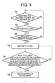
- FIG. 3 is a flow chart of a control method of the present embodiment executed with the ECU.
- a turbocharged diesel engine of the present embodiment is shown in FIG. 1.
- a turbocharged diesel engine 10 comprises an engine body 11, a turbocharger 12, an intake passage 15, an exhaust passage 16, and an EGR unit 26.
- the engine body 11 comprises a combustion chamber 25. Further, the engine body 11 also comprises a fuel injector 18 for injecting fuel into the combustion chamber 25 and an engine revolution speed sensor 22 serving as engine revolution speed detection means for detecting the engine revolution speed.
- the turbocharger 12 comprises a turbine 13 and a compressor 14, and those turbine 13 and compressor 14 are linked together by a rotary shaft.
- the intake passage 15 is connected at the upstream side thereof to the compressor 14 and at the downstream side thereof to the combustion chamber 25. Furthermore, the intake passage 15 comprises an intercooler 17 for cooling the intake air between the compressor 14 and combustion chamber 25.
- the exhaust passage 16 is connected at the upstream side thereof to the combustion chamber 25 and at the downstream side thereof to the turbine 13.
- the EGR unit 26 comprises an EGR passage 19 linking the intake passage 15 and the exhaust passage 16, an EGR valve 20 that can open and close the EGR passage 19, and an EGR cooler 21 for cooling the exhaust gas.
- the EGR passage 19 is connected at one end thereof to the intake passage 15 downstream of the intercooler 17 and at the other end thereof to the exhaust passage 16 upstream of the turbine 13.
- turbocharged diesel engine 10 also comprises an ECU (Engine Control Unit) 24 and an accelerator opening sensor 23 serving as accelerator opening degree detection means for detecting the accelerator opening degree.
- ECU Engine Control Unit
- accelerator opening sensor 23 serving as accelerator opening degree detection means for detecting the accelerator opening degree.
- the ECU 24 is connected to the engine revolution speed sensor 22 and accelerator opening degree sensor 23 and signals are transmitted from those sensors. Furthermore, the ECU 24 is connected to the fuel injector 18 and the EGR valve 20 and drive controls those valves.
- the intake air is compressed by the compressor 14 and reaches the intercooler 17 via the intake passage 15.
- the intake air is cooled in the intercooler 17 and then reaches the combustion chamber 25 through the downstream intake passage 25.
- the intake air is mixed with the fuel injected by the fuel injector 18, combusted and discharged as an exhaust gas.
- the exhaust gas reaches the turbine 13 via the exhaust passage 16.
- the exhaust gas drives the turbine 13 and is then discharged via an aftertreatment unit or the like (not shown in the figure).
- Part of the exhaust gas located in the exhaust passage 16 flows into the EGR passage 19 and reaches the EGR cooler 21.
- the exhaust gas is cooled in the EGR cooler 21 and returned to the intake passage 15.
- the flow of the exhaust gas in this process in shown by a solid line.
- the exhaust gas is mixed with the intake air in the intake passage 15 and the mixture flows into the combustion chamber 25.
- the ECU 24 open-close controls the EGR valve 20 and adjusts the EGR ratio based on the operation state (engine revolution speed, accelerator opening degree, and the like) of the engine body 11.
- the deceleration decision means that decides that the vehicle is decelerating and intake air release means that opens the EGR valve 20, and causes part of the intake air present in the intake passage 15 to flow into the exhaust passage 16 via the EGR passage 19, thereby reducing the intake pressure inside the intake passage 15, when the deceleration decision means decides that the vehicle is decelerating.
- the deceleration decision means is composed of the ECU 24, engine revolution speed sensor 22, and accelerator opening degree sensor 23. A decision is made that the vehicle has decelerated when the engine revolution speed is within the predetermined range and the acceleration opening degree is zero.
- the intake air release means is composed of the ECU 24.
- the deceleration decision means makes a decision that the vehicle is decelerating, this means completely opens the EGR valve 20.
- step 1 the ECU 24 decides as to whether the engine revolution speed is 500 rpm or more and 2000 rpm or less.
- the engine revolution speed is 500 rpm or less, the engine is considered to be in an idling mode and the vehicle is considered to be stopped. Therefore, the decision that the vehicle has decelerated is not made.
- step 2 the ECU 24 decides as to whether the EGR valve 20 has been completely open and then in step 3 decides as to whether the acceleration opening degree is zero.
- the ECU 24 decides that the conditions of each step are satisfied, it moves to the next step, but when the conditions of each step are not satisfied, the processing flow returns to step 1 and the decision process is repeated.
- the ECU 24 completely opens the EGR valve 20 in step 4. In other words, the ECU 24 decides that the vehicle has decelerated when the engine revolution speed is within the predetermined range (500 rpm or more and 2000 rpm or less) and the acceleration opening degree is zero.
- step 5 the ECU 24 makes a decision relating to the following conditions 1 ⁇ to 4 ⁇ : the acceleration opening degree is not zero ... 1 ⁇ ; the engine revolution speed is 500 rpm or less ... 2 ⁇ ; the engine revolution speed is 2000 rpm or more ... 3 ⁇ ; and the EGR valve was open for 3 seconds or more ... 4 ⁇ . If even one of those conditions is satisfied, the processing flow moves to step 6 and usual control of the EGR 20 is conducted based on the engine operation state.
- FIG. 2 shows the relation between the inlet/outlet pressure ratio (P2/P1) and intake flow rate in the compressor 14.
- P 1 is an intake pressure on the inlet side of the compressor 14
- P2 is an intake pressure on the outlet side of the compressor 14.
- the dash-dot line in the figure is a surge line and surging occurs on the left side from the surge line.
- the broken line in the figure illustrates changes at the time of vehicle deceleration in a conventional example in which the EGR valve 20 is fully closed.
- the intake pressure intake pressure P2 on the outlet side of the compressor 14
- the intake flow rate crosses the surge line and decreases.
- the intake flow rate occasionally increases because the intake valve of the engine body 11 opens and the intake pressure inside the intake passage 15 decreases.
- the solid line in the figure illustrates changes at the time of vehicle deceleration in the present embodiment in which the EGR valve 20 is fully open.
- the intake pressure (intake pressure P2 on the outlet side of the compressor 14) inside the intake pressure 15 decreases.
- the intake flow rate increases by comparison with the conventional example and does not cross the surge line and surging does not occur.
- turbocharged diesel engine 10 of the present embodiment surging of the compressor 14 can be prevented by decreasing the intake pressure inside the intake passage 15 when the vehicle is decelerating.
- the EGR unit 26 is used as means for releasing the intake pressure inside the intake passage, it is not necessary to install separately a passage or a valve for intake air release and a simple low-cost structure can be obtained.
- deceleration decision means may decide as to whether the vehicle has decelerated based on changes in the engine revolution speed.
- deceleration decision means may comprise a vehicle speed sensor for detecting the vehicle speed and may decide as to whether the vehicle has decelerated based on changes in the vehicle speed.
- the turbocharged engine of the present embodiment demonstrates an excellent effect of preventing the compressor from surging when the vehicle is decelerating.
Landscapes
- Engineering & Computer Science (AREA)
- Chemical & Material Sciences (AREA)
- Combustion & Propulsion (AREA)
- Mechanical Engineering (AREA)
- General Engineering & Computer Science (AREA)
- Exhaust-Gas Circulating Devices (AREA)
- Output Control And Ontrol Of Special Type Engine (AREA)
- Supercharger (AREA)
- Control Of Positive-Displacement Air Blowers (AREA)
Abstract
Description
Claims (8)
- A turbocharged engine comprising an EGR unit having an EGR passage linking an intake passage and an exhaust passage and an EGR valve provided in said EGR passage, said engine further comprising:deceleration deciding means for deciding as to whether a vehicle decelerates; andintake air release means for opening said EGR valve and releasing part of the intake air present in said intake passage into said exhaust passage through said EGR passage when said deceleration deciding means decides that the vehicle is decelerating.
- The turbocharged engine according to claim 1, comprising:engine revolution speed detection means for detecting the engine revolution speed; andaccelerator opening degree detection means for detecting the accelerator opening degree, characterized in thatsaid deceleration deciding means decides that the vehicle has decelerated when the engine revolution speed detected by said engine revolution speed detection means is within a prescribed range and the accelerator opening degree detected by said accelerator opening degree detection means is zero.
- The turbocharged engine according to claim 2, characterized in that said prescribed range is 500 rpm or higher to 2000 rpm or less.
- The turbocharged engine according to claim 2 or 3, characterized in that said engine revolution speed detection means is an engine revolution speed sensor.
- The turbocharged engine according to any one of claims 2 to 4, characterized in that said accelerator opening degree detection means is an accelerator opening degree sensor.
- The turbocharged engine according to any one of claims 1 to 5, characterized in that said intake air release means closes said EGR valve once a prescribed time elapses after said EGR valve was opened.
- The turbocharged engine according to claim 6, characterized in that said prescribed time is 3 seconds.
- A method for preventing surging in a compressor of a turbocharged engine comprising an EGR unit having an EGR passage linking an intake passage and an exhaust passage and an EGR valve provided in said EGR passage, wherein the intake pressure in said intake passage is reduced by opening said EGR valve and causing part of the intake air present in said intake passage to flow into said exhaust passage via said EGR passage when a decision is made that a vehicle is decelerating.
Applications Claiming Priority (2)
| Application Number | Priority Date | Filing Date | Title |
|---|---|---|---|
| JP2003158299A JP4134816B2 (en) | 2003-06-03 | 2003-06-03 | Turbocharged engine |
| JP2003158299 | 2003-06-03 |
Publications (3)
| Publication Number | Publication Date |
|---|---|
| EP1484497A2 true EP1484497A2 (en) | 2004-12-08 |
| EP1484497A3 EP1484497A3 (en) | 2005-09-14 |
| EP1484497B1 EP1484497B1 (en) | 2008-09-03 |
Family
ID=33157160
Family Applications (1)
| Application Number | Title | Priority Date | Filing Date |
|---|---|---|---|
| EP04012795A Expired - Lifetime EP1484497B1 (en) | 2003-06-03 | 2004-05-28 | Turbocharged engine and method for preventing surging in compressor |
Country Status (5)
| Country | Link |
|---|---|
| US (1) | US7047742B2 (en) |
| EP (1) | EP1484497B1 (en) |
| JP (1) | JP4134816B2 (en) |
| CN (1) | CN1573045B (en) |
| DE (1) | DE602004016251D1 (en) |
Cited By (8)
| Publication number | Priority date | Publication date | Assignee | Title |
|---|---|---|---|---|
| WO2009020418A1 (en) * | 2007-05-16 | 2009-02-12 | Scania Cv Ab (Publ) | A surge control method |
| WO2011124109A1 (en) * | 2010-04-09 | 2011-10-13 | Xie Guohua | Air inlet sectioning device for internal combustion engine |
| FR2964416A1 (en) * | 2010-09-07 | 2012-03-09 | Peugeot Citroen Automobiles Sa | Motor vehicle diesel type four-cylinder engine controlling method, involves opening exhaust gas recirculation and proportioning valves to generate air flow through recirculation valve moving from intake manifold toward exhaust manifold |
| EP1770270A3 (en) * | 2005-10-03 | 2012-10-10 | Deere & Company | EGR system having reverse flow, internal combustion engine and method |
| EP2857661A4 (en) * | 2012-05-30 | 2016-03-02 | Isuzu Motors Ltd | COMBUSTION ENGINE AND CONTROL PROCESS THEREFOR |
| US9388771B2 (en) | 2010-03-01 | 2016-07-12 | Komatsu Ltd. | Intake controller and method of intake controlling for internal combustion engine |
| US10343757B2 (en) | 2010-06-15 | 2019-07-09 | Ge Global Sourcing Llc | Method and system for controlling engine performance |
| CN110735669A (en) * | 2019-10-08 | 2020-01-31 | 中国航发沈阳发动机研究所 | Method and device for judging rotating stall of aviation gas turbine engine |
Families Citing this family (36)
| Publication number | Priority date | Publication date | Assignee | Title |
|---|---|---|---|---|
| WO2006022635A1 (en) * | 2004-07-23 | 2006-03-02 | Honeywell International, Inc. | Use of compressor to turbine bypass for electric boosting system |
| JP4367335B2 (en) * | 2004-12-27 | 2009-11-18 | 日産自動車株式会社 | Engine control device. |
| JP4713147B2 (en) * | 2004-12-27 | 2011-06-29 | 日産自動車株式会社 | Engine control device |
| SE530766C2 (en) * | 2005-03-09 | 2008-09-09 | Komatsu Mfg Co Ltd | Turbocharged engine with exhaust gas recirculation device |
| FI119117B (en) | 2005-06-02 | 2008-07-31 | Waertsilae Finland Oy | Method and apparatus for a turbocharged piston engine |
| JP4595701B2 (en) * | 2005-06-21 | 2010-12-08 | トヨタ自動車株式会社 | Control device for internal combustion engine having supercharger with electric motor |
| US7322194B2 (en) * | 2005-09-28 | 2008-01-29 | Ford Global Technologies Llc | System and method for reducing surge |
| US7357125B2 (en) * | 2005-10-26 | 2008-04-15 | Honeywell International Inc. | Exhaust gas recirculation system |
| JP4240045B2 (en) * | 2006-03-23 | 2009-03-18 | トヨタ自動車株式会社 | Exhaust gas purification system for internal combustion engine |
| JP4635929B2 (en) * | 2006-03-27 | 2011-02-23 | いすゞ自動車株式会社 | Engine combustion control method and combustion control apparatus |
| CN101082318B (en) * | 2006-05-31 | 2011-09-21 | 卡特彼勒公司 | Turbo-charger control system |
| JP4462282B2 (en) * | 2007-03-14 | 2010-05-12 | トヨタ自動車株式会社 | Exhaust control device for internal combustion engine |
| JP4844569B2 (en) * | 2008-01-11 | 2011-12-28 | トヨタ自動車株式会社 | Internal combustion engine supercharging system |
| EP2083154A1 (en) * | 2008-01-23 | 2009-07-29 | Technische Universiteit Eindhoven | Air-inlet system for internal combustion engine, air-conditioning system and combustion engine comprising the air-inlet system |
| US8185285B2 (en) * | 2008-04-08 | 2012-05-22 | GM Global Technology Operations LLC | Transmission hydraulic pressure sensor based altitude measurement |
| US8272215B2 (en) * | 2008-05-28 | 2012-09-25 | Ford Global Technologies, Llc | Transient compressor surge response for a turbocharged engine |
| US8056339B2 (en) * | 2010-01-08 | 2011-11-15 | Ford Global Technologies, Llc | Warming intake air using EGR cooler in dual-throttle boosted engine system |
| JP5787988B2 (en) * | 2010-05-19 | 2015-09-30 | ボーグワーナー インコーポレーテッド | Turbocharger |
| JP5382213B2 (en) * | 2010-05-21 | 2014-01-08 | トヨタ自動車株式会社 | Internal combustion engine and control device for internal combustion engine |
| JP5874161B2 (en) * | 2010-10-28 | 2016-03-02 | いすゞ自動車株式会社 | Turbocharger system |
| US8161746B2 (en) | 2011-03-29 | 2012-04-24 | Ford Global Technologies, Llc | Method and system for providing air to an engine |
| JP5825994B2 (en) * | 2011-11-25 | 2015-12-02 | 日立オートモティブシステムズ株式会社 | Control device for internal combustion engine |
| JP2013167218A (en) * | 2012-02-16 | 2013-08-29 | Toyota Motor Corp | Recirculating device of internal combustion engine |
| US9169809B2 (en) | 2012-08-20 | 2015-10-27 | Ford Global Technologies, Llc | Method for controlling a variable charge air cooler |
| US9194319B2 (en) * | 2013-01-25 | 2015-11-24 | General Electric Company | Methods for intentional turbo surging for enhanced system control and protections |
| US20140316675A1 (en) * | 2013-04-18 | 2014-10-23 | Ford Global Technologies, Llc | Preserving combustion stability during compressor-surge conditions |
| US9074541B2 (en) | 2013-10-25 | 2015-07-07 | Ford Global Technologies, Llc | Method and system for control of an EGR valve during lean operation in a boosted engine system |
| US9145852B2 (en) * | 2014-01-03 | 2015-09-29 | Deere & Company | Power system comprising an EGR system |
| US10094337B2 (en) * | 2015-03-10 | 2018-10-09 | Fca Us Llc | Dual path cooled exhaust gas recirculation for turbocharged gasoline engines |
| CN104832221B (en) * | 2015-03-24 | 2016-04-27 | 清华大学 | Turbosupercharging Surge Prevention System |
| US10190483B2 (en) * | 2016-11-23 | 2019-01-29 | GM Global Technology Operations LLC | Method of controlling a pressure ratio in a flow of compressed combustion air |
| WO2019165429A1 (en) * | 2018-02-26 | 2019-08-29 | Purdue Research Foundation | System and method for avoiding compressor surge during cylinder deactivation of a diesel engine |
| JP2020076391A (en) * | 2018-11-09 | 2020-05-21 | 株式会社豊田自動織機 | Control device of engine, control method of engine, and engine |
| CN111441997B (en) * | 2020-04-19 | 2025-09-05 | 东风商用车有限公司 | A natural gas engine anti-surge system |
| US11649761B1 (en) * | 2021-12-22 | 2023-05-16 | Caterpillar Inc. | Systems for methanol vaporization |
| CN119778084B (en) * | 2024-12-31 | 2026-01-02 | 芜湖埃科泰克动力总成有限公司 | Turbocharger control methods, devices, equipment and readable storage media |
Family Cites Families (13)
| Publication number | Priority date | Publication date | Assignee | Title |
|---|---|---|---|---|
| DE3225867A1 (en) | 1982-07-10 | 1984-01-12 | Audi Nsu Auto Union Ag, 7107 Neckarsulm | Internal combustion engine with an exhaust turbocharger |
| DE3244928C2 (en) * | 1982-12-04 | 1985-07-18 | M.A.N. Maschinenfabrik Augsburg-Nürnberg AG, 8900 Augsburg | Combined charge air circulation and exhaust gas relief valve on a supercharged internal combustion engine |
| JPS59138749A (en) | 1983-01-28 | 1984-08-09 | Hino Motors Ltd | Suction bypass adjuster for engine |
| JPS6045730A (en) | 1983-08-24 | 1985-03-12 | Suzuki Motor Co Ltd | Turbo-operation indicator |
| JP3376633B2 (en) | 1993-03-31 | 2003-02-10 | いすゞ自動車株式会社 | Exhaust gas recirculation control device for turbocharged engine with rotating electric machine |
| US5724813A (en) | 1996-01-26 | 1998-03-10 | Caterpillar Inc. | Compressor by-pass and valving for a turbocharger |
| DE19913792A1 (en) * | 1999-03-26 | 2000-10-05 | Daimler Chrysler Ag | Charged internal combustion engine operating process, involving overflow line being forced open at set pressure difference to return exhaust gas to charge air line |
| JP4323680B2 (en) | 1999-09-30 | 2009-09-02 | 株式会社小松製作所 | Exhaust gas recirculation control device for internal combustion engine |
| DE19963358A1 (en) * | 1999-12-28 | 2001-07-12 | Bosch Gmbh Robert | Method and device for controlling an internal combustion engine with an air system |
| EP1138928B1 (en) | 2000-03-27 | 2013-04-24 | Mack Trucks, Inc. | Turbocharged engine with exhaust gas recirculation |
| JP3873742B2 (en) * | 2001-12-28 | 2007-01-24 | いすゞ自動車株式会社 | Control device for variable capacity turbocharger |
| US6675579B1 (en) * | 2003-02-06 | 2004-01-13 | Ford Global Technologies, Llc | HCCI engine intake/exhaust systems for fast inlet temperature and pressure control with intake pressure boosting |
| US6868840B2 (en) * | 2003-06-05 | 2005-03-22 | Detroit Diesel Corporation | Charged air intake system for an internal combustion engine |
-
2003
- 2003-06-03 JP JP2003158299A patent/JP4134816B2/en not_active Expired - Fee Related
-
2004
- 2004-04-16 CN CN200410034850XA patent/CN1573045B/en not_active Expired - Fee Related
- 2004-05-26 US US10/854,530 patent/US7047742B2/en not_active Expired - Fee Related
- 2004-05-28 EP EP04012795A patent/EP1484497B1/en not_active Expired - Lifetime
- 2004-05-28 DE DE602004016251T patent/DE602004016251D1/en not_active Expired - Lifetime
Cited By (9)
| Publication number | Priority date | Publication date | Assignee | Title |
|---|---|---|---|---|
| EP1770270A3 (en) * | 2005-10-03 | 2012-10-10 | Deere & Company | EGR system having reverse flow, internal combustion engine and method |
| WO2009020418A1 (en) * | 2007-05-16 | 2009-02-12 | Scania Cv Ab (Publ) | A surge control method |
| US9388771B2 (en) | 2010-03-01 | 2016-07-12 | Komatsu Ltd. | Intake controller and method of intake controlling for internal combustion engine |
| DE112011100755B4 (en) | 2010-03-01 | 2018-09-27 | Komatsu Ltd. | An intake control device and method of an intake control for an internal combustion engine |
| WO2011124109A1 (en) * | 2010-04-09 | 2011-10-13 | Xie Guohua | Air inlet sectioning device for internal combustion engine |
| US10343757B2 (en) | 2010-06-15 | 2019-07-09 | Ge Global Sourcing Llc | Method and system for controlling engine performance |
| FR2964416A1 (en) * | 2010-09-07 | 2012-03-09 | Peugeot Citroen Automobiles Sa | Motor vehicle diesel type four-cylinder engine controlling method, involves opening exhaust gas recirculation and proportioning valves to generate air flow through recirculation valve moving from intake manifold toward exhaust manifold |
| EP2857661A4 (en) * | 2012-05-30 | 2016-03-02 | Isuzu Motors Ltd | COMBUSTION ENGINE AND CONTROL PROCESS THEREFOR |
| CN110735669A (en) * | 2019-10-08 | 2020-01-31 | 中国航发沈阳发动机研究所 | Method and device for judging rotating stall of aviation gas turbine engine |
Also Published As
| Publication number | Publication date |
|---|---|
| CN1573045A (en) | 2005-02-02 |
| JP2004360525A (en) | 2004-12-24 |
| EP1484497B1 (en) | 2008-09-03 |
| US20040244375A1 (en) | 2004-12-09 |
| DE602004016251D1 (en) | 2008-10-16 |
| EP1484497A3 (en) | 2005-09-14 |
| JP4134816B2 (en) | 2008-08-20 |
| CN1573045B (en) | 2010-07-21 |
| US7047742B2 (en) | 2006-05-23 |
Similar Documents
| Publication | Publication Date | Title |
|---|---|---|
| US7047742B2 (en) | Turbocharged engine and method for preventing surging in compressor | |
| US6886544B1 (en) | Exhaust gas venturi injector for an exhaust gas recirculation system | |
| US6338245B1 (en) | Internal combustion engine | |
| US8006494B2 (en) | Exhaust gas recirculation apparatus for internal combustion engine and method of controlling exhaust gas recirculation apparatus | |
| US6945240B2 (en) | Device and method for exhaust gas circulation of internal combustion engine | |
| US6883324B2 (en) | Control apparatus and control method for internal combustion engine | |
| US7610757B2 (en) | Intake controller of internal combustion engine | |
| JP5187123B2 (en) | Control device for internal combustion engine | |
| JP2010265854A (en) | Internal combustion engine with turbocharger and control method thereof | |
| US20060124116A1 (en) | Clean gas injector | |
| JP4492406B2 (en) | Diesel engine intake / exhaust system | |
| EP2211044A1 (en) | EGR controller and EGR control method for internal combustion engine | |
| US20200200100A1 (en) | Throttle Valve Controller Device for Internal Combustion Engine | |
| WO2007066833A1 (en) | Exhaust gas purification system for internal combustion engine | |
| KR102518588B1 (en) | Engine system for exhausting water and method using the same | |
| JP2005188359A (en) | Internal combustion engine with a supercharger | |
| JP6073644B2 (en) | Control device for exhaust pressure adjustment valve | |
| JP2018184870A (en) | Engine control device | |
| JP2007016612A (en) | Exhaust pressure control device for internal combustion engine | |
| KR101887954B1 (en) | Surge Control Apparatus and Control Method thereof for Turbo-Charger | |
| JP4000923B2 (en) | Inlet throttle valve control device for turbocharged diesel engine for vehicle | |
| JP2025131006A (en) | vehicle | |
| JP2008075545A (en) | Engine supercharger | |
| JP2013189907A (en) | Control device for internal combustion engine | |
| JPH05340310A (en) | Egr control method in diesel engine |
Legal Events
| Date | Code | Title | Description |
|---|---|---|---|
| PUAI | Public reference made under article 153(3) epc to a published international application that has entered the european phase |
Free format text: ORIGINAL CODE: 0009012 |
|
| AK | Designated contracting states |
Kind code of ref document: A2 Designated state(s): AT BE BG CH CY CZ DE DK EE ES FI FR GB GR HU IE IT LI LU MC NL PL PT RO SE SI SK TR |
|
| AX | Request for extension of the european patent |
Extension state: AL HR LT LV MK |
|
| PUAL | Search report despatched |
Free format text: ORIGINAL CODE: 0009013 |
|
| AK | Designated contracting states |
Kind code of ref document: A3 Designated state(s): AT BE BG CH CY CZ DE DK EE ES FI FR GB GR HU IE IT LI LU MC NL PL PT RO SE SI SK TR |
|
| AX | Request for extension of the european patent |
Extension state: AL HR LT LV MK |
|
| RIC1 | Information provided on ipc code assigned before grant |
Ipc: 7F 02M 25/07 A Ipc: 7F 02D 23/00 B Ipc: 7F 02B 37/16 B Ipc: 7F 02D 41/00 B |
|
| 17P | Request for examination filed |
Effective date: 20051014 |
|
| AKX | Designation fees paid |
Designated state(s): DE FR GB IT |
|
| 17Q | First examination report despatched |
Effective date: 20051125 |
|
| 17Q | First examination report despatched |
Effective date: 20051125 |
|
| GRAP | Despatch of communication of intention to grant a patent |
Free format text: ORIGINAL CODE: EPIDOSNIGR1 |
|
| GRAS | Grant fee paid |
Free format text: ORIGINAL CODE: EPIDOSNIGR3 |
|
| GRAA | (expected) grant |
Free format text: ORIGINAL CODE: 0009210 |
|
| AK | Designated contracting states |
Kind code of ref document: B1 Designated state(s): DE FR GB IT |
|
| REG | Reference to a national code |
Ref country code: GB Ref legal event code: FG4D |
|
| REF | Corresponds to: |
Ref document number: 602004016251 Country of ref document: DE Date of ref document: 20081016 Kind code of ref document: P |
|
| PLBE | No opposition filed within time limit |
Free format text: ORIGINAL CODE: 0009261 |
|
| STAA | Information on the status of an ep patent application or granted ep patent |
Free format text: STATUS: NO OPPOSITION FILED WITHIN TIME LIMIT |
|
| 26N | No opposition filed |
Effective date: 20090604 |
|
| PGFP | Annual fee paid to national office [announced via postgrant information from national office to epo] |
Ref country code: IT Payment date: 20100520 Year of fee payment: 7 |
|
| PG25 | Lapsed in a contracting state [announced via postgrant information from national office to epo] |
Ref country code: IT Free format text: LAPSE BECAUSE OF NON-PAYMENT OF DUE FEES Effective date: 20110528 |
|
| REG | Reference to a national code |
Ref country code: FR Ref legal event code: PLFP Year of fee payment: 13 |
|
| REG | Reference to a national code |
Ref country code: FR Ref legal event code: PLFP Year of fee payment: 14 |
|
| PGFP | Annual fee paid to national office [announced via postgrant information from national office to epo] |
Ref country code: GB Payment date: 20170524 Year of fee payment: 14 Ref country code: FR Payment date: 20170413 Year of fee payment: 14 Ref country code: DE Payment date: 20170523 Year of fee payment: 14 |
|
| REG | Reference to a national code |
Ref country code: DE Ref legal event code: R119 Ref document number: 602004016251 Country of ref document: DE |
|
| GBPC | Gb: european patent ceased through non-payment of renewal fee |
Effective date: 20180528 |
|
| PG25 | Lapsed in a contracting state [announced via postgrant information from national office to epo] |
Ref country code: GB Free format text: LAPSE BECAUSE OF NON-PAYMENT OF DUE FEES Effective date: 20180528 Ref country code: DE Free format text: LAPSE BECAUSE OF NON-PAYMENT OF DUE FEES Effective date: 20181201 Ref country code: FR Free format text: LAPSE BECAUSE OF NON-PAYMENT OF DUE FEES Effective date: 20180531 |