EP1484477A1 - Handling the rotor of a rotary machine. - Google Patents
Handling the rotor of a rotary machine. Download PDFInfo
- Publication number
- EP1484477A1 EP1484477A1 EP04102497A EP04102497A EP1484477A1 EP 1484477 A1 EP1484477 A1 EP 1484477A1 EP 04102497 A EP04102497 A EP 04102497A EP 04102497 A EP04102497 A EP 04102497A EP 1484477 A1 EP1484477 A1 EP 1484477A1
- Authority
- EP
- European Patent Office
- Prior art keywords
- rotor
- machine
- plate
- support block
- lifting device
- Prior art date
- Legal status (The legal status is an assumption and is not a legal conclusion. Google has not performed a legal analysis and makes no representation as to the accuracy of the status listed.)
- Granted
Links
- 238000000034 method Methods 0.000 claims abstract description 9
- 238000004873 anchoring Methods 0.000 claims description 2
- 230000006378 damage Effects 0.000 description 3
- 230000008439 repair process Effects 0.000 description 3
- 241001124569 Lycaenidae Species 0.000 description 2
- 208000027418 Wounds and injury Diseases 0.000 description 1
- 230000005484 gravity Effects 0.000 description 1
- 208000014674 injury Diseases 0.000 description 1
- 238000003780 insertion Methods 0.000 description 1
- 230000037431 insertion Effects 0.000 description 1
- 230000000284 resting effect Effects 0.000 description 1
- 238000000926 separation method Methods 0.000 description 1
Images


Classifications
-
- A—HUMAN NECESSITIES
- A01—AGRICULTURE; FORESTRY; ANIMAL HUSBANDRY; HUNTING; TRAPPING; FISHING
- A01D—HARVESTING; MOWING
- A01D41/00—Combines, i.e. harvesters or mowers combined with threshing devices
-
- A—HUMAN NECESSITIES
- A01—AGRICULTURE; FORESTRY; ANIMAL HUSBANDRY; HUNTING; TRAPPING; FISHING
- A01D—HARVESTING; MOWING
- A01D75/00—Accessories for harvesters or mowers
-
- Y—GENERAL TAGGING OF NEW TECHNOLOGICAL DEVELOPMENTS; GENERAL TAGGING OF CROSS-SECTIONAL TECHNOLOGIES SPANNING OVER SEVERAL SECTIONS OF THE IPC; TECHNICAL SUBJECTS COVERED BY FORMER USPC CROSS-REFERENCE ART COLLECTIONS [XRACs] AND DIGESTS
- Y10—TECHNICAL SUBJECTS COVERED BY FORMER USPC
- Y10T—TECHNICAL SUBJECTS COVERED BY FORMER US CLASSIFICATION
- Y10T29/00—Metal working
- Y10T29/49—Method of mechanical manufacture
- Y10T29/49448—Agricultural device making
-
- Y—GENERAL TAGGING OF NEW TECHNOLOGICAL DEVELOPMENTS; GENERAL TAGGING OF CROSS-SECTIONAL TECHNOLOGIES SPANNING OVER SEVERAL SECTIONS OF THE IPC; TECHNICAL SUBJECTS COVERED BY FORMER USPC CROSS-REFERENCE ART COLLECTIONS [XRACs] AND DIGESTS
- Y10—TECHNICAL SUBJECTS COVERED BY FORMER USPC
- Y10T—TECHNICAL SUBJECTS COVERED BY FORMER US CLASSIFICATION
- Y10T29/00—Metal working
- Y10T29/49—Method of mechanical manufacture
- Y10T29/49815—Disassembling
-
- Y—GENERAL TAGGING OF NEW TECHNOLOGICAL DEVELOPMENTS; GENERAL TAGGING OF CROSS-SECTIONAL TECHNOLOGIES SPANNING OVER SEVERAL SECTIONS OF THE IPC; TECHNICAL SUBJECTS COVERED BY FORMER USPC CROSS-REFERENCE ART COLLECTIONS [XRACs] AND DIGESTS
- Y10—TECHNICAL SUBJECTS COVERED BY FORMER USPC
- Y10T—TECHNICAL SUBJECTS COVERED BY FORMER US CLASSIFICATION
- Y10T29/00—Metal working
- Y10T29/49—Method of mechanical manufacture
- Y10T29/49815—Disassembling
- Y10T29/49822—Disassembling by applying force
Definitions
- the present invention relates to method and apparatus for handling the rotor of a rotary machine, in particular a rotary combine harvester.
- Rotary combine harvesters have either one rotor or two counter-rotating rotors that extend lengthways parallel to one another. They are inclined to the horizontal, their front ends being mounted lower than their rear ends.
- the manner in which the rotors function is itself well known and it will not be described herein, more particularly as it is not relevant to the invention. Within the present context, it suffices to know that the rotors are large and heavy and that from time to time they need to be removed for servicing and repair.
- Removal of the rotor(s) of a combine harvester (and its subsequent replacement) is a labour intensive task requiring several men on account of the size and weight of the rotor. Its size also makes it difficult to support and maneuver the rotor while repairs are being carried out on it.
- a particular problem presented by the rotor of a rotary combine harvester is that its axis is inclined and there is a risk of damage to the machine and personal injury, if once it has been freed, the rotor slides under gravity out of the machine.
- the object of the present invention is therefore to simplify the tasks of removal, repair and replacement of the rotor of a large rotary machine.
- a method of removing a rotor of a rotary machine such as a rotary combine harvester, which comprises the steps of:
- the number of people needed to remove and later replace a rotor is reduced because the weight is supported not by men but by the lifting device.
- the lifting device is preferably a forklift truck, this being a lifting device that farmers will normally have at their disposal.
- an extension arm to the support block to support the weight of the rotor at a distance from the plate as the rotor is extracted from the machine in order to reduce the moment of the rotor about the plate.
- the support block and its extension arm provide a suitable frame on which the rotor can rest while it is being serviced or repaired.
- the same support block can of course also be used to replace the rotor, this time the truck being driven forward at the same time as its fork is raised.
- an apparatus for removing a rotor of a rotary machine comprising a support block having a base designed to be anchored to the lifting platform of a movable lifting device, a plate mounted on the support block and anchoring points on the plate for enable the plate to be firmly secured to one end of the rotor.
- the base comprises two hollow girders dimensioned and positioned to receive the prongs of the lifting platform of a movable lifting device.
- the apparatus and method of the invention can be used with a wide variety of rotary machines, such as turbines, they have particular application to rotary combine harvesters, where a rotor is inclined to the horizontal.
- the plate is preferably rotatable relative to the support block. This can conveniently be achieved by mounting the plate on a shaft that is journalled on the support block by means of at least two pillar blocks.
- an extension arm for the support block is further provided for supporting the weight of the rotor at a point along its length spaced from the plate.
- a support block 10 for withdrawing a rotor from a combine harvester comprises a pair of hollow girders 12 which are dimensioned and spaced apart to receive the prongs 14 of a fork lift truck 16.
- a tunnel 18 of tapering height is welded to the top surfaces of the two girders 12 and its top surface carries two pillow blocks 20 within which there is journalled a shaft 22.
- the front end of the shaft 22 is provided with a plate 24 having holes that enable it to be bolted to the front face of a rotor of a combine harvester.
- the support block also has an extension arm 30 that can be inserted into a hole 38 formed on the underside of the support block 10.
- the extension arm 30 has a horizontal limb 32, a telescopic vertical limb 34 and a brace 36.
- Various locking pins are used to prevent the support block from moving on the prongs 14 of the fork lift truck 16, to lock the horizontal limb 32 of the extension arm 30 relative to the support block 10 and to prevent collapse of the telescopic vertical limb 34.
- a rotary combine harvester may have one or two rotors but the one shown in Figures 5 to 8 has two counter rotating rotors 40,42. These rotors are inclined relative to the horizontal when the harvester is standing on level ground. The front ends of the rotors 40, 42 are journalled on a cross member 44, which needs to be removed before either of the rotors can be withdrawn. However, there is a risk of the rotors sliding out of the combine harvester once the cross member is removed and the first step taken is therefore to secure the two rotors in position. The manner in which this is done will depend on the harvester but as an example it is possible to insert a bar through holes in a grill plate that underlies the rotors.
- the plate 24 of the support block 10 is now offered up to the exposed end of the rotor to be removed and it is bolted on to the front end of the rotor.
- the positioning of the plate 24 into alignment with the end of the rotor is carried out by raising or lowering the support block using the fork lift truck and driving the truck forwards or backwards, as necessary. If necessary, the shaft 22 can be rotated by hand to ensure that holes in the plate 24 line up with holes in the end of the rotor.
- the extension arm 30 is added to the support block 10 to take the weight of the rotor at a point along its length.
- the support block 10 can now be rested on the ground and the prongs of the forklift truck can be withdrawn. Any necessary work can be carried out on the rotor while it is supported in this manner and it can be rotated as desired to work on it its different parts.
- Replacement of the rotor is carried out in essentially the reverse order.
- the upper end of the rotor is first introduced into the harvester, after its partial insertion, the extension arm is removed, next it is driven to its end position and locked in position.
- the rotor can be rotated about its own axis for correct angular alignment with the other rotor or other machine components.
- the cross member 44 can be replaced and the rotor is then freed for normal operation by removal of any locking bar used to hold it in place after its unbolting from the support block 10.
Landscapes
- Life Sciences & Earth Sciences (AREA)
- Environmental Sciences (AREA)
- Combines (AREA)
- Threshing Machine Elements (AREA)
- Vaporization, Distillation, Condensation, Sublimation, And Cold Traps (AREA)
- Holding Or Fastening Of Disk On Rotational Shaft (AREA)
- Harvesting Machines For Root Crops (AREA)
- Harvester Elements (AREA)
Abstract
Description
- The present invention relates to method and apparatus for handling the rotor of a rotary machine, in particular a rotary combine harvester.
- Rotary combine harvesters have either one rotor or two counter-rotating rotors that extend lengthways parallel to one another. They are inclined to the horizontal, their front ends being mounted lower than their rear ends. The manner in which the rotors function is itself well known and it will not be described herein, more particularly as it is not relevant to the invention. Within the present context, it suffices to know that the rotors are large and heavy and that from time to time they need to be removed for servicing and repair.
- Removal of the rotor(s) of a combine harvester (and its subsequent replacement) is a labour intensive task requiring several men on account of the size and weight of the rotor. Its size also makes it difficult to support and maneuver the rotor while repairs are being carried out on it. A particular problem presented by the rotor of a rotary combine harvester is that its axis is inclined and there is a risk of damage to the machine and personal injury, if once it has been freed, the rotor slides under gravity out of the machine.
- The object of the present invention is therefore to simplify the tasks of removal, repair and replacement of the rotor of a large rotary machine.
- According to a first aspect of the invention, there is provided a method of removing a rotor of a rotary machine, such as a rotary combine harvester, which comprises the steps of:
- exposing one end of the rotor while ensuring that the rotor remains safely anchored within the machine,
- securing to the exposed end of the rotor a plate that is mounted on a support block carried on the lifting platform of a movable lifting device,
- disconnecting the rotor from all remaining components of the machine to permit the rotor to be slid out of the machine, and
- moving the lifting device away from the machine while simultaneously controlling the height of its lifting platform to cause the end of the rotor to move along a path parallel to the axis of the rotor and thereby extract the rotor from the machine while supporting the weight of the portion of the rotor projecting from the machine.
-
- In the invention, the number of people needed to remove and later replace a rotor is reduced because the weight is supported not by men but by the lifting device. The lifting device is preferably a forklift truck, this being a lifting device that farmers will normally have at their disposal.
- As the rear end of the rotor comes away from the machine, unless the weight of the rotor is supported elsewhere, excessive torque would act on the plate and the means used to anchor the plate to the rotor.
- It is therefore preferred to attach an extension arm to the support block to support the weight of the rotor at a distance from the plate as the rotor is extracted from the machine in order to reduce the moment of the rotor about the plate.
- The support block and its extension arm provide a suitable frame on which the rotor can rest while it is being serviced or repaired. The same support block can of course also be used to replace the rotor, this time the truck being driven forward at the same time as its fork is raised.
- During the replacement of the rotor, it is important to be able to rotate it to time the phase of its rotation correctly in relation to other components (such as the other rotor, if twin rotors are provided). It is therefore preferred to mount the plate rotatably on the support block and to rotate the rotor about its own axis when in the machine.
- According to a second aspect of the invention, there is provided an apparatus for removing a rotor of a rotary machine, such as a rotary combine harvester, comprising a support block having a base designed to be anchored to the lifting platform of a movable lifting device, a plate mounted on the support block and anchoring points on the plate for enable the plate to be firmly secured to one end of the rotor.
- Preferably, the base comprises two hollow girders dimensioned and positioned to receive the prongs of the lifting platform of a movable lifting device.
- Though the apparatus and method of the invention can be used with a wide variety of rotary machines, such as turbines, they have particular application to rotary combine harvesters, where a rotor is inclined to the horizontal. In such an application, it is advantageous for the plane of the plate to be inclined to the plane of the two girders so that the normal to the plate, which extends parallel to the axis of the rotor, is inclined to the horizontal when the support block is carried by a horizontal lifting fork.
- To permit angular positioning, the plate is preferably rotatable relative to the support block. This can conveniently be achieved by mounting the plate on a shaft that is journalled on the support block by means of at least two pillar blocks.
- In the preferred embodiment of the invention, an extension arm for the support block is further provided for supporting the weight of the rotor at a point along its length spaced from the plate.
- The invention will now be described further, by way of example, with reference to the accompanying drawings, in which:
- Figure 1 is a schematic side view of a support block and an extension arm for use in extracting the rotor of a rotary combine harvester,
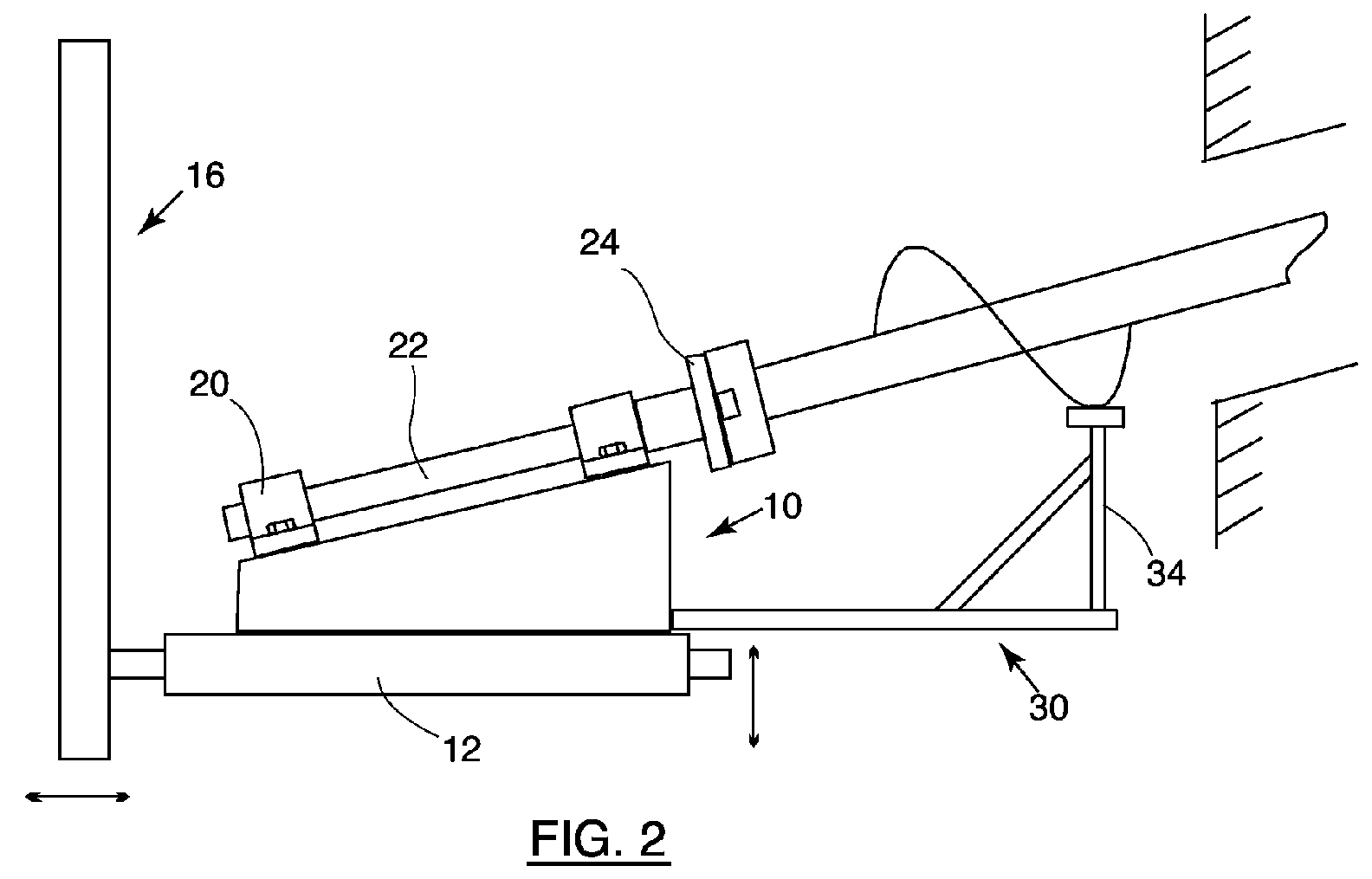
- Figure 2 is a side view of a support block and extension arm when in use,
- Figure 3 is a perspective view of the support block of Figures 1 and 2,
- Figure 4 is a side view of an extension arm similar to that shown in Figures 1 and 2,
- Figure 5 shows the front end of the rotors of a combine harvester before removal of a cross member, on which their front ends are supported,
- Figure 6 shown the front end of the rotors of the combine harvester in Figure 5 after removal of the cross member and connection of the support block of Figure 3 to the exposed end of one of the two counter-rotating rotors,
- Figure 7 is a side view after partial withdrawal of the rotor, and
- Figure 8 shows a detail of the rotor supported along its length on the extension arm of Figure 4 to facilitate its full withdrawal from the combine harvester.
-
- Referring to Figures 1 and 3, a
support block 10 for withdrawing a rotor from a combine harvester comprises a pair ofhollow girders 12 which are dimensioned and spaced apart to receive theprongs 14 of afork lift truck 16. Atunnel 18 of tapering height is welded to the top surfaces of the twogirders 12 and its top surface carries twopillow blocks 20 within which there is journalled ashaft 22. The front end of theshaft 22 is provided with aplate 24 having holes that enable it to be bolted to the front face of a rotor of a combine harvester. - As shown in Figures 1 and 4, the support block also has an
extension arm 30 that can be inserted into ahole 38 formed on the underside of thesupport block 10. Theextension arm 30 has ahorizontal limb 32, a telescopicvertical limb 34 and abrace 36. Various locking pins are used to prevent the support block from moving on theprongs 14 of thefork lift truck 16, to lock thehorizontal limb 32 of theextension arm 30 relative to thesupport block 10 and to prevent collapse of the telescopicvertical limb 34. - A rotary combine harvester may have one or two rotors but the one shown in Figures 5 to 8 has two
counter rotating rotors rotors cross member 44, which needs to be removed before either of the rotors can be withdrawn. However, there is a risk of the rotors sliding out of the combine harvester once the cross member is removed and the first step taken is therefore to secure the two rotors in position. The manner in which this is done will depend on the harvester but as an example it is possible to insert a bar through holes in a grill plate that underlies the rotors. - Having secured the
rotors cross member 44, the latter member is removed to expose the front ends of both rotors as shown in Figure 6. - The
plate 24 of thesupport block 10 is now offered up to the exposed end of the rotor to be removed and it is bolted on to the front end of the rotor. The positioning of theplate 24 into alignment with the end of the rotor is carried out by raising or lowering the support block using the fork lift truck and driving the truck forwards or backwards, as necessary. If necessary, theshaft 22 can be rotated by hand to ensure that holes in theplate 24 line up with holes in the end of the rotor. - After the
plate 24 has been bolted to the front end of the rotor, it is safe to remove whatever obstacle remains to the sliding of the rotor out of the combine harvester. Thus if a bar has been jammed between part of the rotor and the machine, that bar may now safely be removed as the weight of the rotor is taken up by the fork lift truck and thesupport block 10. - To slide the rotor out of the harvester, as shown in Figure 7, the driver reverses the fork lift truck and lowers its fork at the same time so that the
plate 24 moves parallel to the axis of the rotor. While the upper end of the rotor remains inside the harvester, it is safely supported at two points. However it is not safe to pull the rotor entirely out of the harvester when only supported by theplate 24, because the torque applied by the weight of the rotor could damage theshaft 22 or the rotor itself. - For this reason, after the rotor has been partly withdrawn from the machine, the
extension arm 30 is added to thesupport block 10 to take the weight of the rotor at a point along its length. - After the
horizontal limb 32 has been slotted into itshole 38 in the support block, its telescopicvertical limb 34 is raised until it contacts the rotor and then locked in position as shown in Figure 8. The reversing of the truck and simultaneous lowering of the fork can now be continued until the entire rotor lies outside the harvester. - The
support block 10 can now be rested on the ground and the prongs of the forklift truck can be withdrawn. Any necessary work can be carried out on the rotor while it is supported in this manner and it can be rotated as desired to work on it its different parts. - Replacement of the rotor is carried out in essentially the reverse order. The upper end of the rotor is first introduced into the harvester, after its partial insertion, the extension arm is removed, next it is driven to its end position and locked in position. During these steps, the rotor can be rotated about its own axis for correct angular alignment with the other rotor or other machine components. After separation of the
plate 24 from the exposed end of the rotor, thecross member 44 can be replaced and the rotor is then freed for normal operation by removal of any locking bar used to hold it in place after its unbolting from thesupport block 10.
Claims (11)
- A method of removing a rotor (40,42) of a rotary machine, such as a rotary combine harvester, characterized in that it comprises the steps of:exposing one end of the rotor (40,42) while ensuring that the rotor (40,42) remains safely anchored within the machine,securing to the exposed end of the rotor (40,42) a plate (24) that is mounted on a support block (10) carried on the lifting platform (14) of a movable lifting device (16) ,disconnecting the rotor (40,42) from all remaining components of the machine to permit the rotor (40,42) to be slid out of the machine, andmoving the lifting device (16) away from the machine while simultaneously controlling the height of its lifting platform (14) to cause the end of the rotor (40,42) to move along a path parallel to the axis of the rotor (40,42) and thereby extract the rotor (40,42) from the machine while supporting the weight of the portion of the rotor (40,42) projecting from the machine.
- A method as claimed in claim 1, characterized in that a forklift truck (16) is used as the movable lifting device.
- A method as claimed in claim 1 or 2, characterized in that it comprises attaching an extension arm (30) to the support block (10) to support the weight of the rotor (40,42) at a distance from the plate (24) as the rotor (40,42) is extracted from the machine in order to reduce the moment of the rotor (40,42) about the plate (24).
- A method as claimed in claim 1, 2 or 3, characterized in that it comprises the additional step of mounting the plate (24) on the support block (10) in a manner to permit the plate (24) to rotate and rotating the rotor (40,42) about its own axis as it is retracted from the machine.
- Apparatus for removing a rotor (40,42) of a rotary machine, such as a rotary combine harvester, characterized in that it comprises a support block (10) having a base designed to be anchored to the lifting platform (14) of a movable lifting device (16), a plate (24) mounted on the support block (10) and anchoring points on the plate (24) for enabling the plate (24) to be firmly secured to one end of the rotor (40,42).
- Apparatus as claimed in claim 5, characterized in that the base comprises two hollow girders (12) dimensioned and positioned to receive the prongs (14) of the lifting fork of a movable lifting device (16).
- Apparatus as claimed in claim 6, characterized in that the plane of the plate (24) is inclined to the plane of the two girders (12) so that the normal to the plate (24), which extends parallel to the axis of the rotor (40,42), is inclined to the horizontal when the support block (10) is carried by a horizontal lifting platform (14).
- Apparatus as claimed in claim 5, 6 or 7, characterized in that the plate (24) is rotatable relative to the support block (10).
- Apparatus as claimed in claim 8, characterized in that the plate (24) is mounted on a shaft (22) that is journalled on the support block (10) by means of at least two pillow blocks (20).
- Apparatus as claimed in any of claims 5 to 9, characterized in that it further comprises an extension arm (30) for supporting the weight of the rotor (40,42) at a point along its length spaced from the plate (24) and means for securing the extension (30) to the support block (10).
- Apparatus as claimed in any of claims 5 to 10, characterized in that a forklift truck (16) is used as the movable lifting device.
Applications Claiming Priority (2)
| Application Number | Priority Date | Filing Date | Title |
|---|---|---|---|
| GB3131778 | 2003-06-07 | ||
| GBGB0313177.8A GB0313177D0 (en) | 2003-06-07 | 2003-06-07 | Handling the rotor of a rotary machine |
Publications (2)
| Publication Number | Publication Date |
|---|---|
| EP1484477A1 true EP1484477A1 (en) | 2004-12-08 |
| EP1484477B1 EP1484477B1 (en) | 2006-11-22 |
Family
ID=27589670
Family Applications (1)
| Application Number | Title | Priority Date | Filing Date |
|---|---|---|---|
| EP04102497A Expired - Lifetime EP1484477B1 (en) | 2003-06-07 | 2004-06-03 | Handling the rotor of a rotary machine. |
Country Status (6)
| Country | Link |
|---|---|
| US (2) | US7174616B2 (en) |
| EP (1) | EP1484477B1 (en) |
| AT (1) | ATE346222T1 (en) |
| DE (1) | DE602004003287T2 (en) |
| DK (1) | DK1484477T3 (en) |
| GB (1) | GB0313177D0 (en) |
Cited By (2)
| Publication number | Priority date | Publication date | Assignee | Title |
|---|---|---|---|---|
| CN103481049A (en) * | 2013-10-10 | 2014-01-01 | 鞍钢集团矿业公司 | Ball mill hollow shaft screw shell installing and detaching device |
| CN106975941A (en) * | 2017-03-29 | 2017-07-25 | 长治清华机械厂 | Arc support type component levelling device |
Families Citing this family (1)
| Publication number | Priority date | Publication date | Assignee | Title |
|---|---|---|---|---|
| CN102950446B (en) * | 2011-08-23 | 2014-10-29 | 哈尔滨建成集团有限公司 | Interfacing device for rotary part type components |
Citations (5)
| Publication number | Priority date | Publication date | Assignee | Title |
|---|---|---|---|---|
| US1045146A (en) * | 1912-11-26 | Pinionv-pullin g mechanism | ||
| US2994443A (en) * | 1958-09-15 | 1961-08-01 | Julian E Gordon | Equipment for removing engine turbine rotors while installed in aircraft |
| US3150820A (en) * | 1962-07-20 | 1964-09-29 | Worthington Corp | Turbine compressor unit |
| US3937443A (en) * | 1975-07-11 | 1976-02-10 | Caterpillar Tractor Co. | Crankcase guard jack utilizing double parallelogram |
| GB2177160A (en) * | 1985-07-04 | 1987-01-14 | Prime Mover Maintenance Limite | Servicing gas turbines |
Family Cites Families (6)
| Publication number | Priority date | Publication date | Assignee | Title |
|---|---|---|---|---|
| US1923126A (en) * | 1932-06-16 | 1933-08-22 | Allis Chalmers Mfg Co | Rotary macuine-peime mover power unit and method of assembling and dismantling the same |
| US4177701A (en) * | 1978-09-05 | 1979-12-11 | Dieter Christoph | Steady rest for use in apparatus for supporting and precision-turning of large rotary devices |
| US5499948A (en) * | 1994-09-01 | 1996-03-19 | Deere & Company | Modular threshing assembly for a combine |
| US6171730B1 (en) * | 1997-11-07 | 2001-01-09 | Canon Kabushiki Kaisha | Exposure method and exposure apparatus |
| US6200083B1 (en) * | 1999-04-08 | 2001-03-13 | Richard Hein | Articulated bucket adapted for a fork-lift truck |
| GB2385505A (en) | 2002-02-22 | 2003-08-27 | Ford New Holland Nv | Tool and method for removal and installation of threshing concaves |
-
2003
- 2003-06-07 GB GBGB0313177.8A patent/GB0313177D0/en not_active Ceased
-
2004
- 2004-05-27 US US10/855,663 patent/US7174616B2/en not_active Expired - Lifetime
- 2004-06-03 DK DK04102497T patent/DK1484477T3/en active
- 2004-06-03 DE DE602004003287T patent/DE602004003287T2/en not_active Expired - Lifetime
- 2004-06-03 EP EP04102497A patent/EP1484477B1/en not_active Expired - Lifetime
- 2004-06-03 AT AT04102497T patent/ATE346222T1/en not_active IP Right Cessation
-
2006
- 2006-12-06 US US11/567,519 patent/US20070107988A1/en not_active Abandoned
Patent Citations (5)
| Publication number | Priority date | Publication date | Assignee | Title |
|---|---|---|---|---|
| US1045146A (en) * | 1912-11-26 | Pinionv-pullin g mechanism | ||
| US2994443A (en) * | 1958-09-15 | 1961-08-01 | Julian E Gordon | Equipment for removing engine turbine rotors while installed in aircraft |
| US3150820A (en) * | 1962-07-20 | 1964-09-29 | Worthington Corp | Turbine compressor unit |
| US3937443A (en) * | 1975-07-11 | 1976-02-10 | Caterpillar Tractor Co. | Crankcase guard jack utilizing double parallelogram |
| GB2177160A (en) * | 1985-07-04 | 1987-01-14 | Prime Mover Maintenance Limite | Servicing gas turbines |
Cited By (2)
| Publication number | Priority date | Publication date | Assignee | Title |
|---|---|---|---|---|
| CN103481049A (en) * | 2013-10-10 | 2014-01-01 | 鞍钢集团矿业公司 | Ball mill hollow shaft screw shell installing and detaching device |
| CN106975941A (en) * | 2017-03-29 | 2017-07-25 | 长治清华机械厂 | Arc support type component levelling device |
Also Published As
| Publication number | Publication date |
|---|---|
| US20040248629A1 (en) | 2004-12-09 |
| US7174616B2 (en) | 2007-02-13 |
| GB0313177D0 (en) | 2003-07-16 |
| DE602004003287D1 (en) | 2007-01-04 |
| ATE346222T1 (en) | 2006-12-15 |
| DE602004003287T2 (en) | 2007-03-01 |
| EP1484477B1 (en) | 2006-11-22 |
| DK1484477T3 (en) | 2007-04-02 |
| US20070107988A1 (en) | 2007-05-17 |
Similar Documents
| Publication | Publication Date | Title |
|---|---|---|
| JP5701310B2 (en) | Aircraft engine module handling equipment | |
| US6226955B1 (en) | Method and apparatus for handling building materials and implements | |
| US5634759A (en) | Raising and lowering columns | |
| US7174616B2 (en) | Handling the rotor of a rotary machine | |
| EP0238215A1 (en) | Lifting apparatus | |
| KR100958895B1 (en) | Slag removal device | |
| US20080190633A1 (en) | Hydraulic Attachment for Skid Steer Loaders | |
| CN107639183A (en) | A kind of bridge pile foundation builds the mechanization processing equipment of construction reinforced bar building materials | |
| JP3090417B2 (en) | Elevating work equipment | |
| JP6366312B2 (en) | Construction machinery | |
| US7513731B2 (en) | Truck bed elevator | |
| CN210456775U (en) | Cloth winding device for clothing production | |
| EP4558724A1 (en) | Main shaft lifting tool | |
| JP2003061322A (en) | Wedge cutting device for stator winding | |
| JP3970099B2 (en) | Work stage for pile moving device | |
| JP3246607B2 (en) | Tire wheel disassembly stand equipment | |
| CN218560923U (en) | Motor maintenance device | |
| US20110297902A1 (en) | Pan Puller for Removing Forming Pans Between Joists of a Concrete Floor | |
| JP3169238B2 (en) | Tire wheel disassembly stand equipment | |
| CN117248713B (en) | A mobile platform for high slope construction and its usage method | |
| EP1724232A2 (en) | Motorcycle lift | |
| CN214463986U (en) | Drilling rod handling device for municipal works | |
| CN212301475U (en) | Portable volatile organic compounds monitoring facilities | |
| CN211883180U (en) | Art design sample display device | |
| JP2823065B2 (en) | Auger screw attachment and detachment method for multi-axis auger machine |
Legal Events
| Date | Code | Title | Description |
|---|---|---|---|
| PUAI | Public reference made under article 153(3) epc to a published international application that has entered the european phase |
Free format text: ORIGINAL CODE: 0009012 |
|
| AK | Designated contracting states |
Kind code of ref document: A1 Designated state(s): AT BE BG CH CY CZ DE DK EE ES FI FR GB GR HU IE IT LI LU MC NL PL PT RO SE SI SK TR |
|
| AX | Request for extension of the european patent |
Extension state: AL HR LT LV MK |
|
| 17P | Request for examination filed |
Effective date: 20050526 |
|
| AKX | Designation fees paid |
Designated state(s): AT BE BG CH CY CZ DE DK EE ES FI FR GB GR HU IE IT LI LU MC NL PL PT RO SE SI SK TR |
|
| GRAP | Despatch of communication of intention to grant a patent |
Free format text: ORIGINAL CODE: EPIDOSNIGR1 |
|
| GRAS | Grant fee paid |
Free format text: ORIGINAL CODE: EPIDOSNIGR3 |
|
| GRAA | (expected) grant |
Free format text: ORIGINAL CODE: 0009210 |
|
| AK | Designated contracting states |
Kind code of ref document: B1 Designated state(s): AT BE BG CH CY CZ DE DK EE ES FI FR GB GR HU IE IT LI LU MC NL PL PT RO SE SI SK TR |
|
| PG25 | Lapsed in a contracting state [announced via postgrant information from national office to epo] |
Ref country code: PL Free format text: LAPSE BECAUSE OF FAILURE TO SUBMIT A TRANSLATION OF THE DESCRIPTION OR TO PAY THE FEE WITHIN THE PRESCRIBED TIME-LIMIT Effective date: 20061122 Ref country code: FI Free format text: LAPSE BECAUSE OF FAILURE TO SUBMIT A TRANSLATION OF THE DESCRIPTION OR TO PAY THE FEE WITHIN THE PRESCRIBED TIME-LIMIT Effective date: 20061122 Ref country code: NL Free format text: LAPSE BECAUSE OF FAILURE TO SUBMIT A TRANSLATION OF THE DESCRIPTION OR TO PAY THE FEE WITHIN THE PRESCRIBED TIME-LIMIT Effective date: 20061122 Ref country code: CH Free format text: LAPSE BECAUSE OF FAILURE TO SUBMIT A TRANSLATION OF THE DESCRIPTION OR TO PAY THE FEE WITHIN THE PRESCRIBED TIME-LIMIT Effective date: 20061122 Ref country code: AT Free format text: LAPSE BECAUSE OF FAILURE TO SUBMIT A TRANSLATION OF THE DESCRIPTION OR TO PAY THE FEE WITHIN THE PRESCRIBED TIME-LIMIT Effective date: 20061122 Ref country code: BE Free format text: LAPSE BECAUSE OF FAILURE TO SUBMIT A TRANSLATION OF THE DESCRIPTION OR TO PAY THE FEE WITHIN THE PRESCRIBED TIME-LIMIT Effective date: 20061122 Ref country code: SK Free format text: LAPSE BECAUSE OF FAILURE TO SUBMIT A TRANSLATION OF THE DESCRIPTION OR TO PAY THE FEE WITHIN THE PRESCRIBED TIME-LIMIT Effective date: 20061122 Ref country code: SI Free format text: LAPSE BECAUSE OF FAILURE TO SUBMIT A TRANSLATION OF THE DESCRIPTION OR TO PAY THE FEE WITHIN THE PRESCRIBED TIME-LIMIT Effective date: 20061122 Ref country code: LI Free format text: LAPSE BECAUSE OF FAILURE TO SUBMIT A TRANSLATION OF THE DESCRIPTION OR TO PAY THE FEE WITHIN THE PRESCRIBED TIME-LIMIT Effective date: 20061122 Ref country code: RO Free format text: LAPSE BECAUSE OF FAILURE TO SUBMIT A TRANSLATION OF THE DESCRIPTION OR TO PAY THE FEE WITHIN THE PRESCRIBED TIME-LIMIT Effective date: 20061122 Ref country code: CZ Free format text: LAPSE BECAUSE OF FAILURE TO SUBMIT A TRANSLATION OF THE DESCRIPTION OR TO PAY THE FEE WITHIN THE PRESCRIBED TIME-LIMIT Effective date: 20061122 |
|
| REG | Reference to a national code |
Ref country code: GB Ref legal event code: FG4D |
|
| REG | Reference to a national code |
Ref country code: CH Ref legal event code: EP |
|
| REG | Reference to a national code |
Ref country code: IE Ref legal event code: FG4D |
|
| REF | Corresponds to: |
Ref document number: 602004003287 Country of ref document: DE Date of ref document: 20070104 Kind code of ref document: P |
|
| PG25 | Lapsed in a contracting state [announced via postgrant information from national office to epo] |
Ref country code: SE Free format text: LAPSE BECAUSE OF FAILURE TO SUBMIT A TRANSLATION OF THE DESCRIPTION OR TO PAY THE FEE WITHIN THE PRESCRIBED TIME-LIMIT Effective date: 20070222 Ref country code: BG Free format text: LAPSE BECAUSE OF FAILURE TO SUBMIT A TRANSLATION OF THE DESCRIPTION OR TO PAY THE FEE WITHIN THE PRESCRIBED TIME-LIMIT Effective date: 20070222 |
|
| PG25 | Lapsed in a contracting state [announced via postgrant information from national office to epo] |
Ref country code: ES Free format text: LAPSE BECAUSE OF FAILURE TO SUBMIT A TRANSLATION OF THE DESCRIPTION OR TO PAY THE FEE WITHIN THE PRESCRIBED TIME-LIMIT Effective date: 20070305 |
|
| REG | Reference to a national code |
Ref country code: DK Ref legal event code: T3 |
|
| PG25 | Lapsed in a contracting state [announced via postgrant information from national office to epo] |
Ref country code: PT Free format text: LAPSE BECAUSE OF FAILURE TO SUBMIT A TRANSLATION OF THE DESCRIPTION OR TO PAY THE FEE WITHIN THE PRESCRIBED TIME-LIMIT Effective date: 20070423 |
|
| NLV1 | Nl: lapsed or annulled due to failure to fulfill the requirements of art. 29p and 29m of the patents act | ||
| ET | Fr: translation filed | ||
| REG | Reference to a national code |
Ref country code: CH Ref legal event code: PL |
|
| PLBE | No opposition filed within time limit |
Free format text: ORIGINAL CODE: 0009261 |
|
| STAA | Information on the status of an ep patent application or granted ep patent |
Free format text: STATUS: NO OPPOSITION FILED WITHIN TIME LIMIT |
|
| 26N | No opposition filed |
Effective date: 20070823 |
|
| PG25 | Lapsed in a contracting state [announced via postgrant information from national office to epo] |
Ref country code: MC Free format text: LAPSE BECAUSE OF NON-PAYMENT OF DUE FEES Effective date: 20070630 |
|
| PG25 | Lapsed in a contracting state [announced via postgrant information from national office to epo] |
Ref country code: GR Free format text: LAPSE BECAUSE OF FAILURE TO SUBMIT A TRANSLATION OF THE DESCRIPTION OR TO PAY THE FEE WITHIN THE PRESCRIBED TIME-LIMIT Effective date: 20070223 |
|
| PG25 | Lapsed in a contracting state [announced via postgrant information from national office to epo] |
Ref country code: IE Free format text: LAPSE BECAUSE OF NON-PAYMENT OF DUE FEES Effective date: 20070605 |
|
| PG25 | Lapsed in a contracting state [announced via postgrant information from national office to epo] |
Ref country code: EE Free format text: LAPSE BECAUSE OF FAILURE TO SUBMIT A TRANSLATION OF THE DESCRIPTION OR TO PAY THE FEE WITHIN THE PRESCRIBED TIME-LIMIT Effective date: 20061122 |
|
| PG25 | Lapsed in a contracting state [announced via postgrant information from national office to epo] |
Ref country code: LU Free format text: LAPSE BECAUSE OF NON-PAYMENT OF DUE FEES Effective date: 20070603 Ref country code: CY Free format text: LAPSE BECAUSE OF FAILURE TO SUBMIT A TRANSLATION OF THE DESCRIPTION OR TO PAY THE FEE WITHIN THE PRESCRIBED TIME-LIMIT Effective date: 20061122 |
|
| PG25 | Lapsed in a contracting state [announced via postgrant information from national office to epo] |
Ref country code: HU Free format text: LAPSE BECAUSE OF FAILURE TO SUBMIT A TRANSLATION OF THE DESCRIPTION OR TO PAY THE FEE WITHIN THE PRESCRIBED TIME-LIMIT Effective date: 20070523 Ref country code: TR Free format text: LAPSE BECAUSE OF FAILURE TO SUBMIT A TRANSLATION OF THE DESCRIPTION OR TO PAY THE FEE WITHIN THE PRESCRIBED TIME-LIMIT Effective date: 20061122 |
|
| REG | Reference to a national code |
Ref country code: DE Ref legal event code: R082 Ref document number: 602004003287 Country of ref document: DE Representative=s name: PATENTANWAELTE WALLACH, KOCH & PARTNER, DE |
|
| REG | Reference to a national code |
Ref country code: DE Ref legal event code: R081 Ref document number: 602004003287 Country of ref document: DE Owner name: CNH INDUSTRIAL BELGIUM NV, BE Free format text: FORMER OWNER: CNH BELGIUM NV, ZEDELGEM, BE Effective date: 20140428 Ref country code: DE Ref legal event code: R082 Ref document number: 602004003287 Country of ref document: DE Representative=s name: PATENTANWAELTE WALLACH, KOCH, DR. HAIBACH, FEL, DE Effective date: 20140428 Ref country code: DE Ref legal event code: R082 Ref document number: 602004003287 Country of ref document: DE Representative=s name: PATENTANWAELTE WALLACH, KOCH & PARTNER, DE Effective date: 20140428 |
|
| REG | Reference to a national code |
Ref country code: FR Ref legal event code: CD Owner name: CNH INDUSTRIAL BELGIUM NV Effective date: 20140725 |
|
| REG | Reference to a national code |
Ref country code: FR Ref legal event code: PLFP Year of fee payment: 12 |
|
| PGFP | Annual fee paid to national office [announced via postgrant information from national office to epo] |
Ref country code: DK Payment date: 20150621 Year of fee payment: 12 Ref country code: DE Payment date: 20150416 Year of fee payment: 12 Ref country code: GB Payment date: 20150416 Year of fee payment: 12 |
|
| PGFP | Annual fee paid to national office [announced via postgrant information from national office to epo] |
Ref country code: IT Payment date: 20150611 Year of fee payment: 12 Ref country code: FR Payment date: 20150413 Year of fee payment: 12 |
|
| REG | Reference to a national code |
Ref country code: DE Ref legal event code: R119 Ref document number: 602004003287 Country of ref document: DE |
|
| REG | Reference to a national code |
Ref country code: DK Ref legal event code: EBP Effective date: 20160630 |
|
| GBPC | Gb: european patent ceased through non-payment of renewal fee |
Effective date: 20160603 |
|
| REG | Reference to a national code |
Ref country code: FR Ref legal event code: ST Effective date: 20170228 |
|
| PG25 | Lapsed in a contracting state [announced via postgrant information from national office to epo] |
Ref country code: FR Free format text: LAPSE BECAUSE OF NON-PAYMENT OF DUE FEES Effective date: 20160630 Ref country code: DE Free format text: LAPSE BECAUSE OF NON-PAYMENT OF DUE FEES Effective date: 20170103 |
|
| PG25 | Lapsed in a contracting state [announced via postgrant information from national office to epo] |
Ref country code: GB Free format text: LAPSE BECAUSE OF NON-PAYMENT OF DUE FEES Effective date: 20160603 |
|
| PG25 | Lapsed in a contracting state [announced via postgrant information from national office to epo] |
Ref country code: IT Free format text: LAPSE BECAUSE OF NON-PAYMENT OF DUE FEES Effective date: 20160603 |
|
| PG25 | Lapsed in a contracting state [announced via postgrant information from national office to epo] |
Ref country code: DK Free format text: LAPSE BECAUSE OF NON-PAYMENT OF DUE FEES Effective date: 20160630 |