EP1484444A1 - Twin-wire paper machine - Google Patents
Twin-wire paper machine Download PDFInfo
- Publication number
- EP1484444A1 EP1484444A1 EP03703306A EP03703306A EP1484444A1 EP 1484444 A1 EP1484444 A1 EP 1484444A1 EP 03703306 A EP03703306 A EP 03703306A EP 03703306 A EP03703306 A EP 03703306A EP 1484444 A1 EP1484444 A1 EP 1484444A1
- Authority
- EP
- European Patent Office
- Prior art keywords
- white
- pressure
- water
- blade
- roll
- Prior art date
- Legal status (The legal status is an assumption and is not a legal conclusion. Google has not performed a legal analysis and makes no representation as to the accuracy of the status listed.)
- Granted
Links
Images



Classifications
-
- D—TEXTILES; PAPER
- D21—PAPER-MAKING; PRODUCTION OF CELLULOSE
- D21F—PAPER-MAKING MACHINES; METHODS OF PRODUCING PAPER THEREON
- D21F9/00—Complete machines for making continuous webs of paper
- D21F9/003—Complete machines for making continuous webs of paper of the twin-wire type
Definitions
- the present invention relates to a twin wire former that supplies a suspension of fibers between a pair of looped wires facing each other and dewaters the suspension of fibers held between the wires to form a web.
- the first dewatering part of a twin wire former is equipped with two forming wires (hereinafter referred to as wires) that are in the form of a loop.
- a suspension of fibers (raw material liquid for paper) is supplied between the two wires from a head box.
- the dewatering pressure removes water from the fiber suspension.
- the dewatered fiber suspension is gradually formed into a mat of fibers, which grows into a web.
- the web is further condensed by vacuum suction and is compressed and dewatered by a press part.
- the web is surface-treated by a calender part and is wound up into paper by a reel part.
- the thus-manufactured paper is required to have various qualities and properties, depending on uses. Many of the required qualities and properties are greatly influenced in the process of forming a mat of fibers that determines the basic structure of paper.
- the dispersed state of the fiber mat is influenced by the magnitude and operating time of the dewatering pressure, a fluctuation pattern in the dewatering pressure, etc.
- one paper quality that is regarded as important is formation that represents the state of dispersion of fibers.
- it is necessary to disperse fibers evenly.
- it is vital to suitably apply a change in the dewatering pressure to the fiber suspension.
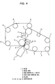
- dewatering equipments 9, 10, 11, and 12 and a vacuum unit 13 are arranged along the traveling paths of wires 1 and 2, as shown in Fig. 4.
- the dewatering equipments 9, 10, 11, and 12 are used for applying dewatering pressure on suspension 4 held between the wires 1, 2.
- the dewatering equipment 9 is arranged opposite a forming roll 5.
- a blade member 8 provided on the tip end of the dewatering equipment 9 is pressed against the forming roll 5 to apply pulse-dewatering pressure on the forming roll 5.
- wires 1, 2 are both in the form of a loop and are guided by a plurality of rolls 6, 7.
- the suspension 4 is squirted from a head box 3 onto the forming roll 5 and is held in a wedge-shaped gap formed by the wires 1, 2.
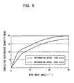
- Fig. 5 is a simplified diagram for explaining how dewatering is performed at the suction forming roll shown in Fig. 4, and Fig. 6 is a distribution diagram of a cumulative quantity to be dewatered to the opposite side of the suction forming roll of Fig. 4.
- the forming roll 5 is the first dewatering part of the former, so a quantity to be dewatered from the suspension 4 at the forming roll 5 is extremely great. Particularly, within a wire warp angle of 10 degrees, about 25% of the flow rate squirted from the head box 3 is dewatered to the opposite side of the forming roll 5, as shown in Fig. 6.
- White water dewatered to the forming roll side is suctioned by the suction box 10 of the forming roll 5, but white water 15 dewatered to the opposite side scatters along the traveling direction of the wires 1, 2, as shown by arrows in Fig. 6.
- the present invention has been made in view of the above-described problems. Accordingly, it is the object of the present invention to provide a twin wire former that is capable of manufacturing defect-free paper that has even dispersion of fibers, while preventing damage to blades that is caused by a collision with white water during dewatering.
- a twin wire former according to the present invention is equipped with white-water withdrawal means for withdrawing white water dewatered to the opposite roll side, which is arranged to the upstream side of a pressure element.
- the present invention is applied to twin wire formers in which (1) a suspension of fibers is supplied between first and second looped wires arranged opposite each other, (2) the looped interior surface of the first wire and the looped exterior surface of the second wire run around a roll, and (3) a pressure element for applying dewatering pressure on the looped interior surface of the secondwire is arranged on the looped interior surface side of the second wire and opposite the roll.
- the twin wire former of the present invention white water dewatered to the opposite roll side is withdrawn by white-water withdrawal means, whereby the interference of white water with the pressure element can be suppressed.
- This can avoid deformation of the pressure element and a bite into the roll due to the deformation.
- white water colliding with the tip end of the pressure element can be prevented from entering between the pressure element and the wire and causing a defect in paper such as streaks.
- damage to the pressure element can be prevented, defect-free and high-quality paper with uneven dispersion of fibers can be manufactured, and stable operation becomes possible.
- the white-water withdrawal means be provided in the forefront pressure element.
- the forefront pressure element is the most influenced by white water. Therefore, if the white-water withdrawal means is provided in the forefront pressure element, the interference between the forefront pressure element and white water is suppressed and problems due to the interference can be prevented.
- a simple example of the white-water withdrawal means is a blade. That is, the blade is arranged inside the second wire and opposite the roll. This blade is not for the purpose of applying dewatering pressure on the looped interior surface of the second wire like the pressure element, but for the purpose of guiding and withdrawing white water in a direction away from the second wire along the blade surface and preventing white water from colliding with the pressure element. Therefore, the white-water withdrawal blade can be arranged at a position farther away from the second wire than the pressure element. It is also preferable that the withdrawal blade be higher in rigidity than the blade used as the pressure element (note that it is preferable that the pressure element have flexibility).
- the white-water withdrawal blade have a tip end curved toward the upstream side to guide white water to the outside along the blade surface so that the white water colliding with the blade tip end does not collide with the wire surface again.
- the white-water withdrawal blade may be equipped with white-water suction means for forcibly suctioning white water withdrawn. By forcibly suctioning white water withdrawn, it can be withdrawn more effectively.
- the white-water suction means can employ a vacuum box, etc.
- the tip end be arranged at a position about 15 mm away from the second wire. If the white-water withdrawal blade is too away from the first wire the efficiency of withdrawing white water declines, and if the white-water withdrawal blade is pressed into the first wire (that is, if distance becomes negative) there are cases where streaks due to the entry of white water occur and the white-water withdrawal blade itself is deformed.
- position adjustment means so that the position of the white-water withdrawal blade in the roll direction can be freely adjusted to a position where white water is efficiently withdrawn. Note that white water dewatered to the opposite roll side applies pressure on the white-water withdrawal blade.
- This pressure varies with the position in the roll direction of the white-water withdrawal blade.
- the tip end be about 1 mm pressed into the interior surface of the first wire toward the roll side so that fibers can be dispersed by the application of pressure.
- position adjustment means so that the position of the pressure element in the roll direction can be freely adjusted to a position where proper fiber dispersion can be performed. More preferably, by providing pressure detection means for detecting pressure that acts on the pressure element, the position of the pressure element in the roll direction is adjusted and moved so that the detected pressure is proper pressure.
- the pressure detection means can employ an ordinary pressure sensor.
- a pressure sensor is provided in the white-water withdrawal blade or pressure element
- pressure acting on the white-water withdrawal blade or pressure element can be directly detected.
- the reaction to the pressure acting on the white-water withdrawal blade and pressure element acts on the surface of the roll.
- the pressure that acts on the white-water withdrawal blade and pressure element may be indirectly detected from the pressure acting on the roll surface through white water, wires, and a suspension of fibers.
- the above-described roll opposite which the pressure element and white-water withdrawal blade are arranged may be a solid roll, a roll with a porous band wrapped around the surface to withdraw surplus white water, or a roll with various grooves in the surface.
- the roll be a suction forming roll.
- white water dewatered to the roll side can be forcibly suctioned, and consequently, the quantity of white water to be dewatered to the opposite roll side because of the influence of centrifugal force can be reduced.
- papermaking can be performed by the following methods. That is, paper is manufactured by detecting pressure that acts on a white-water withdrawal blade by pressure detection means, and adjusting the position of the white-water withdrawal blade in the roll direction by position adjustment means so that the detected pressure is within a proper range. According to this papermaking method, the entry of white water to the tip end of the pressure element is surely prevented and defect-free and high-quality paper with even dispersion of fibers can be manufactured.
- Paper can also be manufactured by detecting pressure that acts on the white-water withdrawal blade by first pressure detection means and also detecting pressure that acts on the pressure element by second pressure detection means, and adjusting the position of the white-water withdrawal blade in the roll direction by first position adjustment means so that the detected pressure is within a first proper range and also adjusting the position of the pressure element in the roll direction by second position adjustment means so that the detected pressure is within a second proper range.
- dewatering pressure to be applied by the pressure element can be made proper and high-quality paper with even dispersion of fibers can be manufactured.
- Fig. 1 is a side view showing the principal part of a twin wire former constructed in accordance with a first embodiment of the present invention. Note in the figure that the same parts as the conventional twin wire former shown in Fig. 4 are represented by the same reference numerals.
- a pair of wires 1, 2 run around a forming roll 5 and are both in the form of a loop.
- the looped interior surface of one (first wire 1) of the two wires runs around the forming roll 5, while the looped exterior surface of the other wire (second wire 2) runs around the forming roll 5.
- a suction box 10 Within the range that the wires 1, 2 run around the forming roll 5 (wire wrap range), there is provided a suction box 10.
- a plurality of flexible loadable blades (pressure elements) 30 are arranged along the direction in which the wires 1, 2 travel.
- These loadable blades 30, 30 constitute a dewatering equipment, which disperses fibers evenly by applying pulse-dewatering pressure on a fiber suspension 4 which is a raw material liquid held between the wires 1 and 2.
- a deflector blade (white-water withdrawal blade) 20 for withdrawing white water 15 is arranged upstream in close proximity to the forefront loadable blade 30.
- This white-water withdrawal blade 20 has a tip end gently curved toward the upstream side and is higher in rigidity than the loadable blade 30.
- the position of the white-water withdrawal blade 20 in the roll direction is set so that the tip end is arranged in close proximity to the interior surface of the wire 2 or contacts the interior surface to the degree of a kiss touch.
- the white-water withdrawal blade 20 is provided with a pressure sensor 40 and a moving device 50 with a displacement sensor for position detection.
- the pressure sensor 40 is a sensor to detect pressure that acts on the white-water withdrawal blade and is primarily used for detecting pressure from white water that collides with the white-water withdrawal blade during dewatering.
- the moving device 50 is a device to move and adjust the position in the roll direction of the white-water withdrawal blade 20 and is able to confirm the current position by the displacement sensor.
- the fiber suspension 4 supplied between the wires 1 and 2 from a head box 3 is transferred onto the suction box 10 while being held between the wires 1 and 2.
- the fiber suspension 4 is dewatered by the surface pressure of the wires 1, 2 and the suction force of the suction box 10.
- dewatering is also performed by the surface pressure of the wires 1, 2 and centrifugal force.
- the dewatered white water 15 is discharged inside the wire 2 along the direction in which the wires 1, 2 travel.
- the twin-wire former of the first embodiment is capable of manufacturing paper of even fiber dispersion that is free from a paper defect such as streaks, while preventing damage to the loadable blades 30 due to a collision with white water 15.
- the white-water withdrawal blade 20 can be adjusted to a proper position by detecting pressure that acts on the white-water withdrawal blade 20 with the pressure sensor 40, and then performing position adjustment with the moving device 50 so that the detected pressure is proper pressure. Since the white-water withdrawal blade 20 has no purpose of enhancing dispersion of fibers, there is no need to generate high dewatering pressure in the fiber suspension 4. The proper position of the white-water withdrawal blade 20 and position control method will be described later (in a second embodiment). However, as at least described above, if the position of the white-water withdrawal blade 20 is adjusted so that it is arranged very close to the wire 2 or contacts the wire 2 to the degree of a kiss touch, there is no possibility that the white-water withdrawal blade 20 will be pressed against the wire 2.
- Fig. 2 is a side view showing the principal part of a twin wire former constructed in accordance with a second embodiment of the present invention. Note in the figure that the same parts as the first embodiment are represented by the same reference numerals.
- flexible loadable blades 35, 36, and 37 arranged in the traveling direction of a wire 2 are respectively provided with white-water withdrawal blades 25, 26, and 27, as shown in Fig. 2.
- the white-water withdrawal blades 25, 26, and 27 are arranged upstream in close proximity to the corresponding loadable blades 35, 36, and 37 and are fixed to moving devices 55, 56, and 57 along with the corresponding loadable blades 35, 36, and 37.
- Each of the moving devices 55, 56, and 57 has a displacement sensor.
- three units 65, 66, and 67 which consist of the loadable blade, white-water withdrawal blade, and moving device, are arranged along the traveling direction of the wire 2.
- white water 15 dewatered to the opposite side of the forming roll 5 is withdrawn by the units 65, 66, and 67.
- the cumulative amount of white water 15 dewatered is maximum at the forefront loadable blade 35, but dewatering of white water 15 is also performed between the loadable blades 35 and 36 and between the loadable blades 36 and 37. Therefore, since the units 65, 66, and 67 are provided with white-water withdrawal blades 25, 26, and 27 for withdrawing white water 15, the white water 15 dewatered between the loadable blades 35 and 36 and between the loadable blades 36 and 37 can be prevented from colliding with the loadable blades 36, 37. This makes it possible to prevent damage to these loadable blades 36, 37 and to manufacture paper that has even dispersion of fibers.
- a pressure sensor 60 is arranged inside the forming roll 5 to detect roll-surface pressure.
- the pressure sensor 60 rotates integrally with the forming roll 5 and serially detects pressure that acts at each position in the circumferential direction.
- the reaction to the pressure acting on the white-water withdrawal blades 25, 26, 27 and loadable blades 35, 36, 37 acts on the surface of the forming roll 5.
- the pressure that acts on the white-water withdrawal blades 25, 26, 27 and loadable blades 35, 36, 37 can be indirectly detected.
- Fig. 3 is an explanatory diagram for explaining a method of controlling positions of the white-water withdrawal blades 25, 26, 27 and loadable blades 35, 36, 37.
- Fig. 3A is a diagram showing the relationship between a distance d from the roll surface to each blade tip end and the roll surface pressure
- Fig. 3B is a simplified diagram for explaining the definition of the distance d shown in Fig. 3A. Note that the position control method hereinafter described can also be applied to the position control of the white-water withdrawal blade 20 of the first embodiment.
- the reference position is away from the surface of the forming roll 5 by the sum of the thickness of the two wires 1, 2 and the thickness of the fiber suspension 4 held between the wires 1, 2. More specifically, the proper positions are in a range of 0 to 15 mm from the reference position (interior surface of the wire 2).
- proper positions of the loadable blades 35, 36, and 37 are within an inter wire deformation region from the above-described reference position as shown by a white bar in Fig. 3A, because they must compress the fiber suspension 4 held between the wires 1 and 2 to disperse fibers. More specifically, the proper positions are in a range of 1 to 3 mm from the reference position toward the forming roll 5.
- the position control of the white-water withdrawal blades 25, 26, 27 and loadable blades 35, 36, 37 is performed based on values detected by the pressure sensor 60 provided in the forming roll 5. That is, a pressure diagram such as that shown by a solid line in Fig. 3A is previously prepared and a proper pressure range corresponding to proper positions is computed. And by controlling the moving devices 55, 56, and 57 so that values detected by the pressure sensor 60 are within the proper pressure range, the positions of the white-water withdrawal blades 25, 26, 27 and loadable blades 35, 36, 37 are adjusted.
- the above-described position control can be performed automatically, or it can be performed manually by an operator. In the case of automatic control, the pressure diagram is previously stored in a controller, and signals from the moving devices 55, 56, and 57 are fed back to the controller so that values detected by the pressure sensor 60 are within the proper pressure range.
- the dewatering pressure to be applied by the loadable blades 35, 36, 37 can be made optimum.
- the occurrence of streaks due to the entry of white water into the space between the loadable blade (35, 36, or 37) and the wire 2 can be surely prevented. As a result, it becomes possible to manufacture high-quality paper that has even dispersion of fibers.
- the reference position shown in Fig. 3A (which is away from the surface of the forming roll 5 by the sum of the thickness of the two wires 1, 2 and the thickness of the fiber suspension 4 between the wires 1, 2) moves closer to the surface of the forming roll 5 toward the downstream side. Therefore, the pressure diagram shown in Fig. 3A varies with blade positions. Hence, to perform accurate position control, it is preferable to previously input a pressure diagram corresponding to each blade to a controller.
- each of the blades 25, 26, 27, 35, 36, and 37 may be provided with a pressure sensor so that optimum position control can be performed based on values detected by the pressure sensor.
- a plurality of white-water withdrawal blades may be arranged to the upstream side of each blade or blade group.
- each white-water withdrawal blade may be provided with suction means (such as a suction box, etc.) so that the white water withdrawn by the blade can be forcibly suctioned. Withdrawn white water can be continuously removed to the outside, so it becomes possible to withdraw white water more efficiently.
- suction means such as a suction box, etc.
- the white-water withdrawal means of the present invention is not to be limited to the blades constructed in accordance with the above-described embodiments.
- the white-water withdrawal means may have any shape if it can prevent the white water withdrawn to the opposite side of the forming roll 5 from colliding with loadable blades. Therefore, for example, it may have a shape that becomes thicker in the traveling direction of the wire, or it may have a guide plate shape if rigidity is assured.
- the pressure elements are not to be limited to the blades constructed in accordance with the above-described embodiments. They may be roll members or rod members , if they can applypulse-dewatering pressure on the fiber suspension held between the wires. In the case of blades, they may be not a flexible type like the embodiments, but a fixed type.
Landscapes
- Paper (AREA)
Abstract
Description
Claims (12)
- A twin wire former for supplying a suspension of fibers between first and second looped wires arranged opposite each other, and dewatering said suspension of fibers held between said first and second wires, running a looped interior surface of said first wire and a looped exterior surface of said second wire around a roll, said former comprising:a pressure element, arranged on the looped interior surface side of said second wire and opposite said roll, for applying dewatering pressure on the looped interior surface of said second wire; andwhite-water withdrawal means arranged to the upstream side of said pressure element for withdrawing white water dewatered to the looped interior surface side of said second wire.
- The twin wire former as set forth in claim 1, wherein:said pressure element comprises a plurality of pressure elements arranged along a direction in which said second wire travels; andsaid white-water withdrawal means is provided in the forefront pressure element of said pressure element group.
- The twin wire former as set forth in claim 1 or 2, wherein said white-water withdrawal means comprises a white-water withdrawal blade arranged on the looped interior surface side of said second wire and opposite arranged said roll.
- The twin wire former as set forth in claim 3, wherein said white-water withdrawal blade has a tip end curved toward an upstream side.
- The twin wire former as set forth in claim 3 or 4, further comprising white-water suction means for suctioning white water withdrawn by said white-water withdrawal blade.
- The twin wire former as set forth in any one of claims 3 through 5, further comprising first position adjustment means for adjusting the position of said white-water withdrawal blade in the direction of said roll.
- The twin wire former as set forth in claim 6, further comprising first pressure detection means for detecting pressure that acts on said white-water withdrawal blade.
- The twin wire former as set forth in claim 6 or 7, further comprising second position adjustment means for adjusting the position of said pressure element in said roll direction.
- The twin wire former as set forth in claim 8, further comprising second pressure detection means for detecting pressure that acts on said pressure element.
- The twin wire former as set forth in any one of claims 1 through 9, wherein said roll comprises a suction forming roll.
- A method of manufacturing paper by employing the twin wire former as set forth in claim 7, comprising the steps of:detecting pressure that acts on saidwhite-water withdrawal blade by said first pressure detection means; andadjusting the position of said white-water withdrawal blade in said roll direction by said first position adjustment means so that the detected pressure is within a proper range.
- A method of manufacturing paper by employing the twin wire former as set forth in claim 9, comprising the steps of:detecting pressure that acts on saidwhite-water withdrawal blade by said first pressure detection means and also detecting pressure that acts on said pressure element by said second pressure detection means; andadjusting the position of said white-water withdrawal blade in said roll direction by said first position adjustment means so that the detected pressure is within a first proper range, and also adjusting the position of said pressure element in said roll direction by said second position adjustment means so that the detected pressure is within a second proper range.
Applications Claiming Priority (3)
| Application Number | Priority Date | Filing Date | Title |
|---|---|---|---|
| JP2002034501 | 2002-02-12 | ||
| JP2002034501A JP2003239187A (en) | 2002-02-12 | 2002-02-12 | Twin-wire paper machine |
| PCT/JP2003/001386 WO2003069058A1 (en) | 2002-02-12 | 2003-02-10 | Twin-wire paper machine |
Publications (3)
| Publication Number | Publication Date |
|---|---|
| EP1484444A1 true EP1484444A1 (en) | 2004-12-08 |
| EP1484444A4 EP1484444A4 (en) | 2005-08-17 |
| EP1484444B1 EP1484444B1 (en) | 2006-12-20 |
Family
ID=27678029
Family Applications (1)
| Application Number | Title | Priority Date | Filing Date |
|---|---|---|---|
| EP03703306A Expired - Lifetime EP1484444B1 (en) | 2002-02-12 | 2003-02-10 | Twin-wire paper machine |
Country Status (6)
| Country | Link |
|---|---|
| US (1) | US20050103460A1 (en) |
| EP (1) | EP1484444B1 (en) |
| JP (1) | JP2003239187A (en) |
| CA (1) | CA2476233A1 (en) |
| DE (1) | DE60310534T2 (en) |
| WO (1) | WO2003069058A1 (en) |
Family Cites Families (7)
| Publication number | Priority date | Publication date | Assignee | Title |
|---|---|---|---|---|
| US4028175A (en) * | 1974-03-13 | 1977-06-07 | J. M. Voith Gmbh | Cylinder machine having positive pressure chambers adjacent an outer band |
| US4235667A (en) * | 1979-04-09 | 1980-11-25 | Beloit Corporation | Method of and means for attaining uniformity in paper webs produced on a roll former |
| JPS599679B2 (en) * | 1979-11-19 | 1984-03-03 | ベロイト コ−ポレ−ション | Web forming device for paper machine |
| US5211814A (en) * | 1991-05-31 | 1993-05-18 | Valmet Paper Machinery Inc. | Wire loading device in a paper machine |
| DE4301103C1 (en) * | 1993-01-18 | 1994-08-18 | Voith Gmbh J M | Screen section of a paper machine |
| JPH06341090A (en) * | 1993-05-27 | 1994-12-13 | Mitsubishi Heavy Ind Ltd | Twin-wire device |
| CA2247085A1 (en) * | 1996-12-23 | 1998-07-02 | Voith Sulzer Papiermaschinen Gmbh | Wet end, method for the production of a fibrous material web and use of wet end |
-
2002
- 2002-02-12 JP JP2002034501A patent/JP2003239187A/en not_active Withdrawn
-
2003
- 2003-02-10 CA CA002476233A patent/CA2476233A1/en not_active Abandoned
- 2003-02-10 WO PCT/JP2003/001386 patent/WO2003069058A1/en not_active Ceased
- 2003-02-10 EP EP03703306A patent/EP1484444B1/en not_active Expired - Lifetime
- 2003-02-10 US US10/504,268 patent/US20050103460A1/en not_active Abandoned
- 2003-02-10 DE DE60310534T patent/DE60310534T2/en not_active Expired - Fee Related
Non-Patent Citations (2)
| Title |
|---|
| No further relevant documents disclosed * |
| See also references of WO03069058A1 * |
Also Published As
| Publication number | Publication date |
|---|---|
| CA2476233A1 (en) | 2003-08-21 |
| DE60310534T2 (en) | 2007-10-31 |
| JP2003239187A (en) | 2003-08-27 |
| US20050103460A1 (en) | 2005-05-19 |
| WO2003069058A1 (en) | 2003-08-21 |
| DE60310534D1 (en) | 2007-02-01 |
| EP1484444A4 (en) | 2005-08-17 |
| EP1484444B1 (en) | 2006-12-20 |
Similar Documents
| Publication | Publication Date | Title |
|---|---|---|
| EP1543194B1 (en) | Forming of a paper or board web in a twin-wire former | |
| US6521089B1 (en) | Process for controlling or regulating the basis weight of a paper or cardboard web | |
| JP2836907B2 (en) | Web forming method and apparatus | |
| KR20010020613A (en) | Apparatus and method for winding paper | |
| US8444824B2 (en) | Paper or board machine employing a single-wire draw dryer section | |
| US10094058B2 (en) | Method and apparatus for guiding a nonwoven web | |
| US7597778B2 (en) | Method for the production of a web of tissue material | |
| US4014740A (en) | Structure for transferring a web from the press section to the drying section of a paper machine | |
| EP1073789B1 (en) | System of regulation for a paper machine | |
| US20030155395A1 (en) | Method and equipment in connection with a paper machine or a paper web finishing apparatus | |
| JP3518867B2 (en) | Assembly for paper web coating line | |
| EP1122361B1 (en) | Transfer of a lead strip of a paper web | |
| EP1484444B1 (en) | Twin-wire paper machine | |
| CN215976628U (en) | Steering system for fiber webs in the forming section of a fiber web production machine | |
| CA2168119C (en) | Gap former in a paper machine | |
| US6464835B1 (en) | Equipment and method in a twin-wire former | |
| US20060102309A1 (en) | Arrangement in the on-line finisching of the paper machine | |
| CA2302159C (en) | Method and arrangement for guiding a paper or board web | |
| EP1556545A1 (en) | Method and arrangement for calendering a web | |
| FI20205551A1 (en) | Forming section of a fiber web production line | |
| US20060102019A1 (en) | Method and arrangement for calendering a web |
Legal Events
| Date | Code | Title | Description |
|---|---|---|---|
| PUAI | Public reference made under article 153(3) epc to a published international application that has entered the european phase |
Free format text: ORIGINAL CODE: 0009012 |
|
| 17P | Request for examination filed |
Effective date: 20040903 |
|
| AK | Designated contracting states |
Kind code of ref document: A1 Designated state(s): AT BE BG CH CY CZ DE DK EE ES FI FR GB GR HU IE IT LI LU MC NL PT SE SI SK TR |
|
| AX | Request for extension of the european patent |
Extension state: AL LT LV MK RO |
|
| RIN1 | Information on inventor provided before grant (corrected) |
Inventor name: IWATA, HIROSHIC/O PAPER & PRINTING MACHINERY D Inventor name: MATSUMOTO,MASANOBUPAPER & PRINTING MACHINERY D Inventor name: IBUSHI,JUNICHIC/O PAPER & PRINTING MACHINERY D Inventor name: MASUDA, KAZUHIKO;PAPER & PRINTING MACHINERY DI |
|
| RIN1 | Information on inventor provided before grant (corrected) |
Inventor name: MATSUMOTO,MASANOBUPAPER & PRINTING MACHINERY D Inventor name: IBUSHI,JUNICHIC/O PAPER & PRINTING MACHINERY D Inventor name: MASUDA, KAZUHIKOPAPER & PRINTING MACHINERY DIV Inventor name: IWATA, HIROSHIC/O PAPER & PRINTING MACHINERY D |
|
| A4 | Supplementary search report drawn up and despatched |
Effective date: 20050704 |
|
| RIC1 | Information provided on ipc code assigned before grant |
Ipc: 7D 21F 9/00 B Ipc: 7D 21F 9/02 A |
|
| GRAP | Despatch of communication of intention to grant a patent |
Free format text: ORIGINAL CODE: EPIDOSNIGR1 |
|
| GRAS | Grant fee paid |
Free format text: ORIGINAL CODE: EPIDOSNIGR3 |
|
| GRAA | (expected) grant |
Free format text: ORIGINAL CODE: 0009210 |
|
| AK | Designated contracting states |
Kind code of ref document: B1 Designated state(s): DE FI FR GB IT |
|
| REG | Reference to a national code |
Ref country code: GB Ref legal event code: FG4D |
|
| REF | Corresponds to: |
Ref document number: 60310534 Country of ref document: DE Date of ref document: 20070201 Kind code of ref document: P |
|
| EN | Fr: translation not filed | ||
| PLBE | No opposition filed within time limit |
Free format text: ORIGINAL CODE: 0009261 |
|
| STAA | Information on the status of an ep patent application or granted ep patent |
Free format text: STATUS: NO OPPOSITION FILED WITHIN TIME LIMIT |
|
| 26N | No opposition filed |
Effective date: 20070921 |
|
| GBPC | Gb: european patent ceased through non-payment of renewal fee |
Effective date: 20070320 |
|
| PG25 | Lapsed in a contracting state [announced via postgrant information from national office to epo] |
Ref country code: FR Free format text: LAPSE BECAUSE OF FAILURE TO SUBMIT A TRANSLATION OF THE DESCRIPTION OR TO PAY THE FEE WITHIN THE PRESCRIBED TIME-LIMIT Effective date: 20070810 Ref country code: GB Free format text: LAPSE BECAUSE OF NON-PAYMENT OF DUE FEES Effective date: 20070320 |
|
| PG25 | Lapsed in a contracting state [announced via postgrant information from national office to epo] |
Ref country code: FR Free format text: LAPSE BECAUSE OF FAILURE TO SUBMIT A TRANSLATION OF THE DESCRIPTION OR TO PAY THE FEE WITHIN THE PRESCRIBED TIME-LIMIT Effective date: 20061220 |
|
| PGFP | Annual fee paid to national office [announced via postgrant information from national office to epo] |
Ref country code: DE Payment date: 20090219 Year of fee payment: 7 Ref country code: FI Payment date: 20090217 Year of fee payment: 7 |
|
| PGFP | Annual fee paid to national office [announced via postgrant information from national office to epo] |
Ref country code: IT Payment date: 20090220 Year of fee payment: 7 |
|
| REG | Reference to a national code |
Ref country code: FR Ref legal event code: TP |
|
| REG | Reference to a national code |
Ref country code: FR Ref legal event code: TP |
|
| PG25 | Lapsed in a contracting state [announced via postgrant information from national office to epo] |
Ref country code: FI Free format text: LAPSE BECAUSE OF NON-PAYMENT OF DUE FEES Effective date: 20100210 |
|
| PG25 | Lapsed in a contracting state [announced via postgrant information from national office to epo] |
Ref country code: DE Free format text: LAPSE BECAUSE OF NON-PAYMENT OF DUE FEES Effective date: 20100901 |
|
| PG25 | Lapsed in a contracting state [announced via postgrant information from national office to epo] |
Ref country code: IT Free format text: LAPSE BECAUSE OF NON-PAYMENT OF DUE FEES Effective date: 20100210 |