EP1484205A2 - Vehicle suspension damper with integral height levelling valve - Google Patents
Vehicle suspension damper with integral height levelling valve Download PDFInfo
- Publication number
- EP1484205A2 EP1484205A2 EP04253247A EP04253247A EP1484205A2 EP 1484205 A2 EP1484205 A2 EP 1484205A2 EP 04253247 A EP04253247 A EP 04253247A EP 04253247 A EP04253247 A EP 04253247A EP 1484205 A2 EP1484205 A2 EP 1484205A2
- Authority
- EP
- European Patent Office
- Prior art keywords
- housing
- valve
- rotating
- damper assembly
- height
- Prior art date
- Legal status (The legal status is an assumption and is not a legal conclusion. Google has not performed a legal analysis and makes no representation as to the accuracy of the status listed.)
- Granted
Links
Images


Classifications
-
- B—PERFORMING OPERATIONS; TRANSPORTING
- B60—VEHICLES IN GENERAL
- B60G—VEHICLE SUSPENSION ARRANGEMENTS
- B60G17/00—Resilient suspensions having means for adjusting the spring or vibration-damper characteristics, for regulating the distance between a supporting surface and a sprung part of vehicle or for locking suspension during use to meet varying vehicular or surface conditions, e.g. due to speed or load
- B60G17/02—Spring characteristics, e.g. mechanical springs and mechanical adjusting means
- B60G17/04—Spring characteristics, e.g. mechanical springs and mechanical adjusting means fluid spring characteristics
- B60G17/052—Pneumatic spring characteristics
- B60G17/0521—Pneumatic spring characteristics the spring having a flexible wall
-
- B—PERFORMING OPERATIONS; TRANSPORTING
- B60—VEHICLES IN GENERAL
- B60G—VEHICLE SUSPENSION ARRANGEMENTS
- B60G11/00—Resilient suspensions characterised by arrangement, location or kind of springs
- B60G11/26—Resilient suspensions characterised by arrangement, location or kind of springs having fluid springs only, e.g. hydropneumatic springs
- B60G11/27—Resilient suspensions characterised by arrangement, location or kind of springs having fluid springs only, e.g. hydropneumatic springs wherein the fluid is a gas
-
- B—PERFORMING OPERATIONS; TRANSPORTING
- B60—VEHICLES IN GENERAL
- B60G—VEHICLE SUSPENSION ARRANGEMENTS
- B60G17/00—Resilient suspensions having means for adjusting the spring or vibration-damper characteristics, for regulating the distance between a supporting surface and a sprung part of vehicle or for locking suspension during use to meet varying vehicular or surface conditions, e.g. due to speed or load
- B60G17/02—Spring characteristics, e.g. mechanical springs and mechanical adjusting means
- B60G17/04—Spring characteristics, e.g. mechanical springs and mechanical adjusting means fluid spring characteristics
- B60G17/048—Spring characteristics, e.g. mechanical springs and mechanical adjusting means fluid spring characteristics with the regulating means inside the fluid springs
- B60G17/0485—Spring characteristics, e.g. mechanical springs and mechanical adjusting means fluid spring characteristics with the regulating means inside the fluid springs the springs being pneumatic springs with a flexible wall, e.g. with levelling valves
-
- B—PERFORMING OPERATIONS; TRANSPORTING
- B60—VEHICLES IN GENERAL
- B60G—VEHICLE SUSPENSION ARRANGEMENTS
- B60G2202/00—Indexing codes relating to the type of spring, damper or actuator
- B60G2202/30—Spring/Damper and/or actuator Units
- B60G2202/31—Spring/Damper and/or actuator Units with the spring arranged around the damper, e.g. MacPherson strut
- B60G2202/314—The spring being a pneumatic spring
-
- B—PERFORMING OPERATIONS; TRANSPORTING
- B60—VEHICLES IN GENERAL
- B60G—VEHICLE SUSPENSION ARRANGEMENTS
- B60G2204/00—Indexing codes related to suspensions per se or to auxiliary parts
- B60G2204/10—Mounting of suspension elements
- B60G2204/11—Mounting of sensors thereon
- B60G2204/111—Mounting of sensors thereon on pneumatic springs
Definitions
- This invention relates to vehicle suspension dampers and more particularly to vehicle suspension dampers with a height leveling capability.
- Pneumatic height leveling valves used in air suspension systems maintain a pre-determined ride height by regulating the pressurized air within an air spring system.
- Conventional systems utilize an external height leveling valve to control the amount of air in and out of the air spring.
- remote valves require additional packaging space within the vehicle.
- an external valve may be adversely affected by dirt and moisture as the valve may be relatively exposed to the environment.
- Integral height leveling valves are becoming more widely known, but commonly provide a relatively complex piston and sleeve arrangement which envelops a vast majority of the damper body. A relatively thick piston and sleeve arrangement covers a large portion of the damper which may result in poor heat dissipation.
- Conventional internal height leveling valves also typically utilize a linear placement of the valve mechanism. Such a linear placement may introduce a significant amount of dead-length within the damper which may prohibit articulations of the damper under certain vehicle geometries.
- the present invention provides a height leveling valve for use in a vehicle having an air spring suspension.
- the suspension is adjusted to a predetermined height such that the vehicle is relatively level.
- the height leveling valve brings the vehicle level once again by regulating fluid pressure within the suspension to return the suspension to the predetermined height.
- the height leveling valve of the present invention may be incorporated into an air spring shock module or a shock absorber.
- a cylinder contains a piston, as generally known in the art.
- a piston rod extends from the cylinder into a first housing.
- a second housing surrounds the cylinder.
- the first and second housings can telescope relative to each other.
- An actuating member such as a cable is connected to the valve.
- the height leveling valve can be contained in either the first or the second housing. This compact arrangement aids in heat dissipation.
- the actuating member is attached to a rotating cam, a rotating valve plate or a rotating valve.
- the actuating member winds around a spool that is connected to the cam, rotating valve plate or rotating valve such that changes in the unwound length of the actuating member rotates the cam, rotating valve plate or rotating valve in one direction or the other.
- the cam directly activates radial or axially located spring biased inlet and exhaust valves or else a sliding valve plate.
- a sliding valve plate sits adjacent the rotating cam and includes an inlet and an exhaust flow path which can be aligned with a corresponding inlet or exhaust flow path through the port valves contained in the first or second housing.
- a return spring biases the valve plate toward the cam such that rotation of the cam displaces the valve plate to selectively open and close the inlet and exhaust flow paths.
- valve plate which contains inlet and exhaust flow paths.
- actuating member activates a rotating valve then port valves located to a radial dimension about the rotating valve axis contact the rotating valve which contains inlet and exhaust flow paths.
- the inlet and exhaust flow paths are selectively opened and closed as the rotating valve plate or rotating valve is rotated under the control of the actuating member to align the inlet or exhaust flow paths through the port valves in the first or second housing with the corresponding inlet or exhaust flow path through the rotating valve plate or valve.
- Using fewer parts reduces the cost of the valve assembly with respect to other integral height leveling valves.
- the present invention therefore provides a damper assembly with a compact integral height leveling valve which maximizes heat dissipation, and is cost effective.
- the present invention could also be part of an air spring assembly in which no shock absorber is involved or could be used separate from an air spring, air spring shock module or shock absorber as a separate height leveling valve attached between a fixed suspension member and a suspension member that telescopes relative to the fixed member.
- a vehicle 10 having an air spring suspension 12 is shown in Figures 1A and 1B.
- the suspension is adjusted to a predetermined height h, wherein the fluid pressure within the suspension 12 falls within an acceptable range such that the vehicle 10 is relatively level.
- the vehicle is in a loaded condition, which can occur, for example, if an unevenly distributed load is placed on the vehicle 10. When this occurs, the suspension 12 falls below the acceptable range and the vehicle 10 is not level.
- a height leveling valve functions to bring the vehicle 10 level once again by adding fluid pressure within the suspension 12 to return the suspension 12 to the predetermined height h. Similarly, if load is removed from a vehicle 10, the suspension 12 would rise above the acceptable level and the height leveling valve will release fluid pressure from the air spring suspension 12 to bring the vehicle 10 level once again.
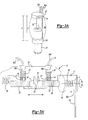
- FIG 2 is a perspective view of the present invention in which a height leveling valve 14 (shown schematically in Figure 2 and in detail in Figure 3A') is incorporated into the upper end of a damper such as an air spring shock module 16.
- a damper such as an air spring shock module 16.
- a cylinder 18 contains a piston p as generally known in the art.
- a piston rod 20 extends from the cylinder 18 into a first housing 22, which is also the upper end of the air spring shock module 16.
- a second housing 24 surrounds the cylinder 18. The second housing 24 is preferably a slip on component.
- An air bag (partially illustrated at 26) is attached to the first housing 22 and the second housing 24 to create an air chamber c as known in the art.
- Inlet and exhaust air lines 562, 564 attach to the first housing 22.
- An actuating member 28 is connected to the valve 14.
- the actuating member 28 is preferably flexible such as a cable, wire, rope or other member which can be wrapped around a rotating cam 30 ( Figure 3A').
- the height leveling valve 14 is preferably contained within the first housing 22.
- the actuating member 28 extends from the first housing 22 and is fixed to the second housing 24. When the vehicle is at ride height, corresponding to a specific distance between the first and second housings, the actuating member 28 allows the valve 14 to be closed and to neither add nor remove air from the vehicle air suspension to adjust vehicle height.
- Making fine adjustments to the actuating member 28 unwound length at this valve 14 closed condition makes fine adjustments to the ride height of the air suspension for a particular vehicle. In a preferred embodiment this may be done by an adjusting screw at the point of attachment of the actuating member 28 to the second housing 24.
- any means of making fine adjustments to the unwound length of actuating member 28 may be used in the first or second housing.
- Figure 3A' is an exploded partial sectional view of the integral height leveling valve 14.
- the actuating member 28 is attached to the rotating cam 30.
- the actuating member 28 winds around a spool portion 560 connected to the cam 30 such that changes in the unwound length of the actuating member 28 allow rotation of the cam 30 about axis C in one direction or the other.
- a sliding valve plate 32 sits adjacent the rotating cam 30, while a return spring 34 biases the sliding valve plate 32 toward the cam 30 such that rotation of the cam 30 linearly displaces the sliding valve plate 32 as shown by the double-headed arrow in Figure 3A'.
- the sliding valve plate 32 includes an inlet flow path 36 and an exhaust flow path 38 both of which pass through the sliding valve plate. There is a corresponding inlet flow path 566 and exhaust flow path 568 in the first housing 22.
- the flow paths 566, 568 contain inlet and exhaust port valves 40, 41 with inlet and exhaust port valve pre-load springs 42, 43 to seal the flow paths 566, 568 against the sliding valve plate 32 when they are not aligned with flow paths 36, 38.
- the port valves 40, 41 outside diameters may be sealed to the first or second housing counter-bores they are contained in by use of a dynamic seal S'" such as an o-ring.
- a dynamic seal S' such as an o-ring.
- any method of sealing the flow paths 566, 568 to the sliding valve plate 32 may be utilized.
- the sliding valve plate 32 further includes an opening 44 to receive a retaining pin 46 that connects into housing 22.
- the valve 14 is at a radial offset to one side from the center of the first housing 22 away from the central location where the piston rod 20 attaches to the first housing 22.
- An inlet air line 562 complete with fitting connects with inlet flow path 566 in the housing 22 to convey air pressure from the vehicle supply source into the air spring shock module and in a preferred embodiment an exhaust air line 564, which may include a muffler to reduce exhaust air flow noise, connects with exhaust flow path 568 in the housing 22 to convey exhaust air flow out to the environment.
- the exhaust flow path 568 may exit directly to the environment with the exhaust flow path 568 sized near its exit from the housing 22 to the environment so as to reduce noise as the exhaust air flow leaves the valve 14.
- a moveable cover such as a flap may be used at the exit of the exhaust flow path 568 to the environment to prevent the entrance of contamination into the valve 14.
- the air spring shock module 16 containing the valve 14 may be connected to one or more air spring shock modules or air springs mounted on the same air suspension but not having height leveling valves of their own. In this way, the valve 14 may control the pressure of all the air spring shock modules or air springs on the air suspension to maintain the vehicle at the predetermined height h ( Figure 1A).
- the air pressure inside chamber c ( Figure 2) of the air spring shock module 16 can be communicated to the other air spring shock modules or air springs on the same air suspension through air lines emerging from housing 22 where the valve 14 is housed or alternatively air lines emerging from housing 24.
- the actuating member 28 locates the cam 30 at a rotational position which linearly locates the valve plate 32 such that both inlet and exhaust flow paths are closed. That is, the current pressure within the air bag 26 ( Figure 2) is maintained.
- the torsion spring 48 (in this case housed within the rotating cam 30) preferably maintains the actuating member 28 in tension.
- the predetermined range h is the vehicle ride height position.
- the actuating member 28 When the distance d falls out of the range h ( Figures 3B and 3C), the actuating member 28 extends or retracts around a spool portion 560 which is connected to the cam 30 against the torsion spring 48 tension to open the necessary flow path to regulate the fluid pressure.
- the distance d is approximately equal to the height h, as shown in Figure 3A.
- the damper height increases or decreases in response to a load on the vehicle 10, thus increasing or decreasing the distance d between the first housing 22 and the second housing 24. If the distance d is less than height h ( Figure 3B), this indicates fluid pressure must be added to the air spring suspension to regain height h with the increased load on the suspension.
- the actuating member 28 allows the torsion spring 48 to rotate the cam 30 to retract the actuating member 28 around the spool portion 560 and to move the sliding valve plate 32 to align the inlet flow paths 36 and 566, thereby allowing fluid to pass through the center of the port valve 40 to enter the air spring to regulate the vehicle height (distance d).
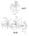
- the valve 14a may also be incorporated into the lower end of an air spring shock module 50, as shown in Figure 4.
- a piston rod 54 extends from the cylinder 52 into a first housing 56.
- a second housing 58 surrounds the cylinder 52.
- An air bag 60 is attached to the first housing 56 and the second housing 58 to create an air chamber.
- the height leveling valve 14a in this embodiment 50 is contained in the second housing 58.
- the actuating member 28a is connected to the cam ( Figure 3A') within the second housing 58 and fixedly connected to the first housing 56. Inlet and exhaust air lines 762, 764 attach to the second housing 58.
- a benefit of having the valve located in the second housing when the valve is controlling the ride height of a truck cabin air spring suspension is easier routing of air lines to the valve and the avoidance of continual air line flexing during cabin suspension movements as would occur if the valve was contained in the first housing.
- This benefit results from inlet supply and exhaust air lines typically being routed on the truck frame which is also the attachment point for the lower end of the air spring shock module.
- the upper end of the air spring shock module would typically connect to the cabin floor.
- FIG. 5 shows a perspective view of the present invention in which the height leveling valve 14b is incorporated into a shock absorber 70.
- a cylinder 72 contains a piston p' as known in the art.
- a piston rod 74 extends from the cylinder 72 into a first housing 76.
- a second housing 78 surrounds the cylinder 72.
- a dust tube (partially shown at 80) is attached to the first housing 76 to prevent dust from collecting on the rod 74.
- any method of keeping dust off the rod 74 may be used.
- the height leveling valve 14b is contained within the first housing 76.
- the actuating member 28b which is connected to the cam ( Figure 3A') within the first housing 76, extends from the first housing 76 and is fixedly connected to the second housing 78. Inlet and exhaust air lines 862, 864 attach to the first housing 76.
- valve assembly 14b When used in a shock absorber, the valve assembly 14b operates to maintain vehicle height through the maintenance of air pressure in a separate air spring in a manner similar to, for example, that described in Figures 3A', 3B' and 3C'. It should be understood that multiple air springs or the like may be controlled remotely by a single valve assembly on a single shock absorber or other member. That is, the one valve assembly on a single air spring member or the like also controls a plurality of air spring members or the like.
- the valve 14b however alternatively or additionally is used to measure the distance d between the housings 76, 78 and then utilize this information to remotely control a variety of remote devices such as an air spring or another device.
- the linear measurement taken from the sliding valve plate or a rotational measurement from the cam is sent to a controller ( Figure 5) and utilized for a variety of applications, i.e. sending distance d to a remote air spring or other device.
- FIG 6 shows another perspective view of the present invention, in which the height leveling valve 14c is incorporated into another shock absorber 90.
- the height leveling valve 14c is contained within the second housing 92 as described with respect to Figure 5.
- Inlet and exhaust air lines 962, 964 attach to the second housing 92.
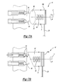
- another integral height leveling valve 14' includes a rotating cam 30' which directly engages an inlet spring biased valve 94 and an exhaust spring biased valve 96.
- the valves 94, 96 are located in an axial direction relative to the rotating cam 30'.
- the rotating cam 30' rotates about a cam axis C.
- the valves 94, 96 may alternatively or additionally include poppet, ball or other valves which are selectively opened by overcoming a spring or other bias. Alternately a single spool valve may be directly activated by the rotating cam 30' and used in place of separate inlet and exhaust valves.
- the rotating cam 30' includes an inclined surface 98 (Figure 8) which does not engage the inlet spring biased valve 94 and the exhaust spring biased valve 96 when the vehicle is at the desired height h ( Figure 1A). Both the inlet spring biased valve 94 and the exhaust spring biased valve 96 are closed ( Figure 7A). When the distance d falls out of the range h ( Figures 7B and 7C), the actuating member 28 retracts around or extends from around the spool portion 660 connected to the cam 30' against the torsion spring 48 tension.
- the cam profile which is inclined surface 98 ( Figure 8) and which activates the valves in a direction parallel to the cam axis C, engages and opens the inlet spring biased valve 94 ( Figure 7B) to increase air pressure in the air spring suspension and increase the vehicle height toward the desired height h.
- the inclined surface 98 engages and opens the exhaust spring biased valve 96 ( Figure 7C) to release air pressure and decrease the vehicle height toward the desired height h.
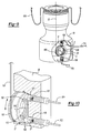
- FIG. 9 An example of a height leveling valve in the second housing 58 onto which the lower end of an air bag 626 is attached similar to that shown in Figure 4 is shown in Figure 9.
- the rotating cam 30' is controlled by actuating member 28 which wraps around a spool portion 660 connected to the cam 30'.
- the actuating member 28 is kept in tension by torsion spring 648 acting on cam 30' and connected spool portion 660.
- the rotating cam 30' radial profile controllably activates inlet spring biased valve 106 and exhaust spring biased valve 108 placed in a radial direction about the cam axis C to control vehicle height depending upon the vehicle loading.
- the height leveling valve is shown in Figure 9 with the air spring shock module at full extension resulting in the exhaust valve 108 being open to release air pressure from the air bag 626 to return the air suspension to ride height. Also as shown in Figure 9 an inlet air line 772 and an exhaust air line 774 are connected to flow passages through the inlet spring biased valve 106 and exhaust spring biased valve 108 respectively at their exits from the lower housing wall.
- a seal S is placed in the first or second housing to contact the spool portion 660 outside diameter at its juncture with the cam 30' to contain pressurized air within the valve.
- the actuating member 28 and spool portion 660 will be at ambient pressure.
- the actuating member 28, spool portion 660 and cam 30' are at ambient pressure where the directly actuated valves 106, 108 ( Figure 9) contain seals S' to isolate the air pressure they control from the ambient.
- the actuating member 128 controls the movement of a rotating valve plate 132.
- the inlet axially orientated spring pre-loaded port valve 116 and exhaust axially orientated spring pre-loaded port valve 118 shown for example as in the housing 58 (similar to that in Figure 4), seal axially against the rotating valve plate 132.
- Dynamic seals S"' such as o'rings can be used to seal the port valves to the housing.
- the air flow openings are preferably arcuate slot-like openings 190, 192 through the rotating valve plate 132. If the vehicle height falls below the desired level the actuating member 128 allows the torsion spring 148 (housed within the rotating valve plate) to rotate the spool portion 155 and connected rotating valve plate 132 to retract the actuating member 128 around the spool portion 155 and to align the flow passage through the inlet port valve 116 with an inlet flow passage 190 in the rotating valve plate 132 to allow inlet air flow.
- the actuating member 128 rotates the spool portion 155 and connected rotating valve plate 132 against the torsion spring 148 tension to extend the actuating member 128 and align the flow passage through the exhaust port valve 118 with an exhaust flow passage 192 in the valve plate to allow exhaust air flow.
- An inlet air line 972 and an exhaust air line 974 are connected to the inlet port valve 116 and exhaust port valve 118 respectively at the points where they exit from the housing. Torsion spring 148 keeps the actuating member in tension.
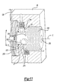
- FIG 11 another arrangement includes an inlet radially orientated spring pre-loaded port valve 216 and an exhaust radially orientated spring pre-loaded port valve 218, shown for example as in the housing 58 (similar to that in Figure 4), having a radial spacing about the rotary valve axis C and which seal against the rotary valve 232 outside diameter surface. Seals S"' such as o'rings can be used to seal the port valves to the housing.
- the changing unwound lengths of the actuating member 128 cause the interlocked spool 255 and rotary valve 232 to rotate against the torsion spring 248 (which is housed on the rotating valve) tension to increase or decrease the air spring suspension air pressure to maintain desired vehicle height by aligning the inlet flow path 236 or exhaust flow path 238 in the rotary valve with the corresponding flow path through the inlet port valve 216 or exhaust port valve 218.
- the air flow passing through port valves 216, 218 into or from flow paths 236, 238 on the rotating valve 232 outside diameter surface is carried into or out of the air spring by passing between the rotating valve 232 outside diameter surface and the corresponding bore in housing 58 or through a hollow center 220 of the rotating valve 232.
- Inlet and exhaust air lines are connected to inlet and exhaust flow paths through port valves 216, 218 where they exit the housing.
- Isolating air pressure inside the height leveling valve ( Figure 10) from ambient pressure for shock absorber applications ( Figures 5, 6) where no air bag is present can be accomplished by a seal S" in the first or second housing that seals against the spool portion 155 outside diameter at its juncture with the rotating valve plate 132 ( Figure 10).
- the height leveling valve of Figure 11 can use a seal S" against the rotating valve 232 outside diameter at its juncture with the spool 255.
- the height leveling valve as previously described can also be used separate from dampers consisting of air bags, shock absorbers, air springs or air spring shock modules and can be mounted between a fixed suspension member and a member of the suspension that telescopes relative to the fixed member to control an air suspension height.
Landscapes
- Engineering & Computer Science (AREA)
- Mechanical Engineering (AREA)
- Vehicle Body Suspensions (AREA)
- Fluid-Damping Devices (AREA)
Abstract
Description
Claims (22)
- A damper assembly comprising:a first housing;a second housing movable relative to said first housing;a height leveling valve mounted within said first housing; andan actuating member connected between said height leveling valve and said second housing.
- The damper assembly as recited in claim 1, wherein said damper assembly comprises a shock absorber or an air spring shock module or an air spring.
- The damper assembly as recited in claim 2, wherein said air spring shock module comprises an air bag attached to said first housing and said second housing, said actuating member disposed within said air bag.
- The damper assembly as recited in any preceding claim, wherein said first housing is mounted about a cylinder or to a rod.
- The damper assembly as recited in any preceding claim, further comprising an adjustment mechanism attachable between said actuating member and said second housing to adjust a predetermined height.
- The damper assembly as recited in any preceding claim, further comprising a rotating cam attachable to said actuating member, and a sliding valve plate adjacent said rotating cam, said sliding valve plate movable relative to rotation of said rotating cam.
- The damper assembly as recited in any one of claims 1 to 5, further comprising a rotating cam attachable to said actuating member which selectively engages a spring biased valve.
- The damper assembly as recited in claim 7, wherein said spring biased valve comprises a poppet valve or a ball valve or a spool valve or an axially activated poppet valve or an axially activated ball valve or an axially activated spool valve or a radially activated poppet valve or a radially activated ball valve or a radially activated spool valve.
- The damper assembly as recited in claim 1, further comprising a rotating valve plate or a rotating valve attached to said actuating member.
- The damper assembly as recited in claim 2, wherein said first housing is mounted separate from the shock absorber, air spring shock module or air spring, said first housing being attachable to one of a fixed vehicle suspension member and a second suspension member and said actuating member being attached to the other of the fixed vehicle suspension member and the second suspension member such that the second suspension member may telescope relative to the fixed vehicle suspension member.
- A damper assembly comprising:a first housing;a second housing movable relative to said first housing;a height leveling valve mounted within said first housing; and one ofa rotating cam which selectively engages a spring biased valve to control a distance between said first housing and said second housing,a rotating valve plate which controls a distance between said first housing and said second housing,a rotating valve which controls a distance between said first housing and said second housing.
- The damper assembly as recited in claim 11, further comprising an actuating member connected to said second housing and at least partially wound around said rotating cam, said rotating valve plate or said rotating valve.
- A method of regulating the amount of fluid within a damper assembly comprising the steps of:1) connecting a rotating cam to a telescoping member of the damper assembly such that the rotating cam rotates in response to movement of the telescoping member;2) biasing a sliding valve plate toward the rotating cam such that rotation of said rotating cam linearly displaces said sliding valve plate; and3) adjusting a height of the telescoping member in response to linear movement of the sliding valve plate.
- The method as recited in claim 13, wherein said step 1) further comprises housing the rotating cam within a housing on a fixed member of the damper assembly.
- The method as recited in claim 13 or 14, said method further comprising the step of:4) ascertaining a predetermined height between the telescoping member and a housing of the damper assembly indicative of a desired fluid pressure range within the damper assembly.
- The method as recited in any one of claims 13 to 15, said method further comprising the step of:5) connecting a flexible actuating cable between the rotating cam and the telescoping member such that the unwound length of the flexible actuating cable changes in response to a change in the distance between the telescoping member and the housing.
- The method as recited in any one of claims 13 to 16, said method further comprising the step of:6) translating movement from the flexible actuating cable through the rotating cam to linearly displace the sliding valve plate.
- The method as recited in any one of claims 13 to 17, said method further comprising the step of:7) regulating fluid pressure within the damper assembly by selectively opening and closing an inlet flow path and an exhaust flow path.
- The method as recited in any one of claims 13 to 18 said method further comprising the step of:8) repositioning the telescoping member in response to regulation of fluid pressure within the damper assembly such that the distance between the telescoping member and the housing is within said predetermined height.
- A method of regulating the height of a damper assembly comprising the steps of:1) connecting a cam member to a telescoping member of the damper assembly such that the cam member rotates in response to movement of the telescoping member;2) locating a spring biased valve adjacent the cam member;3) biasing the spring biased valve toward a closed position; and4) rotating the cam member in response to movement of the telescoping member such that rotation of the cam member opens the spring biased valve to adjust the height of the telescoping member toward a desired predetermined height.
- A method of regulating the height of a damper assembly comprising the steps of:1) connecting a rotating valve plate to a telescoping member of the damper assembly such that the rotating valve plate rotates in response to movement of the telescoping member;2) locating an axial flow passage in the first housing relative to the rotating valve plate; and3) rotating the rotating valve plate in response to movement of the telescoping member such that rotation of the rotating valve plate opens the axial flow passage to adjust the height of the telescoping member toward a desired predetermined height.
- A method of regulating the height of a damper assembly comprising the steps of:1) connecting a rotating valve to a telescoping member of the damper assembly such that the rotating valve rotates in response to movement of the telescoping member;2) locating a radial flow passage in the first housing relative to the rotating valve; and3) rotating the rotating valve in response to movement of the telescoping member such that rotation of the rotating valve opens the radial flow passage to adjust the height of the telescoping member toward a desired predetermined height.
Applications Claiming Priority (2)
| Application Number | Priority Date | Filing Date | Title |
|---|---|---|---|
| US453966 | 2003-06-04 | ||
| US10/453,966 US7150450B2 (en) | 2003-06-04 | 2003-06-04 | Vehicle suspension damper with integral height leveling valve |
Publications (3)
| Publication Number | Publication Date |
|---|---|
| EP1484205A2 true EP1484205A2 (en) | 2004-12-08 |
| EP1484205A3 EP1484205A3 (en) | 2005-01-12 |
| EP1484205B1 EP1484205B1 (en) | 2006-08-02 |
Family
ID=33159534
Family Applications (1)
| Application Number | Title | Priority Date | Filing Date |
|---|---|---|---|
| EP04253247A Expired - Lifetime EP1484205B1 (en) | 2003-06-04 | 2004-06-01 | Vehicle suspension damper with integral height levelling valve |
Country Status (7)
| Country | Link |
|---|---|
| US (1) | US7150450B2 (en) |
| EP (1) | EP1484205B1 (en) |
| BR (1) | BRPI0401900A (en) |
| CA (1) | CA2468286A1 (en) |
| DE (1) | DE602004001715T2 (en) |
| ES (1) | ES2270294T3 (en) |
| MX (1) | MXPA04005452A (en) |
Cited By (5)
| Publication number | Priority date | Publication date | Assignee | Title |
|---|---|---|---|---|
| EP1870268A1 (en) | 2006-06-21 | 2007-12-26 | ArvinMeritor Technology, LLC | Vehicle supension damper with integral height leveling valve |
| EP1935711A1 (en) * | 2006-12-18 | 2008-06-25 | Grammer Ag | Pneumatic spring for an automobile seat and automobile seat with such a pneumatic spring |
| US7997600B2 (en) | 2007-11-24 | 2011-08-16 | Grammer Ag | Apparatus comprising a suspension system and method for adjusting a suspension system |
| US8366195B2 (en) | 2007-07-14 | 2013-02-05 | Grammer Ag | Vehicle seat with a base frame and a seat frame moveable relative to that base frame |
| US10465593B2 (en) | 2016-12-16 | 2019-11-05 | Hyundai Motor Company | Coolant control valve |
Families Citing this family (29)
| Publication number | Priority date | Publication date | Assignee | Title |
|---|---|---|---|---|
| JP5100642B2 (en) * | 2005-05-28 | 2012-12-19 | ビーエフエス デバーシファイド プロダクツ エルエルシー | Actuation module, air spring assembly, vehicle suspension system, and method of operating vehicle suspension system |
| JP4648126B2 (en) * | 2005-08-05 | 2011-03-09 | 本田技研工業株式会社 | Vehicle suspension system |
| DE102008022045B3 (en) | 2008-05-03 | 2009-07-30 | Grammer Ag | Vehicle seat has device for controlling pneumatically controlled suspension system, by which vehicle seat is supported against vehicle body part |
| TW201014723A (en) * | 2008-10-06 | 2010-04-16 | zhi-fang Luo | Elastic shock-absorbing structure for vehicle use |
| DE102008052960B4 (en) | 2008-10-23 | 2014-02-13 | Grammer Aktiengesellschaft | Suspension vibration system for vibration reduction |
| DE102008056200B4 (en) | 2008-11-06 | 2014-04-03 | Grammer Aktiengesellschaft | Shearing rack for a vehicle seat, vehicle seat, in particular motor vehicle seat, and method for producing a substructure of a vehicle seat |
| DE102009005381B4 (en) | 2009-01-21 | 2013-05-08 | Grammer Aktiengesellschaft | Device for springing a mass and method for adjusting and / or operating a fluid spring |
| CA2764155C (en) | 2009-06-01 | 2014-02-25 | Firestone Industrial Products Company, Llc | Height control module, gas spring assembly and method |
| RU2468937C2 (en) * | 2010-10-15 | 2012-12-10 | Федеральное государственное бюджетное образовательное учреждение высшего профессионального образования "Ульяновский государственный технический университет" | Method of limiting automobile speed depending upon number of its passengers |
| US8868294B2 (en) | 2012-09-28 | 2014-10-21 | Firestone Industrial Products Company, Llc | Adjustable hysteresis circuit for control of air suspension |
| EP2765325B1 (en) * | 2013-02-08 | 2018-04-04 | ContiTech USA, Inc. | Air spring with stepper motor driven pneumatic valve |
| US9139061B2 (en) | 2013-04-03 | 2015-09-22 | Watson & Chalin Manufacturing, Inc. | Vehicle suspension system with reservoir for air spring damping |
| US9849745B2 (en) | 2013-04-03 | 2017-12-26 | Hendrickson Usa, L.L.C. | Vehicle suspension system with reservoir for air spring damping |
| ITCR20130016A1 (en) * | 2013-05-24 | 2014-11-25 | Wonder Spa | SUCTION VALVE FOR PNEUMATIC SUSPENSION OF TRUCK CABINS |
| KR101510018B1 (en) * | 2013-12-18 | 2015-04-07 | 현대자동차주식회사 | Air spring for vehicle |
| US9579944B2 (en) * | 2014-09-25 | 2017-02-28 | Tenneco Automotive Operating Company Inc. | System and method for attaching a control element of an air spring with internal height regulating valve |
| DE102014222384B4 (en) * | 2014-11-03 | 2024-02-01 | Zf Friedrichshafen Ag | Air suspension structure |
| DE102015216956B4 (en) * | 2015-09-04 | 2020-10-15 | Zf Friedrichshafen Ag | Air spring for a motor vehicle |
| DE102018128595A1 (en) | 2018-11-14 | 2020-05-14 | Ovalo Gmbh | Device for connecting a shock absorber to a body |
| EP3653410A1 (en) | 2018-11-14 | 2020-05-20 | Ovalo GmbH | Apparatus for connecting a strut with a car body |
| EP3653412A1 (en) | 2018-11-14 | 2020-05-20 | Ovalo GmbH | Apparatus for connecting a strut with a car body |
| DE102018128596A1 (en) | 2018-11-14 | 2020-05-14 | Ovalo Gmbh | Device for connecting a shock absorber to a body |
| EP3653411A1 (en) | 2018-11-14 | 2020-05-20 | Ovalo GmbH | Apparatus for connecting a strut with a car body |
| DE102018128598A1 (en) | 2018-11-14 | 2020-05-14 | Ovalo Gmbh | Device for connecting a shock absorber to a body |
| CN113752769B (en) * | 2021-08-20 | 2024-05-31 | 中国北方车辆研究所 | A telescopic arm device for vehicle overcoming obstacles |
| KR102948829B1 (en) * | 2021-08-31 | 2026-04-07 | 현대자동차주식회사 | Air spring for cab of heavy truck with automatic height adjustment |
| CN114135618B (en) * | 2021-11-26 | 2023-02-28 | 湖北惠工精机科技有限公司 | Air spring integrated altitude valve |
| WO2024003932A1 (en) * | 2022-06-29 | 2024-01-04 | Tata Motors Passenger Vehicles Limited | Control of fluid flow in suspension dampers |
| CN116985579A (en) * | 2023-09-12 | 2023-11-03 | 上海保隆汽车科技(安徽)有限公司 | A shell, air suspension air supply device, locking nut and shell locking method |
Family Cites Families (26)
| Publication number | Priority date | Publication date | Assignee | Title |
|---|---|---|---|---|
| US2735634A (en) * | 1956-02-21 | fosness | ||
| US1664510A (en) * | 1924-01-09 | 1928-04-03 | Jr Howard R Hughes | Shock absorber |
| US2947530A (en) * | 1956-02-13 | 1960-08-02 | Firestone Tire & Rubber Co | Control device for vehicle suspension |
| US2905430A (en) * | 1956-03-16 | 1959-09-22 | Firestone Tire & Rubber Co | Control device for vehicle pneumatic suspension systems |
| US3036844A (en) * | 1956-04-12 | 1962-05-29 | Dawson Vogel Engineering Compa | Apparatus for controlling vehicle suspension |
| GB320857A (en) * | 1957-01-18 | 1929-10-18 | Arthur Douglas Constable | Improvements in and relating to electric switches |
| US2985445A (en) * | 1957-06-20 | 1961-05-23 | Gen Motors Corp | Pneumatic spring control device |
| US2906526A (en) * | 1957-07-05 | 1959-09-29 | Gen Motors Corp | Air suspension levelling device |
| DE1047640B (en) | 1957-07-09 | 1958-12-24 | Westinghouse Bremsen Gmbh | Device for regulating the air springs of vehicles |
| NL237321A (en) * | 1958-04-10 | 1900-01-01 | ||
| US3082018A (en) * | 1958-06-23 | 1963-03-19 | Borg Warner | Leveling valve mechanism |
| US3178167A (en) * | 1961-12-30 | 1965-04-13 | Bosch Gmbh Robert | Suspension for vehicles or the like |
| US3246905A (en) * | 1963-04-11 | 1966-04-19 | Frank S Morgan | Apparatus and method for supporting variable static loads by fluid pressure spring-shock absorber means including thermoelectrically controlled vapor pressure varying means and lock-out |
| US3572676A (en) * | 1968-12-23 | 1971-03-30 | Gen Motors Corp | Fluid spring incorporating fluid medium conserving flow control means |
| US3687481A (en) * | 1970-06-02 | 1972-08-29 | Ford Motor Co | Ride height adjustment system for a motor vehicle |
| US3689053A (en) * | 1970-10-05 | 1972-09-05 | Gen Motors Corp | Vehicle leveling unit with integral control valve |
| US3790147A (en) * | 1972-11-17 | 1974-02-05 | Gen Motors Corp | Height control valve for air spring with end piston-boot operated |
| HU174666B (en) * | 1977-06-30 | 1980-03-28 | Autoipari Kutato Intezet | Amortiseur having air spring and telescopic damper of damping limited in direct ratio to loading particularly for motor vehicles |
| DE3329327A1 (en) * | 1983-08-13 | 1985-02-28 | Fa. Carl Freudenberg, 6940 Weinheim | GAS PRESSURE SPRING |
| CA2055917A1 (en) * | 1990-12-14 | 1992-06-15 | Bernard Joseph Wallis | Gas die cylinders |
| DE4409252C2 (en) * | 1994-03-18 | 1997-04-10 | Fichtel & Sachs Ag | Air suspension system |
| US5707045A (en) * | 1996-09-05 | 1998-01-13 | Bridgestone/Firestone, Inc. | Air spring system having an integral height sensor |
| FR2791003B1 (en) * | 1999-03-16 | 2005-08-19 | Mannesmann Sachs Ag | PNEUMATIC SUSPENSION INSTALLATION |
| US6402128B1 (en) * | 2000-01-31 | 2002-06-11 | The Goodyear Tire And Rubber Company | Air spring with lateral restraint and axial control |
| DE10014467C1 (en) * | 2000-03-23 | 2001-10-31 | Mannesmann Sachs Ag | Spring strut has duct which has section formed by unrolling piston fitted in container, and pneumatically connects damping device of oscillation damper and spring space bounded by U-type bellows |
| US6345705B1 (en) * | 2000-04-28 | 2002-02-12 | Philip W. Tremblay | Self-corrective vehicle shock absorber |
-
2003
- 2003-06-04 US US10/453,966 patent/US7150450B2/en not_active Expired - Fee Related
-
2004
- 2004-05-25 CA CA002468286A patent/CA2468286A1/en not_active Abandoned
- 2004-06-01 DE DE602004001715T patent/DE602004001715T2/en not_active Expired - Lifetime
- 2004-06-01 EP EP04253247A patent/EP1484205B1/en not_active Expired - Lifetime
- 2004-06-01 ES ES04253247T patent/ES2270294T3/en not_active Expired - Lifetime
- 2004-06-03 BR BR0401900-8A patent/BRPI0401900A/en not_active Application Discontinuation
- 2004-06-04 MX MXPA04005452A patent/MXPA04005452A/en not_active Application Discontinuation
Cited By (6)
| Publication number | Priority date | Publication date | Assignee | Title |
|---|---|---|---|---|
| EP1870268A1 (en) | 2006-06-21 | 2007-12-26 | ArvinMeritor Technology, LLC | Vehicle supension damper with integral height leveling valve |
| EP1935711A1 (en) * | 2006-12-18 | 2008-06-25 | Grammer Ag | Pneumatic spring for an automobile seat and automobile seat with such a pneumatic spring |
| US7934708B2 (en) | 2006-12-18 | 2011-05-03 | Grammer Ag | Air spring for a vehicle seat, and vehicle seat comprising such an air spring |
| US8366195B2 (en) | 2007-07-14 | 2013-02-05 | Grammer Ag | Vehicle seat with a base frame and a seat frame moveable relative to that base frame |
| US7997600B2 (en) | 2007-11-24 | 2011-08-16 | Grammer Ag | Apparatus comprising a suspension system and method for adjusting a suspension system |
| US10465593B2 (en) | 2016-12-16 | 2019-11-05 | Hyundai Motor Company | Coolant control valve |
Also Published As
| Publication number | Publication date |
|---|---|
| MXPA04005452A (en) | 2005-09-30 |
| CA2468286A1 (en) | 2004-12-04 |
| DE602004001715T2 (en) | 2007-10-04 |
| US20040245687A1 (en) | 2004-12-09 |
| US7150450B2 (en) | 2006-12-19 |
| EP1484205B1 (en) | 2006-08-02 |
| BRPI0401900A (en) | 2005-01-25 |
| DE602004001715D1 (en) | 2006-09-14 |
| EP1484205A3 (en) | 2005-01-12 |
| ES2270294T3 (en) | 2007-04-01 |
Similar Documents
| Publication | Publication Date | Title |
|---|---|---|
| US7150450B2 (en) | Vehicle suspension damper with integral height leveling valve | |
| EP1870268B1 (en) | Vehicle supension damper with integral height leveling valve | |
| US5649692A (en) | Vibration damper and pneumatic suspension system | |
| US4720085A (en) | Vehicle suspension apparatus | |
| US20210396294A1 (en) | Methods and apparatus for position sensitive suspension damping | |
| US4917222A (en) | Shock absorber | |
| US6427986B1 (en) | Air suspension apparatus | |
| US6296091B1 (en) | Suspension control unit and control valve | |
| US9796232B2 (en) | Twin tube damper with remote gas reservoir | |
| US5180039A (en) | Fluid passage unit | |
| US12090807B2 (en) | Scalable damper | |
| EP1710102B1 (en) | Adjustable shock absorber | |
| JPH0347204B2 (en) | ||
| JPH0285532A (en) | Controllable fluid vibration damper for automobiles | |
| US7252181B2 (en) | Air pressure proportional damper | |
| CN108138813A (en) | hydraulic equipment | |
| US20160195153A1 (en) | Shock absorber | |
| CA2420698A1 (en) | Shock absorber with toroidal solenoid adjustable damping | |
| CN110386161A (en) | Rail truck vibration absorber | |
| JPS60240514A (en) | Pneumatic pressure levelling system for vehicle | |
| US20110226571A1 (en) | Device for damping the movement of a body at the end of travel | |
| JPS6222410Y2 (en) | ||
| JP2009228724A (en) | Shock absorber | |
| GB2071807A (en) | Hydraulic shock-absorbing arrangement suitable for supporting pipes | |
| JPS633477Y2 (en) |
Legal Events
| Date | Code | Title | Description |
|---|---|---|---|
| PUAI | Public reference made under article 153(3) epc to a published international application that has entered the european phase |
Free format text: ORIGINAL CODE: 0009012 |
|
| PUAL | Search report despatched |
Free format text: ORIGINAL CODE: 0009013 |
|
| AK | Designated contracting states |
Kind code of ref document: A2 Designated state(s): AT BE BG CH CY CZ DE DK EE ES FI FR GB GR HU IE IT LI LU MC NL PL PT RO SE SI SK TR |
|
| AX | Request for extension of the european patent |
Extension state: AL HR LT LV MK |
|
| AK | Designated contracting states |
Kind code of ref document: A3 Designated state(s): AT BE BG CH CY CZ DE DK EE ES FI FR GB GR HU IE IT LI LU MC NL PL PT RO SE SI SK TR |
|
| AX | Request for extension of the european patent |
Extension state: AL HR LT LV MK |
|
| 17P | Request for examination filed |
Effective date: 20050211 |
|
| 17Q | First examination report despatched |
Effective date: 20050513 |
|
| AKX | Designation fees paid |
Designated state(s): DE ES FR GB IT |
|
| GRAP | Despatch of communication of intention to grant a patent |
Free format text: ORIGINAL CODE: EPIDOSNIGR1 |
|
| GRAS | Grant fee paid |
Free format text: ORIGINAL CODE: EPIDOSNIGR3 |
|
| GRAA | (expected) grant |
Free format text: ORIGINAL CODE: 0009210 |
|
| AK | Designated contracting states |
Kind code of ref document: B1 Designated state(s): DE ES FR GB IT |
|
| PG25 | Lapsed in a contracting state [announced via postgrant information from national office to epo] |
Ref country code: IT Free format text: LAPSE BECAUSE OF FAILURE TO SUBMIT A TRANSLATION OF THE DESCRIPTION OR TO PAY THE FEE WITHIN THE PRESCRIBED TIME-LIMIT;WARNING: LAPSES OF ITALIAN PATENTS WITH EFFECTIVE DATE BEFORE 2007 MAY HAVE OCCURRED AT ANY TIME BEFORE 2007. THE CORRECT EFFECTIVE DATE MAY BE DIFFERENT FROM THE ONE RECORDED. Effective date: 20060802 |
|
| REG | Reference to a national code |
Ref country code: GB Ref legal event code: FG4D |
|
| REF | Corresponds to: |
Ref document number: 602004001715 Country of ref document: DE Date of ref document: 20060914 Kind code of ref document: P |
|
| ET | Fr: translation filed | ||
| REG | Reference to a national code |
Ref country code: ES Ref legal event code: FG2A Ref document number: 2270294 Country of ref document: ES Kind code of ref document: T3 |
|
| PLBE | No opposition filed within time limit |
Free format text: ORIGINAL CODE: 0009261 |
|
| STAA | Information on the status of an ep patent application or granted ep patent |
Free format text: STATUS: NO OPPOSITION FILED WITHIN TIME LIMIT |
|
| 26N | No opposition filed |
Effective date: 20070503 |
|
| PGRI | Patent reinstated in contracting state [announced from national office to epo] |
Ref country code: IT Effective date: 20080801 |
|
| PGFP | Annual fee paid to national office [announced via postgrant information from national office to epo] |
Ref country code: FR Payment date: 20100709 Year of fee payment: 7 |
|
| PGFP | Annual fee paid to national office [announced via postgrant information from national office to epo] |
Ref country code: IT Payment date: 20100612 Year of fee payment: 7 |
|
| PGFP | Annual fee paid to national office [announced via postgrant information from national office to epo] |
Ref country code: ES Payment date: 20100713 Year of fee payment: 7 |
|
| PGFP | Annual fee paid to national office [announced via postgrant information from national office to epo] |
Ref country code: GB Payment date: 20100526 Year of fee payment: 7 |
|
| GBPC | Gb: european patent ceased through non-payment of renewal fee |
Effective date: 20110601 |
|
| PG25 | Lapsed in a contracting state [announced via postgrant information from national office to epo] |
Ref country code: IT Free format text: LAPSE BECAUSE OF NON-PAYMENT OF DUE FEES Effective date: 20110601 |
|
| REG | Reference to a national code |
Ref country code: FR Ref legal event code: ST Effective date: 20120229 |
|
| PG25 | Lapsed in a contracting state [announced via postgrant information from national office to epo] |
Ref country code: FR Free format text: LAPSE BECAUSE OF NON-PAYMENT OF DUE FEES Effective date: 20110630 |
|
| PG25 | Lapsed in a contracting state [announced via postgrant information from national office to epo] |
Ref country code: GB Free format text: LAPSE BECAUSE OF NON-PAYMENT OF DUE FEES Effective date: 20110601 |
|
| REG | Reference to a national code |
Ref country code: ES Ref legal event code: FD2A Effective date: 20130605 |
|
| PG25 | Lapsed in a contracting state [announced via postgrant information from national office to epo] |
Ref country code: ES Free format text: LAPSE BECAUSE OF NON-PAYMENT OF DUE FEES Effective date: 20110602 |
|
| PGFP | Annual fee paid to national office [announced via postgrant information from national office to epo] |
Ref country code: DE Payment date: 20150629 Year of fee payment: 12 |
|
| REG | Reference to a national code |
Ref country code: DE Ref legal event code: R119 Ref document number: 602004001715 Country of ref document: DE |
|
| PG25 | Lapsed in a contracting state [announced via postgrant information from national office to epo] |
Ref country code: DE Free format text: LAPSE BECAUSE OF NON-PAYMENT OF DUE FEES Effective date: 20170103 |