EP1484156A1 - Metal mold for injection molding and method of manufacturing injection molded part - Google Patents
Metal mold for injection molding and method of manufacturing injection molded part Download PDFInfo
- Publication number
- EP1484156A1 EP1484156A1 EP03712697A EP03712697A EP1484156A1 EP 1484156 A1 EP1484156 A1 EP 1484156A1 EP 03712697 A EP03712697 A EP 03712697A EP 03712697 A EP03712697 A EP 03712697A EP 1484156 A1 EP1484156 A1 EP 1484156A1
- Authority
- EP
- European Patent Office
- Prior art keywords
- molded article
- injection molded
- curvature
- radius
- view
- Prior art date
- Legal status (The legal status is an assumption and is not a legal conclusion. Google has not performed a legal analysis and makes no representation as to the accuracy of the status listed.)
- Withdrawn
Links
Images







Classifications
-
- B—PERFORMING OPERATIONS; TRANSPORTING
- B29—WORKING OF PLASTICS; WORKING OF SUBSTANCES IN A PLASTIC STATE IN GENERAL
- B29C—SHAPING OR JOINING OF PLASTICS; SHAPING OF MATERIAL IN A PLASTIC STATE, NOT OTHERWISE PROVIDED FOR; AFTER-TREATMENT OF THE SHAPED PRODUCTS, e.g. REPAIRING
- B29C45/00—Injection moulding, i.e. forcing the required volume of moulding material through a nozzle into a closed mould; Apparatus therefor
- B29C45/14—Injection moulding, i.e. forcing the required volume of moulding material through a nozzle into a closed mould; Apparatus therefor incorporating preformed parts or layers, e.g. injection moulding around inserts or for coating articles
- B29C45/14827—Injection moulding, i.e. forcing the required volume of moulding material through a nozzle into a closed mould; Apparatus therefor incorporating preformed parts or layers, e.g. injection moulding around inserts or for coating articles using a transfer foil detachable from the insert
-
- B—PERFORMING OPERATIONS; TRANSPORTING
- B29—WORKING OF PLASTICS; WORKING OF SUBSTANCES IN A PLASTIC STATE IN GENERAL
- B29C—SHAPING OR JOINING OF PLASTICS; SHAPING OF MATERIAL IN A PLASTIC STATE, NOT OTHERWISE PROVIDED FOR; AFTER-TREATMENT OF THE SHAPED PRODUCTS, e.g. REPAIRING
- B29C45/00—Injection moulding, i.e. forcing the required volume of moulding material through a nozzle into a closed mould; Apparatus therefor
- B29C45/14—Injection moulding, i.e. forcing the required volume of moulding material through a nozzle into a closed mould; Apparatus therefor incorporating preformed parts or layers, e.g. injection moulding around inserts or for coating articles
-
- B—PERFORMING OPERATIONS; TRANSPORTING
- B29—WORKING OF PLASTICS; WORKING OF SUBSTANCES IN A PLASTIC STATE IN GENERAL
- B29C—SHAPING OR JOINING OF PLASTICS; SHAPING OF MATERIAL IN A PLASTIC STATE, NOT OTHERWISE PROVIDED FOR; AFTER-TREATMENT OF THE SHAPED PRODUCTS, e.g. REPAIRING
- B29C45/00—Injection moulding, i.e. forcing the required volume of moulding material through a nozzle into a closed mould; Apparatus therefor
- B29C45/14—Injection moulding, i.e. forcing the required volume of moulding material through a nozzle into a closed mould; Apparatus therefor incorporating preformed parts or layers, e.g. injection moulding around inserts or for coating articles
- B29C45/14836—Preventing damage of inserts during injection, e.g. collapse of hollow inserts, breakage
-
- B—PERFORMING OPERATIONS; TRANSPORTING
- B29—WORKING OF PLASTICS; WORKING OF SUBSTANCES IN A PLASTIC STATE IN GENERAL
- B29C—SHAPING OR JOINING OF PLASTICS; SHAPING OF MATERIAL IN A PLASTIC STATE, NOT OTHERWISE PROVIDED FOR; AFTER-TREATMENT OF THE SHAPED PRODUCTS, e.g. REPAIRING
- B29C45/00—Injection moulding, i.e. forcing the required volume of moulding material through a nozzle into a closed mould; Apparatus therefor
- B29C45/17—Component parts, details or accessories; Auxiliary operations
- B29C45/26—Moulds
-
- B—PERFORMING OPERATIONS; TRANSPORTING
- B29—WORKING OF PLASTICS; WORKING OF SUBSTANCES IN A PLASTIC STATE IN GENERAL
- B29C—SHAPING OR JOINING OF PLASTICS; SHAPING OF MATERIAL IN A PLASTIC STATE, NOT OTHERWISE PROVIDED FOR; AFTER-TREATMENT OF THE SHAPED PRODUCTS, e.g. REPAIRING
- B29C45/00—Injection moulding, i.e. forcing the required volume of moulding material through a nozzle into a closed mould; Apparatus therefor
- B29C45/17—Component parts, details or accessories; Auxiliary operations
- B29C45/26—Moulds
- B29C45/37—Mould cavity walls, i.e. the inner surface forming the mould cavity, e.g. linings
-
- B—PERFORMING OPERATIONS; TRANSPORTING
- B29—WORKING OF PLASTICS; WORKING OF SUBSTANCES IN A PLASTIC STATE IN GENERAL
- B29C—SHAPING OR JOINING OF PLASTICS; SHAPING OF MATERIAL IN A PLASTIC STATE, NOT OTHERWISE PROVIDED FOR; AFTER-TREATMENT OF THE SHAPED PRODUCTS, e.g. REPAIRING
- B29C51/00—Shaping by thermoforming, i.e. shaping sheets or sheet like preforms after heating, e.g. shaping sheets in matched moulds or by deep-drawing; Apparatus therefor
-
- B—PERFORMING OPERATIONS; TRANSPORTING
- B29—WORKING OF PLASTICS; WORKING OF SUBSTANCES IN A PLASTIC STATE IN GENERAL
- B29L—INDEXING SCHEME ASSOCIATED WITH SUBCLASS B29C, RELATING TO PARTICULAR ARTICLES
- B29L2031/00—Other particular articles
- B29L2031/34—Electrical apparatus, e.g. sparking plugs or parts thereof
- B29L2031/3431—Telephones, Earphones
-
- B—PERFORMING OPERATIONS; TRANSPORTING
- B29—WORKING OF PLASTICS; WORKING OF SUBSTANCES IN A PLASTIC STATE IN GENERAL
- B29L—INDEXING SCHEME ASSOCIATED WITH SUBCLASS B29C, RELATING TO PARTICULAR ARTICLES
- B29L2031/00—Other particular articles
- B29L2031/34—Electrical apparatus, e.g. sparking plugs or parts thereof
- B29L2031/3431—Telephones, Earphones
- B29L2031/3437—Cellular phones
Definitions
- the present invention relates to an injection molded article having a transfer layer bonded on and integrated with surfaces thereof, such as upper and lower covers of portable telephone, surface component and outer periphery component of electronic toy, input panel of rice cooker, interior and exterior panels of motor car, and outer frame of pachinko machine, a method of manufacturing the same, and injection molds.
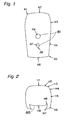
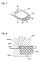
- the radii r of curvature refer to radii of curvature of a top surface of an outer periphery or inner periphery (hole) of an injection molded article in plan view (for example, see radii A1 through A9 of curvature in Fig. 1, radii H1 through H9 of curvature in Fig. 2, radii B1 through B17 of curvature in Fig. 3, and radii F1 through F4 of curvature in Fig. 4 in injection molded articles that can be molded in accordance with the present invention but are difficult to mold in accordance with the prior arts), and the radii r of curvature are expressed in units of mm.
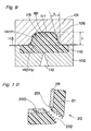
- the radii R of curvature refer to radii of curvature at corners of a top surface of an outer periphery or inner periphery (hole) of an injection molded article in section (see Fig. 5, Fig. 6, Fig. 8, and Fig. 9) and are expressed in units of mm.
- the radii R 2 of curvature refer to radii of curvature at parting corners of an outer periphery or inner periphery (hole) of an injection molded article in section (see Fig. 6 and Fig. 9) and are expressed in units of mm.
- the distance D and the distance H refer to a distance from a top surface of an outer periphery or inner periphery (recessed part) to a reference surface in an injection molded article in section (see Fig. 5, Fig. 6, Fig. 8, and Fig. 9) and are expressed in units of mm.
- the drafts A refer to drafts at parting corners of an outer periphery or inner periphery (recessed part) of an injection molded article in section) (see Fig. 5, Fig. 6, Fig. 8, and Fig. 9) and are expressed in units of degrees (°).
- An object of the present invention is to solve the above issues and to provide injection molds and a method of manufacturing an injection molded article by which the injection molded article is obtained that sustains no ink crack in a transfer layer and no break in a transfer member and that is excellent in designability with a clear contour of a top surface of an outer periphery or inner periphery (recessed part) thereof.
- the present invention is configured as follows.
- an injection molded article which has a transfer layer bonded onto and integrated with a surface thereof and in which a sectional shape of a part of the injection molded article where a radius r of curvature is smallest satisfies R ⁇ D and 0.1 ⁇ rRA/D ⁇ 10, wherein the radius r of curvature is a radius (mm) of curvature of a top surface on an outer periphery or an inner periphery of the injection molded article in plan view, R is a radius (mm) of curvature of the top surface on the outer periphery or the inner periphery of the injection molded article in sectional view, D is a height (mm) from the top surface on the outer periphery or the inner periphery of the injection molded article to a reference surface in sectional view, and A is a draft (°) at a parting corner on the outer periphery or the inner periphery of the injection molded
- an injection molded article which has a transfer layer bonded onto and integrated with a surface thereof and in which a sectional shape of a part of the injection molded article where a radius r of curvature is smallest satisfies R ⁇ D and 0.2 ⁇ rR/D ⁇ 30, wherein the radius r of curvature is a radius (mm) of curvature of a top surface on an outer periphery or an inner periphery of the injection molded article in plan view, R is a radius (mm) of curvature of the top surface on the outer periphery or the inner periphery of the injection molded article in sectional view, and D is a height (mm) from the top surface on the outer periphery or the inner periphery of the injection molded article to a reference surface in sectional view.
- an injection molded article which has a transfer layer bonded onto and integrated with a surface thereof and has a protruding part or a recessed part formed on the surface, and in which a sectional shape of a part of the protruding part or the recessed part where a radius r of curvature is smallest satisfies 0.01 ⁇ rRR 2 A/H ⁇ 1.0, wherein the radius r of curvature is a radius (mm) of curvature of a top surface of the protruding part or the recessed part of the injection molded article in plan view, R is a radius (mm) of curvature of the top surface of the protruding part or the recessed part of the injection molded article in sectional view, R 2 is a radius (mm) of curvature of a bottom of the protruding part or the recessed part of the injection molded article in sectional view, H is a height (mm) from the top surface of the pro
- an injection molded article as defined in the first aspect, wherein at least one of the radii R of curvature, the drafts A, and the distances D of the injection molded article are identical in all parts.
- an injection molded article as defined in the second aspect, wherein at least one of the radii R of curvature and the distances D of the injection molded article are identical in all parts.
- an injection molded article as defined in the third aspect, wherein at least one of the radii R of curvature, the radii R of curvature and the radii R 2 of curvature, the drafts A, and the heights H of the injection molded article are identical in all parts.
- an injection molded article as defined in the first aspect, wherein a sectional shape of a part having a smallest radius r of curvature in a first region (I) of the injection molded article satisfies R ⁇ D and 0.1 ⁇ rRA/D ⁇ 10, and wherein a sectional shape of a part having a smallest radius r of curvature in a second region (II) different from the first region satisfies R ⁇ D and 0.2 ⁇ rR/D ⁇ 30, wherein the radius r of curvature in the second region is a radius (mm) of curvature of a top surface on the outer periphery or the inner periphery of the injection molded article in plan view, R in the second region is a radius of curvature of the top surface on the outer periphery or the inner periphery of the injection molded article in sectional view, and D in the second region is a height (mm) from
- an injection molded article as defined in the first aspect, wherein a sectional shape of a part having a smallest radius r of curvature in a first region (I) of the injection molded article satisfies R ⁇ D and 0.1 ⁇ rRA/D ⁇ 10, and wherein a sectional shape of a part in which a radius r of curvature of a protruding part or a recessed part is smallest in a third region (III) different from the first region satisfies 0.01 ⁇ rRR 2 A/H ⁇ 1.0, wherein the radius r of curvature in the third region is a radius (mm) of curvature of a top surface on the protruding part or the recessed part of the injection molded article in plan view, R in the third region is a radius (mm) of curvature of the top surface of the protruding part or the recessed part of the injection molded article in sectional view, R 2
- an injection molded article as defined in the second aspect, wherein a sectional shape of a part having a smallest radius r of curvature in a second region (II) of the injection molded article satisfies R ⁇ D and 0.2 ⁇ rR/D ⁇ 30, and wherein a sectional shape of a part in which a radius r of curvature of the protruding part or the recessed part is smallest in a third region (III) different from the second region satisfies 0.01 ⁇ rRR 2 A/H ⁇ 1.0, wherein the radius r of curvature in the third region is a radius (mm) of curvature of a top surface on the protruding part or the recessed part of the injection molded article in plan view, R in the third region is a radius (mm) of curvature of the top surface of the protruding part or the recessed part of the injection molded article in sectional view, R 2
- an injection molded article as defined in the first aspect, wherein a sectional shape of a part having a smallest radius r of curvature in a first region (I) of the injection molded article satisfies R ⁇ D and 0.1 ⁇ rRA/D ⁇ 10, wherein a sectional shape of a part having a smallest radius r of curvature in a second region (II) different from the first region satisfies R ⁇ D and 0.2 ⁇ rR/D ⁇ 30, wherein the radius r of curvature in the second region is a radius (mm) of curvature of a top surface on the outer periphery or the inner periphery of the injection molded article in plan view, R in the second region is a radius of curvature of the top surface on the outer periphery or the inner periphery of the injection molded article in sectional view, and D in the second region is a height (mm) from
- a method of manufacturing an injection molded article comprising of:
- a method of manufacturing an injection molded article comprising of:
- a method of manufacturing an injection molded article comprising of:
- injection molds comprising:
- injection molds comprising:
- injection molds comprising:
- Fig. 11 is a sectional view, partially broken away, showing an example of an injection molded article and injection molds of a first embodiment of the present invention
- Fig. 12 is a sectional view showing an example of an injection molded article and injection molds of a second embodiment of the present invention
- Fig. 13 is a sectional view showing an example of an injection molded article and injection molds of a third embodiment of the present invention
- Fig. 14 is a sectional view showing an example of an injection molded article and injection molds of the third embodiment of the present invention
- Fig. 15 is a sectional view showing an example of an injection molded article and injection molds of a fourth embodiment of the present invention.
- the injection molded article of the first embodiment of the present invention is an injection molded article 15a having a transfer layer of a transfer member 13a bonded onto and integrated with a surface thereof, as shown in Fig. 11, the injection molded article 15a satisfying specific conditions below.
- Figs. 1 through 4 are plan views showing an upper cover of a portable telephone that is an example of the injection molded article of the first embodiment of the present invention
- Fig. 2 is a plan view showing an upper cover of a portable telephone that is another example of the injection molded article of the first embodiment of the present invention
- FIG. 3 is a plan view showing a lower cover of a portable telephone that is still another example of the injection molded article of the first embodiment of the present invention
- Fig. 4 is a plan view showing a lower cover of a portable telephone that is still another example of the injection molded article of the first embodiment of the present invention.
- Reference numerals 81 denote holes and numeral 85 denotes a cutout.
- a radius (mm) of curvature at a corner 41a of a top surface 11a of an outer periphery or inner periphery of the injection molded article 15a in plan view specifically, see the radii A1 through A9 of curvature in Fig. 1, the radii H1 through H9 of curvature in Fig. 2, the radii B1 through B17 of curvature in Fig. 3, and the radii F1 through F4 of curvature in Fig.
- r a radius (mm) of curvature at the corner 41a of the top surface 11a of the outer periphery or inner periphery of the injection molded article 15a in section
- R a radius (mm) of curvature at the corner 41a of the top surface 11a of the outer periphery or inner periphery of the injection molded article 15a in section
- D a distance (mm) from the.top surface 11a of the outer periphery or inner periphery to a reference surface 10a in the injection molded article 15a in section
- A a draft (°) at a parting corner 42a of the outer periphery or inner periphery of the injection molded article 15a in section
- R ⁇ D a straight side surface 6a exists in vicinity of bottom of the outer periphery of the injection molded article 15a, and the draft A is equivalent to an angle between the straight side surface 6a and a plane orthogonal to the bottom 19a.
- an in-depth experiment has proven that the radius r of curvature, the radius R of curvature, and the draft A are inversely proportional to one another and that those are directly proportional to a square of the distance D.
- an injection molded article that sustains no ink crack in a transfer layer and no break in a transfer member and that is excellent in designability with a clear contour of a top surface of an outer periphery or inner periphery (recessed part) thereof is obtained by selection of a part of the injection molded article 15a where the radius r of curvature is the smallest (e.g., parts with the radius A5 of curvature in Fig. 1, the radius H7 of curvature in Fig. 2, the radius B7 of curvature in Fig. 3, and the radius F1 of curvature in Fig. 4) and by satisfaction of relational expressions R ⁇ D and 0.1 ⁇ rRA/D ⁇ 10 in a section of the part.
- the radius R of curvature is required to be as large as possible or the draft A is required to be large so that a shape of the section may satisfy the above relational expressions.
- the radius R of curvature coincides with the distance D (in an injection molded article 15b of the second embodiment in Fig. 12) or on condition that the radius R of curvature is larger than the distance D (i.e., R ⁇ D)
- the section becomes having an arc shape without the straight part and makes it impossible to define the draft A and to apply the relational expressions of the first embodiment.
- an injection molded article that sustains no ink crack in a transfer layer and no break in a transfer member and that is excellent in designability with a clear contour of a top surface of an outer periphery or inner periphery (recessed part) thereof is obtained by exclusion of the draft A from the relational expressions in accordance with the second embodiment, that is, by selection of a part of the injection molded article where the radius r of curvature is the smallest and by satisfaction of a relational expression 0.2 ⁇ rR/D ⁇ 30 in a section of the part.
- character "r” denotes a radius (mm) of curvature at a corner 41b of a top surface 11b of an outer periphery or inner periphery of the injection molded article 15b in plan view (specifically, corresponding to the radii A1 through A9 of curvature in Fig. 1, the radii H1 through H9 of curvature in Fig. 2, the radii B1 through B17 of curvature in Fig. 3, and the radii F1 through F4 of curvature in Fig.
- character "R” denotes a radius (mm) of curvature at the corner 41b of the top surface 11b of the outer periphery or inner periphery of the injection molded article 15b in section
- character "D” denotes a distance (mm) from the top surface 11b of the outer periphery or inner periphery to a reference surface 10b in the injection molded article 15b in section.
- the inner periphery of the injection molded article is not pierced but only recessed, that is, in which a protruding part 81c such as a protruding character is formed on a top surface 11c of an injection molded article 15c (see Figs. 13 and 19).
- Reference character 13c denotes a transfer member
- character 1c denotes a movable mold
- character 41c denotes a top surface corner (having a radius R of curvature)
- character 6c denotes a straight part
- character 10c denotes a reference surface
- character 2c denotes a fixed mold
- character 12c denotes an injection port
- character 42c denotes a parting corner (having a radius R 2 of curvature).
- a recessed part 82d such as groove and recessed character is formed on a top surface 11d of an injection molded article 15d (see Figs. 14 and 20).
- Reference character 13d denotes a transfer member
- character 1d denotes a movable mold
- character 41d denotes a top surface corner (having a radius R of curvature)
- character 6d denotes a straight part
- character 10d denotes a reference surface
- character 2d denotes a fixed mold
- character 12d denotes an injection port
- character 42d denotes a parting corner (having a radius R 2 of curvature).
- account has to be taken of the radius R 2 of curvature of the parting corner 42c, 42d in the protruding part 81c or the recessed part 82d and of a distance H from the top surface 11c, 11d of the protruding part 81c or the recessed part 82d to the reference surface 10c, 10d in the injection molded article 15c, 15d in section, and relational expressions thereof are therefore different from those of the first embodiment and the second embodiment.
- the injection molded article that sustains no ink crack in a transfer layer and no break in the transfer member and that is excellent in designability with a clear contour of the top surface of an outer periphery or inner periphery (recessed part) thereof is obtained by selection of a part of the protruding part 81c or the recessed part 82d of the injection molded article 15c, 15d where the radius r of curvature is the smallest and by satisfaction of a relational expression 0.01 ⁇ rRR 2 A/H ⁇ 1.0 in a section shape of the part.
- Reference character "r” denotes the radius (mm) of curvature at the corner 41c, 41d of the top surface 11c, 11d of the outer periphery or inner periphery of the injection molded article 15c, 15d in plan view (specifically, corresponding to the radii A1 through A9 of curvature in Fig. 1, the radii H1 through H9 of curvature in Fig. 2, the radii B1 through B17 of curvature in Fig. 3, and the radii F1 through F4 of curvature in Fig.
- character "R” denotes the radius (mm) of curvature at the corner 41c, 41d of the top surface 11c, 11d of the outer periphery or inner periphery of the injection molded article 15c, 15d in section
- character “D” denotes a distance (mm) from the top surface 11c, 11d of the outer periphery or inner periphery to the reference surface 10c, 10d in the injection molded article 15c, 15d in section
- character "A” denotes a draft (°) at the parting corner 42c, 42d of the outer periphery or inner periphery of the injection molded article 15c, 15d in section
- character "R 2 " denotes the radius (mm) of curvature at a bottom, i.e., the parting corner 42c, 42d of the protruding part 81c or the recessed part 82d of the injection molded article 15c, 15d in section
- character "H” denotes a height (mm)
- the relational expressions of the first to third embodiments apply only to the part of the injection molded article 15a, 15b, 15c, 15d where the radius r of curvature is the smallest (corresponding to the parts with the radius A5 of curvature in Fig. 1, the radius H7 of curvature in Fig. 2, the radius B7 of curvature in Fig. 3, and the radius F1 of curvature in Fig. 4, for example), and the relational expressions do not have to be satisfied in parts with larger radii r of curvature and in straight parts (the radius A4 of curvature in Fig. 1 and the radii B13 and B15 of curvature in Fig. 4).
- the radii R of curvature, the radii R 2 of curvature, and the drafts A of the parts having larger radii r of curvature and of the straight parts may be made smaller than the radius R of curvature, the radius R 2 of curvature, and the draft A of the part having the smallest radius r of curvature, or the distances D or the distances H in the parts having larger radii r of curvature and in the straight parts may be made larger than the distance D or the distance H in the part having the smallest radius r of curvature, so that the relational expressions may be satisfied.
- At least one of the radii R of curvature, the radii R 2 of curvature, the drafts A, the distances D, and the distances H in the parts having larger radii r of curvature and in the straight parts may be equal to at least one of the radius R of curvature, the radius R 2 of curvature, the draft A, the distance D, and the distance H in the part having the smallest radius r of curvature.
- the radius R 2 of curvature, the draft A, the distance D, and the distance H among parts of an injection molded article causes enormous trouble in design and manufacture of the injection mold, and it is efficient and preferable to make at least one of the radii R of curvature, the radii R 2 of curvature, the drafts A, the distance D, and the distance H identical in all the parts of the injection molded article unless special circumstances exist.
- an injection molded article 15e is divided into a first region I to which the first embodiment is applied, a second region II to which the second embodiment is applied, and a third region III to which the third embodiment is applied, and all of the radius R of curvature, the radius R 2 of curvature, the draft A, the distance D, and the distance H are identical in all the parts or all the regions of the injection molded article 15e.
- Such a configuration can significantly reduce the trouble in design and manufacture of injection molds in comparison with a configuration having variation in the radius R of curvature, the radius R 2 of curvature, the draft A, the distance D, and the distance H among parts of an injection molded article.
- the fourth embodiment in which a plurality of parts according to the first to third embodiments exist in one injection molded article 15e requires the relational expressions to be satisfied in each of the parts or regions I, II, and III according to the first to third embodiments (see Fig. 15).
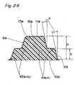
- Reference character 13e denotes a transfer member
- character 81e denotes a protruding part
- character 11e denotes a top surface
- character 1e denotes a movable mold
- character 41e denotes top surface corners (having radii R of curvature)
- character 6e denotes a straight part
- character 10e denotes a reference surface
- character 2e denotes a fixed mold
- character 12e denotes an injection port
- character 42e denotes parting corners (having radii R 2 of curvature).
- the radii r of curvature, the radii R of curvature, the distances D, the drafts A, and the distances H of the injection molded articles 15a, 15b, 15c, 15d, and 15e in accordance with the first to fourth embodiments of the present invention are determined by the shape of the radii r of curvature, the radii R of curvature, the distances D, the drafts A, and. the distances H of the movable molds 1a, 1b, 1c, 1d, and 1e, respectively.
- the injection molds for producing the injection molded articles 15a, 15b, 15c, 15d, and 15e in accordance with the first to fourth embodiments of the present invention will be described below.
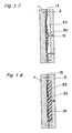
- the injection molds in accordance with the first to fourth embodiments of the present invention are configured at least by the movable mold 1a, 1b, 1c, 1d, 1e that is brought into contact with transfer member 13a, 13b, 13c, 13d, 13e and the fixed mold 2a, 2b, 2c, 2d, 2e that has the molding resin injection port 12a, 12b, 12c, 12d, 12e (see Fig. 16).
- the movable molds 1a, 1b, 1c, 1d, and 1e are shown as a movable mold 1
- the fixed molds 2a, 2b, 2c, 2d, and 2e are shown as a fixed mold 2
- the molding resin injection ports 12a, 12b, 12c, 12d, and 12e are shown as a molding resin injection port 12
- the transfer members 13a, 13b, 13c, 13d, and 13e are shown as a transfer member 13.
- Reference character 1A denotes a cavity on side of the movable mold 1
- character 2A denotes a cavity on side of the fixed mold 2
- numeral 30 denotes molding resin
- numeral 33 denotes a molding space.
- Table 1 below shows results of tests on the radius A5 of curvature and the radius A6 of curvature in Fig. 1
- Table 2 shows those on the radius H7 of curvature in Fig. 2
- Table 3 shows those on the radius B7 of curvature in Fig. 3
- Table 4 shows those on the radius F1 of curvature and the radius F4 of curvature in Fig. 4.
- the radius A6 of curvature was selected because D > R was satisfied and because the part had the smallest radius r of curvature in the parts where measurement was carried out.
- the radius A5 of curvature was selected because D ⁇ R was satisfied and because the part had the smallest value of r in the parts where the measurement was carried out.
- the radius H7 of curvature was selected because the part had the smallest radius r of curvature in the parts where the measurement was carried out.
- the radius B7 of curvature was selected because the part had the smallest radius r of curvature in the parts where the measurement was carried out.
- the radius F1 of curvature was selected because D > R was satisfied and because the part had the smallest radius r of curvature in the parts where the measurement was carried out.
- the radius F4 of curvature was selected because D ⁇ R was satisfied and because the part had the smallest value of r in the parts where the measurement was carried out.
- the draft A is preferably in a range of from 0.3° to 45°. On condition that the draft is larger than 45°, too large reduction in quantity of flow of molding resin hinders sufficient transmission of a pressure required for the transfer, especially in the parting corners, and thus causes poor adhesion between the transfer layer 29 and the molding resin.
- the draft A is more preferably in a range of from 0.3° to 10° in order to ensure the sufficient transmission of the pressure required for the transfer and prevention of ink cracks in the transfer layer 29 and breaks in the transfer member 13.
- the draft A is preferably in a range of from 0.3° to 5° in order that the obtained injection molded article 15 may have such a shape that side surfaces thereof are concealed from plan view.
- the drafts A smaller than 0.3° make it difficult to remove the injection molded article 15 from the movable mold 1.
- the distance D is preferably in a range of from 0.15 to 8.0 mm.
- the distances D smaller than 0.15 mm make it difficult to form the radius R of curvature and the draft A.
- both the draft A and the radius R of curvature are required to be made large in order to facilitate removal of the injection molded article 15 from the movable mold 1 and, consequently, the transfer member cannot be drawn fully and may be broken.
- a large drop end with the distance D of several millimeters or larger is formed, and both the distance D and the radius R of curvature of such an injection molded article are required to be made large in order to satisfy the relational expressions.
- drop end refers to a part that has a plurality of surfaces on which the movable mold and the fixed mold are in contact with each other, as shown in Fig. 12, that is an end of an injection molded article satisfying a condition of D ⁇ R, and that configures a reference surface.
- the distance D is more preferably in a range of from 0.3 to 2.0 mm.
- the distances D larger than 2.0 mm tend to make it difficult to prevent ink cracks in the transfer layer 29 and breaks in the transfer member 13, and thus require trial and error for countermeasures against that on occasion of molding.
- the distances D smaller than 0.3 mm decrease a quantity of expansion of the transfer member 13, deteriorate tearing of the transfer layer 29, and thus increase an amount of so-called foil fin that is excess transfer layer 29 adhering to the injection molded article 15. With increase in the amount of foil fin, the fin tends to be dispersed into the molds and may adhere onto subsequent injection molded articles 15.
- the radius R of curvature is preferably in a range of from 0.05 to 2.0 mm when the radius R is smaller than the distance D (R ⁇ D).
- the radius R of curvature is smaller than 0.05 mm, the substrate sheet 21 is stretched too much by resin pressure of molding resin in curved parts in section, so that ink cracks may be caused in the transfer layer 29 and so that the transfer member 13 is prone to be broken.
- the radius R of curvature exceeds 2.0 mm, the straight part 6 is often eliminated and the relational expressions of the first embodiment and the third embodiment do not hold.
- the second embodiment i.e., when R ⁇ D holds), there is no upper limit to the radius R of curvature.
- 0.05 (mm) ⁇ r holds.
- the radii r of curvature smaller than 0.05 (mm) make it difficult to prevent ink cracks in the transfer layer 29 and breaks in the transfer member 13 even if other parameters are manipulated.
- Upper limit of the radius is infinity. That is because there are such straight parts as B13, B15, and B17 in Table 3.
- the injection molds in accordance with the third embodiment of the present invention are injection molds for forming the protruding part 81c or the recessed part 81d such as character, figure, symbol, and pattern on a surface of the injection molded article 15, and the injection molds have the protruding part 81c or the recessed part 81d on the top surface 11c, 11d of the movable mold 1c, 1d.
- the distance H is in a range of from 0.1 to 1.0 mm
- the radius R of curvature is in a range of from 0.1 to 0.4 mm
- the radius R 2 of curvature is in a range of from 0.1 to 0.4 mm
- the draft A is in a range from 2° to 30°.
- the distance H refers to a distance from the top surface 11c, 11d to the reference surface 10c, 10d (see Fig. 13 and Fig. 14).
- the distance H is larger than the distance D (see Fig. 15).
- the distance H is smaller than the distance D (see Fig. 14).
- the distances H smaller than 0.1 mm make it difficult to form the radius R of curvature, the radius R 2 of curvature, and the draft A, tend to make difference in level indistinctive, and make it difficult to recognize a state in which characters rise from the surface.
- the distances H larger than 1.0 mm make it difficult to remove the injection molded article 15 from the movable mold 1. Besides, degrees of bending and drawing of the transfer member are increased, ink cracks may be caused in the transfer layer, and wrinkles and breaks are prone to be caused in the transfer member (see Fig. 10).
- the substrate sheet 21 is stretched too much by resin pressure of molding resin in a part having the curvature, so that ink cracks may be caused in the transfer layer 29 and so that the transfer member 13 is prone to be broken.
- the radius R of curvature is larger than 0.4 mm, too much gentleness in the corner makes it difficult to recognize a state in which characters rise from the surface.
- the substrate sheet 21 is stretched too much by resin pressure of molding resin in a part having the curvature, so that ink cracks may be caused in the transfer layer 29 and so that the transfer member 13 is prone to be broken.
- the radius R 2 of curvature is larger than 0.4 mm, too much gentleness in the corner makes it difficult to recognize a state in which characters rise from the surface.
- 0.05 (mm) ⁇ r holds.
- the radii r of curvature smaller than 0.05 (mm) make it difficult to prevent ink cracks in the transfer layer 29 and breaks in the transfer member 13 even if other parameters are manipulated.
- Upper limit of the radius is infinity. That is because there are such straight parts as B13, B15, and B17 in Table 3.
- the most preferable combination of those elements is a combination of the distance H of 0.4 mm, the radius R of curvature of 0.15 mm, the radius R 2 of curvature of 0.15 mm, and the draft A of 15°.
- the injection molds for molding the injection molded article 15 are configured so as to have the movable mold 1 with the cavity 1A and the fixed mold 2 with the cavity 2A.
- the cavity 1A or 2A or the cavities 1A and 2A of at least either one or both of the movable mold 1 and the fixed mold 2 have curved parts 1a-1 and 1a-2 which are molded so that a sectional shape of a part of the injection molded article having the smallest radius r of curvature satisfies the expressions R ⁇ D and 0.1 ⁇ rRA/D ⁇ 10.
- the second embodiment as shown in Figs.
- the cavity 1A or 2A or the cavities 1A and 2A of at least either one or both of the movable mold 1 and the fixed mold 2 similarly have curved parts 1b-1 and 1b-2 which are molded so that a sectional shape of a part of the injection molded article having the smallest radius r of curvature satisfies the expressions R ⁇ D and 0.2 ⁇ rR/D ⁇ 30.
- the third embodiment as shown in Figs.
- the cavity 1A or 2A or the cavities 1A and 2A of at least either one or both of the movable mold 1 and the fixed mold 2 have curved parts 1c-1, 1c-2, 1d-1, 1d-2 which are molded so that a sectional shape of a part of the injection molded article having the smallest radius r of curvature satisfies the expression 0.01 ⁇ rRR 2 A/H ⁇ 1.0.
- parts for molding the first to third regions I, II, and III to which the corresponding curved parts of the first to third embodiments appropriately correspond are provided with the corresponding curved parts.
- the transfer member 13 having the transfer layer 29 on the substrate sheet 21 is placed between the movable mold 1 having the cavity 1A and the fixed mold 2 having the cavity 2A (Fig. 16).
- the transfer member 13 is placed so as to be inserted and held in appropriate position between the cavity 1A of the movable mold 1 and the cavity 2A of the fixed mold 2.
- a plurality of sheets of transfer member 13 may be fed and placed one by one or only required parts of a long film of transfer member 13 may intermittently and continually be fed and placed as they are without being cut.
- positioning with use of a feeder having a positioning mechanism is preferably carried out so that the transfer member 13 and the injection molds may be in register.
- the transfer member 13 is intermittently fed, it is advantageous to fix the transfer member 13 by the movable mold 1 and the fixed mold 2 after detection of positions of the transfer member 13 by a sensor, because the transfer member 13 can thereby be fixed in the same position at all times and because the transfer member 13 is thus prevented from being out of position.
- the transfer member 13 is preformed and deformed along an inside surface of the cavity 1A of the movable mold 1 (Fig. 17).
- the sheet On condition that the plurality of sheets of transfer member 13 are fed one by one, the sheet may be deformed so as to fit in the cavity 1A of the movable mold 1 before being fed into the injection molds, then may be fed into the injection molds, and may be placed so as to fit in the cavity 1A of the movable mold 1.
- the preformation is preferably carried out with deformation of the transfer member 13 into a three-dimensional shape by vacuum forming, press forming, or the like.
- the molding space 33 is formed by closure of the molds, molding resin 30 is injected into the molding space 33, an injection molded article 15 having a sectional shape with desired radii of curvature is formed with use of the curved parts and, at the same time, the transfer layer 29 of the transfer member 13 is bonded onto and integrated with a surface of the injection molded article 15 (Fig. 18).
- the movable mold 1 is moved relative to the fixed mold 2, and the injection molded article 15 is taken out.
- the transfer layer 29 has been bonded onto and integrated with the solidified molding resin 30 by an adhesive layer 24, in the parts having the sectional shape with the desired radii of curvature in the same manner as in other parts.
- the injection molded articles 15a, 15b, 15c, 15d, and 15e of the first through fourth embodiments are shown in Figs. 22, 23, 24, 25, and 26, respectively.
- the molding resin 30 may be used acrylic resin, polystyrene resin, styrene-acrylonitrile resin, polycarbonate resin, polypropylene resin, polyethylene resin, polylactic acid resin, nylon resin, polyurethane resin, polyester resin, polymer alloy of those, or the like.
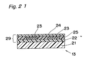
- a release layer 22, a pattern layer 23, a function layer 25, and the adhesive layer 24 are laminated on the substrate sheet 21 in order, and a laminate of the release layer 22, the pattern layer 23, the function layer 25, and the adhesive layer 24 forms the transfer layer 29 (see Fig. 21).
- materials for the substrate sheet 21 are resin sheets of acrylic resin, polyester resin, and the like.
- the pattern layer 23 As material of the pattern layer 23, there can be named acrylic resin, nitrocellulose resin, urethane resin, chlorinated rubber resin, vinyl chloride vinyl acetate copolymer resin, polyamide resin, polyester resin, epoxy resin, and the like; however, the material is not particularly limited thereto.
- a metal film layer of aluminum, chromium, copper, nickel, indium, tin, silicon oxide, or the like may be provided by vacuum deposition method, plating method, or the like. In this case, the metal film layer may cover the whole surface or may be patterned.
- a film thickness of the pattern layer 23 is preferably in a range of from 0.5 ⁇ m to 50 ⁇ m.
- a film thickness of the metal film layer is preferably in a range of from 50 ⁇ to 1200 ⁇ . That is because sufficient metallic luster cannot be obtained with the film thickness of the metal film layer smaller than 50 ⁇ and because cracks are prone to occur with the film thickness larger than 1200 ⁇ .
- methods for providing the pattern layer 23 on the whole surface or on a pattern are general printing methods such as gravure, screen process printing, and offset printing; tampon printing; painting; various coating methods; metal film forming methods such as vapor deposition, ion plating, and sputter technique; and the like.
- Preferably used as material of the adhesive layer 24 is acrylic resin, nitrocellulose resin, urethane resin, chlorinated rubber resin, vinyl chloride vinyl acetate copolymer resin, polyamide resin, polyester resin, epoxy resin, polycarbonate resin, olefinic resin, acrylonitrile-butadien-styrene resin, or the like.
- a thickness of the adhesive layer 24 is preferably in a range of from 0.5 ⁇ m to 50 ⁇ m. That is because sufficient adhesiveness cannot be obtained with the film thickness smaller than 0.5 ⁇ m and because drying after printing is difficult to perform with the film thickness larger than 50 ⁇ m.
- a method of forming the adhesive layer 24 may be any of general printing methods such as gravure, offset printing, and screen process printing, painting, dipping, reverse coater, and the like.
- Preferably used as material of the release layer 22 is acrylic resin, acetate resin, urethane resin, chlorinated rubber resin, vinyl chloride vinyl acetate copolymer resin, polyamide resin, polyester resin, epoxy resin, polycarbonate resin, olefinic resin, cyanoacrylate resin, or the like.
- a thickness of the release layer 22 is preferably in a range of from 0.5 ⁇ m to 50 ⁇ m. That is because sufficient adhesiveness cannot be obtained with the film thickness smaller than 0.5 ⁇ m and because drying after printing is difficult to perform with the film thickness larger than 50 ⁇ m.
- the function layer 25 provided between the layers has functions of improving adherence between the layers, improving resistance against corrosion of the layers, and the like.
- material of the function layer 25 is thermosetting acrylic resin, thermosetting urethane resin, vinyl chloride vinyl acetate copolymer resin, polyamide resin, polyester resin, epoxy resin, or the like.
- a thickness of the function layer 25 is preferably in a range of from 0.5 ⁇ m to 50 ⁇ m. That is because the functions of improving adherence between the layers, improving resistance against corrosion of the layers, and the like cannot be achieved with the film thickness smaller than 0.5 ⁇ m and because drying after printing is difficult to perform with the film thickness larger than 50 ⁇ m.
- a method of forming the function layer 25 may be any of general printing methods such as gravure, offset printing, and screen process printing, painting, dipping, reverse coater, and the like.
- a transfer layer is bonded onto and integrated with a surface thereof, and it is characterized that a sectional shape of a part of the injection molded article where the radius r of curvature is the smallest satisfies conditions of R ⁇ D and 0.1 ⁇ rRA/D ⁇ 10, conditions of R ⁇ D and 0.2 ⁇ rR/D ⁇ 30, or a condition of 0.01 ⁇ rRR 2 A/H ⁇ 1.0. Provided that such condition(s) are satisfied, it is not difficult to remove the injection molded article from the injection molds even in the part where the radius r of curvature is the smallest, and molding resin is not forced into corners having steep angles.
- the injection molded article that prevents occurrence of ink cracks in the transfer layer and breaks in the transfer member (breaks in the transfer layer and breaks in the substrate sheet) and that is excellent in designability with a clear contour of a top surface of an outer periphery or inner periphery (recessed part) thereof.
- any of the radii R of curvature, the radii R of curvature and the radii R 2 of curvature, the drafts A, and the distances D are identical in all the parts thereof.
- any of the radii R of curvature, the radii R of curvature and the radii R 2 of curvature, the drafts A, and the distances D are identical in all the parts thereof.
- the transfer member having the transfer layer on the substrate sheet is placed between the movable mold at least in contact with the transfer member and the fixed mold having the molding resin injection port, molding resin is injected from the molding resin injection port into the molding space formed by closure of the molds, and thus the transfer layer is bonded onto and integrated with the surface of the injection molded article at the same time that the injection molded article is formed.
- the injection molds of the present invention are injection molds that are used in the method of manufacturing the injection molded article.
- an effect is achieved in that there is obtained the injection molded article which prevents occurrence of ink cracks in the transfer layer and breaks in the transfer member and which is excellent in designability with a clear contour of the top surface of the outer periphery or inner periphery (recessed part) thereof.
Landscapes
- Engineering & Computer Science (AREA)
- Manufacturing & Machinery (AREA)
- Mechanical Engineering (AREA)
- Injection Moulding Of Plastics Or The Like (AREA)
- Moulds For Moulding Plastics Or The Like (AREA)
Abstract
An injection molded article (15) which has a
transfer layer (29) bonded onto and integrated with a
surface thereof and in which a sectional shape of a part of
a corner of a top surface of the injection molded article
where a radius r of curvature is the smallest satisfies
conditions of R < D and 0.1 ≤ rRA/D ≤ 10, or R ≥ D and 0.2
≤ rR/D ≤ 30, or 0.01 ≤ rRR2A/H ≤ 1.0, wherein R is a radius
of curvature of the corner of the top surface, D is a
distance between the top surface and a reference surface, A
is a draft at a parting corner, R2 is a radius of curvature
at the parting corner, and H is a distance between a top
surface of a recessed part and the reference surface.
Description
The present invention relates to an injection
molded article having a transfer layer bonded on and
integrated with surfaces thereof, such as upper and lower
covers of portable telephone, surface component and outer
periphery component of electronic toy, input panel of rice
cooker, interior and exterior panels of motor car, and
outer frame of pachinko machine, a method of manufacturing
the same, and injection molds.
As a method of decorating not only a top surface
but side surfaces of an injection molded article,
conventionally, there has been used a method in which
transfer layers are bonded on and integrated with the
surfaces of the injection molded article simultaneously
with injection molding.
For a shape of an outer peripheral or inner
peripheral surface of an injection molded article, in most
cases, different parts often have different radii r of
curvature (radii of curvature at corners of an outer
peripheral or inner peripheral top surface of the injection
molded article in plan view)(for example, in such injection
molded articles as shown in Figs. 1, 2, 3, 4, and 7 which
can be molded in accordance with the present invention but
are difficult to mold in accordance with the prior arts).
Accordingly, the bonding and integration of transfer layers
with surfaces of such an injection molded article cause
following issues in a part where the radius r of curvature
is the smallest.
Herein, the radii r of curvature refer to radii
of curvature of a top surface of an outer periphery or
inner periphery (hole) of an injection molded article in
plan view (for example, see radii A1 through A9 of
curvature in Fig. 1, radii H1 through H9 of curvature in
Fig. 2, radii B1 through B17 of curvature in Fig. 3, and
radii F1 through F4 of curvature in Fig. 4 in injection
molded articles that can be molded in accordance with the
present invention but are difficult to mold in accordance
with the prior arts), and the radii r of curvature are
expressed in units of mm. The radii R of curvature refer
to radii of curvature at corners of a top surface of an
outer periphery or inner periphery (hole) of an injection
molded article in section (see Fig. 5, Fig. 6, Fig. 8, and
Fig. 9) and are expressed in units of mm. The radii R2 of
curvature refer to radii of curvature at parting corners of
an outer periphery or inner periphery (hole) of an
injection molded article in section (see Fig. 6 and Fig. 9)
and are expressed in units of mm. The distance D and the
distance H refer to a distance from a top surface of an
outer periphery or inner periphery (recessed part) to a
reference surface in an injection molded article in section
(see Fig. 5, Fig. 6, Fig. 8, and Fig. 9) and are expressed
in units of mm. The drafts A refer to drafts at parting
corners of an outer periphery or inner periphery (recessed
part) of an injection molded article in section) (see Fig. 5,
Fig. 6, Fig. 8, and Fig. 9) and are expressed in units of
degrees (°).
An object of the present invention is to solve
the above issues and to provide injection molds and a
method of manufacturing an injection molded article by
which the injection molded article is obtained that
sustains no ink crack in a transfer layer and no break in a
transfer member and that is excellent in designability with
a clear contour of a top surface of an outer periphery or
inner periphery (recessed part) thereof.
In order to achieve the object, the present
invention is configured as follows.
According to a first aspect of the present
invention, there is provided an injection molded article
which has a transfer layer bonded onto and integrated with
a surface thereof and
in which a sectional shape of a part of the injection molded article where a radius r of curvature is smallest satisfies R < D and 0.1 ≤ rRA/D ≤ 10,
wherein the radius r of curvature is a radius (mm) of curvature of a top surface on an outer periphery or an inner periphery of the injection molded article in plan view, R is a radius (mm) of curvature of the top surface on the outer periphery or the inner periphery of the injection molded article in sectional view, D is a height (mm) from the top surface on the outer periphery or the inner periphery of the injection molded article to a reference surface in sectional view, and A is a draft (°) at a parting corner on the outer periphery or the inner periphery of the injection molded article in sectional view.
in which a sectional shape of a part of the injection molded article where a radius r of curvature is smallest satisfies R < D and 0.1 ≤ rRA/D ≤ 10,
wherein the radius r of curvature is a radius (mm) of curvature of a top surface on an outer periphery or an inner periphery of the injection molded article in plan view, R is a radius (mm) of curvature of the top surface on the outer periphery or the inner periphery of the injection molded article in sectional view, D is a height (mm) from the top surface on the outer periphery or the inner periphery of the injection molded article to a reference surface in sectional view, and A is a draft (°) at a parting corner on the outer periphery or the inner periphery of the injection molded article in sectional view.
According to a second aspect of the present
invention, there is provided an injection molded article
which has a transfer layer bonded onto and integrated with
a surface thereof and
in which a sectional shape of a part of the injection molded article where a radius r of curvature is smallest satisfies R ≥ D and 0.2 ≤ rR/D ≤ 30,
wherein the radius r of curvature is a radius (mm) of curvature of a top surface on an outer periphery or an inner periphery of the injection molded article in plan view, R is a radius (mm) of curvature of the top surface on the outer periphery or the inner periphery of the injection molded article in sectional view, and D is a height (mm) from the top surface on the outer periphery or the inner periphery of the injection molded article to a reference surface in sectional view.
in which a sectional shape of a part of the injection molded article where a radius r of curvature is smallest satisfies R ≥ D and 0.2 ≤ rR/D ≤ 30,
wherein the radius r of curvature is a radius (mm) of curvature of a top surface on an outer periphery or an inner periphery of the injection molded article in plan view, R is a radius (mm) of curvature of the top surface on the outer periphery or the inner periphery of the injection molded article in sectional view, and D is a height (mm) from the top surface on the outer periphery or the inner periphery of the injection molded article to a reference surface in sectional view.
According to a third aspect of the present
invention, there is provided an injection molded article
which has a transfer layer bonded onto and integrated with
a surface thereof and has a protruding part or a recessed
part formed on the surface, and
in which a sectional shape of a part of the protruding part or the recessed part where a radius r of curvature is smallest satisfies 0.01 ≤ rRR2A/H ≤ 1.0,
wherein the radius r of curvature is a radius (mm) of curvature of a top surface of the protruding part or the recessed part of the injection molded article in plan view, R is a radius (mm) of curvature of the top surface of the protruding part or the recessed part of the injection molded article in sectional view, R2 is a radius (mm) of curvature of a bottom of the protruding part or the recessed part of the injection molded article in sectional view, H is a height (mm) from the top surface of the protruding part or the recessed part of the injection molded article to a reference surface in sectional view, and A is a draft (°) at a top surface corner of the protruding part or the recessed part of the injection molded article in sectional view.
in which a sectional shape of a part of the protruding part or the recessed part where a radius r of curvature is smallest satisfies 0.01 ≤ rRR2A/H ≤ 1.0,
wherein the radius r of curvature is a radius (mm) of curvature of a top surface of the protruding part or the recessed part of the injection molded article in plan view, R is a radius (mm) of curvature of the top surface of the protruding part or the recessed part of the injection molded article in sectional view, R2 is a radius (mm) of curvature of a bottom of the protruding part or the recessed part of the injection molded article in sectional view, H is a height (mm) from the top surface of the protruding part or the recessed part of the injection molded article to a reference surface in sectional view, and A is a draft (°) at a top surface corner of the protruding part or the recessed part of the injection molded article in sectional view.
According to a fourth aspect of the present
invention, there is provided an injection molded article as
defined in the first aspect, wherein at least one of the
radii R of curvature, the drafts A, and the distances D of
the injection molded article are identical in all parts.
According to a fifth aspect of the present
invention, there is provided an injection molded article as
defined in the second aspect, wherein at least one of the
radii R of curvature and the distances D of the injection
molded article are identical in all parts.
According to a sixth aspect of the present
invention, there is provided an injection molded article as
defined in the third aspect, wherein at least one of the
radii R of curvature, the radii R of curvature and the
radii R2 of curvature, the drafts A, and the heights H of
the injection molded article are identical in all parts.
According to a seventh aspect of the present
invention, there is provided an injection molded article as
defined in the first aspect, wherein a sectional shape of a
part having a smallest radius r of curvature in a first
region (I) of the injection molded article satisfies R < D
and 0.1 ≤ rRA/D ≤ 10, and wherein a sectional shape of a
part having a smallest radius r of curvature in a second
region (II) different from the first region satisfies R ≥ D
and 0.2 ≤ rR/D ≤ 30, wherein the radius r of curvature in
the second region is a radius (mm) of curvature of a top
surface on the outer periphery or the inner periphery of
the injection molded article in plan view, R in the second
region is a radius of curvature of the top surface on the
outer periphery or the inner periphery of the injection
molded article in sectional view, and D in the second
region is a height (mm) from the top surface on the outer
periphery or the inner periphery of the injection molded
article to a reference surface in sectional view.
According to an eighth aspect of the present
invention, there is provided an injection molded article as
defined in the first aspect, wherein a sectional shape of a
part having a smallest radius r of curvature in a first
region (I) of the injection molded article satisfies R < D
and 0.1 ≤ rRA/D ≤ 10, and wherein a sectional shape of a
part in which a radius r of curvature of a protruding part
or a recessed part is smallest in a third region (III)
different from the first region satisfies 0.01 ≤ rRR2A/H ≤
1.0,
wherein the radius r of curvature in the third region is a radius (mm) of curvature of a top surface on the protruding part or the recessed part of the injection molded article in plan view, R in the third region is a radius (mm) of curvature of the top surface of the protruding part or the recessed part of the injection molded article in sectional view, R2 in the third region is a radius (mm) of curvature of a bottom of the protruding part or the recessed part of the injection molded article in sectional view, H in the third region is a height (mm) from the top surface of the protruding part or the recessed part of the injection molded article to a reference surface in sectional view, and A in the third region is a draft (°) at a top surface corner of the protruding part or the recessed part of the injection molded article in sectional view.
wherein the radius r of curvature in the third region is a radius (mm) of curvature of a top surface on the protruding part or the recessed part of the injection molded article in plan view, R in the third region is a radius (mm) of curvature of the top surface of the protruding part or the recessed part of the injection molded article in sectional view, R2 in the third region is a radius (mm) of curvature of a bottom of the protruding part or the recessed part of the injection molded article in sectional view, H in the third region is a height (mm) from the top surface of the protruding part or the recessed part of the injection molded article to a reference surface in sectional view, and A in the third region is a draft (°) at a top surface corner of the protruding part or the recessed part of the injection molded article in sectional view.
According to a ninth aspect of the present
invention, there is provided an injection molded article as
defined in the second aspect, wherein a sectional shape of
a part having a smallest radius r of curvature in a second
region (II) of the injection molded article satisfies R ≥ D
and 0.2 ≤ rR/D ≤ 30, and wherein a sectional shape of a
part in which a radius r of curvature of the protruding
part or the recessed part is smallest in a third region
(III) different from the second region satisfies 0.01 ≤
rRR2A/H ≤ 1.0,
wherein the radius r of curvature in the third region is a radius (mm) of curvature of a top surface on the protruding part or the recessed part of the injection molded article in plan view, R in the third region is a radius (mm) of curvature of the top surface of the protruding part or the recessed part of the injection molded article in sectional view, R2 in the third region is a radius (mm) of curvature of a bottom of the protruding part or the recessed part of the injection molded article in sectional view, H in the third region is a height (mm) from the top surface of the protruding part or the recessed part of the injection molded article to a reference surface in sectional view, and A in the third region is a draft (°) at a top surface corner of the protruding part or the recessed part of the injection molded article in sectional view.
wherein the radius r of curvature in the third region is a radius (mm) of curvature of a top surface on the protruding part or the recessed part of the injection molded article in plan view, R in the third region is a radius (mm) of curvature of the top surface of the protruding part or the recessed part of the injection molded article in sectional view, R2 in the third region is a radius (mm) of curvature of a bottom of the protruding part or the recessed part of the injection molded article in sectional view, H in the third region is a height (mm) from the top surface of the protruding part or the recessed part of the injection molded article to a reference surface in sectional view, and A in the third region is a draft (°) at a top surface corner of the protruding part or the recessed part of the injection molded article in sectional view.
According to a 10th aspect of the present
invention, there is provided an injection molded article as
defined in the first aspect, wherein a sectional shape of a
part having a smallest radius r of curvature in a first
region (I) of the injection molded article satisfies R < D
and 0.1 ≤ rRA/D ≤ 10,
wherein a sectional shape of a part having a smallest radius r of curvature in a second region (II) different from the first region satisfies R ≥ D and 0.2 ≤ rR/D ≤ 30, wherein the radius r of curvature in the second region is a radius (mm) of curvature of a top surface on the outer periphery or the inner periphery of the injection molded article in plan view, R in the second region is a radius of curvature of the top surface on the outer periphery or the inner periphery of the injection molded article in sectional view, and D in the second region is a height (mm) from the top surface on the outer periphery or the inner periphery of the injection molded article to a reference surface in sectional view, and
wherein a sectional shape of a part in which a radius r of curvature of a protruding part or a recessed part is smallest in a third region (III) different from the first region and the second region satisfies 0.01 ≤ rRR2A/H ≤ 1.0, wherein the radius r of curvature in the third region is a radius (mm) of curvature of a top surface on the protruding part or the recessed part of the injection molded article in plan view, R in the third region is a radius (mm) of curvature of the top surface of the protruding part or the recessed part of the injection molded article in sectional view, R2 in the third region is a radius (mm) of curvature of a bottom of the protruding part or the recessed part of the injection molded article in sectional view, H in the third region is a height (mm) from the top surface of the protruding part or the recessed part of the injection molded article to a reference surface in sectional view, and A in the third region is a draft (°) at a top surface corner of the protruding part or the recessed part of the injection molded article in sectional view.
wherein a sectional shape of a part having a smallest radius r of curvature in a second region (II) different from the first region satisfies R ≥ D and 0.2 ≤ rR/D ≤ 30, wherein the radius r of curvature in the second region is a radius (mm) of curvature of a top surface on the outer periphery or the inner periphery of the injection molded article in plan view, R in the second region is a radius of curvature of the top surface on the outer periphery or the inner periphery of the injection molded article in sectional view, and D in the second region is a height (mm) from the top surface on the outer periphery or the inner periphery of the injection molded article to a reference surface in sectional view, and
wherein a sectional shape of a part in which a radius r of curvature of a protruding part or a recessed part is smallest in a third region (III) different from the first region and the second region satisfies 0.01 ≤ rRR2A/H ≤ 1.0, wherein the radius r of curvature in the third region is a radius (mm) of curvature of a top surface on the protruding part or the recessed part of the injection molded article in plan view, R in the third region is a radius (mm) of curvature of the top surface of the protruding part or the recessed part of the injection molded article in sectional view, R2 in the third region is a radius (mm) of curvature of a bottom of the protruding part or the recessed part of the injection molded article in sectional view, H in the third region is a height (mm) from the top surface of the protruding part or the recessed part of the injection molded article to a reference surface in sectional view, and A in the third region is a draft (°) at a top surface corner of the protruding part or the recessed part of the injection molded article in sectional view.
According to an 11th aspect of the present
invention, there is provided a method of manufacturing an
injection molded article, the method comprising of:
According to a 12th aspect of the present
invention, there is provided a method of manufacturing an
injection molded article, the method comprising of:
According to a 13th aspect of the present
invention, there is provided a method of manufacturing an
injection molded article, the method comprising of:
According to a 14th aspect of the present
invention, there is provided injection molds comprising:
wherein the radius r of curvature is a radius (mm) of curvature of a top surface on an outer periphery or an inner periphery of the injection molded article in plan view, R is a radius (mm) of curvature of the top surface on the outer periphery or the inner periphery of the injection molded article in sectional view, D is a height (mm) from the top surface on the outer periphery or the inner periphery of the injection molded article to a reference surface in sectional view, and A is a draft (°) at a parting corner on the outer periphery or the inner periphery of the injection molded article in sectional view,
wherein the transfer member having a transfer layer on a substrate sheet can be placed between the movable mold and the fixed mold, molding resin is injected from the molding resin injection port into a molding space formed by closure of the movable mold and the fixed mold, and the transfer layer is bonded onto and integrated with a surface of the injection molded article simultaneous with formation of the injection molded article.
According to a 15th aspect of the present
invention, there is provided injection molds comprising:
wherein the transfer member having a transfer layer on a substrate sheet can be placed between the movable mold and the fixed mold, molding resin is injected from the molding resin injection port into a molding space formed by closure of the movable mold and the fixed mold, and the transfer layer is bonded onto and integrated with a surface of the injection molded article simultaneous with formation of the injection molded article.
According to a 16th aspect of the present
invention, there is provided injection molds comprising:
These and other aspects and features of the
present invention will become clear from the following
description taken in conjunction with the preferred
embodiments thereof with reference to the accompanying
drawings, in which:
Before the description of the present invention
proceeds, it is to be noted that like parts are designated
by like reference numerals throughout the accompanying
drawings.
Hereinbelow, various embodiments of the present
invention will be described in detail with reference to the
drawings. Fig. 11 is a sectional view, partially broken
away, showing an example of an injection molded article and
injection molds of a first embodiment of the present
invention, Fig. 12 is a sectional view showing an example
of an injection molded article and injection molds of a
second embodiment of the present invention, Fig. 13 is a
sectional view showing an example of an injection molded
article and injection molds of a third embodiment of the
present invention, Fig. 14 is a sectional view showing an
example of an injection molded article and injection molds
of the third embodiment of the present invention, and Fig.
15 is a sectional view showing an example of an injection
molded article and injection molds of a fourth embodiment
of the present invention.
Initially, the injection molded article of the
first embodiment of the present invention will be described.
The injection molded article of the first embodiment of the
present invention is an injection molded article 15a having
a transfer layer of a transfer member 13a bonded onto and
integrated with a surface thereof, as shown in Fig. 11, the
injection molded article 15a satisfying specific conditions
below. Figs. 1 through 4 are plan views showing an upper
cover of a portable telephone that is an example of the
injection molded article of the first embodiment of the
present invention, Fig. 2 is a plan view showing an upper
cover of a portable telephone that is another example of
the injection molded article of the first embodiment of the
present invention, Fig. 3 is a plan view showing a lower
cover of a portable telephone that is still another example
of the injection molded article of the first embodiment of
the present invention, and Fig. 4 is a plan view showing a
lower cover of a portable telephone that is still another
example of the injection molded article of the first
embodiment of the present invention. Reference numerals 81
denote holes and numeral 85 denotes a cutout.
Herein, a radius (mm) of curvature at a corner
41a of a top surface 11a of an outer periphery or inner
periphery of the injection molded article 15a in plan view
(specifically, see the radii A1 through A9 of curvature in
Fig. 1, the radii H1 through H9 of curvature in Fig. 2, the
radii B1 through B17 of curvature in Fig. 3, and the radii
F1 through F4 of curvature in Fig. 4, for example) is
represented as "r," a radius (mm) of curvature at the
corner 41a of the top surface 11a of the outer periphery or
inner periphery of the injection molded article 15a in
section is represented as "R," a distance (mm) from the.top
surface 11a of the outer periphery or inner periphery to a
reference surface 10a in the injection molded article 15a
in section is represented as "D," and a draft (°) at a
parting corner 42a of the outer periphery or inner
periphery of the injection molded article 15a in section is
represented as "A." When an expression R < D holds, a
straight side surface 6a exists in vicinity of bottom of
the outer periphery of the injection molded article 15a,
and the draft A is equivalent to an angle between the
straight side surface 6a and a plane orthogonal to the
bottom 19a. In the first embodiment, an in-depth
experiment has proven that the radius r of curvature, the
radius R of curvature, and the draft A are inversely
proportional to one another and that those are directly
proportional to a square of the distance D. In the first
embodiment, that is to say, an injection molded article
that sustains no ink crack in a transfer layer and no break
in a transfer member and that is excellent in designability
with a clear contour of a top surface of an outer periphery
or inner periphery (recessed part) thereof is obtained by
selection of a part of the injection molded article 15a
where the radius r of curvature is the smallest (e.g.,
parts with the radius A5 of curvature in Fig. 1, the radius
H7 of curvature in Fig. 2, the radius B7 of curvature in
Fig. 3, and the radius F1 of curvature in Fig. 4) and by
satisfaction of relational expressions R < D and 0.1 ≤
rRA/D ≤ 10 in a section of the part.
In the part of the injection molded article 15a
where the radius r of curvature is the smallest, that is,
the radius R of curvature is required to be as large as
possible or the draft A is required to be large so that a
shape of the section may satisfy the above relational
expressions. On condition that the radius R of curvature
coincides with the distance D (in an injection molded
article 15b of the second embodiment in Fig. 12) or on
condition that the radius R of curvature is larger than the
distance D (i.e., R ≥ D), however, the section becomes
having an arc shape without the straight part and makes it
impossible to define the draft A and to apply the
relational expressions of the first embodiment. In such a
case, an injection molded article that sustains no ink
crack in a transfer layer and no break in a transfer member
and that is excellent in designability with a clear contour
of a top surface of an outer periphery or inner periphery
(recessed part) thereof is obtained by exclusion of the
draft A from the relational expressions in accordance with
the second embodiment, that is, by selection of a part of
the injection molded article where the radius r of
curvature is the smallest and by satisfaction of a
relational expression 0.2 ≤ rR/D ≤ 30 in a section of the
part.
In the second embodiment, character "r" denotes
a radius (mm) of curvature at a corner 41b of a top surface
11b of an outer periphery or inner periphery of the
injection molded article 15b in plan view (specifically,
corresponding to the radii A1 through A9 of curvature in
Fig. 1, the radii H1 through H9 of curvature in Fig. 2, the
radii B1 through B17 of curvature in Fig. 3, and the radii
F1 through F4 of curvature in Fig. 4, for example),
character "R" denotes a radius (mm) of curvature at the
corner 41b of the top surface 11b of the outer periphery or
inner periphery of the injection molded article 15b in
section, and character "D" denotes a distance (mm) from
the top surface 11b of the outer periphery or inner
periphery to a reference surface 10b in the injection
molded article 15b in section.
As the third embodiment of the present invention,
an embodiment is conceivable in which the inner periphery
of the injection molded article is not pierced but only
recessed, that is, in which a protruding part 81c such as a
protruding character is formed on a top surface 11c of an
injection molded article 15c (see Figs. 13 and 19).
Reference character 13c denotes a transfer member,
character 1c denotes a movable mold, character 41c denotes
a top surface corner (having a radius R of curvature),
character 6c denotes a straight part, character 10c denotes
a reference surface, character 2c denotes a fixed mold,
character 12c denotes an injection port, and character 42c
denotes a parting corner (having a radius R2 of curvature).
On the contrary, an embodiment is conceivable in which a
recessed part 82d such as groove and recessed character is
formed on a top surface 11d of an injection molded article
15d (see Figs. 14 and 20). Reference character 13d denotes
a transfer member, character 1d denotes a movable mold,
character 41d denotes a top surface corner (having a radius
R of curvature), character 6d denotes a straight part,
character 10d denotes a reference surface, character 2d
denotes a fixed mold, character 12d denotes an injection
port, and character 42d denotes a parting corner (having a
radius R2 of curvature). In the third embodiment, account
has to be taken of the radius R2 of curvature of the
parting corner 42c, 42d in the protruding part 81c or the
recessed part 82d and of a distance H from the top surface
11c, 11d of the protruding part 81c or the recessed part
82d to the reference surface 10c, 10d in the injection
molded article 15c, 15d in section, and relational
expressions thereof are therefore different from those of
the first embodiment and the second embodiment. In the
third embodiment, that is, the injection molded article
that sustains no ink crack in a transfer layer and no break
in the transfer member and that is excellent in
designability with a clear contour of the top surface of an
outer periphery or inner periphery (recessed part) thereof
is obtained by selection of a part of the protruding part
81c or the recessed part 82d of the injection molded
article 15c, 15d where the radius r of curvature is the
smallest and by satisfaction of a relational expression
0.01 ≤ rRR2A/H ≤ 1.0 in a section shape of the part.
Reference character "r" denotes the radius (mm)
of curvature at the corner 41c, 41d of the top surface 11c,
11d of the outer periphery or inner periphery of the
injection molded article 15c, 15d in plan view
(specifically, corresponding to the radii A1 through A9 of
curvature in Fig. 1, the radii H1 through H9 of curvature
in Fig. 2, the radii B1 through B17 of curvature in Fig. 3,
and the radii F1 through F4 of curvature in Fig. 4, for
example), character "R" denotes the radius (mm) of
curvature at the corner 41c, 41d of the top surface 11c,
11d of the outer periphery or inner periphery of the
injection molded article 15c, 15d in section, and character
"D" denotes a distance (mm) from the top surface 11c, 11d
of the outer periphery or inner periphery to the reference
surface 10c, 10d in the injection molded article 15c, 15d
in section, character "A" denotes a draft (°) at the
parting corner 42c, 42d of the outer periphery or inner
periphery of the injection molded article 15c, 15d in
section, character "R2" denotes the radius (mm) of
curvature at a bottom, i.e., the parting corner 42c, 42d of
the protruding part 81c or the recessed part 82d of the
injection molded article 15c, 15d in section, and character
"H" denotes a height (mm) from the top surface 11c, 11d
of the protruding part 81c or the recessed part 82d to the
reference surface 10c, 10d in the injection molded article
15c, 15d in section.
The relational expressions of the first to third
embodiments apply only to the part of the injection molded
article 15a, 15b, 15c, 15d where the radius r of curvature
is the smallest (corresponding to the parts with the radius
A5 of curvature in Fig. 1, the radius H7 of curvature in
Fig. 2, the radius B7 of curvature in Fig. 3, and the
radius F1 of curvature in Fig. 4, for example), and the
relational expressions do not have to be satisfied in parts
with larger radii r of curvature and in straight parts (the
radius A4 of curvature in Fig. 1 and the radii B13 and B15
of curvature in Fig. 4). That is, the radii R of curvature,
the radii R2 of curvature, and the drafts A of the parts
having larger radii r of curvature and of the straight
parts may be made smaller than the radius R of curvature,
the radius R2 of curvature, and the draft A of the part
having the smallest radius r of curvature, or the distances
D or the distances H in the parts having larger radii r of
curvature and in the straight parts may be made larger than
the distance D or the distance H in the part having the
smallest radius r of curvature, so that the relational
expressions may be satisfied. Alternatively, at least one
of the radii R of curvature, the radii R2 of curvature, the
drafts A, the distances D, and the distances H in the parts
having larger radii r of curvature and in the straight
parts may be equal to at least one of the radius R of
curvature, the radius R2 of curvature, the draft A, the
distance D, and the distance H in the part having the
smallest radius r of curvature.
To make variation in the radius R of curvature,
the radius R2 of curvature, the draft A, the distance D,
and the distance H among parts of an injection molded
article causes enormous trouble in design and manufacture
of the injection mold, and it is efficient and preferable
to make at least one of the radii R of curvature, the radii
R2 of curvature, the drafts A, the distance D, and the
distance H identical in all the parts of the injection
molded article unless special circumstances exist. In the
fourth embodiment of Fig. 15 in which the first to third
embodiments are combined, as an example, an injection
molded article 15e is divided into a first region I to
which the first embodiment is applied, a second region II
to which the second embodiment is applied, and a third
region III to which the third embodiment is applied, and
all of the radius R of curvature, the radius R2 of
curvature, the draft A, the distance D, and the distance H
are identical in all the parts or all the regions of the
injection molded article 15e. Such a configuration can
significantly reduce the trouble in design and manufacture
of injection molds in comparison with a configuration
having variation in the radius R of curvature, the radius
R2 of curvature, the draft A, the distance D, and the
distance H among parts of an injection molded article.
The fourth embodiment in which a plurality of
parts according to the first to third embodiments exist in
one injection molded article 15e requires the relational
expressions to be satisfied in each of the parts or regions
I, II, and III according to the first to third embodiments
(see Fig. 15). Reference character 13e denotes a transfer
member, character 81e denotes a protruding part, character
11e denotes a top surface, character 1e denotes a movable
mold, character 41e denotes top surface corners (having
radii R of curvature), character 6e denotes a straight part,
character 10e denotes a reference surface, character 2e
denotes a fixed mold, character 12e denotes an injection
port, and character 42e denotes parting corners (having
radii R2 of curvature).
There are inside-and-outside relations between
shapes of the injection molded articles 15a, 15b, 15c, 15d,
and 15e and shapes of injection molds. That is, the radii
r of curvature, the radii R of curvature, the distances D,
the drafts A, and the distances H of the injection molded
articles 15a, 15b, 15c, 15d, and 15e in accordance with the
first to fourth embodiments of the present invention are
determined by the shape of the radii r of curvature, the
radii R of curvature, the distances D, the drafts A, and.
the distances H of the movable molds 1a, 1b, 1c, 1d, and 1e,
respectively. The injection molds for producing the
injection molded articles 15a, 15b, 15c, 15d, and 15e in
accordance with the first to fourth embodiments of the
present invention will be described below. The injection
molds in accordance with the first to fourth embodiments of
the present invention are configured at least by the
movable mold 1a, 1b, 1c, 1d, 1e that is brought into
contact with transfer member 13a, 13b, 13c, 13d, 13e and
the fixed mold 2a, 2b, 2c, 2d, 2e that has the molding
resin injection port 12a, 12b, 12c, 12d, 12e (see Fig. 16).
In Figs. 16 through 18 associated with description of the
injection molds, the movable molds 1a, 1b, 1c, 1d, and 1e
are shown as a movable mold 1, the fixed molds 2a, 2b, 2c,
2d, and 2e are shown as a fixed mold 2, the molding resin
injection ports 12a, 12b, 12c, 12d, and 12e are shown as a
molding resin injection port 12, and the transfer members
13a, 13b, 13c, 13d, and 13e are shown as a transfer member
13. Reference character 1A denotes a cavity on side of the
movable mold 1, character 2A denotes a cavity on side of
the fixed mold 2, numeral 30 denotes molding resin, and
numeral 33 denotes a molding space.
Initially, consideration will be given in terms
of whether it is difficult or easy to remove the injection
molded article 15 from the movable mold 1 of the injection
molds in accordance with the first to fourth embodiments of
the present invention.
The larger the distance D or the distance H in
the movable mold 1 is, the more difficult it is to remove
the injection molded article 15 from the movable mold 1
because the injection molded article 15 is fitted into the
greater depths. Conversely, the smaller the distance D or
the distance H in the movable mold 1 is, the easier it is
to remove the injection molded article 15 from the movable
mold 1.
The smaller the radius R of curvature or the
radius R2 of curvature is, even if the distance D or the
distance H in the movable mold 1 is small, the more
difficult it is to remove the injection molded article 15
from the movable mold 1 because the corner has the steeper
angle. Conversely, the larger the radius R of curvature or
the radius R2 of curvature is, even if the distance D or
the distance H in the movable mold 1 is large, the easier
it is to remove the injection molded article 15 from the
movable mold 1 because the corner does not have an steep
angle.
Even if the distance D or the distance H in the
movable mold 1 is small or the radius R of curvature or the
radius R2 of curvature is large, a small draft A causes the
injection molded article 15 to be tightened by the parting
corner 42 of the movable mold 1 and thus makes it difficult
to remove the injection molded article 15 from the movable
mold 1. Even if the distance D or the distance H in the
movable mold 1 is large or the radius R of curvature or the
radius R2 of curvature is small, conversely, a large draft
A prevents the injection molded article 15 from being
tightened by the parting corner 42 of the movable mold 1
and thus facilitates removal of the injection molded
article 15 from the movable mold 1.
A test was actually carried out in comprehensive
consideration of these viewpoints and a viewpoint as to
what condition was preferable for preventing occurrence of
ink cracks in the transfer layer 29 of the transfer member
13 and breaks in the transfer member 13 and occurrence of
separation of the transfer member 13 from molding resin
owing to poor adhesion between the transfer member 13 and
the molding resin 30. As a result, the relational
expressions of the first to third embodiments were
introduced. The test was such that transfer layers were
bonded onto and integrated with surfaces of injection
molded articles with various radii r of curvature as shown
in Figs. 1 through 4. In the test, specifically, the
radius r of curvature and the distance D in each part were
kept at desired values so far as possible, and setting
ranges were examined in which change in the radius R of
curvature and the draft A caused no problem.
Table 1 below shows results of tests on the
radius A5 of curvature and the radius A6 of curvature in
Fig. 1, Table 2 shows those on the radius H7 of curvature
in Fig. 2, Table 3 shows those on the radius B7 of
curvature in Fig. 3, and Table 4 shows those on the radius
F1 of curvature and the radius F4 of curvature in Fig. 4.
The radius A6 of curvature was selected because D > R was
satisfied and because the part had the smallest radius r of
curvature in the parts where measurement was carried out.
The radius A5 of curvature was selected because D ≤ R was
satisfied and because the part had the smallest value of r
in the parts where the measurement was carried out. The
radius H7 of curvature was selected because the part had
the smallest radius r of curvature in the parts where the
measurement was carried out. The radius B7 of curvature
was selected because the part had the smallest radius r of
curvature in the parts where the measurement was carried
out. The radius F1 of curvature was selected because D > R
was satisfied and because the part had the smallest radius
r of curvature in the parts where the measurement was
carried out. The radius F4 of curvature was selected
because D ≤ R was satisfied and because the part had the
smallest value of r in the parts where the measurement was
carried out.
| measured part | r | R | A | D | D-R | rRA/D | rR/D |
| A1 | 0.34 | 3.26 | 23.89 | 2.29 | -0.96 | ||
| A2 | 88.72 | 4.50 | 33.36 | 2.47 | -2.03 | ||
| A3 | 93.83 | 0.27 | 7.76 | 0.27 | 0.00 | ||
| A4 | 470.32 | 0.30 | 7.76 | 0.29 | -0.01 | ||
| A5 | 0.32 | 3.12 | 15.79 | 2.36 | -0.75 | 0.4 | |
| A6 | 1.05 | 0.25 | 7.00 | 0.26 | 0.01 | 7.18 | |
| A7 | 10.30 | 0.25 | 7.00 | 0.25 | 0.00 | ||
| A8 | 136.49 | 3.63 | 25.19 | 1.87 | -1.76 | ||
| A9 | 4.71 | 0.20 | 6.99 | 0.20 | 0.00 |
| measured part | r | R | A | D | D-R | rRA/D | rR/D |
| H1 | 228.78 | 4.30 | 11.84 | 6.29 | 1.99 | ||
| H2 | 0.44 | 4.36 | 13.70 | 5.97 | 1.61 | ||
| H4 | 7.72 | 0.08 | 3.02 | 0.43 | 0.35 | ||
| H5 | 433.29 | 0.09 | 2.39 | 0.44 | 0.34 | ||
| H6 | 2.73 | 0.16 | 4.43 | 0.44 | 0.28 | ||
| H7 | 0.26 | 0.10 | 3.51 | 0.42 | 0.32 | 0.22 | |
| H8 | 0.67 | 0.08 | 9.47 | 0.18 | 0.09 | ||
| H9 | 17.49 | 0.10 | 2.99 | 0.61 | 0.51 |
| measured part | r | R | A | D | D-R | rRA/D | rR/D |
| B1 | 60.76 | 0.33 | 7.87 | 0.37 | 0.05 | ||
| B2 | 44.75 | 0.31 | 7.02 | 0.35 | 0.05 | ||
| B3 | 34.08 | 0.29 | 7.85 | 0.40 | 0.11 | ||
| B4 | 298.76 | 0.29 | 7.01 | 0.37 | 0.08 | ||
| B5 | 61.43 | 0.33 | 7.12 | 0.35 | 0.03 | ||
| B6 | 105.27 | 0.31 | 7.00 | 0.37 | 0.07 | ||
| B7 | 0.18 | 0.29 | 7.52 | 0.35 | 0.06 | 1.12 | |
| B8 | 167.45 | 0.29 | 6.99 | 0.40 | 0.11 | ||
| B9 | 0.22 | 0.33 | 6.95 | 0.40 | 0.08 | ||
| B10 | 567.86 | 0.31 | 7.05 | 0.37 | 0.07 | ||
| B11 | 56.78 | 0.29 | 6.98 | 0.35 | 0.06 | ||
| B12 | 0.21 | 0.29 | 7.01 | 0.40 | 0.11 | ||
| B13 | ∞ | 0.33 | 7.65 | 0.37 | 0.05 | ||
| B14 | 1.98 | 0.31 | 7.00 | 0.37 | 0.07 | ||
| B15 | ∞ | 0.33 | 6.95 | 0.35 | 0.03 | ||
| B16 | 1.58 | 0.31 | 7.58 | 0.40 | 0.10 | ||
| B17 | ∞ | 0.29 | 7.26 | 0.37 | 0.08 |
| measured part | r | R | A | D | D-R | rRA/D | rR/D |
| F1 | 0.50 | 0.30 | 6.75 | 0.31 | 0.01 | 3.26 | |
| F2 | 122.49 | 0.30 | 17.33 | 0.26 | -0.03 | ||
| F3 | 35.75 | 0.30 | 7.02 | 0.31 | 0.01 | ||
| F4 | 4.38 | 0.35 | 8.30 | 0.30 | -0.05 | 5.07 |
In addition to the relational expressions of the
first to third embodiments, there exists a tolerance for
each of those parameters. Hereinbelow, the tolerance for
each of those parameters will be described.
In the first embodiment, the draft A is
preferably in a range of from 0.3° to 45°. On condition
that the draft is larger than 45°, too large reduction in
quantity of flow of molding resin hinders sufficient
transmission of a pressure required for the transfer,
especially in the parting corners, and thus causes poor
adhesion between the transfer layer 29 and the molding
resin. Among the drafts A not larger than 45°, the draft A
is more preferably in a range of from 0.3° to 10° in order
to ensure the sufficient transmission of the pressure
required for the transfer and prevention of ink cracks in
the transfer layer 29 and breaks in the transfer member 13.
The draft A is preferably in a range of from 0.3° to 5° in
order that the obtained injection molded article 15 may
have such a shape that side surfaces thereof are concealed
from plan view. The drafts A smaller than 0.3° make it
difficult to remove the injection molded article 15 from
the movable mold 1.
In the first and second embodiments, the distance
D is preferably in a range of from 0.15 to 8.0 mm. The
distances D smaller than 0.15 mm make it difficult to form
the radius R of curvature and the draft A. On condition
that the distance D is larger than 8.0 mm, both the draft A
and the radius R of curvature are required to be made large
in order to facilitate removal of the injection molded
article 15 from the movable mold 1 and, consequently, the
transfer member cannot be drawn fully and may be broken.
For the first and second embodiments, especially
for an upper cover of a portable telephone and the like,
there is a demand for an injection molded article (see Fig.
12) in which a large drop end with the distance D of
several millimeters or larger is formed, and both the
distance D and the radius R of curvature of such an
injection molded article are required to be made large in
order to satisfy the relational expressions. Herein, "drop
end" refers to a part that has a plurality of surfaces on
which the movable mold and the fixed mold are in contact
with each other, as shown in Fig. 12, that is an end of an
injection molded article satisfying a condition of D ≤ R,
and that configures a reference surface.
As a result, the relational expressions of the
second embodiment are applied to such an injection molded
article, a parting line is formed so that areas of surfaces
forming a side end surface of the movable mold gradually
decrease as a surface forming a lowest end surface of the
fixed mold is neared, and a parting corner is prone to have
a shape having little parting line (see Fig. 12).
In the first and second embodiments, the distance
D is more preferably in a range of from 0.3 to 2.0 mm. The
distances D larger than 2.0 mm tend to make it difficult to
prevent ink cracks in the transfer layer 29 and breaks in
the transfer member 13, and thus require trial and error
for countermeasures against that on occasion of molding.
The distances D smaller than 0.3 mm decrease a quantity of
expansion of the transfer member 13, deteriorate tearing of
the transfer layer 29, and thus increase an amount of so-called
foil fin that is excess transfer layer 29 adhering
to the injection molded article 15. With increase in the
amount of foil fin, the fin tends to be dispersed into the
molds and may adhere onto subsequent injection molded
articles 15.
In the first and second embodiments, the radius R
of curvature is preferably in a range of from 0.05 to 2.0
mm when the radius R is smaller than the distance D (R < D).
On condition that the radius R of curvature is smaller than
0.05 mm, the substrate sheet 21 is stretched too much by
resin pressure of molding resin in curved parts in section,
so that ink cracks may be caused in the transfer layer 29
and so that the transfer member 13 is prone to be broken.
On condition that the radius R of curvature exceeds 2.0 mm,
the straight part 6 is often eliminated and the relational
expressions of the first embodiment and the third
embodiment do not hold. As to the second embodiment (i.e.,
when R ≥ D holds), there is no upper limit to the radius R
of curvature. As to the radius r of curvature in the first
and second embodiments, 0.05 (mm) ≤ r holds. The radii r
of curvature smaller than 0.05 (mm) make it difficult to
prevent ink cracks in the transfer layer 29 and breaks in
the transfer member 13 even if other parameters are
manipulated. Upper limit of the radius is infinity. That
is because there are such straight parts as B13, B15, and
B17 in Table 3.
The injection molds in accordance with the third
embodiment of the present invention are injection molds for
forming the protruding part 81c or the recessed part 81d
such as character, figure, symbol, and pattern on a surface
of the injection molded article 15, and the injection molds
have the protruding part 81c or the recessed part 81d on
the top surface 11c, 11d of the movable mold 1c, 1d. In
this configuration, preferably, the distance H is in a
range of from 0.1 to 1.0 mm, the radius R of curvature is
in a range of from 0.1 to 0.4 mm, the radius R2 of
curvature is in a range of from 0.1 to 0.4 mm, and the
draft A is in a range from 2° to 30°.
In the third and fourth embodiments, the distance
H refers to a distance from the top surface 11c, 11d to the
reference surface 10c, 10d (see Fig. 13 and Fig. 14). On
condition that the top surface 11e of the injection molded
article 15e of the first or second embodiment has a shape
of the third embodiment as the protruding part 81e (in the
fourth embodiment), the distance H is larger than the
distance D (see Fig. 15). On condition that the top
surface 11a, 11b of the injection molded article 15a, 15b
of the first or second embodiment has a shape of the third
embodiment as the recessed part 81d, the distance H is
smaller than the distance D (see Fig. 14).
In the third embodiment, the distances H smaller
than 0.1 mm make it difficult to form the radius R of
curvature, the radius R2 of curvature, and the draft A,
tend to make difference in level indistinctive, and make it
difficult to recognize a state in which characters rise
from the surface. The distances H larger than 1.0 mm make
it difficult to remove the injection molded article 15 from
the movable mold 1. Besides, degrees of bending and
drawing of the transfer member are increased, ink cracks
may be caused in the transfer layer, and wrinkles and
breaks are prone to be caused in the transfer member (see
Fig. 10).
On condition that the radius R of curvature is
smaller than 0.1 mm in the third embodiment, the substrate
sheet 21 is stretched too much by resin pressure of molding
resin in a part having the curvature, so that ink cracks
may be caused in the transfer layer 29 and so that the
transfer member 13 is prone to be broken. On condition
that the radius R of curvature is larger than 0.4 mm, too
much gentleness in the corner makes it difficult to
recognize a state in which characters rise from the surface.
On condition that the radius R2 of curvature is
smaller than 0.1 mm in the third embodiment, the substrate
sheet 21 is stretched too much by resin pressure of molding
resin in a part having the curvature, so that ink cracks
may be caused in the transfer layer 29 and so that the
transfer member 13 is prone to be broken. On condition
that the radius R2 of curvature is larger than 0.4 mm, too
much gentleness in the corner makes it difficult to
recognize a state in which characters rise from the surface.
On condition that the draft A is smaller than 2°
in the third embodiment, degrees of bending and drawing of
the transfer member are increased, ink cracks may be caused
in the transfer layer, and wrinkles and breaks are prone to
be caused in the transfer member (see Fig. 7). On
condition that the draft A of the movable mold is larger
than 30°, too gentle slope makes it difficult to recognize
a state in which characters rise from the surface.
Provided that large radius R of curvature and large radius
R2 of curvature in the protruding part or the recessed part
eliminate the straight part on the side surface, a slope of
a tangent at a point of inflection of the radius R of
curvature and the radius R2 of curvature is substituted for
the draft A. As to the radius r of curvature in the third
embodiment, 0.05 (mm) ≤ r holds. The radii r of curvature
smaller than 0.05 (mm) make it difficult to prevent ink
cracks in the transfer layer 29 and breaks in the transfer
member 13 even if other parameters are manipulated. Upper
limit of the radius is infinity. That is because there are
such straight parts as B13, B15, and B17 in Table 3.
In the first through fourth embodiments, the most
preferable combination of those elements is a combination
of the distance H of 0.4 mm, the radius R of curvature of
0.15 mm, the radius R2 of curvature of 0.15 mm, and the
draft A of 15°.
Hereinbelow will be described a method of
manufacturing the injection molded articles 15a through 15e
(generally designated by numeral "15") in accordance with
the first through fourth embodiments of the present
invention.
The injection molds for molding the injection
molded article 15 are configured so as to have the movable
mold 1 with the cavity 1A and the fixed mold 2 with the
cavity 2A. In the first embodiment, as shown in Figs. 11
and 15, the cavity 1A or 2A or the cavities 1A and 2A of at
least either one or both of the movable mold 1 and the
fixed mold 2 have curved parts 1a-1 and 1a-2 which are
molded so that a sectional shape of a part of the injection
molded article having the smallest radius r of curvature
satisfies the expressions R < D and 0.1 ≤ rRA/D ≤ 10. In
the second embodiment, as shown in Figs. 12 and 15, the
cavity 1A or 2A or the cavities 1A and 2A of at least
either one or both of the movable mold 1 and the fixed mold
2 similarly have curved parts 1b-1 and 1b-2 which are
molded so that a sectional shape of a part of the injection
molded article having the smallest radius r of curvature
satisfies the expressions R ≥ D and 0.2 ≤ rR/D ≤ 30. In
the third embodiment, as shown in Figs. 13, 14, and 15, the
cavity 1A or 2A or the cavities 1A and 2A of at least
either one or both of the movable mold 1 and the fixed mold
2 have curved parts 1c-1, 1c-2, 1d-1, 1d-2 which are molded
so that a sectional shape of a part of the injection molded
article having the smallest radius r of curvature satisfies
the expression 0.01 ≤ rRR2A/H ≤ 1.0. In the fourth
embodiment, parts for molding the first to third regions I,
II, and III to which the corresponding curved parts of the
first to third embodiments appropriately correspond are
provided with the corresponding curved parts.
Subsequently, the transfer member 13 having the
transfer layer 29 on the substrate sheet 21 is placed
between the movable mold 1 having the cavity 1A and the
fixed mold 2 having the cavity 2A (Fig. 16). The transfer
member 13 is placed so as to be inserted and held in
appropriate position between the cavity 1A of the movable
mold 1 and the cavity 2A of the fixed mold 2. A plurality
of sheets of transfer member 13 may be fed and placed one
by one or only required parts of a long film of transfer
member 13 may intermittently and continually be fed and
placed as they are without being cut.
On condition that the long film of transfer
member 13 is used without being cut, positioning with use
of a feeder having a positioning mechanism is preferably
carried out so that the transfer member 13 and the
injection molds may be in register. When the transfer
member 13 is intermittently fed, it is advantageous to fix
the transfer member 13 by the movable mold 1 and the fixed
mold 2 after detection of positions of the transfer member
13 by a sensor, because the transfer member 13 can thereby
be fixed in the same position at all times and because the
transfer member 13 is thus prevented from being out of
position.
After the positioning of the transfer member 13
is completed, the transfer member 13 is preformed and
deformed along an inside surface of the cavity 1A of the
movable mold 1 (Fig. 17). On condition that the plurality
of sheets of transfer member 13 are fed one by one, the
sheet may be deformed so as to fit in the cavity 1A of the
movable mold 1 before being fed into the injection molds,
then may be fed into the injection molds, and may be placed
so as to fit in the cavity 1A of the movable mold 1. The
preformation is preferably carried out with deformation of
the transfer member 13 into a three-dimensional shape by
vacuum forming, press forming, or the like.
Subsequently, the molding space 33 is formed by
closure of the molds, molding resin 30 is injected into the
molding space 33, an injection molded article 15 having a
sectional shape with desired radii of curvature is formed
with use of the curved parts and, at the same time, the
transfer layer 29 of the transfer member 13 is bonded onto
and integrated with a surface of the injection molded
article 15 (Fig. 18).
After that, the movable mold 1 is moved relative
to the fixed mold 2, and the injection molded article 15 is
taken out. On a surface of the injection molded article 15
that has been taken out, the transfer layer 29 has been
bonded onto and integrated with the solidified molding
resin 30 by an adhesive layer 24, in the parts having the
sectional shape with the desired radii of curvature in the
same manner as in other parts. The injection molded
articles 15a, 15b, 15c, 15d, and 15e of the first through
fourth embodiments are shown in Figs. 22, 23, 24, 25, and
26, respectively.
For the molding resin 30 may be used acrylic
resin, polystyrene resin, styrene-acrylonitrile resin,
polycarbonate resin, polypropylene resin, polyethylene
resin, polylactic acid resin, nylon resin, polyurethane
resin, polyester resin, polymer alloy of those, or the like.
In a specific example of basic layer arrangement
of the transfer member 13 that is used in the first to
fourth embodiments of the present invention, a release
layer 22, a pattern layer 23, a function layer 25, and the
adhesive layer 24 are laminated on the substrate sheet 21
in order, and a laminate of the release layer 22, the
pattern layer 23, the function layer 25, and the adhesive
layer 24 forms the transfer layer 29 (see Fig. 21). Among
materials for the substrate sheet 21 are resin sheets of
acrylic resin, polyester resin, and the like.
As material of the pattern layer 23, there can be
named acrylic resin, nitrocellulose resin, urethane resin,
chlorinated rubber resin, vinyl chloride vinyl acetate
copolymer resin, polyamide resin, polyester resin, epoxy
resin, and the like; however, the material is not
particularly limited thereto. In the pattern layer 23, a
metal film layer of aluminum, chromium, copper, nickel,
indium, tin, silicon oxide, or the like may be provided by
vacuum deposition method, plating method, or the like. In
this case, the metal film layer may cover the whole surface
or may be patterned. A film thickness of the pattern layer
23 is preferably in a range of from 0.5 µm to 50 µm. That
is because sufficient design cannot be achieved with the
film thickness smaller than 0.5 µm and because drying after
printing is difficult to perform with the film thickness
larger than 50 µm. A film thickness of the metal film
layer, however, is preferably in a range of from 50 Å to
1200 Å. That is because sufficient metallic luster cannot
be obtained with the film thickness of the metal film layer
smaller than 50 Å and because cracks are prone to occur
with the film thickness larger than 1200 Å. Among methods
for providing the pattern layer 23 on the whole surface or
on a pattern are general printing methods such as gravure,
screen process printing, and offset printing; tampon
printing; painting; various coating methods; metal film
forming methods such as vapor deposition, ion plating, and
sputter technique; and the like.
Preferably used as material of the adhesive layer
24 is acrylic resin, nitrocellulose resin, urethane resin,
chlorinated rubber resin, vinyl chloride vinyl acetate
copolymer resin, polyamide resin, polyester resin, epoxy
resin, polycarbonate resin, olefinic resin, acrylonitrile-butadien-styrene
resin, or the like. A thickness of the
adhesive layer 24 is preferably in a range of from 0.5 µm
to 50 µm. That is because sufficient adhesiveness cannot
be obtained with the film thickness smaller than 0.5 µm and
because drying after printing is difficult to perform with
the film thickness larger than 50 µm. A method of forming
the adhesive layer 24 may be any of general printing
methods such as gravure, offset printing, and screen
process printing, painting, dipping, reverse coater, and
the like.
Preferably used as material of the release layer
22 is acrylic resin, acetate resin, urethane resin,
chlorinated rubber resin, vinyl chloride vinyl acetate
copolymer resin, polyamide resin, polyester resin, epoxy
resin, polycarbonate resin, olefinic resin, cyanoacrylate
resin, or the like. A thickness of the release layer 22 is
preferably in a range of from 0.5 µm to 50 µm. That is
because sufficient adhesiveness cannot be obtained with the
film thickness smaller than 0.5 µm and because drying after
printing is difficult to perform with the film thickness
larger than 50 µm.
The function layer 25 provided between the layers
has functions of improving adherence between the layers,
improving resistance against corrosion of the layers, and
the like. Preferably used as material of the function
layer 25 is thermosetting acrylic resin, thermosetting
urethane resin, vinyl chloride vinyl acetate copolymer
resin, polyamide resin, polyester resin, epoxy resin, or
the like. A thickness of the function layer 25 is
preferably in a range of from 0.5 µm to 50 µm. That is
because the functions of improving adherence between the
layers, improving resistance against corrosion of the
layers, and the like cannot be achieved with the film
thickness smaller than 0.5 µm and because drying after
printing is difficult to perform with the film thickness
larger than 50 µm. A method of forming the function layer
25 may be any of general printing methods such as gravure,
offset printing, and screen process printing, painting,
dipping, reverse coater, and the like.
In an injection molded article of the present
invention, a transfer layer is bonded onto and integrated
with a surface thereof, and it is characterized that a
sectional shape of a part of the injection molded article
where the radius r of curvature is the smallest satisfies
conditions of R < D and 0.1 ≤ rRA/D ≤ 10, conditions of R ≥
D and 0.2 ≤ rR/D ≤ 30, or a condition of 0.01 ≤ rRR2A/H ≤
1.0. Provided that such condition(s) are satisfied, it is
not difficult to remove the injection molded article from
the injection molds even in the part where the radius r of
curvature is the smallest, and molding resin is not forced
into corners having steep angles. Accordingly, there is
obtained the injection molded article that prevents
occurrence of ink cracks in the transfer layer and breaks
in the transfer member (breaks in the transfer layer and
breaks in the substrate sheet) and that is excellent in
designability with a clear contour of a top surface of an
outer periphery or inner periphery (recessed part) thereof.
In the injection molded article of the present
invention, any of the radii R of curvature, the radii R of
curvature and the radii R2 of curvature, the drafts A, and
the distances D are identical in all the parts thereof. In
the injection molded article of the present invention, any
of the radii R of curvature, the radii R of curvature and
the radii R2 of curvature, the drafts A, and the distances
D are identical in all the parts thereof. Thus an effect
is achieved in that the injection molds can be designed and
manufactured efficiently without much trouble.
In the method of manufacturing the injection
molded article of the present invention, the transfer
member having the transfer layer on the substrate sheet is
placed between the movable mold at least in contact with
the transfer member and the fixed mold having the molding
resin injection port, molding resin is injected from the
molding resin injection port into the molding space formed
by closure of the molds, and thus the transfer layer is
bonded onto and integrated with the surface of the
injection molded article at the same time that the
injection molded article is formed. Thus effects are
achieved in that not only the injection molded article is
easy to remove from the recessed part of the movable mold
but also the injection molded article sustaining no ink
crack in the transfer layer and no break in the transfer
member is obtained.
The injection molds of the present invention are
injection molds that are used in the method of
manufacturing the injection molded article. Thus an effect
is achieved in that there is obtained the injection molded
article which prevents occurrence of ink cracks in the
transfer layer and breaks in the transfer member and which
is excellent in designability with a clear contour of the
top surface of the outer periphery or inner periphery
(recessed part) thereof.
By properly combining the arbitrary embodiments
of the aforementioned various embodiments, the effects
possessed by the embodiments can be produced.
Although the present invention has been fully
described in connection with the preferred embodiments
thereof with reference to the accompanying drawings, it is
to be noted that various changes and modifications are
apparent to those skilled in the art. Such changes and
modifications are to be understood as included within the
scope of the present invention as defined by the appended
claims unless they depart therefrom.
Claims (16)
- An injection molded article (15a) which has a transfer layer (29) bonded onto and integrated with a surface thereof and
in which a sectional shape of a part of the injection molded article where a radius r of curvature is smallest satisfies R < D and 0.1 ≤ rRA/D ≤ 10,
wherein the radius r of curvature is a radius (mm) of curvature of a top surface (11a) on an outer periphery or an inner periphery of the injection molded article in plan view, R is a radius (mm) of curvature of the top surface on the outer periphery or the inner periphery of the injection molded article in sectional view, D is a height (mm) from the top surface on the outer periphery or the inner periphery of the injection molded article to a reference surface (10a) in sectional view, and A is a draft (°) at a parting corner (42a) on the outer periphery or the inner periphery of the injection molded article in sectional view. - An injection molded article (15b) which has a transfer layer (29) bonded onto and integrated with a surface thereof and
in which a sectional shape of a part of the injection molded article where a radius r of curvature is smallest satisfies R ≥ D and 0.2 ≤ rR/D ≤ 30,
wherein the radius r of curvature is a radius (mm) of curvature of a top surface (11b) on an outer periphery or an inner periphery of the injection molded article in plan view, R is a radius (mm) of curvature of the top surface on the outer periphery or the inner periphery of the injection molded article in sectional view, and D is a height (mm) from the top surface on the outer periphery or the inner periphery of the injection molded article to a reference surface (10b) in sectional view. - An injection molded article (15c, 15d) which has a transfer layer (29) bonded onto and integrated with a surface thereof and has a protruding part (81c) or a recessed part (81d) formed on the surface, and
in which a sectional shape of a part of the protruding part or the recessed part where a radius r of curvature is smallest satisfies 0.01 ≤ rRR2A/H ≤ 1.0,
wherein the radius r of curvature is a radius (mm) of curvature of a top surface (11c, 11d) of the protruding part or the recessed part of the injection molded article in plan view, R is a radius (mm) of curvature of the top surface of the protruding part or the recessed part of the injection molded article in sectional view, R2 is a radius (mm) of curvature of a bottom (19a) of the protruding part or the recessed part of the injection molded article in sectional view, H is a height (mm) from the top surface of the protruding part or the recessed part of the injection molded article to a reference surface (10c, 10d) in sectional view, and A is a draft (°) at a top surface corner (41c, 41d) of the protruding part or the recessed part of the injection molded article in sectional view. - An injection molded article as claimed in claim 1, wherein at least one of the radii R of curvature, the drafts A, and the distances D of the injection molded article are identical in all parts.
- An injection molded article as claimed in claim 2, wherein at least one of the radii R of curvature and the distances D of the injection molded article are identical in all parts.
- An injection molded article as claimed in claim 3, wherein at least one of the radii R of curvature, the radii R of curvature and the radii R2 of curvature, the drafts A, and the heights H of the injection molded article are identical in all parts.
- An injection molded article as claimed in claim 1, wherein a sectional shape of a part having a smallest radius r of curvature in a first region (I) of the injection molded article satisfies R < D and 0.1 ≤ rRA/D ≤ 10, and wherein a sectional shape of a part having a smallest radius r of curvature in a second region (II) different from the first region satisfies R ≥ D and 0.2 ≤ rR/D ≤ 30, wherein the radius r of curvature in the second region is a radius (mm) of curvature of a top surface (11b) on the outer periphery or the inner periphery of the injection molded article in plan view, R in the second region is a radius of curvature of the top surface on the outer periphery or the inner periphery of the injection molded article in sectional view, and D in the second region is a height (mm) from the top surface on the outer periphery or the inner periphery of the injection molded article to a reference surface (10b) in sectional view.
- An injection molded article as claimed in claim 1, wherein a sectional shape of a part having a smallest radius r of curvature in a first region (I) of the injection molded article satisfies R < D and 0.1 ≤ rRA/D ≤ 10, and wherein a sectional shape of a part in which a radius r of curvature of a protruding part or a recessed part is smallest in a third region (III) different from the first region satisfies 0.01 ≤ rRR2A/H ≤ 1.0,
wherein the radius r of curvature in the third region is a radius (mm) of curvature of a top surface (11c, 11d) on the protruding part or the recessed part of the injection molded article in plan view, R in the third region is a radius (mm) of curvature of the top surface of the protruding part or the recessed part of the injection molded article in sectional view, R2 in the third region is a radius (mm) of curvature of a bottom (19a) of the protruding part or the recessed part of the injection molded article in sectional view, H in the third region is a height (mm) from the top surface of the protruding part or the recessed part of the injection molded article to a reference surface (10c, 10d) in sectional view, and A in the third region is a draft (°) at a top surface corner (41c, 41d) of the protruding part or the recessed part of the injection molded article in sectional view. - An injection molded article as claimed in claim 2, wherein a sectional shape of a part having a smallest radius r of curvature in a second region (II) of the injection molded article satisfies R ≥ D and 0.2 ≤ rR/D ≤ 30, and wherein a sectional shape of a part in which a radius r of curvature of the protruding part or the recessed part is smallest in a third region (III) different from the second region satisfies 0.01 ≤ rRR2A/H ≤ 1.0,
wherein the radius r of curvature in the third region is a radius (mm) of curvature of a top surface (11c, 11d) on the protruding part or the recessed part of the injection molded article in plan view, R in the third region is a radius (mm) of curvature of the top surface of the protruding part or the recessed part of the injection molded article in sectional view, R2 in the third region is a radius (mm) of curvature of a bottom (19a) of the protruding part or the recessed part of the injection molded article in sectional view, H in the third region is a height (mm) from the top surface of the protruding part or the recessed part of the injection molded article to a reference surface (10c, 10d) in sectional view, and A in the third region is a draft (°) at a top surface corner (41c, 41d) of the protruding part or the recessed part of the injection molded article in sectional view. - An injection molded article as claimed in claim 1, wherein a sectional shape of a part having a smallest radius r of curvature in a first region (I) of the injection molded article satisfies R < D and 0.1 ≤ rRA/D ≤ 10,
wherein a sectional shape of a part having a smallest radius r of curvature in a second region (II) different from the first region satisfies R ≥ D and 0.2 ≤ rR/D ≤ 30, wherein the radius r of curvature in the second region is a radius (mm) of curvature of a top surface (11b) on the outer periphery or the inner periphery of the injection molded article in plan view, R in the second region is a radius of curvature of the top surface on the outer periphery or the inner periphery of the injection molded article in sectional view, and D in the second region is a height (mm) from the top surface on the outer periphery or the inner periphery of the injection molded article to a reference surface (10b) in sectional view, and
wherein a sectional shape of a part in which a radius r of curvature of a protruding part or a recessed part is smallest in a third region (III) different from the first region and the second region satisfies 0.01 ≤ rRR2A/H ≤ 1.0, wherein the radius r of curvature in the third region is a radius (mm) of curvature of a top surface (11c, 11d) on the protruding part or the recessed part of the injection molded article in plan view, R in the third region is a radius (mm) of curvature of the top surface of the protruding part or the recessed part of the injection molded article in sectional view, R2 in the third region is a radius (mm) of curvature of a bottom (19a) of the protruding part or the recessed part of the injection molded article in sectional view, H in the third region is a height (mm) from the top surface of the protruding part or the recessed part of the injection molded article to a reference surface (10c, 10d) in sectional view, and A in the third region is a draft (°) at a top surface corner (41c, 41d) of the protruding part or the recessed part of the injection molded article in sectional view. - A method of manufacturing an injection molded article, the method comprising of:placing a transfer member (13a) having a transfer layer (29) on a substrate sheet (21) between a movable mold (1a) at least in contact with the transfer member and a fixed mold (2a) having a molding resin injection port (12a);injecting molding resin (30) from the molding resin injection port into a molding space (33) formed by closure of the movable mold and the fixed mold; andforming the injection molded article (15a) with use of curved parts (1a-1, 1a-2) of the movable mold or the fixed mold so that a sectional shape of a part having a smallest radius r of curvature in the injection molded article satisfies R < D and 0.1 ≤ rRA/D ≤ 10, wherein the radius r of curvature is a radius (mm) of curvature of a top surface (11a) on an outer periphery or an inner periphery of the injection molded article in plan view, R is a radius (mm) of curvature of the top surface on the outer periphery or the inner periphery of the injection molded article in sectional view, D is a height (mm) from the top surface on the outer periphery or the inner periphery of the injection molded article to a reference surface (10a) in sectional view, and A is a draft (°) at a parting corner (42a) on the outer periphery or the inner periphery of the injection molded article in sectional view, and simultaneously bonding and integrating the transfer layer onto and with a surface of the injection molded article having the sectional shape with the radius r of curvature.
- A method of manufacturing an injection molded article, the method comprising of:placing a transfer member (13b) having a transfer layer (29) on a substrate sheet (21) between a movable mold (1b) at least in contact with the transfer member and a fixed mold (2b) having a molding resin injection port (12b);injecting molding resin (30) from the molding resin injection port into a molding space (33) formed by closure of the movable mold and the fixed mold; andforming the injection molded article (15b) with use of curved parts (1b-1, 1b-2) of the movable mold or the fixed mold so that a sectional shape of a part having a smallest radius r of curvature in the injection molded article satisfies R ≥ D and 0.2 ≤ rR/D ≤ 30, wherein the radius r of curvature is a radius (mm) of curvature of a top surface (11b) on an outer periphery or an inner periphery of the injection molded article in plan view, R is a radius (mm) of curvature of the top surface on the outer periphery or the inner periphery of the injection molded article in sectional view, and D is a height (mm) from the top surface on the outer periphery or the inner periphery of the injection molded article to a reference surface (10b) in sectional view and simultaneously bonding and integrating the transfer layer onto and with a surface of the injection molded article having the sectional shape with the radius r of curvature.
- A method of manufacturing an injection molded article, the method comprising of:wherein the radius r of curvature is a radius (mm) of curvature of a top surface (11c, 11d) of a protruding part or a recessed part of the injection molded article in plan view, R is a radius (mm) of curvature of the top surface of the protruding part or the recessed part of the injection molded article in sectional view, R2 is a radius (mm) of curvature of a bottom (19a) of the protruding part or the recessed part of the injection molded article in sectional view, H is a height (mm) from the top surface of the protruding part or the recessed part of the injection molded article to a reference surface (10c, 10d) in sectional view, and A is a draft (°) at a top surface corner (41c, 41d) of the protruding part or the recessed part of the injection molded article in sectional view, and simultaneously bonding and integrating the transfer layer onto and with a surface of the injection molded article having the sectional shape with the radius r of curvature.placing a transfer member (13c, 13d) having a transfer layer (29) on a substrate sheet (21) between a movable mold (1c, 1d) at least in contact with the transfer member and a fixed mold (2c, 2d) having a molding resin injection port (12c, 12d);injecting molding resin (30) from the molding resin injection port into a molding space (33) formed by closure of the movable mold and the fixed mold; andforming the injection molded article (15c, 15d) with use of curved parts (1c-1, 1c-2, 1d-1, 1d-2) of the movable mold or the fixed mold so that a sectional shape of a part having a smallest radius r of curvature in the injection molded article satisfies 0.01 ≤ rRR2A/H ≤ 1.0,
- Injection molds comprising:at least either one of the movable mold and the fixed mold having curved parts (1a-1, 1a-2) by which an injection molded article is molded such that a sectional shape of a part having a smallest radius r of curvature in the injection molded article satisfies R < D and 0.1 ≤ rRA/D ≤ 10, wherein the radius r of curvature is a radius (mm) of curvature of a top surface (11a) on an outer periphery or an inner periphery of the injection molded article in plan view, R is a radius (mm) of curvature of the top surface on the outer periphery or the inner periphery of the injection molded article in sectional view, D is a height (mm) from the top surface on the outer periphery or the inner periphery of the injection molded article to a reference surface (10a) in sectional view, and A is a draft (°) at a parting corner (42a) on the outer periphery or the inner periphery of the injection molded article in sectional view,a movable mold (1a) at least in contact with a transfer member (13a); anda fixed mold (2a) having a molding resin injection port (12a),
wherein the transfer member having a transfer layer (29) on a substrate sheet (21) can be placed between the movable mold and the fixed mold, molding resin (30) is injected from the molding resin injection port into a molding space (33) formed by closure of the movable mold and the fixed mold, and the transfer layer is bonded onto and integrated with a surface of the injection molded article (15a) simultaneous with formation of the injection molded article. - Injection molds comprising:at least either one of the movable mold and the fixed mold having curved parts (1b-1, 1b-2) by which an injection molded article is molded such that a sectional shape of a part having a smallest radius r of curvature in the injection molded article satisfies R ≥ D and 0.2 ≤ rR/D ≤ 30, wherein the radius r of curvature is a radius (mm) of curvature of a top surface (11b) on an outer periphery or an inner periphery of the injection molded article in plan view, R is a radius (mm) of curvature of the top surface on the outer periphery or the inner periphery of the injection molded article in sectional view, and D is a height (mm) from the top surface on the outer periphery or the inner periphery of the injection molded article to a reference surface (10b) in sectional view,a movable mold (1) at least in contact with a transfer member (13) anda fixed mold (2) having a molding resin injection port (12),
wherein the transfer member having a transfer layer (29) on a substrate sheet (21) can be placed between the movable mold and the fixed mold, molding resin (30) is injected from the molding resin injection port into a molding space (33) formed by closure of the movable mold and the fixed mold, and the transfer layer is bonded onto and integrated with a surface of the injection molded article (15b) simultaneous with formation of the injection molded article. - Injection molds comprising:at least either one of the movable mold and the fixed mold having curved parts (1c-1, 1c-2, 1d-1, 1d-2) by which an injection molded article is molded such that a sectional shape of a part having a smallest radius r of curvature in the injection molded article satisfies 0.01 ≤ rRR2A/H ≤ 1.0, wherein the radius r of curvature is a radius (mm) of curvature of a top surface (11c, 11d) of a protruding part or a recessed part of the injection molded article in plan view, R is a radius (mm) of curvature of the top surface of the protruding part or the recessed part of the injection molded article in sectional view, R2 is a radius (mm) of curvature of a bottom (19a) of the protruding part or the recessed part of the injection molded article in sectional view, H is a height (mm) from the top surface of the protruding part or the recessed part of the injection molded article to a reference surface (10c, 10d) in sectional view, and A is a draft (°) at a top surface corner (41c, 41d) of the protruding part or the recessed part of the injection molded article in sectional view),a movable mold (1) at least in contact with a transfer member (13) anda fixed mold (2) having a molding resin injection port (12),
wherein the transfer member having a transfer layer (29) on a substrate sheet (21) can be placed between the movable mold and the fixed mold, molding resin (30) is injected from the molding resin injection port into a molding space (33) formed by closure of the movable mold and the fixed mold, and the transfer layer is bonded onto and integrated with a surface of the injection molded article (15b) simultaneous with formation of the injection molded article.
Applications Claiming Priority (7)
| Application Number | Priority Date | Filing Date | Title |
|---|---|---|---|
| JP2002070552A JP4180287B2 (en) | 2002-03-14 | 2002-03-14 | Injection mold and method of manufacturing injection molded product |
| JP2002070552 | 2002-03-14 | ||
| JP2002079239A JP2003276054A (en) | 2002-03-20 | 2002-03-20 | Mold for injection molding and method for manufacturing injection-molded article |
| JP2002079239 | 2002-03-20 | ||
| JP2002083016 | 2002-03-25 | ||
| JP2002083016A JP2003276055A (en) | 2002-03-25 | 2002-03-25 | Mold for injection molding and method for manufacturing injection-molded article |
| PCT/JP2003/003041 WO2003076162A1 (en) | 2002-03-14 | 2003-03-14 | Metal mold for injection molding and method of manufacturing injection molded part |
Publications (2)
| Publication Number | Publication Date |
|---|---|
| EP1484156A1 true EP1484156A1 (en) | 2004-12-08 |
| EP1484156A4 EP1484156A4 (en) | 2008-07-23 |
Family
ID=27808419
Family Applications (1)
| Application Number | Title | Priority Date | Filing Date |
|---|---|---|---|
| EP03712697A Withdrawn EP1484156A4 (en) | 2002-03-14 | 2003-03-14 | Metal mold for injection molding and method of manufacturing injection molded part |
Country Status (6)
| Country | Link |
|---|---|
| US (1) | US20050116386A1 (en) |
| EP (1) | EP1484156A4 (en) |
| KR (1) | KR20040091666A (en) |
| CN (1) | CN1642712A (en) |
| TW (1) | TWI274650B (en) |
| WO (1) | WO2003076162A1 (en) |
Families Citing this family (10)
| Publication number | Priority date | Publication date | Assignee | Title |
|---|---|---|---|---|
| DE602004026191D1 (en) * | 2003-07-18 | 2010-05-06 | Nissha Printing | SHAPED MOLDED PRODUCT AND METHOD FOR THE PRODUCTION THEREOF |
| US20090015563A1 (en) * | 2007-07-11 | 2009-01-15 | John Thomas Sadler | Stylized interactive icon for portable mobile communications device |
| TWI409154B (en) * | 2007-12-07 | 2013-09-21 | Hon Hai Prec Ind Co Ltd | Molding apparatus for in-mold-decoration |
| FR2943577B1 (en) * | 2009-03-30 | 2016-01-01 | Saint Gobain | PROCESS FOR MOLDING A PLASTIC PART WITH A RETAINED PART RETAINED BY SUCTION, MOLDING DEVICE AND USE |
| US9914324B2 (en) | 2015-07-30 | 2018-03-13 | Melissa & Doug Llc | Kit for simulated stained glass article, article produced from the kit, and substrate for the article |
| KR101837601B1 (en) * | 2016-05-27 | 2018-03-12 | 동국실업 주식회사 | Specimen for IMD and Specimen mold for forming |
| KR101905993B1 (en) * | 2016-10-31 | 2018-10-10 | 현대자동차주식회사 | Interior parts for vehicle and method for manufacturing the same |
| CN108501332B (en) * | 2017-02-28 | 2022-09-02 | 株式会社技术可拉茨 | Undercut processing mechanism, molding die, and molded article |
| KR102034605B1 (en) * | 2017-06-27 | 2019-10-21 | 케이비아이동국실업 주식회사 | Method for Manufacturing of IMD product |
| CN119910928B (en) * | 2023-10-31 | 2025-11-25 | 中国航发商用航空发动机有限责任公司 | Method for forming flange edge of composite material casing |
Family Cites Families (16)
| Publication number | Priority date | Publication date | Assignee | Title |
|---|---|---|---|---|
| JP3006906B2 (en) * | 1991-04-26 | 2000-02-07 | 積水化学工業株式会社 | Manufacturing method of injection molded products |
| JPH0691744A (en) * | 1992-09-09 | 1994-04-05 | Mitsubishi Gas Chem Co Inc | Manufacturing method of three-dimensional molded article |
| CA2130925C (en) * | 1992-12-27 | 2002-06-11 | Seiichi Yamazaki | Insert molded article, and apparatus and method for producing the insert molded article |
| JPH08216183A (en) * | 1995-02-17 | 1996-08-27 | Dainippon Printing Co Ltd | Injection molding simultaneous painting method and mold used therefor |
| JP3567945B2 (en) * | 1995-05-17 | 2004-09-22 | 三菱瓦斯化学株式会社 | Polycarbonate molding and method for producing the same |
| JPH09141788A (en) * | 1995-11-24 | 1997-06-03 | Mitsubishi Chem Mkv Co | Film for protective decorative coating |
| JPH09254185A (en) * | 1996-03-22 | 1997-09-30 | Marui Kogyo Kk | Transfer forming device |
| JP3150908B2 (en) * | 1996-07-31 | 2001-03-26 | 日本写真印刷株式会社 | Simultaneous painting and molding method |
| WO1998013980A1 (en) * | 1996-09-27 | 1998-04-02 | Nissha Printing Co., Ltd. | Upper closure of a portable telephone and method of producing the upper closure of the portable telephone |
| JPH10180796A (en) * | 1996-12-26 | 1998-07-07 | Nissha Printing Co Ltd | Manufacture of molding-simultaneous foil-decorated product having decorated embossed character part |
| JPH10203260A (en) * | 1997-01-17 | 1998-08-04 | Tokai Rika Co Ltd | Emblem for automobile |
| JPH10305456A (en) * | 1997-05-07 | 1998-11-17 | Seiko Epson Corp | Transfer sheet for painting molding |
| JP2000006186A (en) * | 1998-06-29 | 2000-01-11 | Nissha Printing Co Ltd | Manufacture of insert molding |
| JP4289569B2 (en) * | 1998-07-10 | 2009-07-01 | 大日本印刷株式会社 | Sheet for molding and molding method using the same |
| KR100634655B1 (en) * | 1998-10-01 | 2006-10-16 | 니폰샤신인사츠가부시키가이샤 | Transfer material, surface protective sheet, and manufacturing method of the molded article using these |
| JP2000263585A (en) * | 1999-03-19 | 2000-09-26 | Nissha Printing Co Ltd | Molding foil-decorated article and production thereof |
-
2003
- 2003-03-14 WO PCT/JP2003/003041 patent/WO2003076162A1/en not_active Ceased
- 2003-03-14 US US10/507,631 patent/US20050116386A1/en not_active Abandoned
- 2003-03-14 CN CNA038059932A patent/CN1642712A/en active Pending
- 2003-03-14 TW TW092105744A patent/TWI274650B/en not_active IP Right Cessation
- 2003-03-14 EP EP03712697A patent/EP1484156A4/en not_active Withdrawn
- 2003-03-14 KR KR10-2004-7013274A patent/KR20040091666A/en not_active Ceased
Also Published As
| Publication number | Publication date |
|---|---|
| EP1484156A4 (en) | 2008-07-23 |
| KR20040091666A (en) | 2004-10-28 |
| TWI274650B (en) | 2007-03-01 |
| CN1642712A (en) | 2005-07-20 |
| TW200304866A (en) | 2003-10-16 |
| US20050116386A1 (en) | 2005-06-02 |
| WO2003076162A1 (en) | 2003-09-18 |
Similar Documents
| Publication | Publication Date | Title |
|---|---|---|
| US20050116386A1 (en) | Metal mold for injection molding and method of manufacturing injection molded part | |
| KR920700868A (en) | Molded Composites and Manufacturing Method Thereof | |
| US20110079933A1 (en) | Imd/imr transfer pattern method | |
| CN1822941B (en) | In-mold decorated molded product and method of manufacturing the same | |
| EP1132189A1 (en) | Improvements in and relating to injection moulding | |
| US20090252934A1 (en) | Case of electronic device and method for manufacturing the same | |
| EP2808167A1 (en) | Method of manufacturing case frame and electronic device having it | |
| US20090324908A1 (en) | Plastic article having decorative pattern and method for making the plastic article | |
| US6946179B2 (en) | Multiple applique process for injection molding articles | |
| US20060255492A1 (en) | In-mold decoration process | |
| JP4180287B2 (en) | Injection mold and method of manufacturing injection molded product | |
| US20060244171A1 (en) | In-Mold Decoration process | |
| WO2024206420A1 (en) | In-mold feature forming | |
| US20050017405A1 (en) | Method of manufacturing molded article with decorative pattern | |
| JP3762923B2 (en) | Manufacturing method of insert molded product | |
| EP2357072A1 (en) | Method of manufacturing decorated molded element, and decorated molded element | |
| JP2013071451A (en) | Composite parts formed of metal case having plastic member | |
| US9582029B2 (en) | Method of fabricating housing and housing | |
| CN110300207B (en) | Shell, electronic equipment and shell manufacturing method | |
| JP5862032B2 (en) | Manufacturing method of insert molding | |
| US20050236737A1 (en) | Method for locating a decorative piece in a mold and the mold | |
| JP4346398B2 (en) | Method for manufacturing injection-molded decorative product and injection-molding mold | |
| JP5895617B2 (en) | Manufacturing method of insert molding | |
| JPH02176781A (en) | Synthetic resin panel with character and pattern and its manufacture | |
| EP1301324A1 (en) | Injection co-molding with offset parting line |
Legal Events
| Date | Code | Title | Description |
|---|---|---|---|
| PUAI | Public reference made under article 153(3) epc to a published international application that has entered the european phase |
Free format text: ORIGINAL CODE: 0009012 |
|
| 17P | Request for examination filed |
Effective date: 20040914 |
|
| AK | Designated contracting states |
Kind code of ref document: A1 Designated state(s): AT BE BG CH CY CZ DE DK EE ES FI FR GB GR HU IE IT LI LU MC NL PT RO SE SI SK TR |
|
| A4 | Supplementary search report drawn up and despatched |
Effective date: 20080624 |
|
| 17Q | First examination report despatched |
Effective date: 20100323 |
|
| STAA | Information on the status of an ep patent application or granted ep patent |
Free format text: STATUS: THE APPLICATION IS DEEMED TO BE WITHDRAWN |
|
| 18D | Application deemed to be withdrawn |
Effective date: 20100803 |