EP1484121B1 - Method of manufacturing torsion bar for vehicle steering device - Google Patents
Method of manufacturing torsion bar for vehicle steering device Download PDFInfo
- Publication number
- EP1484121B1 EP1484121B1 EP03710334A EP03710334A EP1484121B1 EP 1484121 B1 EP1484121 B1 EP 1484121B1 EP 03710334 A EP03710334 A EP 03710334A EP 03710334 A EP03710334 A EP 03710334A EP 1484121 B1 EP1484121 B1 EP 1484121B1
- Authority
- EP
- European Patent Office
- Prior art keywords
- steel material
- torsion bar
- hardness
- manufacturing
- diameter
- Prior art date
- Legal status (The legal status is an assumption and is not a legal conclusion. Google has not performed a legal analysis and makes no representation as to the accuracy of the status listed.)
- Expired - Lifetime
Links
Images
Classifications
-
- B—PERFORMING OPERATIONS; TRANSPORTING
- B21—MECHANICAL METAL-WORKING WITHOUT ESSENTIALLY REMOVING MATERIAL; PUNCHING METAL
- B21C—MANUFACTURE OF METAL SHEETS, WIRE, RODS, TUBES, PROFILES OR LIKE SEMI-MANUFACTURED PRODUCTS OTHERWISE THAN BY ROLLING; AUXILIARY OPERATIONS USED IN CONNECTION WITH METAL-WORKING WITHOUT ESSENTIALLY REMOVING MATERIAL
- B21C37/00—Manufacture of metal sheets, rods, wire, tubes, profiles or like semi-manufactured products, not otherwise provided for; Manufacture of tubes of special shape
- B21C37/04—Manufacture of metal sheets, rods, wire, tubes, profiles or like semi-manufactured products, not otherwise provided for; Manufacture of tubes of special shape of rods or wire
- B21C37/045—Manufacture of wire or rods with particular section or properties
-
- B—PERFORMING OPERATIONS; TRANSPORTING
- B21—MECHANICAL METAL-WORKING WITHOUT ESSENTIALLY REMOVING MATERIAL; PUNCHING METAL
- B21C—MANUFACTURE OF METAL SHEETS, WIRE, RODS, TUBES, PROFILES OR LIKE SEMI-MANUFACTURED PRODUCTS OTHERWISE THAN BY ROLLING; AUXILIARY OPERATIONS USED IN CONNECTION WITH METAL-WORKING WITHOUT ESSENTIALLY REMOVING MATERIAL
- B21C1/00—Manufacture of metal sheets, wire, rods, tubes or like semi-manufactured products by drawing
-
- B—PERFORMING OPERATIONS; TRANSPORTING
- B21—MECHANICAL METAL-WORKING WITHOUT ESSENTIALLY REMOVING MATERIAL; PUNCHING METAL
- B21K—MAKING FORGED OR PRESSED METAL PRODUCTS, e.g. HORSE-SHOES, RIVETS, BOLTS OR WHEELS
- B21K1/00—Making machine elements
- B21K1/06—Making machine elements axles or shafts
-
- B—PERFORMING OPERATIONS; TRANSPORTING
- B21—MECHANICAL METAL-WORKING WITHOUT ESSENTIALLY REMOVING MATERIAL; PUNCHING METAL
- B21K—MAKING FORGED OR PRESSED METAL PRODUCTS, e.g. HORSE-SHOES, RIVETS, BOLTS OR WHEELS
- B21K1/00—Making machine elements
- B21K1/76—Making machine elements elements not mentioned in one of the preceding groups
-
- F—MECHANICAL ENGINEERING; LIGHTING; HEATING; WEAPONS; BLASTING
- F16—ENGINEERING ELEMENTS AND UNITS; GENERAL MEASURES FOR PRODUCING AND MAINTAINING EFFECTIVE FUNCTIONING OF MACHINES OR INSTALLATIONS; THERMAL INSULATION IN GENERAL
- F16F—SPRINGS; SHOCK-ABSORBERS; MEANS FOR DAMPING VIBRATION
- F16F1/00—Springs
- F16F1/02—Springs made of steel or other material having low internal friction; Wound, torsion, leaf, cup, ring or the like springs, the material of the spring not being relevant
- F16F1/14—Torsion springs consisting of bars or tubes
-
- Y—GENERAL TAGGING OF NEW TECHNOLOGICAL DEVELOPMENTS; GENERAL TAGGING OF CROSS-SECTIONAL TECHNOLOGIES SPANNING OVER SEVERAL SECTIONS OF THE IPC; TECHNICAL SUBJECTS COVERED BY FORMER USPC CROSS-REFERENCE ART COLLECTIONS [XRACs] AND DIGESTS
- Y10—TECHNICAL SUBJECTS COVERED BY FORMER USPC
- Y10T—TECHNICAL SUBJECTS COVERED BY FORMER US CLASSIFICATION
- Y10T29/00—Metal working
- Y10T29/49—Method of mechanical manufacture
- Y10T29/49616—Structural member making
- Y10T29/49622—Vehicular structural member making
-
- Y—GENERAL TAGGING OF NEW TECHNOLOGICAL DEVELOPMENTS; GENERAL TAGGING OF CROSS-SECTIONAL TECHNOLOGIES SPANNING OVER SEVERAL SECTIONS OF THE IPC; TECHNICAL SUBJECTS COVERED BY FORMER USPC CROSS-REFERENCE ART COLLECTIONS [XRACs] AND DIGESTS
- Y10—TECHNICAL SUBJECTS COVERED BY FORMER USPC
- Y10T—TECHNICAL SUBJECTS COVERED BY FORMER US CLASSIFICATION
- Y10T29/00—Metal working
- Y10T29/49—Method of mechanical manufacture
- Y10T29/4998—Combined manufacture including applying or shaping of fluent material
-
- Y—GENERAL TAGGING OF NEW TECHNOLOGICAL DEVELOPMENTS; GENERAL TAGGING OF CROSS-SECTIONAL TECHNOLOGIES SPANNING OVER SEVERAL SECTIONS OF THE IPC; TECHNICAL SUBJECTS COVERED BY FORMER USPC CROSS-REFERENCE ART COLLECTIONS [XRACs] AND DIGESTS
- Y10—TECHNICAL SUBJECTS COVERED BY FORMER USPC
- Y10T—TECHNICAL SUBJECTS COVERED BY FORMER US CLASSIFICATION
- Y10T29/00—Metal working
- Y10T29/49—Method of mechanical manufacture
- Y10T29/49995—Shaping one-piece blank by removing material
Definitions
- the present invention relates to a method of manufacturing a torsion bar for a steering apparatus of a vehicle such as an automobile.
- steering apparatuses such as power steerings provided to vehicles such as automobiles assist rotating operation power using a power source such as a motor or a hydraulic mechanism at the time of the rotating operation of a steering wheel.
- a torsion bar of the present invention is unitized in order to control the operation of the power source.
- the torsion bar is used on a path for transmitting a rotating power of the steering wheel to a steering gear box.
- the torsion bar is twisted, so that a difference is generated between a rotation phase on the side of the steering wheel and a rotation phase on the side of the steering gear box.
- the phase difference is suitably detected so that the operation of the power source is controlled.
- both ends in a longitudinal direction are joint portions which are supported by an object to be attached, and a midway portion in the longitudinal direction is a spring portion which allows torsion.
- Such a kind of torsion bars include a torsion bar in which its entire shape is a roundbar, for example, joint portions on both ends in its longitudinal direction have large diameter, and a spring portion on a midway portion in the longitudinal direction has a small diameter.
- the torsion bar used for the above application requires predetermined fatigue strength against repeated torsion.
- the fatigue strength against repeated torsion is determined so as to satisfy a condition such that when a torsion stress of 300 MPa or more is applied, torsion can be carried out at least 500000 times.
- a method of manufacturing the prior torsion bar is explained.
- a round bar steel material with low hardness first undergoes a cutting work so as to have an outer shape which is close to a finishedproduct.
- the steel material having the outer shape close to the finished product by the cutting undergoes high-temperature heat treatment so as to have predetermined high hardness.
- warping of a matrix due to the heat treatment is corrected and distortion is removed, so that an outer diameter is adjusted.
- the prior torsion bar is first shaped into the outer shape close to the finished product of the torsion bar, and then its hardness is adjusted so as to be high.
- a main object of the present invention is to provide a method of manufacturing a torsion bar for first giving treatment which heighten a hardness of an entire round bar steel material according to cold drawing work, and working the round bar steel material into an outer shape close to a finished product of a torsion bar, so as not to require high-temperature heat treatment for heightening the hardness.
- the present invention is a method of manufacturing a torsion bar having a spring portion in a midway area in a longitudinal direction and joint portions on both ends in the longitudinal direction, including: a first shaping step of reducing a diameter of a steel material by reduction of area within a predetermined range according to cold drawing work so as to heighten a hardness of the entire steel material within a predetermined range; and a second shaping step of cutting the midway area of the steel material in the longitudinal direction so as to obtain the spring portion.
- the cold drawing is for plastically working a workpiece at a low temperature not higher than an annealing temperature, and reducing a diameter of a steel material via a die having a gradually smaller diameter.
- Cutting is one of removing work for removing an unnecessary portion of a workpiece as using a machine tool and a tool so as to work the workpiece into desired shape and dimension.
- the cutting includes turning and grinding.
- the hardness of the entire steel material after the cold drawing work is 320 or more to 450 or less by Vickers hardness (HV).
- the reduction of area is 12 to 15%.
- high-temperature heat curing treatment is not carried out unlike prior examples, but plastic deformation for reducing a diameter of a steel material using the cold drawing work is executed so that the entire hardness is adjusted to be large. That is to say, since only a dimension for the plastic deformation of the steel material is determined and the heat treatment, which costs the most in the prior examples, is not carried out.
- the present invention is, therefore, advantageous to a reduction in manufacturing cost.
- a torsion bar here is obtained in such a manner that a steel material whose diameter is larger than a finished diameter of joint portions of the torsion bar is used, and only a spring portion of the torsion bar is swaged. It is, however, difficult to control a length of the spring portion accurately according to the swaging. Further, since after-treatment for the swaging is not carried out, accuracy of circularity and outer diameter of the spring portion is low.
- the blueing step may be given to the steel material before or after the second shaping step.
- the hardness of the steel material can be heightened comparatively simply.
- oneof SUP12 and SWRH82B of JIS can be selected.
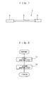
- a torsion bar 1 has a round bar shape from an overall view.
- the torsion bar 1 has such a shape that a midway area in a longitudinal direction has a spring portion 2 with small diameter, and both end areas in the longitudinal direction have joint portions 3 and 4 with a large diameter.
- the spring portion 2 has a circular section and has a uniform diameter in the longitudinal direction.
- a diameter of the joint portions 3 and 4 is larger than the diameter of the spring portion 2, and they have a circular section and a uniform diameter in the longitudinal direction.
- the size of the diameter of the spring portion 2, the joint portions 3 and 4 is not limited to this mode.
- a length relationship between the spring portion 2 and the joint portions 3 and 4 may be suitably determined according to automobiles which use the torsion bar.
- the section of the joint portions 3 and 4 is not necessarily circular.
- Portions connecting the spring portion 2 and the joint portions 3 and 4 have a round curved surface so that the diameter is gradually widened to a direction from the spring portion 2 to the joint portions 3 and 4.
- the spring portion 2 When a steering wheel is rotated in a steering apparatus such as a power steering, the spring portion 2 is twisted so as to generate a difference between a rotation phase on the side of the steering wheel and a rotation phase on the side of a steering gear box.
- the spring portion 2 allows the torsion.
- the joint portions 3 and 4 are jointed to an object to be attached in the steering apparatus.
- the joint portions 3 and 4 are provided with a spline, a serration, a through hole piercing in a radial direction, or the like (not shown), if necessary.
- This manufacturing method includes a first shaping step 11 and a second shaping step 12.
- one of spring steels SUP12 of JIS and a high carbon steel wire rods SWRH82B of JIS is selected as a matrix of the torsion bar 1 in which Vickers hardness (HV) is less than 320.
- Hardness of SUP12 and SWRH82B of JIS is about 200 by Vickers hardness (HV).
- the prepared round bar steel material undergoes cold drawing work, so that its entire diameter in the longitudinal direction is reduced to be uniform.
- a 0 denotes a cross section of the matrix before the work
- An denotes a cross section of the matrix after the final work.
- SUP12 and SWRH82B of JIS the reduction of area is set to 12 to 15%, so that the hardness of an area of the matrix including an inside through a surface layer is set to 320 or more by Vickers hardness (HV).
- the midway area of the round bar steel material with reduced diameter in the longitudinal direction is cut so as to have a smaller diameter than that of the both end areas in the longitudinal direction, thereby shaping the round bar steel material into the outer shape close to a finished product having the spring portion 2 and the joint portions 3 and 4.
- the diameter of the round bar steel material with reduced diameter shaped by cold drawing work is set to a dimension slightly larger than a finished diameter of the joint portions 3 and 4.
- the second shaping step 12 not only the spring portion 2 but also the joint portions 3 and 4 are cut, so that the diameter of the joint portions 3 and 4 is managed.
- the hardness on some places of the matrix in a depthwise direction is inspected after the first shaping step 11 and after the second shaping step 12 in a following manner.
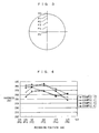
- the hardness of the joint portions 3 and 4 is measured, and measuring positions are, as shown in Fig. 3, five positions P1 to P5 in the depthwise direction.
- Theposition P1 is separated by 0.5mm from a position P0 (surface)
- the position P2 is separated by 1.0 mm from the position P0
- the position P3 is separated by 2.0 mm from the position P0
- the position P4 is separated by 3.0 mm from the position P0
- the position P5 is separated by 4.0 mm from the position P0.
- Examples 1 to 4 are prepared as samples.
- the examples 1 and 2 use SUP12 of JIS as a matrix.
- the examples 3 and 4 use SWRH82B of JIS as a matrix. Reduction of area in the examples is set to 12.6%.
- the hardness of the examples at the time of completion of the first shaping step 11 is shown in Fig. 4 and Table 1. As mentioned above, places where the hardness is measured are the joint portions 3 and 4, but at the first shaping step 11, since an outer diameter of the entire longitudinal direction of the round bar steel material as the matrix is reduced into an approximately uniform dimension, it is considered that the hardness of the joint portions 3 and 4 is approximately same as the hardness of the spring portion 2.
- the hardness of the entire portion including the inside through the surface of the round bar steel material is 320 or more to 450 or less by Vickers hardness (HV).
- Preferable Vickers hardness (HV) of the entire round bar steel material is 350 or more to 430 or less.
- HV Vickers hardness
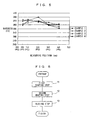
- the hardness at the time of completion of the second shaping step 12 is shown in Fig. 5 and Table 2.
- the hardness of the roundbar steel material including the inside through the surface is 320 or more to 450 or less by Vickers hardness (HV).
- HV Vickers hardness
- the reduction of area at the first shaping step 11 is set to 12 to 15%, preferably to 12.6%, so that the hardness of the spring portion 2 and the joint portions 3 and 4 are set to 320 or more by Vickers hardness (HV).
- tensile strength of the torsion bar 1 is set to 100 to 165 kg/mm 2
- fatigue limit under rotary bending is set to 48 to 70 kg/mm 2
- Fatigue strength against repeated torsion can satisfy a condition such that when a torsion stress of 300 MPa or more is applied, the repeated torsion can be carried out at least 5 x 10 6 times similarly to the prior matrices.
- the torsion bar 1 fulfills the function in the steering apparatus such as a power steering mounted to a vehicle such as an automobile.
- the torsion bar 1 of the above-mentioned mode In the case of the torsion bar 1 of the above-mentioned mode, thematrixof the torsionbar 1 is selected and is plastically deformed without undergoing heat curing treatment. As a result, cost of the matrix may rise higher than the prior matrices, but since the heat curing treatment is not carried out, production efficiency can be improved and manufacturing cost can be reduced. In the manufacturing method of the present invention, therefore, the torsion bar 1 with high quality which satisfies a predetermined performance can be manufactured at a comparatively low price.
- the present invention is not limited only to the above mode, and various applications and modifications are considered.
- blueing work which is a well known technique may be executed. That is to say, as shown in Fig. 6, the first shaping step 11, the second shaping step 12 and the blueing step 13 may be executed in this order as the manufacturing steps of the torsion bar 1.
- the first and second shaping steps 11 and 12 are the same as those in the aforementioned mode, the explanation thereof is omitted.
- the matrix is heated at ambient temperature of 200 to 350°C, for example.
- the treatment temperature is 200 to 350°C as mentioned above, namely, comparatively low.
- this step is different from the high-temperature heat treatment for heightening hardness of a prior torsion bar shaped into a finished product.
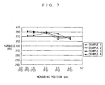
- the hardness of the spring portion 2 and the joint portion 3 and 4 can be heightened to 360 or more by bickers hardness (HV).
- the steel material which has a shape close to the finished product of the torsion bar, does not undergo the heat treatment for heightening the hardness which causes high cost unlike the prior example.
- the production efficiency can be improved and the manufacturing cost can be reduced.
- the torsion bar which satisfies the predetermined performance can be manufactured at comparatively low cost.
- the present invention can be applied to the torsion bar to be used in the steering apparatus such as a power steering mounted to a vehicle such as an automobile.
Landscapes
- Engineering & Computer Science (AREA)
- Mechanical Engineering (AREA)
- General Engineering & Computer Science (AREA)
- Springs (AREA)
- Steering Controls (AREA)
- Metal Extraction Processes (AREA)
- Heat Treatment Of Steel (AREA)
Description
- The present invention relates to a method of manufacturing a torsion bar for a steering apparatus of a vehicle such as an automobile.
- As disclosed in specifications of U. S. Patent No. 4,699,174 and U. S. Patent No. 4,550,597, steering apparatuses such as power steerings provided to vehicles such as automobiles assist rotating operation power using a power source such as a motor or a hydraulic mechanism at the time of the rotating operation of a steering wheel. A torsion bar of the present invention is unitized in order to control the operation of the power source.
- The torsion bar is used on a path for transmitting a rotating power of the steering wheel to a steering gear box. When the steering wheel is rotated, the torsion bar is twisted, so that a difference is generated between a rotation phase on the side of the steering wheel and a rotation phase on the side of the steering gear box. The phase difference is suitably detected so that the operation of the power source is controlled.
- In the torsion bar for the steering apparatus, both ends in a longitudinal direction are joint portions which are supported by an object to be attached, and a midway portion in the longitudinal direction is a spring portion which allows torsion. Such a kind of torsion bars include a torsion bar in which its entire shape is a roundbar, for example, joint portions on both ends in its longitudinal direction have large diameter, and a spring portion on a midway portion in the longitudinal direction has a small diameter.
- The torsion bar used for the above application requires predetermined fatigue strength against repeated torsion. The fatigue strength against repeated torsion is determined so as to satisfy a condition such that when a torsion stress of 300 MPa or more is applied, torsion can be carried out at least 500000 times.
- A method of manufacturing the prior torsion bar is explained. A round bar steel material with low hardness first undergoes a cutting work so as to have an outer shape which is close to a finishedproduct. The steel material having the outer shape close to the finished product by the cutting undergoes high-temperature heat treatment so as to have predetermined high hardness. Finally, warping of a matrix due to the heat treatment is corrected and distortion is removed, so that an outer diameter is adjusted. In such a manner, the prior torsion bar is first shaped into the outer shape close to the finished product of the torsion bar, and then its hardness is adjusted so as to be high.
- A main object of the present invention is to provide a method of manufacturing a torsion bar for first giving treatment which heighten a hardness of an entire round bar steel material according to cold drawing work, and working the round bar steel material into an outer shape close to a finished product of a torsion bar, so as not to require high-temperature heat treatment for heightening the hardness.
- The present invention is a method of manufacturing a torsion bar having a spring portion in a midway area in a longitudinal direction and joint portions on both ends in the longitudinal direction, including: a first shaping step of reducing a diameter of a steel material by reduction of area within a predetermined range according to cold drawing work so as to heighten a hardness of the entire steel material within a predetermined range; and a second shaping step of cutting the midway area of the steel material in the longitudinal direction so as to obtain the spring portion. The cold drawing is for plastically working a workpiece at a low temperature not higher than an annealing temperature, and reducing a diameter of a steel material via a die having a gradually smaller diameter. Cutting is one of removing work for removing an unnecessary portion of a workpiece as using a machine tool and a tool so as to work the workpiece into desired shape and dimension. The cutting includes turning and grinding.
- As one preferable mode of the present invention, the hardness of the entire steel material after the cold drawing work is 320 or more to 450 or less by Vickers hardness (HV).
- As one more preferable mode of the present invention, the reduction of area is 12 to 15%.
- In the present invention, high-temperature heat curing treatment is not carried out unlike prior examples, but plastic deformation for reducing a diameter of a steel material using the cold drawing work is executed so that the entire hardness is adjusted to be large. That is to say, since only a dimension for the plastic deformation of the steel material is determined and the heat treatment, which costs the most in the prior examples, is not carried out. The present invention is, therefore, advantageous to a reduction in manufacturing cost.
- As disclosed in Japanese Patent Application Laid-Open No. 3-189043 (1991), a torsion bar here is obtained in such a manner that a steel material whose diameter is larger than a finished diameter of joint portions of the torsion bar is used, and only a spring portion of the torsion bar is swaged. It is, however, difficult to control a length of the spring portion accurately according to the swaging. Further, since after-treatment for the swaging is not carried out, accuracy of circularity and outer diameter of the spring portion is low.
- As one more preferable mode of the present invention, the blueing step may be given to the steel material before or after the second shaping step. In this case, the hardness of the steel material can be heightened comparatively simply. Further, as the steel material, oneof SUP12 and SWRH82B of JIS can be selected.
-
- Fig. 1 is a side view illustrating a torsion bar according to a best mode of the present invention.
- Fig. 2 is a step diagram illustrating a procedure for manufacturing the torsion bar in Fig. 1.
- Fig. 3 is a sectional view illustrating a hardness measuring position of a matrix.
- Fig. 4 is a graph showing a result of inspecting the hardness of the matrix after a first shaping step.
- Fig. 5 is a graph showing a result of inspecting the hardness of the matrix after a second shaping step.
- Fig. 6 is a step diagram illustrating a procedure for manufacturing the torsion bar according to another mode of the present invention.
- Fig. 7 is a graph showing a result of inspecting the hardness of the matrix after the blueing step.
- With reference to Figs. 1 to 5, a method of manufacturing a torsion bar according to the best mode of the present invention is explained. A
torsion bar 1 has a round bar shape from an overall view. Thetorsion bar 1 has such a shape that a midway area in a longitudinal direction has aspring portion 2 with small diameter, and both end areas in the longitudinal direction havejoint portions spring portion 2 has a circular section and has a uniform diameter in the longitudinal direction. A diameter of thejoint portions spring portion 2, and they have a circular section and a uniform diameter in the longitudinal direction. The size of the diameter of thespring portion 2, thejoint portions spring portion 2 and thejoint portions joint portions - Portions connecting the
spring portion 2 and thejoint portions spring portion 2 to thejoint portions spring portion 2 is twisted so as to generate a difference between a rotation phase on the side of the steering wheel and a rotation phase on the side of a steering gear box. Thespring portion 2 allows the torsion. Thejoint portions joint portions - With reference to Fig. 2, the method of manufacturing the
torsion bar 1 is explained. This manufacturing method includes afirst shaping step 11 and asecond shaping step 12. In this mode, for example, one of spring steels SUP12 of JIS and a high carbon steel wire rods SWRH82B of JIS is selected as a matrix of thetorsion bar 1 in which Vickers hardness (HV) is less than 320. A round bar steel material, whose diameter is set to be larger than a finished diameter of thejoint portions - At the
first shaping step 11, the prepared round bar steel material undergoes cold drawing work, so that its entire diameter in the longitudinal direction is reduced to be uniform. - At the
first shaping step 11, reduction of area for the round bar steel material as the matrix is managed, so that predetermined hardness is secured. When the cold drawing work is carried out at a plurality of times, however, the reduction of area at each time and total reduction of area should be set suitably. - The reduction of area y(%) is represented by a following equation as publicly known.

- In the above equation, A0 denotes a cross section of the matrix before the work, and An denotes a cross section of the matrix after the final work. Incidentally, when SUP12 and SWRH82B of JIS are used, the reduction of area is set to 12 to 15%, so that the hardness of an area of the matrix including an inside through a surface layer is set to 320 or more by Vickers hardness (HV).
- At the
second shaping step 12, the midway area of the round bar steel material with reduced diameter in the longitudinal direction is cut so as to have a smaller diameter than that of the both end areas in the longitudinal direction, thereby shaping the round bar steel material into the outer shape close to a finished product having thespring portion 2 and thejoint portions - In this case, at the
first shaping step 11, the diameter of the round bar steel material with reduced diameter shaped by cold drawing work is set to a dimension slightly larger than a finished diameter of thejoint portions second shaping step 12, not only thespring portion 2 but also thejoint portions joint portions - The hardness on some places of the matrix in a depthwise direction is inspected after the
first shaping step 11 and after thesecond shaping step 12 in a following manner. - The hardness of the
joint portions - Examples 1 to 4 are prepared as samples. The examples 1 and 2 use SUP12 of JIS as a matrix. The examples 3 and 4 use SWRH82B of JIS as a matrix. Reduction of area in the examples is set to 12.6%.
- The hardness of the examples at the time of completion of the
first shaping step 11 is shown in Fig. 4 and Table 1. As mentioned above, places where the hardness is measured are thejoint portions first shaping step 11, since an outer diameter of the entire longitudinal direction of the round bar steel material as the matrix is reduced into an approximately uniform dimension, it is considered that the hardness of thejoint portions spring portion 2. - In the examples 1 to 4, accordingly, the hardness of the entire portion including the inside through the surface of the round bar steel material is 320 or more to 450 or less by Vickers hardness (HV). Preferable Vickers hardness (HV) of the entire round bar steel material is 350 or more to 430 or less.
[Table 1] Measuring position from outer diameter Example 1 Example 2 Example 3 Example 4 Unit (mm) Unit (HV) P1 → 0.5 340 360 390 380 P2 → 1.0 370 380 400 390 P3 → 2.0 370 370 390 400 P4 → 3.0 340 350 380 370 P5 → 4.0 360 340 350 325 - The hardness at the time of completion of the
second shaping step 12 is shown in Fig. 5 and Table 2. - In the examples 1 to 4, accordingly, the hardness of the roundbar steel material including the inside through the surface is 320 or more to 450 or less by Vickers hardness (HV).
[Table 2] Measuring position from outer diameter Example 1 Example 2 Example 3 Example 4 Unit (mm) Unit (HV) P1→0.5 350 360 380 370 P2→1.0 370 360 370 380 P3→2.0 370 370 390 360 P4→3.0 350 350 350 360 P5→4.0 340 360 330 350 - In the case where the SUP12 and SWRH82B of JIS are used as the matrix, the reduction of area at the
first shaping step 11 is set to 12 to 15%, preferably to 12.6%, so that the hardness of thespring portion 2 and thejoint portions - When the above-mentioned hardness is secured, tensile strength of the
torsion bar 1 is set to 100 to 165 kg/mm2, and fatigue limit under rotary bending is set to 48 to 70 kg/mm2. Fatigue strength against repeated torsion can satisfy a condition such that when a torsion stress of 300 MPa or more is applied, the repeated torsion can be carried out at least 5 x 10⁶ times similarly to the prior matrices. Incidentally, when the above fatigue strength against repeated torsion is secured, thetorsion bar 1 fulfills the function in the steering apparatus such as a power steering mounted to a vehicle such as an automobile. - In the case of the
torsion bar 1 of the above-mentioned mode, thematrixof thetorsionbar 1 is selected and is plastically deformed without undergoing heat curing treatment. As a result, cost of the matrix may rise higher than the prior matrices, but since the heat curing treatment is not carried out, production efficiency can be improved and manufacturing cost can be reduced. In the manufacturing method of the present invention, therefore, thetorsion bar 1 with high quality which satisfies a predetermined performance can be manufactured at a comparatively low price. - The present invention is not limited only to the above mode, and various applications and modifications are considered.
(1) In the above mode, after thesecond shaping step 12, blueing work which is a well known technique may be executed. That is to say, as shown in Fig. 6, thefirst shaping step 11, thesecond shaping step 12 and the blueingstep 13 may be executed in this order as the manufacturing steps of thetorsion bar 1.
The first and second shaping steps 11 and 12 are the same as those in the aforementioned mode, the explanation thereof is omitted. At theblueing step 13, the matrix is heated at ambient temperature of 200 to 350°C, for example. In this case, since it is an object of the blueing step to remove a residual stress in cold-formed products, the treatment temperature is 200 to 350°C as mentioned above, namely, comparatively low. For this reason, this step is different from the high-temperature heat treatment for heightening hardness of a prior torsion bar shaped into a finished product.
In this mode, at the time of completion of the blueingstep 13, as shown in Fig. 7 and following Table 3, the hardness of thespring portion 2 and thejoint portion [Table 3] Measuring position from outer diameter Example 1 Example 2 Example 3 Example 4 Unit (mm) Unit (HV) P1→0.5 370 390 390 390 P2→1.0 380 390 390 390 P3→2.0 380 390 390 390 P4→3.0 360 370 370 380 P5→4.0 370 370 360 360
(2) In the mode explained in (1), the blueingstep 13 may be executed before thesecond shaping step 12.
(3) In the above modes, after the final step, the round bar steel material which is shaped into the outer shape close to the finished product is cut, so that quality such as accuracy of an outside dimension can be further improved. In the manufacturing method explained in (1), the cutting may be carried out between thesecond shaping step 12 and the blueingstep 13. Since the cutting is not for removing warpage and distortion due to the heat curing process unlike the prior example, it only takes a short time. - As is clear from the above modes, in the manufacturing method of the present invention, the steel material, which has a shape close to the finished product of the torsion bar, does not undergo the heat treatment for heightening the hardness which causes high cost unlike the prior example. In the manufacturing method of the present invention, therefore, the production efficiency can be improved and the manufacturing cost can be reduced. In the manufacturing method of the present invention, therefore, the torsion bar which satisfies the predetermined performance can be manufactured at comparatively low cost.
- The present invention can be applied to the torsion bar to be used in the steering apparatus such as a power steering mounted to a vehicle such as an automobile.
Claims (6)
- A method of manufacturing a torsion bar (1) having a spring portion in a midway area (2) in a longitudinal direction and joint portions (3,4) on both ends in the longitudinal direction, comprising:a first shaping step of reducing a diameter of a steel material by reduction of area within a predetermined range according to cold drawing work so as to heighten a hardness of the entire steel material within a predetermined range; anda second shaping step of cutting the midway area of the steel material in the longitudinal direction so as to obtain the spring portion.
- The method of manufacturing the torsion bar according to claim 1, wherein the hardness of the entire steel material after the cold drawing work is 320 or more to 450 or less by Vickers hardness (HV).
- The method of manufacturing the torsion bar according to claim 1, wherein the reduction of area is 12 to 15%.
- The method of manufacturing the torsion bar according to claim 1, wherein at the first shaping step, the diameter of the shaped steel material with the diameter being reduced by the cold drawing work is set so as to be slightly larger than a finished diameter of the joint portions, and at the second shaping step, not only the spring portion (2) but also the joint portions (3,4) are cut so that the diameter of the joint portions is managed.
- The method of manufacturing the torsion bar according to claim 1, wherein at the first shaping step, the cold drawing work is carried out at a plurality of times, and in an equation γ = {(A0 - A1) / A0} x 100 in which the reduction of area of the steel material at each time is γ(%), a cross section of the steel material before the drawing work is A0, and a cross section of the steel material after final work of the drawing work is A1, the reduction of area is set to 12 to 15%, and the Vickers hardness (HV) is set to 320 or more
- The method of manufacturing the torsion bar according to claim 1, further comprising the blueing step of givingblueing work to the steel material before or after the second shaping step.
Applications Claiming Priority (3)
| Application Number | Priority Date | Filing Date | Title |
|---|---|---|---|
| JP2002070250 | 2002-03-14 | ||
| JP2002070250A JP3994763B2 (en) | 2002-03-14 | 2002-03-14 | Torsion bar manufacturing method and torsion bar |
| PCT/JP2003/002978 WO2003076097A1 (en) | 2002-03-14 | 2003-03-13 | Method of manufacturing torsion bar for vehicle steering device and torsion bar |
Publications (3)
| Publication Number | Publication Date |
|---|---|
| EP1484121A1 EP1484121A1 (en) | 2004-12-08 |
| EP1484121A4 EP1484121A4 (en) | 2005-12-21 |
| EP1484121B1 true EP1484121B1 (en) | 2007-05-09 |
Family
ID=27800337
Family Applications (1)
| Application Number | Title | Priority Date | Filing Date |
|---|---|---|---|
| EP03710334A Expired - Lifetime EP1484121B1 (en) | 2002-03-14 | 2003-03-13 | Method of manufacturing torsion bar for vehicle steering device |
Country Status (5)
| Country | Link |
|---|---|
| US (1) | US7159434B2 (en) |
| EP (1) | EP1484121B1 (en) |
| JP (1) | JP3994763B2 (en) |
| DE (1) | DE60313748T2 (en) |
| WO (1) | WO2003076097A1 (en) |
Families Citing this family (4)
| Publication number | Priority date | Publication date | Assignee | Title |
|---|---|---|---|---|
| JP2005153791A (en) * | 2003-11-27 | 2005-06-16 | Koyo Seiko Co Ltd | Rack and pinion type steering apparatus and method for manufacturing rack rod |
| JP2006349080A (en) * | 2005-06-17 | 2006-12-28 | Jtekt Corp | Manufacturing method of torsion bar |
| US11020827B2 (en) * | 2018-03-08 | 2021-06-01 | Steering Solutions Ip Holding Corporation | Torsion bar active length control and method of manufacturing |
| CN114248064B (en) * | 2020-09-21 | 2023-09-05 | 航天科工哈尔滨风华有限公司 | Manufacturing method of high-stability strong torsion bar spring |
Family Cites Families (11)
| Publication number | Priority date | Publication date | Assignee | Title |
|---|---|---|---|---|
| US2741833A (en) * | 1953-09-08 | 1956-04-17 | Bendix Aviat Corp | Process of shaping tubing |
| US2767837A (en) * | 1955-06-27 | 1956-10-23 | Lasalle Steel Co | Process of extruding steel |
| US2880855A (en) * | 1955-11-29 | 1959-04-07 | Lasalle Steel Co | Method of processing steel |
| US4550597A (en) | 1984-04-04 | 1985-11-05 | Trw Inc. | Method and apparatus for sensing relative movement between members |
| GB2179606B (en) | 1985-08-26 | 1988-06-15 | Bishop Arthur E | Power steering gear adjusting mechanism |
| IT1239918B (en) * | 1989-05-19 | 1993-11-23 | Mitsuba Electric Mfg Co Ltd | COLD FORGED TREE, METHOD AND DEVICE TO MANUFACTURE THE SAME |
| JPH03189043A (en) * | 1989-12-18 | 1991-08-19 | T R W S I Kk | Manufacture of torsion bar for power steering device |
| US5453139A (en) * | 1990-10-24 | 1995-09-26 | Consolidated Metal Products, Inc. | Method of making cold formed high-strength steel parts |
| JPH06142812A (en) * | 1992-11-06 | 1994-05-24 | Jidosha Kiki Co Ltd | Manufacture of torsion bar for power steering device |
| JPH11347683A (en) * | 1998-06-09 | 1999-12-21 | Tokai Rika Co Ltd | Long shaft, manufacture of long shaft and device for manufacturing long shaft |
| US5979209A (en) * | 1998-08-03 | 1999-11-09 | Allevard Ressorts Automobile | Method of forming a torsion bar with hexagonal heads |
-
2002
- 2002-03-14 JP JP2002070250A patent/JP3994763B2/en not_active Expired - Fee Related
-
2003
- 2003-03-13 DE DE60313748T patent/DE60313748T2/en not_active Expired - Lifetime
- 2003-03-13 EP EP03710334A patent/EP1484121B1/en not_active Expired - Lifetime
- 2003-03-13 WO PCT/JP2003/002978 patent/WO2003076097A1/en not_active Ceased
- 2003-03-13 US US10/501,654 patent/US7159434B2/en not_active Expired - Lifetime
Also Published As
| Publication number | Publication date |
|---|---|
| DE60313748T2 (en) | 2008-01-24 |
| WO2003076097A1 (en) | 2003-09-18 |
| DE60313748D1 (en) | 2007-06-21 |
| US7159434B2 (en) | 2007-01-09 |
| US20050115051A1 (en) | 2005-06-02 |
| JP3994763B2 (en) | 2007-10-24 |
| JP2003266118A (en) | 2003-09-24 |
| EP1484121A4 (en) | 2005-12-21 |
| EP1484121A1 (en) | 2004-12-08 |
Similar Documents
| Publication | Publication Date | Title |
|---|---|---|
| US20200056693A1 (en) | Rack bar and method for manufacturing rack bar | |
| KR102426646B1 (en) | Hollow rack bar and method of manufacturing the hollow rack bar | |
| US20200139494A1 (en) | Method for manufacturing rack bar | |
| EP1110663B1 (en) | Method of manufacturing gear | |
| CN107848017A (en) | net forging spiral bevel gear | |
| KR101633499B1 (en) | Manufacture method of Worm shaft For MDPS | |
| US7159434B2 (en) | Method of manufacturing torsion bar for vehicle steering device and torsion bar | |
| KR102345891B1 (en) | Method Of Manufacturing The Drive Shaft | |
| JP5509869B2 (en) | Manufacturing method of rack and pinion type steering device | |
| JP4817911B2 (en) | Method for forging hollow tube products | |
| JPH08135706A (en) | Vehicular wave spring and manufacture thereof | |
| EP1547904B1 (en) | Method of manufacturing rack shaft | |
| US11781633B2 (en) | Rack bar and steering apparatus | |
| CN113260552B (en) | Linear drive shaft for electric power steering device, and methods for manufacturing linear drive shaft and electric power steering device | |
| EP1666770A1 (en) | Speed reducer, method and appratus for manufacturing the speed reducer, and electric power steering device with the speed reducer | |
| EP3903962A1 (en) | Linear motion shaft for steering device, steering device, and method of manufacturing these | |
| JP2001219380A (en) | Wheel nut wrench and its manufacturing method | |
| JP2020192681A (en) | Method for manufacturing rack bar | |
| KR101497390B1 (en) | Method for manufacturing the holecutter | |
| JP5471493B2 (en) | Manufacturing method of rack and pinion type steering device | |
| KR20250148945A (en) | Manufacture method of Worm shaft For MDPS | |
| JP2010018066A (en) | Rack and pinion type steering device |
Legal Events
| Date | Code | Title | Description |
|---|---|---|---|
| PUAI | Public reference made under article 153(3) epc to a published international application that has entered the european phase |
Free format text: ORIGINAL CODE: 0009012 |
|
| 17P | Request for examination filed |
Effective date: 20040709 |
|
| AK | Designated contracting states |
Kind code of ref document: A1 Designated state(s): AT BE BG CH CY CZ DE DK EE ES FI FR GB GR HU IE IT LI LU MC NL PT RO SE SI SK TR |
|
| A4 | Supplementary search report drawn up and despatched |
Effective date: 20051109 |
|
| RIC1 | Information provided on ipc code assigned before grant |
Ipc: 7B 21C 1/00 A Ipc: 7F 16F 1/14 B Ipc: 7B 21K 1/76 B |
|
| RAP1 | Party data changed (applicant data changed or rights of an application transferred) |
Owner name: JTEKT CORPORATION |
|
| GRAP | Despatch of communication of intention to grant a patent |
Free format text: ORIGINAL CODE: EPIDOSNIGR1 |
|
| RTI1 | Title (correction) |
Free format text: METHOD OF MANUFACTURING TORSION BAR FOR VEHICLE STEERING DEVICE |
|
| GRAS | Grant fee paid |
Free format text: ORIGINAL CODE: EPIDOSNIGR3 |
|
| GRAA | (expected) grant |
Free format text: ORIGINAL CODE: 0009210 |
|
| AK | Designated contracting states |
Kind code of ref document: B1 Designated state(s): DE FR GB |
|
| REG | Reference to a national code |
Ref country code: GB Ref legal event code: FG4D |
|
| REF | Corresponds to: |
Ref document number: 60313748 Country of ref document: DE Date of ref document: 20070621 Kind code of ref document: P |
|
| ET | Fr: translation filed | ||
| PLBE | No opposition filed within time limit |
Free format text: ORIGINAL CODE: 0009261 |
|
| STAA | Information on the status of an ep patent application or granted ep patent |
Free format text: STATUS: NO OPPOSITION FILED WITHIN TIME LIMIT |
|
| 26N | No opposition filed |
Effective date: 20080212 |
|
| PGFP | Annual fee paid to national office [announced via postgrant information from national office to epo] |
Ref country code: GB Payment date: 20080312 Year of fee payment: 6 |
|
| GBPC | Gb: european patent ceased through non-payment of renewal fee |
Effective date: 20090313 |
|
| PG25 | Lapsed in a contracting state [announced via postgrant information from national office to epo] |
Ref country code: GB Free format text: LAPSE BECAUSE OF NON-PAYMENT OF DUE FEES Effective date: 20090313 |
|
| REG | Reference to a national code |
Ref country code: FR Ref legal event code: PLFP Year of fee payment: 14 |
|
| REG | Reference to a national code |
Ref country code: FR Ref legal event code: PLFP Year of fee payment: 15 |
|
| REG | Reference to a national code |
Ref country code: FR Ref legal event code: PLFP Year of fee payment: 16 |
|
| PGFP | Annual fee paid to national office [announced via postgrant information from national office to epo] |
Ref country code: FR Payment date: 20210210 Year of fee payment: 19 |
|
| PGFP | Annual fee paid to national office [announced via postgrant information from national office to epo] |
Ref country code: DE Payment date: 20210302 Year of fee payment: 19 |
|
| REG | Reference to a national code |
Ref country code: DE Ref legal event code: R119 Ref document number: 60313748 Country of ref document: DE |
|
| PG25 | Lapsed in a contracting state [announced via postgrant information from national office to epo] |
Ref country code: FR Free format text: LAPSE BECAUSE OF NON-PAYMENT OF DUE FEES Effective date: 20220331 Ref country code: DE Free format text: LAPSE BECAUSE OF NON-PAYMENT OF DUE FEES Effective date: 20221001 |