EP1484113A2 - Jaw crusher and self-propelled crushing machine having the jaw crusher - Google Patents
Jaw crusher and self-propelled crushing machine having the jaw crusher Download PDFInfo
- Publication number
- EP1484113A2 EP1484113A2 EP03257454A EP03257454A EP1484113A2 EP 1484113 A2 EP1484113 A2 EP 1484113A2 EP 03257454 A EP03257454 A EP 03257454A EP 03257454 A EP03257454 A EP 03257454A EP 1484113 A2 EP1484113 A2 EP 1484113A2
- Authority
- EP
- European Patent Office
- Prior art keywords
- tension
- toggle plate
- jaw
- swing
- link
- Prior art date
- Legal status (The legal status is an assumption and is not a legal conclusion. Google has not performed a legal analysis and makes no representation as to the accuracy of the status listed.)
- Granted
Links
Images


Classifications
-
- B—PERFORMING OPERATIONS; TRANSPORTING
- B02—CRUSHING, PULVERISING, OR DISINTEGRATING; PREPARATORY TREATMENT OF GRAIN FOR MILLING
- B02C—CRUSHING, PULVERISING, OR DISINTEGRATING IN GENERAL; MILLING GRAIN
- B02C1/00—Crushing or disintegrating by reciprocating members
- B02C1/02—Jaw crushers or pulverisers
- B02C1/04—Jaw crushers or pulverisers with single-acting jaws
-
- B—PERFORMING OPERATIONS; TRANSPORTING
- B02—CRUSHING, PULVERISING, OR DISINTEGRATING; PREPARATORY TREATMENT OF GRAIN FOR MILLING
- B02C—CRUSHING, PULVERISING, OR DISINTEGRATING IN GENERAL; MILLING GRAIN
- B02C21/00—Disintegrating plant with or without drying of the material
- B02C21/02—Transportable disintegrating plant
-
- B—PERFORMING OPERATIONS; TRANSPORTING
- B02—CRUSHING, PULVERISING, OR DISINTEGRATING; PREPARATORY TREATMENT OF GRAIN FOR MILLING
- B02C—CRUSHING, PULVERISING, OR DISINTEGRATING IN GENERAL; MILLING GRAIN
- B02C1/00—Crushing or disintegrating by reciprocating members
- B02C1/02—Jaw crushers or pulverisers
- B02C1/025—Jaw clearance or overload control
Landscapes
- Engineering & Computer Science (AREA)
- Food Science & Technology (AREA)
- Mechanical Engineering (AREA)
- Disintegrating Or Milling (AREA)
- Crushing And Grinding (AREA)
Abstract
Description
- The present invention relates to a jaw crusher which moves a jaw near to and away from the other jaw to crush raw materials and a self-propelled crushing machine having the same.
- There is a known conventional jaw crusher which moves a swing jaw near to and away from a fixed jaw to crush raw materials (for example, refer to published Japanese Patent No. 3133766, pages 5 to 8, Figs. 1 and 2).
- In this jaw crusher, the lower side of the swing jaw is supported by a reaction force receiver mechanism including a toggle plate and a toggle block. A most widely used type of reaction force receiver mechanism is a down-thrust type in which the toggle plate contacts the back of the swing jaw obliquely from upside toward downside. According to this down-thrust type, the swing jaw swings upward from downside when the swing jaw moves near to the fixed jaw.
- If a reaction force receiver mechanism having a toggle plate is used, the toggle plate is merely clamped between the toggle block and the swing jaw. This kind of jaw crusher therefore is provided with a toggle plate holder mechanism, which prevents release of the swing jaw from its engagement with the toggle plate while the swing jaw is swinging. The toggle plate holder mechanism has a tension rod whose one end is set on the swing jaw. The tension rod is positioned along the toggle plate. The other end of the tension rod is biased by a tension spring. The biasing force of the tension spring biases the swing jaw to the toggle block side, to clamp the toggle plate.
- In the reaction force receiver mechanism of the down-thrust type, the swing jaw moves upward from downside near to the fixed jaw, pressing the fixed jaw. At this time, however, the angle at which the swing jaw moves near to the fixed jaw is so small that raw materials slip on the fixed jaw. This results in a problem that the fixed jaw is worn out in a short time. Hence, another reaction force receiver mechanism of a so-called up-thrust type is known, in which the swing jaw moves near to the fixed jaw when the swing jaw swings downward from upside. In a jaw crusher having this reaction force receiver mechanism, the angle at which the swing jaw moves near to the fixed jaw is so large that raw materials hardly slip between the jaws. Accordingly, the lifetime of the jaws can be extended.
- However, in this up-thrust type, the toggle plate contacts the swing jaw obliquely upward from downside due to the structure of the reaction force receiver mechanism. Therefore, if the tension rod and tension spring are positioned along the toggle plate in the above-described manner, ends of the rod and spring protrude into a discharge space below the jaw crusher. This results in a problem that the ends of the tension rod and tension spring interfere with crushed materials being discharged by a discharge conveyer or the like.
- In order to prevent the end of the tension rod from protruding in the discharge space, the overall height of the jaw crusher has to be increased. However, in the case that the jaw crusher is mounted on the self-propelled crushing machine, the height thereof can not be increased unlimitedly due to a height limit for transportation purpose.
- The present invention has as an object to provide a jaw crusher of an up-thrust type in which a toggle plate holder mechanism can be installed without increasing the overall height, and a self-propelled crushing machine having the jaw crusher.
- A jaw crusher according to the present invention has: a fixed jaw; a swing jaw which swings relative to the fixed jaw; a reaction force receiver mechanism of an up-thrust type including a toggle plate having an end contacting the swing jaw, and a toggle plate support member which another end of the toggle plate contacts; and a toggle plate holder mechanism which holds the toggle plate between the swing jaw and the reaction force receiver mechanism, in which the toggle plate holder mechanism includes a link.
- In the jaw crusher constructed in the structure as described above, the toggle plate holder mechanism includes a link, and the structure can be arranged by changing freely the orientation of the link. Accordingly, the freedom of layout of the toggle plate holder mechanism in its height direction is enhanced. As a result, even when a reaction force receiver mechanism of an up-thrust type is adopted, for example, ends of the tension rod and tension spring constituting a biasing portion do not protrude into a discharge space from the frame, so crushed materials can be discharged without problems. In addition, the toggle plate holder mechanism can therefore be installed without changing the overall height. This is advantageous especially for a vehicle-mounted (self-propelled) jaw crusher whose height is restricted.
- Desirably in the jaw crusher according to the present invention, the reaction force receiver mechanism has an outlet clearance adjustment mechanism which moves the swing jaw near to and away from the fixed jaw through the toggle plate support member and the toggle plate, and the toggle plate holder mechanism has a biasing portion, which biases the swing jaw and the toggle plate support member to the toggle plate and is attached to the toggle plate support member.
- In the jaw crusher constructed in the structure as described above, the outlet clearance between the fixed and swing jaws is adjusted as the swing jaw is moved near to or away from the fixed jaw through the toggle plate support member and the toggle plate, by the outlet clearance adjustment mechanism. As a result, the size of crushed materials can be adjusted so that applicability of the jaw crusher is enhanced.
- At this time, the biasing portion of the toggle plate holder mechanism is attached to the toggle plate support member. Therefore, as the toggle plate support member is moved by the outlet clearance adjustment mechanism, the biasing portion of the toggle plate holder mechanism moves accordingly. As a result, the bias applied from the biasing portion to the toggle plate is not changed substantially but is kept substantially constant regardless of the size of the outlet clearance. It is hence unnecessary to adjust the bias when the outlet clearance is adjusted. The operation of adjusting the outlet clearance is simplified.
- Desirably in the jaw crusher according to the present invention, the toggle plate holder mechanism includes a tension link having an end attached to the swing jaw, a tension lever supporting another end of the tension link, a tension rod having an end attached to the tension lever, and a tension spring which biases the tension rod in an axial direction of the tension rod, and swing centers at both sides of the tension link are positioned near swing centers at both sides of the toggle plate.
- In the jaw crusher constructed in the structure as described above, the tension link swings in accordance with the toggle plate when the swing jaw swings. At this time, the swing centers at both sides of the tension link are provided near the swing centers at both sides of the toggle plate. Therefore, the swing of the tension link is approximate to the swing of the toggle plate. That is, the tension link swings about the vicinity of the swing center on the side of the tension lever, and the position of the link lever does not change substantially. Accordingly, the bias of the tension spring does not change substantially, and hence, the bias is stable while the swing jaw swings.
- Desirably in the jaw crusher according to the present invention, the toggle plate holder mechanism includes a tension link having an end attached to the swing jaw, a tension lever supporting another end of the tension link, a tension rod having an end attached to the tension lever, and a tension spring which biases the tension rod in an axial direction of the tension rod, and swing centers at both sides of the tension link are located at the same positions as swing centers at both sides of the toggle plate, when viewed in profile.
- In the jaw crusher constructed in the structure as described above, the swing centers at both sides of the tension link are located at the same positions as the swing centers at both sides of the toggle plate, when viewed in profile. Therefore, the toggle plate and the tension link are always kept parallel to each other. While the swing jaw is swinging, the swing of the toggle plate and the swing of the tension link correspond to each other. That is, the tension link swings about the swing center of the toggle plate on the side of the tension lever, so that the position of the tension lever does not change at all. Accordingly, the bias of the tension spring does not change but the bias is constant while the swing jaw is swinging. As a result, the crushing operation can be performed more stably.
- Desirably in the jaw crusher according to the present invention, the tension link has a shape having a concave, and a notch is formed, in the toggle plate, at respective positions corresponding to the swing centers at both sides of the tension link.
- Conventionally, the toggle plate is provided throughout the overall width of the swing jaw. Therefore, interference With the toggle plate may be caused if the swing centers at both sides of the tension link are located near the swing centers of the toggle plate or at the same positions as the swing centers of the toggle plate, when viewed in profile. In contrast, in the jaw crasher according to the present invention, the tension link is formed in a shape having a concave, and a notch is formed, in the toggle plate, at respective positions corresponding to the swing centers at both sides of the tension link. Therefore, the tension link and the toggle plate do not interfere with each other, but the swing centers of the tension link can be steadily located, with an easy structure, near the swing centers of the toggle plate or at the same positions as the swing centers of the toggle plate, when viewed in profile.
- Desirably in the jaw crusher according to the present invention, the toggle plate is divided into plural pieces, at a position where the tension link is provided.
- Also in the jaw crusher constructed in this structure, the toggle plate is divided at the position where the tension link is provided. Therefore, the swing centers of the tension link do not interfere with the toggle plate but can be steadily located near the swing centers of the toggle plate or at the same positions as the swing centers of the toggle plate, when viewed in profile.
- A self-propelled crushing machine according to the present invention is characterized in that the above-described jaw crusher according to the present invention is mounted on the machine.
- On the self-propelled crushing machine constructed in the structure as described above, the jaw crusher as described above is mounted. Therefore, the effects described above can be attained, and the toggle plate holder mechanism is installed without increasing the overall height. This kind of jaw crusher is hence suitably mounted on, especially, a self-propelled crushing machine whose height is limited during transportation. Further, the overall height can be kept short, so that loading ability is improved and reductions in size and weight are promoted.
- In the Drawings;
- Fig. 1 is a front view showing a self-propelled crushing machine according to an embodiment of the present invention;
- Fig. 2 is a rear view showing the self-propelled crushing machine;
- Fig. 3 is a right side view showing the self-propelled crushing machine;
- Fig. 4 is a left side view showing the self-propelled crushing machine;
- Fig. 5 is a plan view showing the self-propelled crushing machine;
- Fig. 6 is a sectional view showing a jaw crusher of the self-propelled crushing machine;
- Fig. 7 is an enlarged sectional view showing a toggle plate holder mechanism of the jaw crusher;
- Fig. 8 is a plane sectional view showing a toggle plate holder mechanism of the jaw crusher;
- Fig. 9 is an enlarged sectional view showing a modified toggle plate holder mechanism;
- Fig. 10 is a plane sectional view showing the toggle plate holder mechanism of Fig. 9;
- Fig. 11 is an enlarged sectional view showing another modified toggle plate holder mechanism;
- Fig. 12 is a plane sectional view showing the toggle plate holder mechanism of Fig. 11;
- Fig. 13 is an enlarged sectional view showing a further modified toggle plate holder mechanism; and
- Fig. 14 is a plane sectional view showing the toggle plate holder mechanism of Fig. 13.
-
- Hereinafter, an embodiment of the present invention will be described on the basis of the drawings.
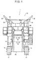
- Figs. 1 to 5 are respectively a front view, rear view, right side view, left side view, and plan view of a self-propelled crushing machine according to a present embodiment. In the present embodiment, the right side in Fig. 3 is referred to as the front side of the structure, as well as the left side as the rear side, for the sake of conveniences in explanation.
- A self-propelled crushing
machine 1 may be used to crush concrete lumps and asphalt lumps at a building demolition site or the like. In case of the present embodiment, however, the machine is used exclusively to crush coarsely big rocks and fieldstones into predetermined grain sizes at a mine, quarry, or the like. Therefore, the machine in this embodiment is large in each of overall length, width, and height, and classified into a large-scale self-propelled crushing machine. - This self-propelled crushing
machine 1 includes amain unit 10 having a pair of lower travelingmembers 11, afeed unit 20 mounted in the rear of themain unit 10 and supplied with raw materials, ajaw crusher 30 mounted in the front of thefeed unit 20, apower unit 40 further mounted in the front of thejaw crusher 30, and adischarge conveyor 50 extending obliquely upward in a frontward direction from between a pair ofcrawlers 18 below themain unit 10. - The
main unit 10 has a main frame (track frame) 14 consisting of left and right side frames 12 each continuous in the longitudinal direction and plural link frames 13 (Fig. 2) linking the side frames to each other. Thelower traveling members 11 are respectively assembled on the lower sides of the side frames 12. Each lower traveling member is constructed in a structure in which acrawler 18 is wound around afront sprocket 16 driven by ahydraulic motor 15 and arear idler 17. - The
feed unit 20 has arear frame 23 in which left and right side frames 21 protruding rearward are linked to each other by a substantiallyrectangular link frame 22 having anopening 22A. Agrizzly feeder 24 is set above therear frame 23 with plural coil springs inserted therebetween. Thegrizzly feeder 24 is driven by avibrator 25. Ahopper 26 is provided above thegrizzly feeder 24, covering the feeder from its three sides. Raw materials are thrown into thehopper 26 whose opening widens upward. Provided below thegrizzly feeder 24 is adischarge chute 27 which guides raw materials sorted and dropped by a grizzly to thedischarge conveyor 50 below. In thehopper 26 of the present embodiment, the left andright wings 28 are provided to be foldable relative to the main body, and can be folded downward by releasing the upper end of the support bars 29. Consequently, the overall height of thefeed unit 20 becomes short, restriction of the transportation by a trailer can be satisfied. - As shown in Fig. 6, the
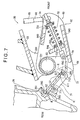
jaw crusher 30 has acrusher frame 34 in which left and rightside wall plates 31 are linked to each other by arear wall plate 32 and across member 33. Therear wall plate 32 is reinforced by plural ribs. A fixedjaw 35 is attached to the inside of therear wall plate 32. Aswing jaw 36 whose tooth surface stands substantially vertically is provided in the front of the fixedjaw 35. Theswing jaw 36 hangs, in its upper side, on an eccentric part of amain shaft 37 which is rotatably bridged between theside wall plates 31. Theswing jaw 36 is also supported, in its lower side, by a reaction force receive link mechanism (reaction force receiver mechanism) 60 which receives reaction force generated by crushing. Further, a tension link mechanism (toggle plate holder mechanism) 70 constantly biases theswing jaw 36 to the reaction force receivelink mechanism 60. - The reaction force receive
link mechanism 60 substantially includes atoggle plate 61 having an end engaged on a rear part of theswing jaw 36, toggle links (toggle plate support members) 64 which support the other end of thetoggle plate 61 and rotate about thelink pin 63 as a rotation center thereof, and bearlock cylinders 65 having lower ends pivoted on the toggle links 64. Eachbear lock cylinder 65 is rotatably pivoted on the side of the cross member 33 (trunnion structure). Further, therod 66 of eachbear lock cylinder 65 is extended and retracted so that an outlet clearance W between the lower ends of thejaws link mechanism 60 serves as an outlet clearance adjustment link mechanism (outlet clearance adjustment mechanism) 62 which moves theswing jaw 36 near to and away from the fixedjaw 35 through the toggle links 64 and thetoggle plate 61 by driving thebear lock cylinders 65. - The
tension link mechanism 70 is positioned at the substantial center of the reaction force receivelink mechanism 60. Themechanism 70 substantially includes atension link 71 having an end pivoted on the side of theswing jaw 36, atension lever 72 rotatably pivoted on afixed link pin 63, atension rod 73 having an end pivoted on thetension lever 72, and a tension spring (biasing portion) 74 which biases thetension rod 73 in a predetermined direction. Thetension rod 73 and thetension spring 74 are assembled on the toggle links 64. - In the
jaw crusher 30 as described above, apulley 38 provided at an end of amain shaft 37 is driven by ahydraulic motor 39 through a V-belt. With the rotation of themain shaft 37, theswing jaw 36 functions as a swinging link and crushes raw materials between theswing jaw 36 and the fixedjaw 35. At this time, in thejaw crusher 30 according to the present embodiment, the reaction force receivelink mechanism 60 adopts the up-thrust type, so that theswing jaw 36 swings downward from upside as if the tooth surface of the fixedjaw 35 is scraped. - The
power unit 40 has abase frame 42 in which left and right side frames 41 are linked to each other by plural link frames (not shown). An engine, hydraulic pump,fuel tank 43, operatingoil tank 44, and the like are mounted on thebase frame 42 with use of appropriate mount brackets and cross members. A control valve is contained in a container space surrounded bybase frame 42. The control valve distributes the hydraulic pressure of the hydraulic pump to the hydraulic motor for thelower traveling members 11, avibrator 25 of thegrizzly feeder 24, thehydraulic motor 39 of thejaw crusher 30, a hydraulic motor for driving thedischarge conveyor 50, and the like. - A rear part of the
discharge conveyor 50 is positioned in the rear of the discharge port at the lower end of thedischarge chute 27. Thedischarge conveyor 50 discharges frontward uncrushed raw materials discharged from thechute 27 and crushed materials dropped from the outlet of thejaw crusher 30, to drop and accumulate those materials from a height. If foreign materials such as rebar, metal strips, and the like are contained in raw materials, a magnetic ore separator may be mounted in the front of thedischarge conveyor 50 to remove those foreign materials. In place of accumulating crushed materials from thedischarge conveyor 50 on the ground, crushed materials may be conveyed to a remote place by secondary and tertiary conveyors or the like. - Details of the
jaw crusher 30 will now be described. - In Fig. 6, the
jaw crusher 30 has the fixedjaw 35 fixed to therear wall plate 32, and theswing jaw 36 which swings relative to the fixedjaw 35, as described above. Provided on the rear surface of theswing jaw 36 are the reaction force receivelink mechanism 60 which receives reaction force from theswing jaw 36, and thetension link mechanism 70 which biases theswing jaw 36 with a predetermined bias toward the reaction force receivelink mechanism 60. - The reaction force receive
link mechanism 60 includes a link having thetoggle plate 61, toggle links 64, and bearlock cylinders 65, as described above. - As shown in Figs. 7 and 8, the
toggle plate 61 is a plate-like member which contacts the rear surface of theswing jaw 36 throughout the overall width of thejaw 36. Thetoggle plate 61 contacts theswing jaw 36 in an oblique upward direction from downside, so that the reaction force receivelink mechanism 60 is of the up-thrust type. An end of thetoggle plate 61 contacts acontact portion 361 provided on the rear surface of theswing jaw 36. The other end of thetoggle plate 61 contacts contactportions 641 provided on the toggle links 64. Thus, thetoggle plate 61 is sandwiched between theswing jaw 36 and the toggle links 64.Concave portions contact portions toggle plate 61 can swing about swinging centers S2 which are the centers of the arcs of theconcave portions toggle plate 61, anotch 611 is formed on the side close to the toggle links 64. - Two
toggle links 64 are provided inside and near theside wall plates 31, and are linked to each other by alink portion 643 integrally bridged between the toggle links 64. Amount portion 644 to which thetension spring 74 is attached is integrally formed on thelink portion 643. These toggle links 64 are each pivoted on afixed link pin 63. Two fixed link pins 63 are provided coaxially with each other inside theside wall plates 31. First ends of these pins, which are far from each other, are fixed to theside wall plates 31. Second ends of the pins, which are close to each other, are fixed to amount plate 331 protruding downward from thecross member 33. - The toggle links 64 are respectively provided with the
contact portions 641 described above. End portions of thetoggle plate 61, on both sides of thenotch 611, contact thecontact portions 641, respectively. - The
bear lock cylinders 65 are respectively provided in the front of the twotoggle links 64. As shown in Fig. 6, eachbear lock cylinder 65 has therod 66 and acylinder body 67 for extending and retracting therod 66. Eachbear lock cylinder 65 is arranged to stand with therod 66 situated in the lower side of thecylinder body 67. The lower ends of therods 66 are respectively pivoted on the front ends of the toggle links 64. A portion of eachcylinder body 67 near the end thereof through which therod 66 extends and retracts, i.e., the lower side (head side) of the cylinder body is rotatably supported by asupport portion 68 of the trunnion structure. Thissupport portion 68 has asupport shaft 681 integrally formed on and protruding from both sides of thecylinder body 67, and a bearing portion not shown but supporting rotatably thesupport shaft 681. An end of thesupport shaft 681 is pivoted on one of theside wall plates 31. The other end of thesupport shaft 681 is pivoted on themount plate 332 protruded from thecross member 33. Thus, thebear lock cylinders 65 are positioned near theside wall plates 31. - In each of these
bear lock cylinders 65, therod 66 or the piston at an end of therod 66 interference-fits thecylinder body 67, and both of the rod and thecylinder body 67 are usually locked. If hydraulic pressure is applied to the interference-fitting portions through therods 66, the circumferential walls of thecylinder bodies 67 expand, reducing resistance between thecylinder bodies 67 and therods 66. The lock is then released so that therods 66 can extend and retract relative to thecylinder bodies 67. Therefore, therods 66 can be locked at arbitrary positions in thecylinder bodies 67. - According to this reaction force receive
link mechanism 60, the reaction force generated when raw materials are crushed is received by the fixedlink pin 63 of the toggle links 64 and thesupport portions 68 ofbear lock cylinders 65 through thetoggle plate 61. If, as described above, hydraulic pressure is applied between the pistons of thebear lock cylinders 65 and thecylinder bodies 67 to release the lock and if therods 66 are extended and retracted, theswing jaw 36 is moved near to and away from the fixedjaw 35 by the toggle links 64 and thetoggle plate 61. That is, the reaction force receivelink mechanism 60 also functions as the outlet clearanceadjustment link mechanism 62. - The
tension link mechanism 70 is provided at the substantial center in the width direction of the swing jaw, between twotoggle links 64 as shown in Figs. 7 and 8. Thetension link mechanism 70 is a link mechanism having thetension link 71,tension lever 72,tension rod 73, andtension spring 74, as described above. - The
tension link 71 is substantially L-shaped. An end of thetension link 71 is pivoted on arotation center shaft 711 of amount portion 363 provided on theswing jaw 36. The other end of thetension link 71 is pivoted on arotation center axis 712 of thetension lever 72. The tension link 71 can therefore swing about the substantial centers of therotation center shafts tension link 71, which is close to thetension lever 72, is positioned inside thenotch 611 of thetoggle plate 61, so that the tension link might not interfere with thetoggle plate 61. - The swing centers S1 are arranged near the swing centers S2 of the
toggle plate 61, so that the swing of thetension link 71 is approximate to the swing of thetoggle plate 61. - The
tension lever 72 has ashaft portion 721 rotatably supported by the fixed link pins 63, andlever portions 722 which rotate about theshaft portion 721. Theshaft portion 721 is formed in a cylindrical shape having two ends supported between those ends of the fixed link pins 63 that are close to each other. A pair oflever portions 722 are provided vertically below theshaft portion 721. Thetension link 71 is set on a rear lower end of thelever portion 722, and an end of thetension rod 73 is set on a front lower end of thelever portion 722. - The
tension rod 73 penetrates themount portion 644 of the toggle links 64, and is arranged in an obliquely upward direction to the front side from the mount portion of thetension lever 72. Thetension rod 73 is inserted in thetension spring 74. Thetension spring 74 has a top end contacting acontact portion 731 screwed on the tension rod. The bottom end of the tension spring is made contact acontact portion 732 fixed to themount portion 644. Thus, thetension spring 74 biases thetension rod 73 to the toggle links 64 with a predetermined bias (tension). Specifically, thetension spring 74 biases theswing jaw 36 to the toggle links 64 through thetension rod 73,tension lever 72, andtension link 71. This biasing steadily holds thetoggle plate 61 between theswing jaw 36 and the toggle links 64. - Hereinafter, the operation of the
jaw crusher 30 will be explained. - At first, the
hydraulic motor 39 is driven to rotate thepulley 38 through the V-belt and further themain shaft 37. Theswing jaw 36 pivoted on the eccentric part of themain shaft 37 then swings. At this time, thetoggle plate 61 swings about the swing center S2 at the side of the toggle links 64 because theswing jaw 36 is supported at its lower side by the reaction force receivelink mechanism 60 of the up-thrust type. Accordingly, theswing jaw 36 swings to move near to and away from the fixed jaw. By this swinging action, theswing jaw 36 and the fixedjaw 35 crush raw materials thrown between both jaws, and discharge crushed materials to thedischarge conveyor 50 from the outlet clearance W between the lower ends. - Further, the reaction force generated when the
swing jaw 36 crushes raw materials is received by the fixedlink pin 63 of the toggle links 64 and thesupport portions 68 of thebear lock cylinders 65. If the reaction force received by theswing jaw 36 is too large, the interference-fitting portions of thebear lock cylinders 65 slide to prevent damages on the toggle links 64 and thebear lock cylinders 65. - Meanwhile, to change the grain size of crushed materials, the outlet clearance
adjustment link mechanism 62 is operated. Hydraulic pressure is applied between the pistons of thebear lock cylinders 65 and thecylinder bodies 67, so that thecylinder bodies 67 are slightly expanded to reduce resistance between them. The lock depending on the interference-fit is thus released. In this state, hydraulic pressure is applied to the side of the heads of thecylinder bodies 67 or to the side of the bottoms, to extend and retract therods 66. Accordingly, the toggle links 64 rotate about the fixedlink pin 63. Thetoggle plate 61 then moves so that theswing jaw 36 moves near to or away from the fixedjaw 35. The outlet clearance W between the lower ends of theswing jaw 36 and the fixedjaw 35 is thus adjusted to change the grain size of the crushed materials. - At this time, in the
tension link mechanism 70, thetension link 71 moves and thetension lever 72 rotates, as theswing jaw 36 moves near to and away from the fixedjaw 35. Also at this time, the swing centers S1 of thetension link 71 are respectively near the swing centers S2 of thetoggle plate 61. The rotation centers of thetension lever 72 and the toggle links 64 are the common fixedlink pin 63. Therefore, the trajectory of thetension link 71 is approximate to the trajectory of thetoggle plate 61. Thetension lever 72 accordingly rotates by an angle substantially equal to the rotation angle of the toggle links 64. As a result, thecontact portion 731 of thetension rod 73 attached to thetension lever 72 and thecontact portion 732 fixed to themount portion 644 of the toggle links 64 does not substantially change their positions relative to each other. The bias of thetension spring 74 is kept substantially constant even when the outlet clearance W is changed. - The following advantages are obtained from the above embodiment.
- (1) The
tension link mechanism 70 constitutes a link having thetension link 71,tension lever 72,tension rod 73, andtension spring 74. Therefore, the layout angles of thetension link 71 and thetension rod 73 at thetension lever 72 can be changed so that the freedom of layout in the height direction can be enhanced. Accordingly, thetension rod 73 can be positioned obliquely upward in a frontward direction. Therefore, thetension rod 73 and thetension spring 74 do not protrude toward thedischarge conveyor 50 below theswing jaw 36, and crushed materials can be discharged excellently. On the contrary, even in the jaw crusher including the reaction force receivelink mechanism 60 of the up-thrust type, thetension link mechanism 70 can be positioned without increasing the overall height. Hence, the height limit is surely satisfied even when thejaw crusher 30 is mounted on a self-propelled crushingmachine 1. - (2) The
tension spring 74 is held between the top end of thetension rod 73 and themount portion 644 of the toggle links 64, by thecontact portions swing jaw 36 moves, to adjust the outlet clearance. Thecontact portion 732 then also moves. At this time, thetension rod 73 moves together through thetension link 71 and thetension lever 72, so that the bias of thetension spring 74 is not substantially changed. Accordingly, it is unnecessary to reset the bias of thetension spring 74 when the outlet clearance is adjusted. The outlet clearance adjustment can be achieved simply in a short time. - (3) When the
swing jaw 36 swings, thetoggle plate 61 swings about the swing center S2 at the side of the toggle links 64. At this time, the swing centers S1 of thetension link 71 are positioned near the swing centers S2 at both sides of thetoggle plate 61, the swings of thetoggle plate 61 and thetension link 71 are approximate to each other. That is, thetension link 71 swings about theswing center S 1 on the side of thetension lever 72 as the center of the swing, and the position of thetension lever 72 is not changed substantially. Accordingly, thetension spring 74 does not substantially expand or contract, but stable bias can be attained. -
- Note that the present invention is not limited to the embodiment described above but includes modifications and changes as far as the objects of the invention are achieved.
- For example, the swing centers S1 of the
tension link 71 are positioned near the swing centers S2 at both sides of thetoggle plate 61. The present invention is not limited hitherto. As shown in Figs. 9 and 10, the swing centers S1 may be at the same positions as the swing centers S2 at both sides of thetoggle plate 61, when viewed in profile. In Figs. 9 and 10, thetension link 71 is formed linearly in the longitudinal direction and is positioned in the substantial center in the width direction of theswing jaw 36. Thetoggle plate 61 is divided at the substantial center where thetension link 71 is positioned into two pieces each of which is sandwiched between thecontact portions - According to this structure, the swing centers S1 of the
tension link 71 can be arranged at the same positions as the swing centers S2 of thetoggle plate 61, when viewed in profile. Therefore, when theswing jaw 36 swings, thetension link 71 behaves in the same manner as the swing of thetoggle plate 61. Accordingly, when theswing jaw 36 swings, thetension link 71 swings about the swing center S1 on the side of thetension lever 72 but the tension lever does not rotate at all. Therefore, the bias of thetension spring 74 does not change at all, so that more stable bias can be attained. - Note that the
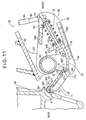
toggle plate 61 need not be divided limitedly into two pieces but may be divided into a number of pieces corresponding to the number of providedtension link mechanisms 70. - Alternatively, as shown in Figs. 11 and 12,
notches 611 may be provided respectively at the both sides of thetoggle plate 61, and the both ends of thetension link 71 may be positioned inside thesenotches 611. In Figs. 11 and 12,notches 611 are formed on both ends of thetoggle plate 61 at the substantial center of thetoggle plate 61 in its width direction. Both ends of thetension link 71, which has a shape having a concave when viewed in profile, are positioned inside thesenotches 611. At an end of thetension link 71, the swing center S1 on the side of theswing jaw 36 is at the same position as the swing center S2 of thetoggle plate 61, when viewed in profile. The other swing center S1 on the side of thetension lever 72 is positioned near a swing center S2 of thetoggle plate 61, when viewed in profile. According to this structure, the swing centers S1 can be located near the swing centers S2 of thetoggle plate 61 or at the same positions as the swing centers S2, when viewed in profile, without causing interference between both ends of thetension link 71 and thetoggle plate 61. Thus, the bias of thetension spring 74 can be stabled. Also according to this structure, thenotches 611 are formed in thetoggle plate 61, so that theswing jaw 36 can be supported by the onesingle toggle plate 61 throughout the overall width of thejaw 36. Therefore, one-sided abrasion of thetoggle plate 61 can be prevented from occurring even from a long-time use. The durability of thetoggle plate 61 can thus be improved. - In the structure shown in Figs. 9 and 10, the positions of the swing centers S1 may both be near the swing centers S2 of the
toggle plate 61, or only one of the swing centers S1 may be located near one of the swing centers S2. Also in Figs. 11 and 12, both of the swing centers S1 may be near the swing centers S2 or may be at the same positions as the swing centers S2 when viewed in profile. Alternatively, on the contrary to these figures, the swing centers S1 may be located near the swing centers S2 or at the same positions as the swing centers S2 when viewed in profile. - The
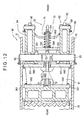
tension link mechanism 70 is provided in the substantial center of theswing jaw 36 in its width direction. However, as shown in Figs. 13 and 14, a pair of tension link mechanisms may be provided on both sides of thetoggle plate 61. In Figs. 13 and 14, the toggle links 64 are provided close to each other, and are linked to each other by acylindrical link portion 643. The toggle links 64 are fixed to arotation link pin 69. Therefore, therotation link pin 69 rotates together withtoggle links 64. Therotation link pin 69 is rotatably supported bymount portions 333 each of which has a substantially center portion protruding below thecross member 33. - The tension levers 72 are supported individually rotatably by the
rotation link pin 69. Thetension rod 73 is supported by amount portion 644 protruded from the toggle links 64 through atension spring 74. - The
bear lock cylinders 65 are rotatably supported by themount portions 334 protruded upward from thecross member 33, on the far side of thecylinder bodies 67 from therods 66, i.e., on the bottom side of thecylinder bodies 67. - In the jaw crusher having this structure, the
tension link mechanism 70 includes links. Therefore, thetension rod 73 and thetension spring 74 do not protrude to the side of thedischarge conveyor 50 but excellent discharging performance can be achieved. When therods 66 of thebear lock cylinders 65 are extended and retracted, the toggle links 64 rotate together with therotation link 69, so that the outlet clearance W between theswing jaw 36 and the fixedjaw 35 can be adjusted like the foregoing embodiment. At this time, since thetension spring 74 is attached to the toggle links 64, the bias does not substantially change even if the outlet clearance is adjusted. It is hence unnecessary to adjust the bias, and the outlet clearance adjustment can be achieved easily. - The
jaw crusher 30 according to the present invention has been described to be mounted on the self-propelled crushingmachine 1. However, the present invention is not limited hitherto but thejaw crusher 30 may be used as a permanently fixed type. Also in this case, thetension rod 73 and thetension spring 74 can be structured so as not to interfere with thedischarge conveyor 50 without increasing the overall height. Excellent discharging performance can hence be achieved. - The best structures and methods to practice the present invention have been disclosed in the description above. The present invention however is not limited to the description. Although the present invention has been illustrated and described mainly based on a specific embodiment, a skilled person in the art will be able to variously modify the embodiment described above with respect to shapes, materials, quantities, and any other structures of components constituting the present invention, without deviating from the scope of the technical ideas and objects of the invention.
- Therefore, those parts of the above description that disclose shapes, materials, and the like are merely examples which help understanding of the present invention and do not limit the scope of the present invention. The present invention includes such description that uses names excluding part or all of limitations to those shapes, materials, and the like.
Claims (7)
- A jaw crusher (30) comprising:a fixed jaw (35);a swing jaw (36) which swings relative to the fixed jaw (35);a reaction force receiver mechanism (60) of an up-thrust type including a toggle plate (61) having an end contacting the swing jaw (36), and a toggle plate support member (64) which another end of the toggle plate (61) contacts; anda toggle plate holder mechanism (70) which holds the toggle plate (61) between the swing jaw (36) and the reaction force receiver mechanism (60), whereinthe toggle plate holder mechanism (70) is comprised of a link.
- The jaw crusher (30) according to claim 1, wherein
the reaction force receiver mechanism (60) has an outlet clearance adjustment mechanism (62) which moves the swing jaw (36) near to and away from the fixed jaw (35) through the toggle plate support member (64) and the toggle plate (61), and
the toggle plate holder mechanism (70) has a biasing portion (74), which biases the swing jaw (36) and the toggle plate support member (64) to the toggle plate (61) and is attached to the toggle plate support member (64). - The jaw crusher (30) according to claim 1 or 2, wherein
the toggle plate holder mechanism (70) includes a tension link (71) having an end attached to the swing jaw (36), a tension lever (72) supporting another end of the tension link (71), a tension rod (73) having an end attached to the tension lever (72), and a tension spring (74) which biases the tension rod (73) in an axial direction of the tension rod (73), and
swing centers (S1) at two sides of the tension link (71) are positioned near swing centers (S2) at two sides of the toggle plate (61). - The jaw crusher (30) according to claim 1 or 2, wherein
the toggle plate holder mechanism (70) includes a tension link (71) having an end attached to the swing jaw (36), a tension lever (72) supporting another end of the tension link (71), a tension rod (73) having an end attached to the tension lever (72), and a tension spring (74) which biases the tension rod (73) in an axial direction of the tension rod (73), and
swing centers (S1) at two sides of the tension link (71) are located at the same positions as swing centers (S2) at two sides of the toggle plate (61), when viewed in profile. - The jaw crusher (30) according to claim 3 or 4, wherein
the tension link (71) has a shape having a concave, and
a notch (611) is formed, in the toggle plate (61), at respective positions corresponding to the swing centers (S1) at two sides of the tension link (71). - The jaw crusher (30) according to claim 3 or 4, wherein the toggle plate (61) is divided into plural pieces, at a position where the tension link (71) is provided.
- A self-propelled crushing machine (1) on which the jaw crusher (30) according to any of claims 1 to 6 is mounted.
Applications Claiming Priority (2)
| Application Number | Priority Date | Filing Date | Title |
|---|---|---|---|
| JP2002346464A JP4109539B2 (en) | 2002-11-28 | 2002-11-28 | Jaw crusher and self-propelled crusher equipped with the same |
| JP2002346464 | 2002-11-28 |
Publications (3)
| Publication Number | Publication Date |
|---|---|
| EP1484113A2 true EP1484113A2 (en) | 2004-12-08 |
| EP1484113A3 EP1484113A3 (en) | 2005-08-10 |
| EP1484113B1 EP1484113B1 (en) | 2007-07-04 |
Family
ID=32677041
Family Applications (1)
| Application Number | Title | Priority Date | Filing Date |
|---|---|---|---|
| EP03257454A Expired - Lifetime EP1484113B1 (en) | 2002-11-28 | 2003-11-26 | Jaw crusher and self-propelled crushing machine having the jaw crusher |
Country Status (8)
| Country | Link |
|---|---|
| US (1) | US7168644B2 (en) |
| EP (1) | EP1484113B1 (en) |
| JP (1) | JP4109539B2 (en) |
| KR (1) | KR100987690B1 (en) |
| CN (1) | CN100371080C (en) |
| AT (1) | ATE366138T1 (en) |
| DE (1) | DE60314729T2 (en) |
| ES (1) | ES2287422T3 (en) |
Cited By (2)
| Publication number | Priority date | Publication date | Assignee | Title |
|---|---|---|---|---|
| CN101607220B (en) * | 2008-06-20 | 2012-08-29 | 启铭机械股份有限公司 | Jaw crusher |
| EP3750632A1 (en) * | 2019-06-11 | 2020-12-16 | Kleemann Gmbh | Feed unit for a treatment plant, in particular a crushing or screening plant |
Families Citing this family (15)
| Publication number | Priority date | Publication date | Assignee | Title |
|---|---|---|---|---|
| JP4119231B2 (en) * | 2002-11-28 | 2008-07-16 | 株式会社小松製作所 | Jaw crusher |
| US7708218B2 (en) | 2005-08-29 | 2010-05-04 | Komatsu Ltd. | Jaw crusher and self-traveling crusher |
| JP4879903B2 (en) | 2005-08-29 | 2012-02-22 | 株式会社小松製作所 | Jaw crusher and self-propelled crusher |
| EP1804282A1 (en) * | 2005-12-29 | 2007-07-04 | Interuniversitair Microelektronica Centrum vzw ( IMEC) | Methods for manufacturing dense integrated circuits |
| JP5525741B2 (en) * | 2008-05-14 | 2014-06-18 | 株式会社小松製作所 | Self-propelled crusher |
| JP5466867B2 (en) * | 2008-05-28 | 2014-04-09 | 株式会社小松製作所 | Self-propelled crusher |
| AT509476B1 (en) * | 2010-03-11 | 2013-04-15 | Hartl Stefan | CRUSHER |
| KR101015169B1 (en) * | 2010-05-28 | 2011-02-17 | 주식회사 신흥밸브 | Box unit for water-meter |
| CN103752394A (en) * | 2014-02-10 | 2014-04-30 | 上海建冶路桥机器设备有限公司 | Environment-friendly aggregate series mobile crushing station |
| ES2690076T3 (en) * | 2015-03-26 | 2018-11-19 | Aracama Martínez De Lahidalga, Javier | Stone crusher dipper and the like |
| CN104984780B (en) * | 2015-07-17 | 2017-12-19 | 中国铁建重工集团有限公司 | A kind of mud channel disintegrating machine being used in shield machine |
| US20180071742A1 (en) * | 2016-09-13 | 2018-03-15 | Superior Industries, Inc. | Jaw crusher systems, methods, and apparatus |
| DE102019120580B4 (en) * | 2019-07-30 | 2021-04-01 | Kleemann Gmbh | Rock processing machine |
| DE102019120582A1 (en) * | 2019-07-30 | 2021-02-04 | Kleemann Gmbh | Rock processing plant |
| US11602755B2 (en) | 2019-08-27 | 2023-03-14 | Eagle Crusher Company, Inc. | Crusher with resettable relief system |
Citations (4)
| Publication number | Priority date | Publication date | Assignee | Title |
|---|---|---|---|---|
| FR1348462A (en) * | 1961-11-16 | 1964-01-10 | ||
| JPS57110340A (en) * | 1980-12-29 | 1982-07-09 | Tateishi Kensetsu Kogyo Kk | Shock absorber for upper section of fixed tooth of jaw crusher |
| DE19956200A1 (en) * | 1999-11-23 | 2001-06-21 | Horst Maurer | Crank vibration breaker is formed as jaw breaker with vibrating jaws, fixed jaw as buttress, breaker housing, pressure plate system with drawback rods |
| US6375105B1 (en) * | 2000-03-21 | 2002-04-23 | Astec Industries, Inc. | Jaw crusher toggle beam hydraulic relief and clearing |
Family Cites Families (19)
| Publication number | Priority date | Publication date | Assignee | Title |
|---|---|---|---|---|
| US1620078A (en) * | 1923-01-08 | 1927-03-08 | Acme Road Machinery Company | Stone crusher |
| US2259833A (en) * | 1939-02-06 | 1941-10-21 | Sandy Thomas | Rock crushing device |
| US3918648A (en) * | 1974-05-31 | 1975-11-11 | Fuller Co | Relief mechanism for jaw crusher |
| FR2460716A1 (en) | 1979-07-06 | 1981-01-30 | Fives Cail Babcock | CRUSHER OR SHREDDER MACHINE WITH ADJUSTMENT AND SAFETY SYSTEM |
| JPS57110342A (en) * | 1980-12-29 | 1982-07-09 | Tateishi Kensetsu Kogyo Kk | Tooth for jaw crusher |
| JPS63118490A (en) | 1986-11-04 | 1988-05-23 | 株式会社郷鉄工所 | Crusher with safety device having automatic set adjusting mechanism |
| GB2274608B (en) * | 1993-02-01 | 1996-03-06 | Brown Lenox & Co Ltd | A cantilevered swing jaw crushing apparatus |
| IT230941Y1 (en) | 1993-09-15 | 1999-07-05 | Ponzano Veneto S P A Off Mec D | JAW CRUSHING MACHINE PARTICULARLY SUITABLE FOR THE RECYCLING OF MATERIALS |
| JP2808236B2 (en) * | 1994-05-17 | 1998-10-08 | コトブキ技研工業株式会社 | Jaw crusher toggle block position adjusting method and apparatus used in the method |
| JP3660742B2 (en) * | 1996-03-25 | 2005-06-15 | 株式会社神戸製鋼所 | Jaw crusher outlet clearance adjustment device |
| CN2257215Y (en) * | 1996-03-28 | 1997-07-02 | 敖杰俊 | Crusher |
| JP3133766B2 (en) | 1996-03-29 | 2001-02-13 | 株式会社小松製作所 | Jaw crusher outlet clearance adjustment mechanism |
| KR0176297B1 (en) * | 1996-07-12 | 1999-03-20 | 박병준 | Device for controlling the exit distance of jaw-crusher |
| GB9617917D0 (en) | 1996-08-28 | 1996-10-09 | Pratt Gerald C | Improvements in or relating to crushing machines |
| JP2945346B2 (en) | 1997-03-07 | 1999-09-06 | 川崎重工業株式会社 | Jaw crusher |
| CN2385794Y (en) * | 1999-08-27 | 2000-07-05 | 朱广礼 | Jaw crusher |
| JP4247807B2 (en) * | 2000-09-26 | 2009-04-02 | 株式会社小松製作所 | Jaw crusher outlet clearance adjustment mechanism |
| GB0025888D0 (en) | 2000-10-23 | 2000-12-06 | Extec Ind Plc | Jaw crusher unit |
| JP4119231B2 (en) | 2002-11-28 | 2008-07-16 | 株式会社小松製作所 | Jaw crusher |
-
2002
- 2002-11-28 JP JP2002346464A patent/JP4109539B2/en not_active Expired - Lifetime
-
2003
- 2003-11-12 KR KR1020030079649A patent/KR100987690B1/en not_active IP Right Cessation
- 2003-11-25 US US10/723,658 patent/US7168644B2/en not_active Expired - Lifetime
- 2003-11-26 EP EP03257454A patent/EP1484113B1/en not_active Expired - Lifetime
- 2003-11-26 AT AT03257454T patent/ATE366138T1/en active
- 2003-11-26 DE DE60314729T patent/DE60314729T2/en not_active Expired - Lifetime
- 2003-11-26 ES ES03257454T patent/ES2287422T3/en not_active Expired - Lifetime
- 2003-11-28 CN CNB2003101188058A patent/CN100371080C/en not_active Expired - Fee Related
Patent Citations (4)
| Publication number | Priority date | Publication date | Assignee | Title |
|---|---|---|---|---|
| FR1348462A (en) * | 1961-11-16 | 1964-01-10 | ||
| JPS57110340A (en) * | 1980-12-29 | 1982-07-09 | Tateishi Kensetsu Kogyo Kk | Shock absorber for upper section of fixed tooth of jaw crusher |
| DE19956200A1 (en) * | 1999-11-23 | 2001-06-21 | Horst Maurer | Crank vibration breaker is formed as jaw breaker with vibrating jaws, fixed jaw as buttress, breaker housing, pressure plate system with drawback rods |
| US6375105B1 (en) * | 2000-03-21 | 2002-04-23 | Astec Industries, Inc. | Jaw crusher toggle beam hydraulic relief and clearing |
Cited By (2)
| Publication number | Priority date | Publication date | Assignee | Title |
|---|---|---|---|---|
| CN101607220B (en) * | 2008-06-20 | 2012-08-29 | 启铭机械股份有限公司 | Jaw crusher |
| EP3750632A1 (en) * | 2019-06-11 | 2020-12-16 | Kleemann Gmbh | Feed unit for a treatment plant, in particular a crushing or screening plant |
Also Published As
| Publication number | Publication date |
|---|---|
| CN100371080C (en) | 2008-02-27 |
| EP1484113A3 (en) | 2005-08-10 |
| KR100987690B1 (en) | 2010-10-13 |
| DE60314729T2 (en) | 2007-11-15 |
| ES2287422T3 (en) | 2007-12-16 |
| CN1513603A (en) | 2004-07-21 |
| JP4109539B2 (en) | 2008-07-02 |
| ATE366138T1 (en) | 2007-07-15 |
| DE60314729D1 (en) | 2007-08-16 |
| JP2004174450A (en) | 2004-06-24 |
| US20040129815A1 (en) | 2004-07-08 |
| KR20040047583A (en) | 2004-06-05 |
| US7168644B2 (en) | 2007-01-30 |
| EP1484113B1 (en) | 2007-07-04 |
Similar Documents
| Publication | Publication Date | Title |
|---|---|---|
| US7168644B2 (en) | Jaw crusher and self-propelled crushing machine having the jaw crusher | |
| US7686241B2 (en) | Jaw crusher and self-traveling crusher | |
| US7708218B2 (en) | Jaw crusher and self-traveling crusher | |
| US10399080B2 (en) | Moveable jaw mounting assembly | |
| US7124971B2 (en) | Jaw crusher | |
| US9339820B2 (en) | Jaw crusher support frame | |
| JPH11197534A (en) | Mobile crusher | |
| JP4746064B2 (en) | Jaw crusher and self-propelled crusher equipped with the same | |
| JP4098605B2 (en) | Jaw crusher | |
| JPH05185035A (en) | Vibrating feeder provided with grizzly | |
| JP4879414B2 (en) | Mobile crusher equipped with crusher and crusher | |
| JP2004174441A (en) | Crushing machine | |
| JP2004174449A (en) | Jaw crusher | |
| JPH0975850A (en) | Apparatus for preventing clogging of screening machine in feeder for crushed stone and aggregate | |
| JP4109538B2 (en) | Self-propelled crusher | |
| JP4071608B2 (en) | Self-propelled crusher | |
| WO2004085071A1 (en) | A crushing plant | |
| JP2006110420A (en) | Crusher |
Legal Events
| Date | Code | Title | Description |
|---|---|---|---|
| PUAI | Public reference made under article 153(3) epc to a published international application that has entered the european phase |
Free format text: ORIGINAL CODE: 0009012 |
|
| AK | Designated contracting states |
Kind code of ref document: A2 Designated state(s): AT BE BG CH CY CZ DE DK EE ES FI FR GB GR HU IE IT LI LU MC NL PT RO SE SI SK TR |
|
| AX | Request for extension of the european patent |
Extension state: AL LT LV MK |
|
| PUAL | Search report despatched |
Free format text: ORIGINAL CODE: 0009013 |
|
| AK | Designated contracting states |
Kind code of ref document: A3 Designated state(s): AT BE BG CH CY CZ DE DK EE ES FI FR GB GR HU IE IT LI LU MC NL PT RO SE SI SK TR |
|
| AX | Request for extension of the european patent |
Extension state: AL LT LV MK |
|
| 17P | Request for examination filed |
Effective date: 20060113 |
|
| AKX | Designation fees paid |
Designated state(s): AT BE BG CH CY CZ DE DK EE ES FI FR GB GR HU IE IT LI LU MC NL PT RO SE SI SK TR |
|
| GRAP | Despatch of communication of intention to grant a patent |
Free format text: ORIGINAL CODE: EPIDOSNIGR1 |
|
| GRAS | Grant fee paid |
Free format text: ORIGINAL CODE: EPIDOSNIGR3 |
|
| GRAA | (expected) grant |
Free format text: ORIGINAL CODE: 0009210 |
|
| AK | Designated contracting states |
Kind code of ref document: B1 Designated state(s): AT BE BG CH CY CZ DE DK EE ES FI FR GB GR HU IE IT LI LU MC NL PT RO SE SI SK TR |
|
| REG | Reference to a national code |
Ref country code: GB Ref legal event code: FG4D |
|
| REG | Reference to a national code |
Ref country code: CH Ref legal event code: EP |
|
| REG | Reference to a national code |
Ref country code: IE Ref legal event code: FG4D |
|
| REF | Corresponds to: |
Ref document number: 60314729 Country of ref document: DE Date of ref document: 20070816 Kind code of ref document: P |
|
| ET | Fr: translation filed | ||
| REG | Reference to a national code |
Ref country code: ES Ref legal event code: FG2A Ref document number: 2287422 Country of ref document: ES Kind code of ref document: T3 |
|
| REG | Reference to a national code |
Ref country code: CH Ref legal event code: PL |
|
| PG25 | Lapsed in a contracting state [announced via postgrant information from national office to epo] |
Ref country code: SI Free format text: LAPSE BECAUSE OF FAILURE TO SUBMIT A TRANSLATION OF THE DESCRIPTION OR TO PAY THE FEE WITHIN THE PRESCRIBED TIME-LIMIT Effective date: 20070704 Ref country code: BG Free format text: LAPSE BECAUSE OF FAILURE TO SUBMIT A TRANSLATION OF THE DESCRIPTION OR TO PAY THE FEE WITHIN THE PRESCRIBED TIME-LIMIT Effective date: 20071004 Ref country code: PT Free format text: LAPSE BECAUSE OF FAILURE TO SUBMIT A TRANSLATION OF THE DESCRIPTION OR TO PAY THE FEE WITHIN THE PRESCRIBED TIME-LIMIT Effective date: 20071204 |
|
| PG25 | Lapsed in a contracting state [announced via postgrant information from national office to epo] |
Ref country code: CH Free format text: LAPSE BECAUSE OF FAILURE TO SUBMIT A TRANSLATION OF THE DESCRIPTION OR TO PAY THE FEE WITHIN THE PRESCRIBED TIME-LIMIT Effective date: 20070704 Ref country code: LI Free format text: LAPSE BECAUSE OF FAILURE TO SUBMIT A TRANSLATION OF THE DESCRIPTION OR TO PAY THE FEE WITHIN THE PRESCRIBED TIME-LIMIT Effective date: 20070704 |
|
| PG25 | Lapsed in a contracting state [announced via postgrant information from national office to epo] |
Ref country code: BE Free format text: LAPSE BECAUSE OF FAILURE TO SUBMIT A TRANSLATION OF THE DESCRIPTION OR TO PAY THE FEE WITHIN THE PRESCRIBED TIME-LIMIT Effective date: 20070704 |
|
| PG25 | Lapsed in a contracting state [announced via postgrant information from national office to epo] |
Ref country code: GR Free format text: LAPSE BECAUSE OF FAILURE TO SUBMIT A TRANSLATION OF THE DESCRIPTION OR TO PAY THE FEE WITHIN THE PRESCRIBED TIME-LIMIT Effective date: 20071005 Ref country code: DK Free format text: LAPSE BECAUSE OF FAILURE TO SUBMIT A TRANSLATION OF THE DESCRIPTION OR TO PAY THE FEE WITHIN THE PRESCRIBED TIME-LIMIT Effective date: 20070704 |
|
| PLBE | No opposition filed within time limit |
Free format text: ORIGINAL CODE: 0009261 |
|
| STAA | Information on the status of an ep patent application or granted ep patent |
Free format text: STATUS: NO OPPOSITION FILED WITHIN TIME LIMIT |
|
| PG25 | Lapsed in a contracting state [announced via postgrant information from national office to epo] |
Ref country code: SK Free format text: LAPSE BECAUSE OF FAILURE TO SUBMIT A TRANSLATION OF THE DESCRIPTION OR TO PAY THE FEE WITHIN THE PRESCRIBED TIME-LIMIT Effective date: 20070704 Ref country code: CZ Free format text: LAPSE BECAUSE OF FAILURE TO SUBMIT A TRANSLATION OF THE DESCRIPTION OR TO PAY THE FEE WITHIN THE PRESCRIBED TIME-LIMIT Effective date: 20070704 |
|
| 26N | No opposition filed |
Effective date: 20080407 |
|
| PG25 | Lapsed in a contracting state [announced via postgrant information from national office to epo] |
Ref country code: MC Free format text: LAPSE BECAUSE OF NON-PAYMENT OF DUE FEES Effective date: 20071130 Ref country code: RO Free format text: LAPSE BECAUSE OF FAILURE TO SUBMIT A TRANSLATION OF THE DESCRIPTION OR TO PAY THE FEE WITHIN THE PRESCRIBED TIME-LIMIT Effective date: 20070704 Ref country code: SE Free format text: LAPSE BECAUSE OF FAILURE TO SUBMIT A TRANSLATION OF THE DESCRIPTION OR TO PAY THE FEE WITHIN THE PRESCRIBED TIME-LIMIT Effective date: 20071004 |
|
| PG25 | Lapsed in a contracting state [announced via postgrant information from national office to epo] |
Ref country code: IE Free format text: LAPSE BECAUSE OF NON-PAYMENT OF DUE FEES Effective date: 20071126 |
|
| PG25 | Lapsed in a contracting state [announced via postgrant information from national office to epo] |
Ref country code: EE Free format text: LAPSE BECAUSE OF FAILURE TO SUBMIT A TRANSLATION OF THE DESCRIPTION OR TO PAY THE FEE WITHIN THE PRESCRIBED TIME-LIMIT Effective date: 20070704 |
|
| PG25 | Lapsed in a contracting state [announced via postgrant information from national office to epo] |
Ref country code: CY Free format text: LAPSE BECAUSE OF FAILURE TO SUBMIT A TRANSLATION OF THE DESCRIPTION OR TO PAY THE FEE WITHIN THE PRESCRIBED TIME-LIMIT Effective date: 20070704 |
|
| PG25 | Lapsed in a contracting state [announced via postgrant information from national office to epo] |
Ref country code: LU Free format text: LAPSE BECAUSE OF NON-PAYMENT OF DUE FEES Effective date: 20071126 |
|
| PG25 | Lapsed in a contracting state [announced via postgrant information from national office to epo] |
Ref country code: TR Free format text: LAPSE BECAUSE OF FAILURE TO SUBMIT A TRANSLATION OF THE DESCRIPTION OR TO PAY THE FEE WITHIN THE PRESCRIBED TIME-LIMIT Effective date: 20070704 Ref country code: HU Free format text: LAPSE BECAUSE OF FAILURE TO SUBMIT A TRANSLATION OF THE DESCRIPTION OR TO PAY THE FEE WITHIN THE PRESCRIBED TIME-LIMIT Effective date: 20080105 |
|
| PG25 | Lapsed in a contracting state [announced via postgrant information from national office to epo] |
Ref country code: IT Free format text: LAPSE BECAUSE OF NON-PAYMENT OF DUE FEES Effective date: 20071130 |
|
| PGFP | Annual fee paid to national office [announced via postgrant information from national office to epo] |
Ref country code: FR Payment date: 20121130 Year of fee payment: 10 Ref country code: DE Payment date: 20121121 Year of fee payment: 10 |
|
| PGFP | Annual fee paid to national office [announced via postgrant information from national office to epo] |
Ref country code: GB Payment date: 20121121 Year of fee payment: 10 Ref country code: ES Payment date: 20121123 Year of fee payment: 10 |
|
| PGFP | Annual fee paid to national office [announced via postgrant information from national office to epo] |
Ref country code: AT Payment date: 20121029 Year of fee payment: 10 Ref country code: NL Payment date: 20121116 Year of fee payment: 10 |
|
| REG | Reference to a national code |
Ref country code: NL Ref legal event code: V1 Effective date: 20140601 |
|
| REG | Reference to a national code |
Ref country code: AT Ref legal event code: MM01 Ref document number: 366138 Country of ref document: AT Kind code of ref document: T Effective date: 20131126 |
|
| GBPC | Gb: european patent ceased through non-payment of renewal fee |
Effective date: 20131126 |
|
| REG | Reference to a national code |
Ref country code: FR Ref legal event code: ST Effective date: 20140731 |
|
| REG | Reference to a national code |
Ref country code: DE Ref legal event code: R119 Ref document number: 60314729 Country of ref document: DE Effective date: 20140603 |
|
| PG25 | Lapsed in a contracting state [announced via postgrant information from national office to epo] |
Ref country code: NL Free format text: LAPSE BECAUSE OF NON-PAYMENT OF DUE FEES Effective date: 20140601 Ref country code: AT Free format text: LAPSE BECAUSE OF NON-PAYMENT OF DUE FEES Effective date: 20131126 Ref country code: DE Free format text: LAPSE BECAUSE OF NON-PAYMENT OF DUE FEES Effective date: 20140603 |
|
| PG25 | Lapsed in a contracting state [announced via postgrant information from national office to epo] |
Ref country code: FR Free format text: LAPSE BECAUSE OF NON-PAYMENT OF DUE FEES Effective date: 20131202 Ref country code: GB Free format text: LAPSE BECAUSE OF NON-PAYMENT OF DUE FEES Effective date: 20131126 |
|
| REG | Reference to a national code |
Ref country code: ES Ref legal event code: FD2A Effective date: 20150709 |
|
| PG25 | Lapsed in a contracting state [announced via postgrant information from national office to epo] |
Ref country code: ES Free format text: LAPSE BECAUSE OF NON-PAYMENT OF DUE FEES Effective date: 20131127 |
|
| PGFP | Annual fee paid to national office [announced via postgrant information from national office to epo] |
Ref country code: FI Payment date: 20171109 Year of fee payment: 15 |
|
| PG25 | Lapsed in a contracting state [announced via postgrant information from national office to epo] |
Ref country code: FI Free format text: LAPSE BECAUSE OF NON-PAYMENT OF DUE FEES Effective date: 20181126 |