EP1484082B1 - Method and device for transferring fluid - Google Patents
Method and device for transferring fluid Download PDFInfo
- Publication number
- EP1484082B1 EP1484082B1 EP04253335A EP04253335A EP1484082B1 EP 1484082 B1 EP1484082 B1 EP 1484082B1 EP 04253335 A EP04253335 A EP 04253335A EP 04253335 A EP04253335 A EP 04253335A EP 1484082 B1 EP1484082 B1 EP 1484082B1
- Authority
- EP
- European Patent Office
- Prior art keywords
- connector
- fluid
- access port
- septum
- needle
- Prior art date
- Legal status (The legal status is an assumption and is not a legal conclusion. Google has not performed a legal analysis and makes no representation as to the accuracy of the status listed.)
- Expired - Lifetime
Links
- 239000012530 fluid Substances 0.000 title claims abstract description 88
- 238000000034 method Methods 0.000 title claims description 12
- 238000004891 communication Methods 0.000 claims abstract description 7
- 238000003780 insertion Methods 0.000 claims description 12
- 230000037431 insertion Effects 0.000 claims description 12
- 238000012546 transfer Methods 0.000 claims description 6
- 230000013011 mating Effects 0.000 claims description 2
- 238000007789 sealing Methods 0.000 claims description 2
- 208000027418 Wounds and injury Diseases 0.000 claims 1
- 230000006378 damage Effects 0.000 claims 1
- 208000014674 injury Diseases 0.000 claims 1
- 239000003814 drug Substances 0.000 description 29
- 229940079593 drug Drugs 0.000 description 17
- 230000015572 biosynthetic process Effects 0.000 description 9
- 238000005755 formation reaction Methods 0.000 description 9
- 230000008901 benefit Effects 0.000 description 6
- 239000007787 solid Substances 0.000 description 6
- 208000012266 Needlestick injury Diseases 0.000 description 5
- 238000002560 therapeutic procedure Methods 0.000 description 5
- 239000000243 solution Substances 0.000 description 4
- 231100000433 cytotoxic Toxicity 0.000 description 3
- 230000001472 cytotoxic effect Effects 0.000 description 3
- 238000001802 infusion Methods 0.000 description 3
- 238000001990 intravenous administration Methods 0.000 description 3
- 230000002588 toxic effect Effects 0.000 description 3
- 230000000052 comparative effect Effects 0.000 description 2
- 238000011109 contamination Methods 0.000 description 2
- 239000003085 diluting agent Substances 0.000 description 2
- 238000009472 formulation Methods 0.000 description 2
- 230000036512 infertility Effects 0.000 description 2
- 239000003978 infusion fluid Substances 0.000 description 2
- 238000002347 injection Methods 0.000 description 2
- 239000007924 injection Substances 0.000 description 2
- 230000000813 microbial effect Effects 0.000 description 2
- 239000000203 mixture Substances 0.000 description 2
- 231100000331 toxic Toxicity 0.000 description 2
- 230000003213 activating effect Effects 0.000 description 1
- 238000007792 addition Methods 0.000 description 1
- 238000002512 chemotherapy Methods 0.000 description 1
- 239000012141 concentrate Substances 0.000 description 1
- 230000000994 depressogenic effect Effects 0.000 description 1
- 230000000694 effects Effects 0.000 description 1
- 231100000206 health hazard Toxicity 0.000 description 1
- 239000007788 liquid Substances 0.000 description 1
- 238000005461 lubrication Methods 0.000 description 1
- 238000012986 modification Methods 0.000 description 1
- 230000004048 modification Effects 0.000 description 1
- 210000002445 nipple Anatomy 0.000 description 1
- 230000001737 promoting effect Effects 0.000 description 1
- 239000012858 resilient material Substances 0.000 description 1
- 230000001954 sterilising effect Effects 0.000 description 1
- 238000004659 sterilization and disinfection Methods 0.000 description 1
- 231100000563 toxic property Toxicity 0.000 description 1
- 238000011144 upstream manufacturing Methods 0.000 description 1
- 210000003462 vein Anatomy 0.000 description 1
Images

Classifications
-
- A—HUMAN NECESSITIES
- A61—MEDICAL OR VETERINARY SCIENCE; HYGIENE
- A61M—DEVICES FOR INTRODUCING MEDIA INTO, OR ONTO, THE BODY; DEVICES FOR TRANSDUCING BODY MEDIA OR FOR TAKING MEDIA FROM THE BODY; DEVICES FOR PRODUCING OR ENDING SLEEP OR STUPOR
- A61M39/00—Tubes, tube connectors, tube couplings, valves, access sites or the like, specially adapted for medical use
- A61M39/10—Tube connectors; Tube couplings
- A61M39/1011—Locking means for securing connection; Additional tamper safeties
-
- A—HUMAN NECESSITIES
- A61—MEDICAL OR VETERINARY SCIENCE; HYGIENE
- A61M—DEVICES FOR INTRODUCING MEDIA INTO, OR ONTO, THE BODY; DEVICES FOR TRANSDUCING BODY MEDIA OR FOR TAKING MEDIA FROM THE BODY; DEVICES FOR PRODUCING OR ENDING SLEEP OR STUPOR
- A61M39/00—Tubes, tube connectors, tube couplings, valves, access sites or the like, specially adapted for medical use
- A61M39/02—Access sites
- A61M39/04—Access sites having pierceable self-sealing members
- A61M39/045—Access sites having pierceable self-sealing members pre-slit to be pierced by blunt instrument
-
- A—HUMAN NECESSITIES
- A61—MEDICAL OR VETERINARY SCIENCE; HYGIENE
- A61J—CONTAINERS SPECIALLY ADAPTED FOR MEDICAL OR PHARMACEUTICAL PURPOSES; DEVICES OR METHODS SPECIALLY ADAPTED FOR BRINGING PHARMACEUTICAL PRODUCTS INTO PARTICULAR PHYSICAL OR ADMINISTERING FORMS; DEVICES FOR ADMINISTERING FOOD OR MEDICINES ORALLY; BABY COMFORTERS; DEVICES FOR RECEIVING SPITTLE
- A61J1/00—Containers specially adapted for medical or pharmaceutical purposes
- A61J1/05—Containers specially adapted for medical or pharmaceutical purposes for collecting, storing or administering blood, plasma or medical fluids ; Infusion or perfusion containers
- A61J1/10—Bag-type containers
-
- A—HUMAN NECESSITIES
- A61—MEDICAL OR VETERINARY SCIENCE; HYGIENE
- A61J—CONTAINERS SPECIALLY ADAPTED FOR MEDICAL OR PHARMACEUTICAL PURPOSES; DEVICES OR METHODS SPECIALLY ADAPTED FOR BRINGING PHARMACEUTICAL PRODUCTS INTO PARTICULAR PHYSICAL OR ADMINISTERING FORMS; DEVICES FOR ADMINISTERING FOOD OR MEDICINES ORALLY; BABY COMFORTERS; DEVICES FOR RECEIVING SPITTLE
- A61J1/00—Containers specially adapted for medical or pharmaceutical purposes
- A61J1/14—Details; Accessories therefor
- A61J1/1475—Inlet or outlet ports
-
- A—HUMAN NECESSITIES
- A61—MEDICAL OR VETERINARY SCIENCE; HYGIENE
- A61M—DEVICES FOR INTRODUCING MEDIA INTO, OR ONTO, THE BODY; DEVICES FOR TRANSDUCING BODY MEDIA OR FOR TAKING MEDIA FROM THE BODY; DEVICES FOR PRODUCING OR ENDING SLEEP OR STUPOR
- A61M39/00—Tubes, tube connectors, tube couplings, valves, access sites or the like, specially adapted for medical use
- A61M39/10—Tube connectors; Tube couplings
- A61M2039/1072—Tube connectors; Tube couplings with a septum present in the connector
-
- A—HUMAN NECESSITIES
- A61—MEDICAL OR VETERINARY SCIENCE; HYGIENE
- A61M—DEVICES FOR INTRODUCING MEDIA INTO, OR ONTO, THE BODY; DEVICES FOR TRANSDUCING BODY MEDIA OR FOR TAKING MEDIA FROM THE BODY; DEVICES FOR PRODUCING OR ENDING SLEEP OR STUPOR
- A61M39/00—Tubes, tube connectors, tube couplings, valves, access sites or the like, specially adapted for medical use
- A61M39/22—Valves or arrangement of valves
- A61M39/26—Valves closing automatically on disconnecting the line and opening on reconnection thereof
Definitions
- the present invention relates generally to a method and device for establishing needle-free access to a medication port on an infusion solution container, and more specifically to a method and device for providing a locked, multiple accessible, needle-free connection to the medication port of an infusion solution container and subsequently needle or spike-free delivery of a fluid or solution to a patient.
- I.V. therapy A common method of health care therapy is infusion or intravenous (“I.V.") therapy, whereby fluids possessing desired medication or other characteristics are infused into a patient over varying lengths of time.
- I.V. therapy generally requires a source container of a fluid, an administration set and a catheter. This method of infusion therapy requires that a connection be made between these components for the transfer of fluid, along a fluid passageway, from a fluid source to a patient.
- infusion therapy frequently requires one of the solutions, which is to be administered to be formulated in the source container according to a certain prescription intended to provide benefit to the patient.
- this prescription is compounded by injecting medicaments into a container, which is partially filled with a diluent.
- Most of these containers presently include a medication port and an administration port.
- the medication port includes a solid rubber septum, which is penetrated by a needle attached to the end of a syringe, which contains the medicament, and the medicament is then injected through the septum into the diluent. Frequently multiple medicaments are injected into such a container.
- One widely used connector for establishing a connection between the administration set and a catheter and to provide a fluid passageway is a luer connection assembly in which mating male and female components are releasably joined.
- syringes are generally manufactured with a male luer connector onto which the female luer needle is attached.
- the luer connector has a blunt tip, which does not pose a health hazard.
- a medication port having a solid rubber septum provides many desirable benefits.
- Use of the solid septum has been shown to prevent the microbial ingress even when the container is subjected to terminal sterilization of the container by high pressure steam or handling during distribution and use.
- the smooth outer surface allows the health care worker to easily wipe the septum prior to connection, thus promoting sterility.
- a solid rubber septum cannot be penetrated by a luer tip.
- needle-free connection systems such as a blunt cannula and slit septum system which does not pose a needle-stick hazard but such a blunt cannula cannot penetrate a solid rubber septum.
- US 6 142 446 describes an adapter having both a needleless valve and a sharpened cannula for connecting to pierceable septa containers.
- a more particular object is to provide such a method and device which allows multiple needle-free accesses to the medicament port of a container.
- Another object of the present invention is to provide a method and device which allows access to the medicament port of the container without exposing the health care worker to a needle-stick hazard.
- a more particular object of the present invention is to provide a method and device to allow a luer tip or blunt cannula to access the medicament port of the present container.
- a still further object of the present invention is to provide a device meeting the above discussed objects while still preserving the benefits supplied by a solid elastomeric septum, including the benefit that the sterile passageway through the lumen and the luer fittings prior to use is sealed against microbial ingress during use.
- a connector according to claim 1 and a method of facilitating fluid communication between a sealed container having an access port and a needle-free fluid delivery device according to claim 15.
- a method and device for facilitating fluid communication between a sealed container having an access port, such as an I.V. container, and at least one fluid passageway.
- Transferred fluid can be any number of intravenous fluids possessing desired medication or other characteristics that are infused into a patient, generally over time.
- the device includes a connector having a body that has one end configured for receiving the fluid source and another end for engaging the access port of the container. Between the ends of the body is a fluid passageway or lumen that facilitates fluid flow therethrough.
- the body further includes a radially slideable locking member that prevents movement of the body relative to the access port of the container. Preventing movement between the locking member and the access port insures that while the connector is securely attached to the access port, multiple connections and disconnections can be performed with a male luer (e.g., a syringe) to provide a closed or locked connection for fluid transfer without a risk of needle puncture or contamination.
- the connector is also designed to be accessed by an I.V. administration set with a luer lock to allow spike or needle free access to the container, and a secure locked connection and delivery of the solution to the patient.
- the present connector provides a fluid passageway to a container for improved reconstitution and administration of fluids, including toxic drugs.
- One feature of the device which includes a connector is that it can be connected to a tubular member of the container that includes an access port, such as an I.V. container, and prevent movement of a body of the connector relative to the tubular member.
- Such connection offers an advantage in that while the connector is attached to the access port, multiple insertions can be performed with a medical insertion device or fitting, for example a syringe.
- the locking member is radially repositioned with respect to the fluid passageway of the body to fix the body relative to the access port, and provide a sealed connection.
- a comparative connector is generally designated 10, and is intended for use in establishing a positive sealed connection with an administration set or a container, such as an I.V. container 12.
- a generally tubular member 14 of the I.V. container 12 forms an access port, generally designated 16.
- the access port 16 is configured for allowing a fluid to flow therethrough and into the I.V. container 12.
- the tubular member 14 includes a first cylindrical portion 18 and a second cylindrical portion 20, wherein the second cylindrical portion has a greater diameter relative to the first cylindrical portion to define a shoulder 22 therebetween.
- the connector 10 transfers a fluid, such as cytotoxic or other drugs, from a fluid source (not shown) to the access port 16 of the I.V. container 12 via a body 24 of the connector.
- the body 24 is formed in a generally cylindrical shape and includes a fluid receiving portion 25 at a first end 26 that is configured for receiving the fluid source. Opposite the first end 26, the body has a second end 28 configured for engaging the access port 16 of the I.V. container 12. While shown as cylindrical, the body 24 may be provided in other shapes, including having polygonal sides and/or being curved or angled between the ends 26, 28. Preferably, the second end 28 is dimensioned to provide a friction fit between a lower portion 30 of the connector 10 and the second cylindrical portion 20 of the I.V. container 12.
- a locking member 32 is associated with the body 24 and prevents movement of the body, and in particular movement of the lower portion 30 relative to the access port 16 or the shoulder 22 of the I.V. container 12 upon a complete or full insertion of the tubular member 14 into the body 24.
- the locking member 32 is configured for sliding relative to the body 24 between unlocked and locked positions.
- the locking member 32 is cylindrically shaped and is formed to have a diameter greater than that of the body to facilitate the sliding engagement.
- the shape of the locking member 32 is not critical as long as sliding action relative to the body 24 is obtained.
- the locking member 32 includes a pair of gripping surfaces 34 that are inwardly or concavely-shaped towards the body 24 for assisting the user in sliding the locking member.
- the gripping surfaces may include optional dimples 36 for facilitating gripping action by a user, such as a health care worker.
- the body 24 further includes an outer surface 38 that is formed with a plurality of axial ridges 40 that are preferably used to align the locking member 32 during the sliding movement along the outer surface.
- a female luer and cap assembly 42 is connected to the body 24 and forms a radially projecting rim 44 that limits upward sliding axial movement of the locking member 32 in a direction of an arrow 46.
- a stop for example an annular ridge 48 or the like, limits downward movement of the locking member 32 in a reverse direction to the arrow 46.
- the body 24 also includes a septum 50, which is attached to the body by the female luer and cap assembly 42.
- the septum 50 enables a male luer or fluid injecting device, for example a syringe (not shown), to be inserted into the body 24 to inject fluid therein.
- a male luer tip of an administration set FIG. 7 for connecting the I.V. container 12 to a patient.
- an end 51 of the septum 50 is formed as a generally flat surface to allow for the end to be readily wiped by a health care worker to promote sterility.
- the septum also includes threads 52 that may connect to a male luer lock of an administration set (not shown) and prevent inadvertent disconnection of the administration set.
- the male luer lock connection of the administration set can be attached to the end 51 after a formulation has been made so that exposure of the formulation to a health care worker is minimized.
- the connector 10 is shown in an unlocked position, in which the locking member 32 is adjacent a luer cap 53.
- the luer cap 53 encloses a female luer 54 of the assembly 42, and substantially encloses the septum 50.
- the formations 56a, 56b are contemplated as being individual, spaced projections or teats, or a unitary ring-like projection.
- the projecting formations 56a, 56b may be included to releasably fix the locking member 32 in a locked or unlocked position, and provide an indication to a user of the locked or unlocked status.
- the annular projecting formations 56a, 56b engage the locking member 32 to prevent undesired sliding movement, such as in an axial direction of an arrow 58, or the reverse direction depending on the position of the locking member.
- the connector 10 also includes an internal fluid passageway, generally designated 60 between the ends 26, 28 of the body 24.
- the fluid passageway 60 includes a first radial inner chamber 62 adjacent the septum 50 that feeds fluid into to a second radial inner chamber 64.
- the second chamber 64 may feed the fluid to a piercing member, such as a needle 66, which is at least partially enclosed by the body 24 of the container 10.
- a pointed end 65 of the needle 66 is contained well within the body 24.
- the fluid passageway 60 is formed such that the needle 66 pierces the access port 16, which then enables fluid flow through the access port 16 and into the I.V. container 12 or another end source.
- a threaded annular locking collar 116 such as the threaded annular locking collar 116 partially shown in FIG. 2 and fully illustrated in FIG. 7 , can be connected to the threads 52 to enable connection of an administration set to the connector 10.
- the connector 10 may be used during reconstitution of a drug vial with a pre-assembled luer connection (e.g., Biodome injection), for complete needleless reconstitution and for single dose and multi dose additions.
- the I.V. container 12 with the attached connector 10 may be used as a pooled concentrate to multi dose from the I.V. container to one or more additional I.V. containers.
- a male luer e.g., a syringe
- blunt cannula or other preferably needle-free medication delivery device is inserted through an opening or a slit 68 of the septum 50 which is depressed to transfer fluid from the male luer to the internal chambers 62, 64.
- the fluid is then funneled from the internal chamber 64 by a funnel-shaped portion 70 of the internal chamber 64 to the needle 66, which transfers the fluid in the direction of the arrow 58 to the tubular member 14 and the I.V. container 12.
- the connector 10 is shown in a locked position, with the locking member 32 displaced in the direction of the arrow 58 and seated at the lower end 28 of the body 24.
- the locking member 32 engages the radially projecting formation 56b.
- the locking member 32 is stopped from further movement in the direction of the arrow 48 by the annular ridge 48.
- the locking member 32 slidingly engages the body 24 and can be moved between the unlocked position illustrated in FIG. 2 and the locked position illustrated in FIG. 3 .
- the reciprocal sliding movement of the locking member 32 is preferably axially aligned with the body 24.
- the lower portion 30 of the connector 10 is prevented by the locking member 32 from moving radially outwards in the direction of arrows 72.
- This ensures that an inner surface 74 of the body 24, which forms a shoulder 76, engages the shoulder 22 of the tubular member 14 and prevents movement of the body relative to the access port 16 and the tubular member 14. That is, when the locking member 32 is near the access port end 28 of the body 24, the tubular member 14 is sealingly fixed to the connector 10 to facilitate fluid flow into a container, such as the I.V. container 12.
- the slit 68 of the septum 50 may extend axially or be orientated at an angle relative to the arrow 58.
- the slit 68 may be curved slightly or helically rotated to promote the sealing of the opening when a male luer is not inserted therethrough.
- the size of the connector and its components are constrained within the spacing between the slit 68 and the funnel- shaped portion 70 of the internal chamber 64.
- a passageway or lumen 78 through the needle 66 may feed into the inner chamber 64 and an inner passageway 80 of the tubular member 14 without any valves or other obstructions to fluid flow.
- the septum 50 deforms and stretches to facilitate insertion of a male luer through the slit 68.
- the septum 50 must be configured in size to seal before, during, and after extension of the fluid injecting device through the slit 68 to form a closed fluid path.
- the septum 50 can be formed of an elastic, resilient material that facilitates insertion of a male luer therethrough, with or without lubrication. Also, the septum 50 may be formed to facilitate insertion of a blunt cannula.
- a connector of the present invention is generally designated 82.
- the connector 82 has a septum 50 and a luer cap and female luer assembly 42.
- the assembly 42 includes the luer cap 53 and the female luer 54, which connect to a body 84 of the connector 82.
- An opening 86 in the body 82 engages an access port (not shown) of a container, such as the access port 16 of the I.V. container 12 of FIG. 1 .
- the needle 66 with the pointed end 65 which is positioned within the body 84 such that the pointed end 65 is enclosed to prevent potential needle-stick injury.
- a locking member 88 is laterally, rather than axially, engaged in an aperture 90 defined by the body.
- the formation of the septum 50 in the present embodiment can include an end 51 that is configured to accept several different types of luer activating connection designs including, but not limited to, a male luer tip and/or a blunt cannula.
- the body 84 also has gripping members 92 provided with at least one protrusion 94 for facilitating user gripping of the connector 82.
- the locking member 88 is preferably dimensioned to be slidingly insertable into the aperture 90 of the body 84.
- the locking member 88 can be formed as a C-shaped clip having arms 96a, 96b that are configured for engaging a tubular member, for example the tubular member 14 of FIG. 1 , upon insertion of the locking member into the aperture 90 to a closed position (Best seen in FIG. 6 ).
- the locking member 88 also preferably includes an optional gripping surface 98 that facilitates insertion and removal of the locking member from the body 84.
- the connector 82 is shown in an unlocked position with the locking member 88 moved in a radial direction of an arrow 100.
- the end arms 96a, 96b of the locking member 88 disengage from the shoulder 22 of the I.V. container 12 of FIG. 1 .
- the locking member 88 is radially moveable relative to the body 84 between a locked position as illustrated from a different perspective in FIG. 6 , and the unlocked position illustrated in FIG. 5 .
- the locking member 88 may be moved in a direction of the arrow 100 to completely disengage the locking member from the body 84 and provide easy disconnection of the connector 82 from an I.V. container or the like.
- the body 84 has contoured ends 102a, 102b that facilitate engagement upon the I.V. container 12, which passes through the opening 86. Similar to axial passageway 60 of FIG. 2 , the body 84 has the needle 66 positioned internally to allow fluid flow through the needle and to the funnel-shaped portion 70 of the internal chamber 64, which is configured to receive fluid transferred from an external fluid source, such as a male luer or deliver fluid from the I.V. container 12 through an administration set ( FIG. 7 ) to an external source.
- the male luer may be inserted through the slit 68 of the septum 50 and then pass through the luer cap and female luer assembly 42 to inject fluid into the inner chamber 64.
- Inserted fluid is then directed by the funnel-shaped portion 70 through a lumen 104 of the needle 66.
- the needle 66 pierces an access port of the tubular member to enable fluid passing through the lumen 104 to be deposited into the container.
- the body 84 of the connector 82 has a generally rectangular portion 104 that prevents outward radial movement of the arms 96a, 96b upon insertion of the locking member 88 into the body 84.
- the connector is placed upon the tubular member (e.g., the tubular member 14 of FIG. 1 ).
- the locking member 88 is inserted through the aperture 90 of FIG. 4 to engage the tubular member 14.
- an inner surface 106 of the arms 96a, 96b abuts against the tubular member 14 to prevent movement (e.g., radial and axial movement) of the tubular member relative to the body 84.
- Protruded portions 104 of the body 84 further reinforce abutment of the arms 96a, 96b against the tubular member 14 by preventing radial outward movement of the arms.
- Axial movement is preferably prevented by having an upper surface 108 of the locking member 88 engage a shoulder 22 of the tubular member 14 similar to the arrangement depicted in FIG. 2 .
- the present connector 82 and locking member 88 provide improved connectors for transferring fluid from a male luer (or as discussed earlier, a blunt cannula) to a container, such as an I.V. container and also the ability to deliver fluid from the I.V. container to an external source via an administration set, generally designated as 110 in FIG. 7 .
- the connector 82 reduces the risk of needle puncture or contamination when administering cytotoxic fluids to a patient.
- another advantage of the connector, 82 is that while it is attached to an access port multiple leak-free connections and disconnections can be performed with a male luer.
- the administration set 110 includes a male luer tip 112 that connects to the connector 10. More particularly, an end portion or access port 114 of the male luer tip 112 passes through the end 51 ( FIG. 1 ) of the connector 10 and is prevented from further insertion into the luer cap 53 by the threaded annular locking collar 116 which surrounds the male luer tip and is configured for threadably engaging the threads 52 of the septum 50. The fastening of the locking collar 116 to the septum 50 prevents fluid leakage by holding the male luer tip 112 in engagement with the septum.
- Tubing generally designated as 118, connects various components of the administrative set 110. These components include a drip chamber 120, a check valve 122, at least one Y-site 124, a roller clamp 126, and a blunt cannula 128.
- the drip chamber 120 is generally tubular and has an upper end cap (not shown) and a lower end cap (also not shown).
- the upper end cap includes a formation for establishing a fluid connection with an upstream portion of the administration set 110
- the lower end cap includes a formation for establishing a fluid connection with a downstream portion of the administration set.
- the upper end cap typically has a drop former (not shown) which is designed to produce droplets of a desired volume of the fluid as the fluid flows through the upper end cap and through the dip chamber 120. Then, by adjusting the fluid flow so that a desired number of droplets pass through the drip chamber 120 in a certain period of time, a desired rate of volume and administration may be accomplished.
- the check valve 122 generally permits one-way fluid flow through the administration set 110, and blocks fluid flow in a direction toward the drip chamber 120.
- the Y-sites 124 can be used to attach a secondary administration set (not shown) to the administration set 110 and combine two fluids.
- the roller clamp 126 controls fluid flow (i.e., start or stop) through the administration set 110.
- the blunt cannula 128 creates a fluid flow path through an injection site 130 which connects to a catheter 132.
- the catheter 132 is inserted into a vein of a patient to allow fluid communication with the administration set 110.
- the administration set 110 can be considered as a fluid conduit that provides a fluid to the connector 10, and vice-versa.
- the connector 10 can be accessed by the male luer tip 112 of the administration set 110 to allow spike or needle-free access to a container, such as the I.V. container 12, and provide a secure locked connection and delivery of a fluid to and from a patient.
Landscapes
- Health & Medical Sciences (AREA)
- Heart & Thoracic Surgery (AREA)
- Hematology (AREA)
- Engineering & Computer Science (AREA)
- Anesthesiology (AREA)
- Biomedical Technology (AREA)
- Pulmonology (AREA)
- Life Sciences & Earth Sciences (AREA)
- Animal Behavior & Ethology (AREA)
- General Health & Medical Sciences (AREA)
- Public Health (AREA)
- Veterinary Medicine (AREA)
- Infusion, Injection, And Reservoir Apparatuses (AREA)
- Feeding, Discharge, Calcimining, Fusing, And Gas-Generation Devices (AREA)
- Quick-Acting Or Multi-Walled Pipe Joints (AREA)
Abstract
Description
- The present invention relates generally to a method and device for establishing needle-free access to a medication port on an infusion solution container, and more specifically to a method and device for providing a locked, multiple accessible, needle-free connection to the medication port of an infusion solution container and subsequently needle or spike-free delivery of a fluid or solution to a patient.
- A common method of health care therapy is infusion or intravenous ("I.V.") therapy, whereby fluids possessing desired medication or other characteristics are infused into a patient over varying lengths of time. I.V. therapy generally requires a source container of a fluid, an administration set and a catheter. This method of infusion therapy requires that a connection be made between these components for the transfer of fluid, along a fluid passageway, from a fluid source to a patient.
- In addition, infusion therapy frequently requires one of the solutions, which is to be administered to be formulated in the source container according to a certain prescription intended to provide benefit to the patient. Frequently this prescription is compounded by injecting medicaments into a container, which is partially filled with a diluent. Most of these containers presently include a medication port and an administration port. The medication port includes a solid rubber septum, which is penetrated by a needle attached to the end of a syringe, which contains the medicament, and the medicament is then injected through the septum into the diluent. Frequently multiple medicaments are injected into such a container.
- Many medicaments pose a hazard to health care workers. Cytotoxic drugs used for chemotherapy pose a significant effect to workers due to their highly toxic properties. Moreover, using needles to puncture the septum in the medicament port poses a needle-stick hazard, which is only compounded by the presence of highly toxic fluids.
- One widely used connector for establishing a connection between the administration set and a catheter and to provide a fluid passageway is a luer connection assembly in which mating male and female components are releasably joined. In addition, syringes are generally manufactured with a male luer connector onto which the female luer needle is attached. The luer connector has a blunt tip, which does not pose a health hazard.
- Recently, devices for establishing a luer connection to a vial containing lypholized drugs have been used. These connectors eliminate the need for the health care worker to penetrate the stopper of the drug vial with a needle in constituting and withdrawing the medicament. However, if the resulting liquid medicament must be injected into a medication port, the worker must then affix a needle to the syringe luer tip thus presenting the needle hazard.
- However, use of a medication port having a solid rubber septum provides many desirable benefits. Use of the solid septum has been shown to prevent the microbial ingress even when the container is subjected to terminal sterilization of the container by high pressure steam or handling during distribution and use. In addition, the smooth outer surface allows the health care worker to easily wipe the septum prior to connection, thus promoting sterility.
- However, a solid rubber septum cannot be penetrated by a luer tip. In addition, there are other needle-free connection systems such as a blunt cannula and slit septum system which does not pose a needle-stick hazard but such a blunt cannula cannot penetrate a solid rubber septum. In addition, there is also a risk of drug spillage when the administration port is accessed by a spike of an administration set being used to administer a drug to the patient.
-
US 6 142 446 describes an adapter having both a needleless valve and a sharpened cannula for connecting to pierceable septa containers. - Thus, it is an object of the present invention to provide a method and device for allowing needle-free access to the medicament port of a container and to use this device for the administration of a solution. A more particular object is to provide such a method and device which allows multiple needle-free accesses to the medicament port of a container.
- Another object of the present invention is to provide a method and device which allows access to the medicament port of the container without exposing the health care worker to a needle-stick hazard. A more particular object of the present invention is to provide a method and device to allow a luer tip or blunt cannula to access the medicament port of the present container.
- A still further object of the present invention is to provide a device meeting the above discussed objects while still preserving the benefits supplied by a solid elastomeric septum, including the benefit that the sterile passageway through the lumen and the luer fittings prior to use is sealed against microbial ingress during use.
- According to the present invention there is provided a connector according to claim 1 and a method of facilitating fluid communication between a sealed container having an access port and a needle-free fluid delivery device according to claim 15.
- A method and device is disclosed for facilitating fluid communication between a sealed container having an access port, such as an I.V. container, and at least one fluid passageway. Transferred fluid can be any number of intravenous fluids possessing desired medication or other characteristics that are infused into a patient, generally over time.
- The device includes a connector having a body that has one end configured for receiving the fluid source and another end for engaging the access port of the container. Between the ends of the body is a fluid passageway or lumen that facilitates fluid flow therethrough. The body further includes a radially slideable locking member that prevents movement of the body relative to the access port of the container. Preventing movement between the locking member and the access port insures that while the connector is securely attached to the access port, multiple connections and disconnections can be performed with a male luer (e.g., a syringe) to provide a closed or locked connection for fluid transfer without a risk of needle puncture or contamination. The connector is also designed to be accessed by an I.V. administration set with a luer lock to allow spike or needle free access to the container, and a secure locked connection and delivery of the solution to the patient.
-
-
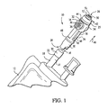
FIG. 1 is a fragmentary exploded perspective view of an I.V. container and a connector not according to the present invention; -
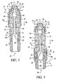
FIG. 2 is a vertical sectional view of the connector ofFIG. 1 in an unlocked position and shown connected to a tubular member of the I.V. container; -
FIG. 3 is a section view of the connector ofFIG. 2 shown in a locked position and connected to the tubular member; -
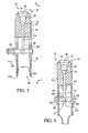
FIG. 4 is an exploded perspective view of an embodiment of the present invention; -
FIG. 5 is a vertical cross-section of the connector ofFIG. 4 ; -
FIG. 6 is a cross-section view taken along lines 6-6 ofFIG. 5 and in the direction generally indicated; and -
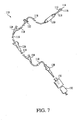
FIG. 7 is a fragmentary exploded view of an administrative set suitable for use with the present connector. - The present connector provides a fluid passageway to a container for improved reconstitution and administration of fluids, including toxic drugs. One feature of the device which includes a connector is that it can be connected to a tubular member of the container that includes an access port, such as an I.V. container, and prevent movement of a body of the connector relative to the tubular member. Such connection offers an advantage in that while the connector is attached to the access port, multiple insertions can be performed with a medical insertion device or fitting, for example a syringe. In preferred embodiments, the locking member is radially repositioned with respect to the fluid passageway of the body to fix the body relative to the access port, and provide a sealed connection. To further illustrate the preferred broader aspects of the invention, a comparative connector and a preferred embodiment of the invention that includes additional inventive features will now be discussed with reference to the drawings.
- Turning now to
FIG. 1 , a comparative connector is generally designated 10, and is intended for use in establishing a positive sealed connection with an administration set or a container, such as an I.V.container 12. A generallytubular member 14 of the I.V.container 12 forms an access port, generally designated 16. Theaccess port 16 is configured for allowing a fluid to flow therethrough and into the I.V.container 12. Preferably, thetubular member 14 includes a firstcylindrical portion 18 and a secondcylindrical portion 20, wherein the second cylindrical portion has a greater diameter relative to the first cylindrical portion to define ashoulder 22 therebetween. Theconnector 10 transfers a fluid, such as cytotoxic or other drugs, from a fluid source (not shown) to theaccess port 16 of the I.V.container 12 via abody 24 of the connector. - The
body 24 is formed in a generally cylindrical shape and includes afluid receiving portion 25 at afirst end 26 that is configured for receiving the fluid source. Opposite thefirst end 26, the body has asecond end 28 configured for engaging theaccess port 16 of the I.V.container 12. While shown as cylindrical, thebody 24 may be provided in other shapes, including having polygonal sides and/or being curved or angled between theends second end 28 is dimensioned to provide a friction fit between alower portion 30 of theconnector 10 and the secondcylindrical portion 20 of the I.V.container 12. - A locking
member 32 is associated with thebody 24 and prevents movement of the body, and in particular movement of thelower portion 30 relative to theaccess port 16 or theshoulder 22 of the I.V.container 12 upon a complete or full insertion of thetubular member 14 into thebody 24. The lockingmember 32 is configured for sliding relative to thebody 24 between unlocked and locked positions. The lockingmember 32 is cylindrically shaped and is formed to have a diameter greater than that of the body to facilitate the sliding engagement. However, the shape of the lockingmember 32 is not critical as long as sliding action relative to thebody 24 is obtained. Preferably, the lockingmember 32 includes a pair ofgripping surfaces 34 that are inwardly or concavely-shaped towards thebody 24 for assisting the user in sliding the locking member. The gripping surfaces may includeoptional dimples 36 for facilitating gripping action by a user, such as a health care worker. - The
body 24 further includes anouter surface 38 that is formed with a plurality ofaxial ridges 40 that are preferably used to align the lockingmember 32 during the sliding movement along the outer surface. A female luer andcap assembly 42 is connected to thebody 24 and forms aradially projecting rim 44 that limits upward sliding axial movement of the lockingmember 32 in a direction of an arrow 46. Similarly, a stop, for example anannular ridge 48 or the like, limits downward movement of the lockingmember 32 in a reverse direction to the arrow 46. Thebody 24 also includes aseptum 50, which is attached to the body by the female luer andcap assembly 42. As is known in the art, theseptum 50 enables a male luer or fluid injecting device, for example a syringe (not shown), to be inserted into thebody 24 to inject fluid therein. Another example is a male luer tip of an administration set (FIG. 7 ) for connecting the I.V.container 12 to a patient. - Referring now to
FIG. 2 , preferably anend 51 of theseptum 50 is formed as a generally flat surface to allow for the end to be readily wiped by a health care worker to promote sterility. The septum also includesthreads 52 that may connect to a male luer lock of an administration set (not shown) and prevent inadvertent disconnection of the administration set. Moreover, the male luer lock connection of the administration set can be attached to theend 51 after a formulation has been made so that exposure of the formulation to a health care worker is minimized. - In
FIG. 2 , theconnector 10 is shown in an unlocked position, in which the lockingmember 32 is adjacent aluer cap 53. Theluer cap 53 encloses afemale luer 54 of theassembly 42, and substantially encloses theseptum 50. At least one tactile indicator or radially projecting formation, such as projectingformations outer surface 38 of thebody 24 to facilitate the positing of the lockingmember 32. Theformations formations member 32 in a locked or unlocked position, and provide an indication to a user of the locked or unlocked status. In addition to indicating locking status, the annular projectingformations member 32 to prevent undesired sliding movement, such as in an axial direction of anarrow 58, or the reverse direction depending on the position of the locking member. - The
connector 10 also includes an internal fluid passageway, generally designated 60 between theends body 24. Thefluid passageway 60 includes a first radialinner chamber 62 adjacent theseptum 50 that feeds fluid into to a second radialinner chamber 64. In turn, thesecond chamber 64 may feed the fluid to a piercing member, such as aneedle 66, which is at least partially enclosed by thebody 24 of thecontainer 10. To prevent potential needle-stick injury it is preferred that apointed end 65 of theneedle 66 is contained well within thebody 24. Thefluid passageway 60 is formed such that theneedle 66 pierces theaccess port 16, which then enables fluid flow through theaccess port 16 and into the I.V.container 12 or another end source. In addition, a threadedannular locking collar 116, such as the threadedannular locking collar 116 partially shown inFIG. 2 and fully illustrated inFIG. 7 , can be connected to thethreads 52 to enable connection of an administration set to theconnector 10. - One feature of the
connector 10 is that multiple accesses to theseptum 50 to inject multiple fluids are possible. That is, theconnector 10 may be used during reconstitution of a drug vial with a pre-assembled luer connection (e.g., Biodome injection), for complete needleless reconstitution and for single dose and multi dose additions. Moreover, the I.V.container 12 with the attachedconnector 10 may be used as a pooled concentrate to multi dose from the I.V. container to one or more additional I.V. containers. - In operation, a male luer (e.g., a syringe), blunt cannula or other preferably needle-free medication delivery device is inserted through an opening or a
slit 68 of theseptum 50 which is depressed to transfer fluid from the male luer to theinternal chambers internal chamber 64 by a funnel-shapedportion 70 of theinternal chamber 64 to theneedle 66, which transfers the fluid in the direction of thearrow 58 to thetubular member 14 and the I.V.container 12. - Referring now to
FIG. 3 , theconnector 10 is shown in a locked position, with the lockingmember 32 displaced in the direction of thearrow 58 and seated at thelower end 28 of thebody 24. In the locked position, the lockingmember 32 engages theradially projecting formation 56b. In addition, the lockingmember 32 is stopped from further movement in the direction of thearrow 48 by theannular ridge 48. In operation, the lockingmember 32 slidingly engages thebody 24 and can be moved between the unlocked position illustrated inFIG. 2 and the locked position illustrated inFIG. 3 . The reciprocal sliding movement of the lockingmember 32 is preferably axially aligned with thebody 24. Once locked, thelower portion 30 of theconnector 10 is prevented by the lockingmember 32 from moving radially outwards in the direction ofarrows 72. This ensures that aninner surface 74 of thebody 24, which forms ashoulder 76, engages theshoulder 22 of thetubular member 14 and prevents movement of the body relative to theaccess port 16 and thetubular member 14. That is, when the lockingmember 32 is near theaccess port end 28 of thebody 24, thetubular member 14 is sealingly fixed to theconnector 10 to facilitate fluid flow into a container, such as the I.V.container 12. - The
slit 68 of theseptum 50 may extend axially or be orientated at an angle relative to thearrow 58. In addition, theslit 68 may be curved slightly or helically rotated to promote the sealing of the opening when a male luer is not inserted therethrough. As can be appreciated, when a male luer extends through theslit 68 and within theconnector 10, the size of the connector and its components are constrained within the spacing between theslit 68 and the funnel- shapedportion 70 of theinternal chamber 64. - To minimize any fluid flow restriction, a passageway or
lumen 78 through theneedle 66 may feed into theinner chamber 64 and aninner passageway 80 of thetubular member 14 without any valves or other obstructions to fluid flow. Preferably, theseptum 50 deforms and stretches to facilitate insertion of a male luer through theslit 68. However, theseptum 50 must be configured in size to seal before, during, and after extension of the fluid injecting device through theslit 68 to form a closed fluid path. Theseptum 50 can be formed of an elastic, resilient material that facilitates insertion of a male luer therethrough, with or without lubrication. Also, theseptum 50 may be formed to facilitate insertion of a blunt cannula. - Referring now to
FIG. 4 , a connector of the present invention is generally designated 82. Components common to theconnecter 10 ofFIG. 1 and theconnector 82 are provided with identical reference numerals. Theconnector 82 has aseptum 50 and a luer cap andfemale luer assembly 42. Theassembly 42 includes theluer cap 53 and thefemale luer 54, which connect to abody 84 of theconnector 82. Anopening 86 in thebody 82 engages an access port (not shown) of a container, such as theaccess port 16 of the I.V.container 12 ofFIG. 1 . Also included is theneedle 66 with thepointed end 65 which is positioned within thebody 84 such that thepointed end 65 is enclosed to prevent potential needle-stick injury. - An important distinction between the
connectors member 88 is laterally, rather than axially, engaged in anaperture 90 defined by the body. Furthermore, the formation of theseptum 50 in the present embodiment can include anend 51 that is configured to accept several different types of luer activating connection designs including, but not limited to, a male luer tip and/or a blunt cannula. Preferably, thebody 84 also has grippingmembers 92 provided with at least oneprotrusion 94 for facilitating user gripping of theconnector 82. - The locking
member 88 is preferably dimensioned to be slidingly insertable into theaperture 90 of thebody 84. In one embodiment, the lockingmember 88 can be formed as a C-shapedclip having arms tubular member 14 ofFIG. 1 , upon insertion of the locking member into theaperture 90 to a closed position (Best seen inFIG. 6 ). The lockingmember 88, also preferably includes an optionalgripping surface 98 that facilitates insertion and removal of the locking member from thebody 84. - Referring now to
FIGs. 5 and 6 , theconnector 82 is shown in an unlocked position with the lockingmember 88 moved in a radial direction of anarrow 100. In this position, theend arms member 88 disengage from theshoulder 22 of the I.V.container 12 ofFIG. 1 . The lockingmember 88 is radially moveable relative to thebody 84 between a locked position as illustrated from a different perspective inFIG. 6 , and the unlocked position illustrated inFIG. 5 . Moreover, in the unlocked position, the lockingmember 88 may be moved in a direction of thearrow 100 to completely disengage the locking member from thebody 84 and provide easy disconnection of theconnector 82 from an I.V. container or the like. - The
body 84 has contouredends container 12, which passes through theopening 86. Similar toaxial passageway 60 ofFIG. 2 , thebody 84 has theneedle 66 positioned internally to allow fluid flow through the needle and to the funnel-shapedportion 70 of theinternal chamber 64, which is configured to receive fluid transferred from an external fluid source, such as a male luer or deliver fluid from the I.V.container 12 through an administration set (FIG. 7 ) to an external source. The male luer may be inserted through theslit 68 of theseptum 50 and then pass through the luer cap andfemale luer assembly 42 to inject fluid into theinner chamber 64. Inserted fluid is then directed by the funnel-shapedportion 70 through alumen 104 of theneedle 66. Similar to theconnector 10 ofFIG. 1 , when theconnector 82 is attached to a tubular member of a container, theneedle 66 pierces an access port of the tubular member to enable fluid passing through thelumen 104 to be deposited into the container. Turning now toFIG. 6 , thebody 84 of theconnector 82 has a generallyrectangular portion 104 that prevents outward radial movement of thearms member 88 into thebody 84. - In use, the connector is placed upon the tubular member (e.g., the
tubular member 14 ofFIG. 1 ). Next, the lockingmember 88 is inserted through theaperture 90 ofFIG. 4 to engage thetubular member 14. Upon engagement, aninner surface 106 of thearms tubular member 14 to prevent movement (e.g., radial and axial movement) of the tubular member relative to thebody 84.Protruded portions 104 of thebody 84 further reinforce abutment of thearms tubular member 14 by preventing radial outward movement of the arms. Axial movement is preferably prevented by having anupper surface 108 of the lockingmember 88 engage ashoulder 22 of thetubular member 14 similar to the arrangement depicted inFIG. 2 . - Thus, it will be seen that the
present connector 82 and lockingmember 88 provide improved connectors for transferring fluid from a male luer (or as discussed earlier, a blunt cannula) to a container, such as an I.V. container and also the ability to deliver fluid from the I.V. container to an external source via an administration set, generally designated as 110 inFIG. 7 . Theconnector 82 reduces the risk of needle puncture or contamination when administering cytotoxic fluids to a patient. Moreover, another advantage of the connector, 82 is that while it is attached to an access port multiple leak-free connections and disconnections can be performed with a male luer. - Referring now to
FIG. 7 , the administration set 110 includes amale luer tip 112 that connects to theconnector 10. More particularly, an end portion oraccess port 114 of themale luer tip 112 passes through the end 51 (FIG. 1 ) of theconnector 10 and is prevented from further insertion into theluer cap 53 by the threadedannular locking collar 116 which surrounds the male luer tip and is configured for threadably engaging thethreads 52 of theseptum 50. The fastening of thelocking collar 116 to theseptum 50 prevents fluid leakage by holding themale luer tip 112 in engagement with the septum. Tubing, generally designated as 118, connects various components of theadministrative set 110. These components include adrip chamber 120, acheck valve 122, at least one Y-site 124, aroller clamp 126, and ablunt cannula 128. - The
drip chamber 120 is generally tubular and has an upper end cap (not shown) and a lower end cap (also not shown). The upper end cap includes a formation for establishing a fluid connection with an upstream portion of the administration set 110, and the lower end cap includes a formation for establishing a fluid connection with a downstream portion of the administration set. The upper end cap typically has a drop former (not shown) which is designed to produce droplets of a desired volume of the fluid as the fluid flows through the upper end cap and through thedip chamber 120. Then, by adjusting the fluid flow so that a desired number of droplets pass through thedrip chamber 120 in a certain period of time, a desired rate of volume and administration may be accomplished. - The
check valve 122 generally permits one-way fluid flow through the administration set 110, and blocks fluid flow in a direction toward thedrip chamber 120. The Y-sites 124 can be used to attach a secondary administration set (not shown) to the administration set 110 and combine two fluids. Theroller clamp 126 controls fluid flow (i.e., start or stop) through the administration set 110. - The
blunt cannula 128 creates a fluid flow path through aninjection site 130 which connects to acatheter 132. Commonly, thecatheter 132 is inserted into a vein of a patient to allow fluid communication with the administration set 110. Thus, the administration set 110 can be considered as a fluid conduit that provides a fluid to theconnector 10, and vice-versa. For example, theconnector 10 can be accessed by themale luer tip 112 of the administration set 110 to allow spike or needle-free access to a container, such as the I.V.container 12, and provide a secure locked connection and delivery of a fluid to and from a patient. - While particular embodiments of the connector have in shown and described, it will be appreciated by those skilled in the art that changes and modifications may be made there too without departing from the invention and its broader aspects and as set forth in the following claims.
Claims (14)
- A connector (82) for facilitating fluid transfer between a needle-free fluid delivery device and a container (12) having an access port (16) comprising:a body (84) having a first end (42) provided with a septum (50) that is configured for receiving the needle-free fluid delivery device and a second end (86, 102a, 102b) for receiving the access port of the container, said body defining a fluid passageway between said first and second ends; anda piercing member (66) in communication with said fluid passageway for transferring fluid passed into said body (84) to the access port (16), and wherein said piercing member is at least partially enclosed by said body (84) to prevent potential injury; characterised in that the connector (82) further comprises a locking member (88) associated with said body (84) that is radially slideable with respect to the body (84) between a first or unlocked position and a second or locked position when the locking member engages the access port (16) to prevent movement of said body (84) relative to the access port (16).
- The connector of claim 1, wherein said first end (42) and septum (50) are configured to sealingly receive a male luer tip.
- The connector of claim 1, wherein said first end (42) and septum (50) are configured to sealingly receive a blunt cannula.
- The connector of any one of claims 1 to 3 further comprising a luer cap (53) attached to said body (84) and configured for sealing said first end (42).
- The connector of any one of claims 1 to 4, wherein said piercing member (66) is a needle having a lumen therethrough.
- The connector of claim 5, wherein said needle (66) has a pointed end (65) enclosed by said body (84).
- The connector of any one of claims 1 to 6, wherein the second end (86, 102a, 102b) of said body is configured to receive a generally tubular member (14) having a shoulder separating different radial portions of the tubular member, and wherein the locking member (88) is configured to be mateable with the tubular member in said second locked position to prevent movement of said second end relative to the shoulder of the tubular member.
- The connector of any one of claims 1 to 7, wherein said body (84) includes an aperture (90) for insertion of said locking member (88).
- The connector of any one of claims 1 to 8, wherein the locking member (88) can be completely disengaged from the body (84).
- The connector of claim 8, wherein said locking member (88) is a C-shaped clip configured for mating engagement with said aperture (90).
- The connector of any one of claims 1 to 10 configured for multiple insertions of the needle-free fluid delivery device into septum (50).
- The connector of any one of claims 1 to 11, wherein the septum (50) includes a slit (68).
- The connector of claim 12, wherein the septum (50) is configured to seal before, during and after extension of the fluid delivery device through the slit (68).
- A method of facilitating fluid communication between a sealed container having an access port (16) and a needle-free fluid delivery device comprising:providing a connector (82) according to any one of claims 1 to 13;attaching the second end of the body (84) to the access port (16) of the container;moving the locking member (88) to the second locked position; andinserting the needle-free fluid delivery device through said septum (50).
Priority Applications (2)
| Application Number | Priority Date | Filing Date | Title |
|---|---|---|---|
| PL04253335T PL1484082T3 (en) | 2003-06-06 | 2004-06-04 | Method and device for transferring fluid |
| EP10075044A EP2189179A1 (en) | 2003-06-06 | 2004-06-04 | Method and device for transferring fluid |
Applications Claiming Priority (2)
| Application Number | Priority Date | Filing Date | Title |
|---|---|---|---|
| US10/457,332 US7025389B2 (en) | 2003-06-06 | 2003-06-06 | Method and device for transferring fluid |
| US457332 | 2003-06-06 |
Related Child Applications (1)
| Application Number | Title | Priority Date | Filing Date |
|---|---|---|---|
| EP10075044.7 Division-Into | 2010-01-29 |
Publications (3)
| Publication Number | Publication Date |
|---|---|
| EP1484082A2 EP1484082A2 (en) | 2004-12-08 |
| EP1484082A3 EP1484082A3 (en) | 2004-12-29 |
| EP1484082B1 true EP1484082B1 (en) | 2010-04-14 |
Family
ID=33159598
Family Applications (2)
| Application Number | Title | Priority Date | Filing Date |
|---|---|---|---|
| EP10075044A Withdrawn EP2189179A1 (en) | 2003-06-06 | 2004-06-04 | Method and device for transferring fluid |
| EP04253335A Expired - Lifetime EP1484082B1 (en) | 2003-06-06 | 2004-06-04 | Method and device for transferring fluid |
Family Applications Before (1)
| Application Number | Title | Priority Date | Filing Date |
|---|---|---|---|
| EP10075044A Withdrawn EP2189179A1 (en) | 2003-06-06 | 2004-06-04 | Method and device for transferring fluid |
Country Status (7)
| Country | Link |
|---|---|
| US (1) | US7025389B2 (en) |
| EP (2) | EP2189179A1 (en) |
| AT (1) | ATE464087T1 (en) |
| DE (1) | DE602004026506D1 (en) |
| DK (1) | DK1484082T3 (en) |
| ES (1) | ES2344061T3 (en) |
| PL (1) | PL1484082T3 (en) |
Families Citing this family (30)
| Publication number | Priority date | Publication date | Assignee | Title |
|---|---|---|---|---|
| US20080009822A1 (en) * | 2003-12-18 | 2008-01-10 | Halkey-Roberts Corporation | Needleless access vial |
| US20070202186A1 (en) | 2006-02-22 | 2007-08-30 | Iscience Interventional Corporation | Apparatus and formulations for suprachoroidal drug delivery |
| CA2834152C (en) | 2006-05-25 | 2016-07-05 | Bayer Healthcare Llc | Reconstitution device |
| US7981090B2 (en) | 2006-10-18 | 2011-07-19 | Baxter International Inc. | Luer activated device |
| US8221363B2 (en) | 2006-10-18 | 2012-07-17 | Baxter Healthcare S.A. | Luer activated device with valve element under tension |
| US7753338B2 (en) | 2006-10-23 | 2010-07-13 | Baxter International Inc. | Luer activated device with minimal fluid displacement |
| ITPD20060419A1 (en) * | 2006-11-13 | 2008-05-14 | Federico Nalesso | DEVICE FOR THE MAINTENANCE TREATMENT OF CENTRAL VENOUS CATHETERS |
| US7637889B2 (en) * | 2006-11-15 | 2009-12-29 | Glynntech, Inc. | Drug delivery device with sliding valve and methodology |
| US8597237B2 (en) * | 2007-05-18 | 2013-12-03 | Carefusion 303, Inc. | Universal needlefree bag access device |
| US8443824B2 (en) * | 2007-10-09 | 2013-05-21 | Fenwal, Inc. | Fluid flow controller |
| AU2009203557B2 (en) * | 2008-01-09 | 2014-02-20 | Novartis Ag | Unitary withdrawal spike unit suitable for factory fitting |
| CA2873003C (en) | 2008-05-14 | 2017-06-13 | J&J Solutions, Inc. | Systems and methods for safe medicament transport |
| US8172823B2 (en) * | 2008-07-03 | 2012-05-08 | Baxter International Inc. | Port assembly for use with needleless connector |
| US7905873B2 (en) * | 2008-07-03 | 2011-03-15 | Baxter International Inc. | Port assembly for use with needleless connector |
| US8062280B2 (en) * | 2008-08-19 | 2011-11-22 | Baxter Healthcare S.A. | Port assembly for use with needleless connector |
| US8864725B2 (en) | 2009-03-17 | 2014-10-21 | Baxter Corporation Englewood | Hazardous drug handling system, apparatus and method |
| CN102428308B (en) | 2009-03-22 | 2014-12-31 | 爱康医学农业合作协会有限公司 | Closed male luer connector |
| US8628509B2 (en) * | 2009-05-11 | 2014-01-14 | Abbott Laboratories | Enteral connectors and systems |
| US8394080B2 (en) * | 2009-05-14 | 2013-03-12 | Baxter International Inc. | Needleless connector with slider |
| EP2959877B2 (en) * | 2010-05-27 | 2020-11-25 | J&J Solutions, Inc. | Closed fluid transfer system |
| US20120271272A1 (en) | 2010-10-15 | 2012-10-25 | Iscience Interventional Corporation | Device for ocular access |
| EP2774650A1 (en) * | 2013-03-04 | 2014-09-10 | Debiotech S.A. | Cap connector assembly |
| US9539139B2 (en) | 2013-05-03 | 2017-01-10 | Clearside Biomedical, Inc. | Apparatus and methods for ocular injection |
| EP3027162B1 (en) | 2013-08-02 | 2018-07-18 | J&J Solutions, Inc. D.B.A Corvida Medical | Compounding systems and methods for safe medicament transport |
| CN104127932B (en) * | 2014-04-18 | 2017-01-11 | 广东海恺普新型医药包装材料有限公司 | Intravenous therapeutic device comprising at least one filter |
| MX2017016684A (en) | 2015-06-19 | 2018-06-11 | Baxalta Inc | Pooling device for single or multiple containers. |
| US10888496B2 (en) | 2015-09-17 | 2021-01-12 | Corvida Medical, Inc. | Medicament vial assembly |
| JP2018530396A (en) | 2015-10-13 | 2018-10-18 | ジェイ アンド ジェイ ソリューションズ,インコーポレイテッド | Automatic compounding equipment for closed fluid transfer systems. |
| WO2018024092A1 (en) * | 2016-08-03 | 2018-02-08 | 山东新华安得医疗用品有限公司 | Closed fluid transfer device and closed fluid transfer method |
| MX2021003919A (en) | 2018-10-03 | 2022-01-18 | Takeda Pharmaceuticals Co | Packaging for multiple containers. |
Family Cites Families (19)
| Publication number | Priority date | Publication date | Assignee | Title |
|---|---|---|---|---|
| NL8300386A (en) * | 1983-02-02 | 1984-09-03 | Steritech Bv | STERILE DEVICE CONNECTING TWO ROOMS. |
| US4792163A (en) * | 1987-05-13 | 1988-12-20 | Baxter Travenol Laboratories, Inc. | Secondary lock for medical tube coupling |
| US4895570A (en) * | 1987-06-05 | 1990-01-23 | Abbott Laboratories | Locking port shroud for peritoneal dialysis tubing connector |
| US4973328A (en) * | 1989-11-20 | 1990-11-27 | Gerard Smith | Closed system administering assembly |
| US5122123A (en) * | 1991-01-30 | 1992-06-16 | Vaillancourt Vincent L | Closed system connector assembly |
| US5405333A (en) * | 1992-12-28 | 1995-04-11 | Richmond; Frank M. | Liquid medicament bag with needleless connector fitting using boat assembly |
| WO1994023775A1 (en) * | 1993-03-23 | 1994-10-27 | Abbott Laboratories | Securing collar for cannula connector |
| US5423775A (en) * | 1994-01-21 | 1995-06-13 | Winfield Industries | Locking connector assembly |
| US5513882A (en) * | 1994-09-30 | 1996-05-07 | Lewis; Phil | Universal non-threaded pipe connector system |
| US5562616A (en) * | 1995-03-01 | 1996-10-08 | Habley Medical Technology Corporation | Semi-automatic reconstituting system for binary oncolytic pharmaceuticals |
| US5566729A (en) * | 1995-04-06 | 1996-10-22 | Abbott Laboratories | Drug reconstitution and administration system |
| SE509950C2 (en) * | 1995-05-02 | 1999-03-29 | Carmel Pharma Ab | Device for the administration of toxic liquid |
| US5839715A (en) * | 1995-05-16 | 1998-11-24 | Alaris Medical Systems, Inc. | Medical adapter having needleless valve and sharpened cannula |
| US5775671A (en) * | 1996-06-13 | 1998-07-07 | Nypro Inc. | Luer-activated valve |
| WO1998052631A1 (en) * | 1997-05-20 | 1998-11-26 | Baxter International, Inc. | Needleless connector |
| US6036171A (en) * | 1997-09-17 | 2000-03-14 | Halkey-Roberts Corporation | Swabbable valve assembly |
| US6071270A (en) * | 1997-12-04 | 2000-06-06 | Baxter International Inc. | Sliding reconstitution device with seal |
| US6210359B1 (en) * | 2000-01-21 | 2001-04-03 | Jet Medica, L.L.C. | Needleless syringe |
| SE519037C2 (en) * | 2001-01-24 | 2002-12-23 | Carmel Pharma Ab | Infusion bag and infusion system |
-
2003
- 2003-06-06 US US10/457,332 patent/US7025389B2/en not_active Expired - Fee Related
-
2004
- 2004-06-04 EP EP10075044A patent/EP2189179A1/en not_active Withdrawn
- 2004-06-04 DE DE602004026506T patent/DE602004026506D1/en not_active Expired - Lifetime
- 2004-06-04 ES ES04253335T patent/ES2344061T3/en not_active Expired - Lifetime
- 2004-06-04 EP EP04253335A patent/EP1484082B1/en not_active Expired - Lifetime
- 2004-06-04 PL PL04253335T patent/PL1484082T3/en unknown
- 2004-06-04 AT AT04253335T patent/ATE464087T1/en active
- 2004-06-04 DK DK04253335.6T patent/DK1484082T3/en active
Also Published As
| Publication number | Publication date |
|---|---|
| PL1484082T3 (en) | 2010-09-30 |
| US20040260266A1 (en) | 2004-12-23 |
| EP1484082A2 (en) | 2004-12-08 |
| EP2189179A1 (en) | 2010-05-26 |
| ES2344061T3 (en) | 2010-08-17 |
| DK1484082T3 (en) | 2010-07-12 |
| DE602004026506D1 (en) | 2010-05-27 |
| US7025389B2 (en) | 2006-04-11 |
| ATE464087T1 (en) | 2010-04-15 |
| EP1484082A3 (en) | 2004-12-29 |
Similar Documents
| Publication | Publication Date | Title |
|---|---|---|
| EP1484082B1 (en) | Method and device for transferring fluid | |
| EP1957028B1 (en) | Needleless additive control valve | |
| US6146362A (en) | Needleless IV medical delivery system | |
| CA2267581C (en) | Self-priming needle-free "y"-adapter | |
| US8062280B2 (en) | Port assembly for use with needleless connector | |
| US5833674A (en) | Needleless IV medical delivery system | |
| US6595964B2 (en) | Luer activated thread coupler | |
| US5242423A (en) | Needleless syringe | |
| US8864725B2 (en) | Hazardous drug handling system, apparatus and method | |
| AU765829B2 (en) | Swabbable needleless low reflux injection port system | |
| US9352138B2 (en) | Pre-pierced IV access port | |
| US20060089604A1 (en) | Infusion device for administering fluids to a patient | |
| US5533993A (en) | Medication injector with protected cannula and Y-site lockout | |
| US20060058741A1 (en) | Infusion apparatus for infusion bags | |
| WO1995005863A1 (en) | Needleless iv medical delivery system | |
| AU683226B2 (en) | Needleless IV medical delivery system | |
| CA2170237A1 (en) | Needleless iv medical delivery system | |
| AU635736B2 (en) | Pre-slit injection site and tapered cannula | |
| JPH03133456A (en) | Device for storing, preparing and using drug | |
| CA2169708A1 (en) | Medication injector with protected cannula and y-site lockout |
Legal Events
| Date | Code | Title | Description |
|---|---|---|---|
| PUAI | Public reference made under article 153(3) epc to a published international application that has entered the european phase |
Free format text: ORIGINAL CODE: 0009012 |
|
| PUAL | Search report despatched |
Free format text: ORIGINAL CODE: 0009013 |
|
| 17P | Request for examination filed |
Effective date: 20040619 |
|
| AK | Designated contracting states |
Kind code of ref document: A2 Designated state(s): AT BE BG CH CY CZ DE DK EE ES FI FR GB GR HU IE IT LI LU MC NL PL PT RO SE SI SK TR |
|
| AX | Request for extension of the european patent |
Extension state: AL HR LT LV MK |
|
| AK | Designated contracting states |
Kind code of ref document: A3 Designated state(s): AT BE BG CH CY CZ DE DK EE ES FI FR GB GR HU IE IT LI LU MC NL PL PT RO SE SI SK TR |
|
| AX | Request for extension of the european patent |
Extension state: AL HR LT LV MK |
|
| RIC1 | Information provided on ipc code assigned before grant |
Ipc: 7A 61M 39/04 B Ipc: 7A 61J 1/00 B Ipc: 7F 16L 37/14 B Ipc: 7A 61M 39/10 A |
|
| AKX | Designation fees paid |
Designated state(s): AT BE BG CH CY CZ DE DK EE ES FI FR GB GR HU IE IT LI LU MC NL PL PT RO SE SI SK TR |
|
| GRAP | Despatch of communication of intention to grant a patent |
Free format text: ORIGINAL CODE: EPIDOSNIGR1 |
|
| GRAS | Grant fee paid |
Free format text: ORIGINAL CODE: EPIDOSNIGR3 |
|
| GRAA | (expected) grant |
Free format text: ORIGINAL CODE: 0009210 |
|
| AK | Designated contracting states |
Kind code of ref document: B1 Designated state(s): AT BE BG CH CY CZ DE DK EE ES FI FR GB GR HU IE IT LI LU MC NL PL PT RO SE SI SK TR |
|
| REG | Reference to a national code |
Ref country code: GB Ref legal event code: FG4D |
|
| REG | Reference to a national code |
Ref country code: CH Ref legal event code: EP |
|
| REG | Reference to a national code |
Ref country code: IE Ref legal event code: FG4D |
|
| REG | Reference to a national code |
Ref country code: CH Ref legal event code: NV Representative=s name: KIRKER & CIE S.A. |
|
| REF | Corresponds to: |
Ref document number: 602004026506 Country of ref document: DE Date of ref document: 20100527 Kind code of ref document: P |
|
| REG | Reference to a national code |
Ref country code: NL Ref legal event code: T3 |
|
| REG | Reference to a national code |
Ref country code: DK Ref legal event code: T3 |
|
| PGFP | Annual fee paid to national office [announced via postgrant information from national office to epo] |
Ref country code: DK Payment date: 20100625 Year of fee payment: 7 |
|
| REG | Reference to a national code |
Ref country code: ES Ref legal event code: FG2A Ref document number: 2344061 Country of ref document: ES Kind code of ref document: T3 |
|
| REG | Reference to a national code |
Ref country code: PL Ref legal event code: T3 |
|
| PG25 | Lapsed in a contracting state [announced via postgrant information from national office to epo] |
Ref country code: SE Free format text: LAPSE BECAUSE OF FAILURE TO SUBMIT A TRANSLATION OF THE DESCRIPTION OR TO PAY THE FEE WITHIN THE PRESCRIBED TIME-LIMIT Effective date: 20100414 |
|
| PGFP | Annual fee paid to national office [announced via postgrant information from national office to epo] |
Ref country code: BE Payment date: 20100630 Year of fee payment: 7 Ref country code: NL Payment date: 20100624 Year of fee payment: 7 |
|
| PG25 | Lapsed in a contracting state [announced via postgrant information from national office to epo] |
Ref country code: SI Free format text: LAPSE BECAUSE OF FAILURE TO SUBMIT A TRANSLATION OF THE DESCRIPTION OR TO PAY THE FEE WITHIN THE PRESCRIBED TIME-LIMIT Effective date: 20100414 Ref country code: FI Free format text: LAPSE BECAUSE OF FAILURE TO SUBMIT A TRANSLATION OF THE DESCRIPTION OR TO PAY THE FEE WITHIN THE PRESCRIBED TIME-LIMIT Effective date: 20100414 |
|
| PGFP | Annual fee paid to national office [announced via postgrant information from national office to epo] |
Ref country code: CZ Payment date: 20100518 Year of fee payment: 7 Ref country code: IT Payment date: 20100624 Year of fee payment: 7 |
|
| PG25 | Lapsed in a contracting state [announced via postgrant information from national office to epo] |
Ref country code: GR Free format text: LAPSE BECAUSE OF FAILURE TO SUBMIT A TRANSLATION OF THE DESCRIPTION OR TO PAY THE FEE WITHIN THE PRESCRIBED TIME-LIMIT Effective date: 20100715 Ref country code: CY Free format text: LAPSE BECAUSE OF FAILURE TO SUBMIT A TRANSLATION OF THE DESCRIPTION OR TO PAY THE FEE WITHIN THE PRESCRIBED TIME-LIMIT Effective date: 20100414 |
|
| PGFP | Annual fee paid to national office [announced via postgrant information from national office to epo] |
Ref country code: PL Payment date: 20100519 Year of fee payment: 7 |
|
| PG25 | Lapsed in a contracting state [announced via postgrant information from national office to epo] |
Ref country code: PT Free format text: LAPSE BECAUSE OF FAILURE TO SUBMIT A TRANSLATION OF THE DESCRIPTION OR TO PAY THE FEE WITHIN THE PRESCRIBED TIME-LIMIT Effective date: 20100816 Ref country code: EE Free format text: LAPSE BECAUSE OF FAILURE TO SUBMIT A TRANSLATION OF THE DESCRIPTION OR TO PAY THE FEE WITHIN THE PRESCRIBED TIME-LIMIT Effective date: 20100414 Ref country code: MC Free format text: LAPSE BECAUSE OF NON-PAYMENT OF DUE FEES Effective date: 20100630 |
|
| PLBE | No opposition filed within time limit |
Free format text: ORIGINAL CODE: 0009261 |
|
| STAA | Information on the status of an ep patent application or granted ep patent |
Free format text: STATUS: NO OPPOSITION FILED WITHIN TIME LIMIT |
|
| PG25 | Lapsed in a contracting state [announced via postgrant information from national office to epo] |
Ref country code: SK Free format text: LAPSE BECAUSE OF FAILURE TO SUBMIT A TRANSLATION OF THE DESCRIPTION OR TO PAY THE FEE WITHIN THE PRESCRIBED TIME-LIMIT Effective date: 20100414 Ref country code: RO Free format text: LAPSE BECAUSE OF FAILURE TO SUBMIT A TRANSLATION OF THE DESCRIPTION OR TO PAY THE FEE WITHIN THE PRESCRIBED TIME-LIMIT Effective date: 20100414 |
|
| 26N | No opposition filed |
Effective date: 20110117 |
|
| PGFP | Annual fee paid to national office [announced via postgrant information from national office to epo] |
Ref country code: CH Payment date: 20110627 Year of fee payment: 8 Ref country code: ES Payment date: 20110628 Year of fee payment: 8 |
|
| BERE | Be: lapsed |
Owner name: BAXTER INTERNATIONAL INC. Effective date: 20110630 |
|
| REG | Reference to a national code |
Ref country code: NL Ref legal event code: V1 Effective date: 20120101 |
|
| PG25 | Lapsed in a contracting state [announced via postgrant information from national office to epo] |
Ref country code: CZ Free format text: LAPSE BECAUSE OF NON-PAYMENT OF DUE FEES Effective date: 20110604 |
|
| REG | Reference to a national code |
Ref country code: DK Ref legal event code: EBP |
|
| PG25 | Lapsed in a contracting state [announced via postgrant information from national office to epo] |
Ref country code: IT Free format text: LAPSE BECAUSE OF NON-PAYMENT OF DUE FEES Effective date: 20110604 |
|
| PG25 | Lapsed in a contracting state [announced via postgrant information from national office to epo] |
Ref country code: BE Free format text: LAPSE BECAUSE OF NON-PAYMENT OF DUE FEES Effective date: 20110630 |
|
| PG25 | Lapsed in a contracting state [announced via postgrant information from national office to epo] |
Ref country code: NL Free format text: LAPSE BECAUSE OF NON-PAYMENT OF DUE FEES Effective date: 20120101 |
|
| PG25 | Lapsed in a contracting state [announced via postgrant information from national office to epo] |
Ref country code: DK Free format text: LAPSE BECAUSE OF NON-PAYMENT OF DUE FEES Effective date: 20110630 |
|
| PG25 | Lapsed in a contracting state [announced via postgrant information from national office to epo] |
Ref country code: HU Free format text: LAPSE BECAUSE OF FAILURE TO SUBMIT A TRANSLATION OF THE DESCRIPTION OR TO PAY THE FEE WITHIN THE PRESCRIBED TIME-LIMIT Effective date: 20101015 Ref country code: BG Free format text: LAPSE BECAUSE OF FAILURE TO SUBMIT A TRANSLATION OF THE DESCRIPTION OR TO PAY THE FEE WITHIN THE PRESCRIBED TIME-LIMIT Effective date: 20100414 Ref country code: LU Free format text: LAPSE BECAUSE OF NON-PAYMENT OF DUE FEES Effective date: 20100604 |
|
| PG25 | Lapsed in a contracting state [announced via postgrant information from national office to epo] |
Ref country code: PL Free format text: LAPSE BECAUSE OF NON-PAYMENT OF DUE FEES Effective date: 20110604 Ref country code: TR Free format text: LAPSE BECAUSE OF FAILURE TO SUBMIT A TRANSLATION OF THE DESCRIPTION OR TO PAY THE FEE WITHIN THE PRESCRIBED TIME-LIMIT Effective date: 20100414 |
|
| REG | Reference to a national code |
Ref country code: PL Ref legal event code: LAPE |
|
| REG | Reference to a national code |
Ref country code: CH Ref legal event code: PL |
|
| REG | Reference to a national code |
Ref country code: CH Ref legal event code: PL |
|
| PG25 | Lapsed in a contracting state [announced via postgrant information from national office to epo] |
Ref country code: CH Free format text: LAPSE BECAUSE OF NON-PAYMENT OF DUE FEES Effective date: 20120630 Ref country code: LI Free format text: LAPSE BECAUSE OF NON-PAYMENT OF DUE FEES Effective date: 20120630 |
|
| PG25 | Lapsed in a contracting state [announced via postgrant information from national office to epo] |
Ref country code: BG Free format text: LAPSE BECAUSE OF FAILURE TO SUBMIT A TRANSLATION OF THE DESCRIPTION OR TO PAY THE FEE WITHIN THE PRESCRIBED TIME-LIMIT Effective date: 20100714 |
|
| REG | Reference to a national code |
Ref country code: ES Ref legal event code: FD2A Effective date: 20131021 |
|
| PG25 | Lapsed in a contracting state [announced via postgrant information from national office to epo] |
Ref country code: ES Free format text: LAPSE BECAUSE OF NON-PAYMENT OF DUE FEES Effective date: 20120605 |
|
| PGFP | Annual fee paid to national office [announced via postgrant information from national office to epo] |
Ref country code: IE Payment date: 20140627 Year of fee payment: 11 Ref country code: GB Payment date: 20140627 Year of fee payment: 11 |
|
| PGFP | Annual fee paid to national office [announced via postgrant information from national office to epo] |
Ref country code: AT Payment date: 20140521 Year of fee payment: 11 |
|
| PGFP | Annual fee paid to national office [announced via postgrant information from national office to epo] |
Ref country code: DE Payment date: 20140627 Year of fee payment: 11 |
|
| PGFP | Annual fee paid to national office [announced via postgrant information from national office to epo] |
Ref country code: FR Payment date: 20140617 Year of fee payment: 11 |
|
| REG | Reference to a national code |
Ref country code: DE Ref legal event code: R119 Ref document number: 602004026506 Country of ref document: DE |
|
| REG | Reference to a national code |
Ref country code: AT Ref legal event code: MM01 Ref document number: 464087 Country of ref document: AT Kind code of ref document: T Effective date: 20150604 |
|
| GBPC | Gb: european patent ceased through non-payment of renewal fee |
Effective date: 20150604 |
|
| REG | Reference to a national code |
Ref country code: IE Ref legal event code: MM4A |
|
| REG | Reference to a national code |
Ref country code: FR Ref legal event code: ST Effective date: 20160229 |
|
| PG25 | Lapsed in a contracting state [announced via postgrant information from national office to epo] |
Ref country code: DE Free format text: LAPSE BECAUSE OF NON-PAYMENT OF DUE FEES Effective date: 20160101 Ref country code: IE Free format text: LAPSE BECAUSE OF NON-PAYMENT OF DUE FEES Effective date: 20150604 Ref country code: GB Free format text: LAPSE BECAUSE OF NON-PAYMENT OF DUE FEES Effective date: 20150604 |
|
| PG25 | Lapsed in a contracting state [announced via postgrant information from national office to epo] |
Ref country code: FR Free format text: LAPSE BECAUSE OF NON-PAYMENT OF DUE FEES Effective date: 20150630 Ref country code: AT Free format text: LAPSE BECAUSE OF NON-PAYMENT OF DUE FEES Effective date: 20150604 |