EP1483996A1 - Accesoire de travail rotatif pour appareil electromenager de preparation culinaire - Google Patents
Accesoire de travail rotatif pour appareil electromenager de preparation culinaire Download PDFInfo
- Publication number
- EP1483996A1 EP1483996A1 EP04356072A EP04356072A EP1483996A1 EP 1483996 A1 EP1483996 A1 EP 1483996A1 EP 04356072 A EP04356072 A EP 04356072A EP 04356072 A EP04356072 A EP 04356072A EP 1483996 A1 EP1483996 A1 EP 1483996A1
- Authority
- EP
- European Patent Office
- Prior art keywords
- insert
- working
- accessory according
- rotary working
- tool
- Prior art date
- Legal status (The legal status is an assumption and is not a legal conclusion. Google has not performed a legal analysis and makes no representation as to the accuracy of the status listed.)
- Granted
Links
- 235000021478 household food Nutrition 0.000 title claims description 3
- 238000005520 cutting process Methods 0.000 claims description 10
- 238000002360 preparation method Methods 0.000 claims description 5
- 230000002093 peripheral effect Effects 0.000 claims description 4
- 239000002184 metal Substances 0.000 abstract description 8
- 239000000463 material Substances 0.000 abstract description 6
- 238000002347 injection Methods 0.000 abstract description 3
- 239000007924 injection Substances 0.000 abstract description 3
- 230000000903 blocking effect Effects 0.000 description 5
- 238000004140 cleaning Methods 0.000 description 2
- 238000010276 construction Methods 0.000 description 2
- 239000011521 glass Substances 0.000 description 2
- 238000009434 installation Methods 0.000 description 2
- 239000004952 Polyamide Substances 0.000 description 1
- 239000004743 Polypropylene Substances 0.000 description 1
- 239000011324 bead Substances 0.000 description 1
- 230000000295 complement effect Effects 0.000 description 1
- 239000000839 emulsion Substances 0.000 description 1
- 239000000835 fiber Substances 0.000 description 1
- 238000004898 kneading Methods 0.000 description 1
- 238000012423 maintenance Methods 0.000 description 1
- 238000004519 manufacturing process Methods 0.000 description 1
- 238000012986 modification Methods 0.000 description 1
- 230000004048 modification Effects 0.000 description 1
- 229920002647 polyamide Polymers 0.000 description 1
- -1 polypropylene Polymers 0.000 description 1
- 229920001155 polypropylene Polymers 0.000 description 1
- 230000000717 retained effect Effects 0.000 description 1
- 238000006467 substitution reaction Methods 0.000 description 1
Images


Classifications
-
- A—HUMAN NECESSITIES
- A47—FURNITURE; DOMESTIC ARTICLES OR APPLIANCES; COFFEE MILLS; SPICE MILLS; SUCTION CLEANERS IN GENERAL
- A47J—KITCHEN EQUIPMENT; COFFEE MILLS; SPICE MILLS; APPARATUS FOR MAKING BEVERAGES
- A47J43/00—Implements for preparing or holding food, not provided for in other groups of this subclass
- A47J43/04—Machines for domestic use not covered elsewhere, e.g. for grinding, mixing, stirring, kneading, emulsifying, whipping or beating foodstuffs, e.g. power-driven
- A47J43/07—Parts or details, e.g. mixing tools, whipping tools
- A47J43/0705—Parts or details, e.g. mixing tools, whipping tools for machines with tools driven from the upper side
- A47J43/0711—Parts or details, e.g. mixing tools, whipping tools for machines with tools driven from the upper side mixing, whipping or cutting tools
Definitions
- the present invention relates to the general technical field of apparatus kitchen appliances with a work accessory rotary rotating in a working container.
- the present invention relates in particular to mini-choppers comprising a motor housing arranged on the working container.
- the present invention also relates to work receptacles comprising an rotary work driven by a mixer type device.
- the present invention also relates to household robots with a working container having a drive device in the bottom of the working container and a lid closing the working container.
- the present invention relates more particularly to accessories for rotary work.
- the aforementioned rotary working accessories include a hub driven by its upper end.
- the lower end of the hub is intended for the guiding in rotation of the rotary working accessory in the working container.
- Most rotary work accessories have a fixed work tool to the hub. This work tool can have one or more parts metal such as in particular cutting blades.
- Document FR 2 360 285 discloses a rotary working accessory comprising two blades mounted superimposed in a hub.
- the hub includes an upper part provided with an axial pin intended to be driven by the motor shaft, a middle part arranged between the two blades, a lower part, an axial bearing intended to rotate on an axis mounted on the bottom of the working container, and two rivets crossing the blades, designed to assemble the upper part with the lower part.
- the making such an accessory requires a large number of operations assembly.
- Document FR 2 743 710 discloses a rotary working accessory comprising an inclined blade mounted between an upper part and a part lower of a hub.
- the upper part has an axial bearing provided for turn on an axis from a base secured to the hub.
- the assembly of hub is relatively delicate due to the presence of the blade.
- the hub is partially hollow to accommodate balancing weights and to allow a larger diameter of the hub at the blade. This layout complicates assembly operations.
- the object of the present invention is to simplify the construction of an accessory working table for household food preparation appliance.
- Another object of the present invention is to facilitate the cleaning of such a accessory.
- Another object of the present invention is to improve the quality of the preparations made with such an accessory.
- a rotating work attachment for a device kitchen appliance comprising a hub carrying a tool working, the hub having an axial cavity at one end and a member drive at the other end, characterized in that the hub has a insert and an envelope, the axial cavity being formed in the insert, the envelope being overmolded on the insert.
- the working tool is mounted on the insert, the envelope being overmolded on the insert carrying the working tool.
- This arrangement allows the work tool to be prepositioned in the mold during overmolding, and facilitates handling.
- the working tool can be metallic, in particular for make a working tool for cutting and / or grinding.
- the working tool could for example be constituted by flexible wires put in place on the insert before overmolding the envelope.
- the working tool comprises at least one cutting blade.
- the work tool may in particular include a metal rod intended to knead the dough.
- the working tool mounted on the insert rests on a support formed on the periphery of the insert.
- the support could be made in the mold.
- the support is formed by at least a portion of peripheral collar provided on the insert.
- the support can in particular be formed by a series of studs formed on the periphery of the insert.
- the insert comprises at least one blocking member provided for maintain the work tool. This arrangement facilitates handling of the insert and the working tool before their installation in the mold overmolding.
- the blocking members comprise a tab elastic and a stopper.
- Other embodiments can be envisaged, in particular several elastic tabs distributed over the periphery of the insert.
- the axial cavity is arranged between the elastic tab and stop.
- the elastic tab and the stopper are arranged on either side of the axis of rotation of the insert. This provision ensures good maintenance of the work tool.
- the insert has an outer wall in which are formed of lateral cavities. This provision guarantees a minimum thickness for the envelope, which facilitates the connection between the insert and the envelope, and to obtain a better surface finish for the envelope.
- the thickness of the envelope is between 2 and 3 mm. This arrangement makes it possible to obtain a particularly surface appearance. satisfactory, which facilitates cleaning.
- the narrower width of the lateral cavities is between 2 and 3 mm. This arrangement allows good attachment of the envelope in the insert.
- the working tool comprises an annular part provided for be mounted on the insert.
- This arrangement facilitates the production of the job.
- This arrangement also facilitates its positioning on the insert.
- the working tool comes from the envelope.
- This arrangement can be made in substitution or in complement of the embodiment in which the working tool is mounted on the insert.
- This arrangement is particularly suitable for producing fins of mixing.
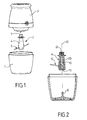
- FIG. 1 A kitchen appliance with an accessory of rotary work 2 according to the present invention is illustrated in FIG. 1.
- the rotary work attachment 2 rotates in a work container 1 and is driven by a drive device 7 arranged in a motor housing 3, not described in detail.
- the rotary working accessory 2 comprises a working tool 5 mounted in a hub 4.
- the working tool 5 is metallic and forms two cutting blades 5a, 5b.
- the hub 4 has an axial cavity 11 in one of its ends and a drive member 21 at the other end.
- the axial cavity 11 and the drive member 21 define an axis of rotation 22.
- the axial cavity 11 is formed at the lower end of the hub 4.
- the cavity axial 11 is provided to rotate on a guide element 8 from the bottom of the working container 1.
- the guide element 8 is a metallic axis.
- the drive member 21 is formed at the upper end of the hub 4.
- the drive member 21 is provided to cooperate with the device drive 7 of the motor housing 3.
- the hub 4 has an insert 10 and an envelope 20.
- the axial cavity 11 is formed in the insert 10.
- the envelope 20 is molded onto the insert 10 bearing the working tool 5.
- the drive member 21 is formed on the envelope 20.
- the envelope 20 is made of a material compatible with an operation rapid injection, such as for example polypropylene loaded with fibers glass.
- the insert 10 is made of a material having a low coefficient of friction and good wear resistance, especially in a material allowing friction on a metal axis up to speeds from 4000 to 8000 rpm. Preferably, this material can be injected or molded.
- the insert 10 is for example made of polyamide reinforced with glass beads.
- a support 12 is formed on the periphery of the insert 10.
- the support 12 is formed by a peripheral flange.
- the support 12 is inclined relative to the axis of rotation 22.
- the insert 10 comprises blocking members 14 provided for holding the working tool 5.
- the locking members 14 include an elastic tab 15 and a stop 16 formed under a rib 17.
- the elastic tab 15, the rib 17 and the stop 16 are arranged above the support 12. More particularly, the flange device forming the support 12 is interrupted under the stop 16.
- the tab elastic 15 and the stop 16 are arranged on either side of the axis of rotation 22.
- the axial cavity 11 is arranged between the elastic tab 15 and the stop 16.
- the elastic tab 15 and the rib 16 are parallel to the axis of rotation 22.
- the insert 10 has an outer wall 18 in which are formed lateral cavities 19.
- the lateral cavities 19 are present above and in below the support 12.
- the smallest width of the lateral cavities 19 is preferably between 2 mm and 3 mm.
- the thickness of the envelope 20 is between 2 and 3 mm at the outer wall 18 outside the side cavities 19.
- the working tool 5 is mounted on the insert 10.
- the working tool 5 has an annular part 6, better visible in FIG. 5, intended to be mounted around the insert 10.
- the two blades 5a, 5b extend on either side of the annular part 6.
- the annular part 6 has two notches, 6a, 6b, intended to be engaged respectively on the elastic tab 15 and on the rib 17.
- the rotary working accessory 2 is produced in the following manner next.
- the working tool 5 is placed on the insert 10.
- the annular part 6 of the working tool 5 rests on the support 12 of the insert 10.
- the elastic tab 15 deformed during the installation of the working tool 5 then makes it possible to block the working tool 5 also retained by the stop 16.
- the insert 10 with the working tool 5 is placed in an injection mold to make the envelope 20 around the insert 10.
- the depth of the lateral cavities 19 allows the envelope 20 to be anchored in the insert 10.
- the rotary working accessory 2 obtained is illustrated in FIG. 6.
- the inclined support 12 makes it possible to use only one blade for carrying out the tool work 5.
- the working tool 5 does not necessarily have two cutting blades 5a, 5b inclined from the same metal part.
- the tool of work can in particular comprise a metal rod for kneading, or flexible son to make emulsions.
- the working tool 5 is not necessarily made in one single piece.
- the working tool can for example comprise two blades superimposed cutting edges each comprising an annular part mounted on the insert.
- the drive device 7 does not belong necessarily to a motor housing, but can for example belong to a cover closing the working container and being driven by a motor housing independent of said cover.
- the support 12 can be formed by one or more portions peripheral flange.
- One or more blocking members 14 can be provided.
- the blocking member (s) 14 are not necessarily arranged between the support 12 and the upper end of the insert 10, but can in particular be arranged between the support 12 and the lower end of the insert 10.
- the guide element 8 does not necessarily come from the bottom of working container 1, but may for example belong to a base movable in rotation relative to the hub, as described for example in the document FR 2 743 710 or document FR 2 768 608.
- the guide element is not necessarily formed by a metal axis, but can for example be formed by the bottom of the working container 1 or by the aforementioned base.
- FIG. 7 illustrates an alternative embodiment differing from the example of previous embodiment in that the working tool 5 'comes from the envelope 20' of the 4 'hub. More particularly, the working tool 5 'has several arms attached to their lower and upper ends to the hub 4 '. The 11 'cavity is provided in the lower end of the insert 10 'covered by the envelope 20 '. The drive member 21 'is formed in the upper end of envelope 20 '.
- the drive member 21, 21 ' is not necessarily formed on the upper end of the hub 4, 4 'and the cavity axial 11, 11 ′ is not necessarily arranged on the lower end of the hub 4, 4 '.
- An axial cavity formed on the upper end of the hub can cooperate with a shaft mounted in a cover closing a container of work, a drive device arranged in the bottom of the working container cooperating with a drive member formed on the lower end of the hub.
- the drive member 21, 21 ' can be from hub 4, 4 '.
Landscapes
- Engineering & Computer Science (AREA)
- Mechanical Engineering (AREA)
- Food Science & Technology (AREA)
- Food-Manufacturing Devices (AREA)
- Adjustable Resistors (AREA)
Abstract
- L'invention concerne un accessoire de travail rotatif pour appareil électroménager de préparation culinaire, comportant un moyeu (4) portant un outil de travail (5), le moyeu (4) présentant une cavité axiale (11) à une extrémité et un organe d'entraínement (21) à l'autre extrémité).
- Conformément à l'invention, le moyeu (4) comporte un insert (10) et une enveloppe (20), la cavité axiale (11) étant ménagée dans l'insert (10), l'enveloppe (20) étant surmoulée sur l'insert (10).
Description
- la figure 1 est une vue d'un appareil électroménager de préparation culinaire comportant un accessoire de travail rotatif selon l'invention,
- la figure 2 est une vue en coupe selon une autre orientation de l'accessoire de travail rotatif et du récipient de travail montré à la figure 1,
- la figure 3 est une vue de l'insert de l'accessoire de travail rotatif montré aux figures 1 et 2,
- la figure 4 est une vue selon une autre orientation de l'insert montré à la figure 3, sur lequel est monté une lame de coupe,
- la figure 5 est une vue selon une autre orientation de l'insert et de la lame de coupe montrés à la figure 4,
- la figure 6 est une vue de l'accessoire de travail rotatif montré aux figures 1 et 2, après surmoulage d'une enveloppe sur l'insert et la lame de coupe montrés aux figures 4 et 5,
- la figure 7 est une vue en perspective et en coupe partielle d'une variante de l'accessoire de travail rotatif illustré aux figures 1 à 6.
Claims (14)
- Accessoire de travail rotatif pour appareil électroménager de préparation culinaire, comportant un moyeu (4 ; 4') portant un outil de travail (5 ; 5'), le moyeu (4 ; 4') présentant une cavité axiale (11 ; 11') à une extrémité et un organe d'entraínement (21 ; 21') à l'autre extrémité, caractérisé en ce que le moyeu (4 ; 4') comporte un insert (10 ; 10') et une enveloppe (20 ; 20'), la cavité axiale (11 ; 11') étant ménagée dans l'insert (10 ; 10'), l'enveloppe (20 ; 20') étant surmoulée sur l'insert (10 ; 10').
- Accessoire de travail rotatif selon la revendication 1, caractérisé en ce que l'outil de travail (5) est monté sur l'insert (10), l'enveloppe (20) étant surmoulée sur l'insert (10) portant l'outil de travail (5).
- Accessoire de travail rotatif selon la revendication 2, caractérisé en ce que l'outil de travail (5) est métallique.
- Accessoire de travail rotatif selon l'une des revendications 2 ou 3, caractérisé en ce que l'outil de travail (5) comporte au moins une lame coupante (5a, 5b).
- Accessoire de travail rotatif selon l'une des revendications 2 à 4, caractérisé en ce que l'outil de travail (5) monté sur l'insert (10) repose sur un support (12) ménagé sur la périphérie de l'insert (10).
- Accessoire de travail rotatif selon la revendication 5, caractérisé en ce que le support (12) est formé par au moins une portion de collerette périphérique ménagée sur l'insert (10).
- Accessoire de travail rotatif selon l'une des revendications 2 à 6, caractérisé en ce que l'insert (10) comporte au moins un organe de blocage (14) prévu pour maintenir l'outil de travail (5).
- Accessoire de travail rotatif selon la revendication 7, caractérisé en ce que les organes de blocage (14) comprennent une patte élastique (15) et une butée (16).
- Accessoire de travail rotatif selon la revendication 8, caractérisé en ce que la cavité axiale (11) est agencée entre la patte élastique (15) et la butée (16).
- Accessoire de travail rotatif selon l'une des revendications 1 à 9, caractérisé en ce que l'insert (10) présente une paroi extérieure (18) dans laquelle sont formées des cavités latérales (19).
- Accessoire de travail rotatif selon la revendication 10, caractérisé en ce que l'épaisseur de l'enveloppe (20) est comprise entre 2 et 3 mm.
- Accessoire de travail rotatif selon l'une des revendications 10 ou 11, caractérisé en ce que la plus faible largeur des cavités latérales (19) est comprise entre 2 et 3 mm.
- Accessoire de travail rotatif selon l'une des revendications 2 à 12, caractérisé en ce que l'outil de travail (5) comporte une partie annulaire (6) prévue pour être montée sur l'insert (10).
- Accessoire de travail rotatif selon la revendication 1 à 13, caractérisé en ce que l'outil de travail (5') est issu de l'enveloppe (20').
Applications Claiming Priority (2)
| Application Number | Priority Date | Filing Date | Title |
|---|---|---|---|
| FR0306864 | 2003-06-06 | ||
| FR0306864A FR2855740B1 (fr) | 2003-06-06 | 2003-06-06 | Accessoire de travail rotatif pour appareil electromenager de preparation culinaire. |
Publications (2)
| Publication Number | Publication Date |
|---|---|
| EP1483996A1 true EP1483996A1 (fr) | 2004-12-08 |
| EP1483996B1 EP1483996B1 (fr) | 2007-10-31 |
Family
ID=33155670
Family Applications (1)
| Application Number | Title | Priority Date | Filing Date |
|---|---|---|---|
| EP04356072A Expired - Lifetime EP1483996B1 (fr) | 2003-06-06 | 2004-05-12 | Accesoire de travail rotatif pour appareil electromenager de preparation culinaire |
Country Status (4)
| Country | Link |
|---|---|
| EP (1) | EP1483996B1 (fr) |
| AT (1) | ATE376795T1 (fr) |
| DE (1) | DE602004009722T2 (fr) |
| FR (1) | FR2855740B1 (fr) |
Cited By (5)
| Publication number | Priority date | Publication date | Assignee | Title |
|---|---|---|---|---|
| FR2897290A1 (fr) * | 2006-02-16 | 2007-08-17 | Electrolux Professionnel Soc P | Outil de coupe perfectionne pour appareil de preparation alimentaire, et appareil comportant un tel outil |
| GR1009532B (el) * | 2018-05-03 | 2019-05-23 | ΣΩΚΡΑΤΗΣ Δ. ΚΩΝΣΤΑΝΤΙΝΟΥ ΚΑΙ ΥΙΟΣ Α.Ε. ΕΜΠΟΡΙΟ-ΒΙΟΜΗΧΑΝΙΑ ΥΑΛΙΚΩΝ ΚΑΙ ΕΙΔΩΝ ΟΙΚΙΑΚΗΣ ΧΡΗΣΗΣ με Δ.Τ. "YALCO" | Πολυκοφτης με στομιο υποδοχης υγρων εν λειτουργια |
| US10427316B2 (en) | 2010-04-29 | 2019-10-01 | Whirlpool Corporation | Food processor with adjustable blade assembly |
| US10449685B2 (en) | 2010-04-29 | 2019-10-22 | Whirlpool Corporation | Food processor with adjustable blade assembly |
| US10993583B2 (en) | 2014-12-19 | 2021-05-04 | Whirlpool Corporation | Multi-cook and food processing prep product |
Citations (6)
| Publication number | Priority date | Publication date | Assignee | Title |
|---|---|---|---|---|
| FR2360285A2 (fr) | 1976-08-02 | 1978-03-03 | Seb Sa | Appareil electromenager pour broyer des produits alimentaires |
| FR2743710A1 (fr) | 1996-01-24 | 1997-07-25 | Seb Sa | Appareil electromenager de preparation culinaire du genre robot menager multi-usages, comportant un moyen d'appui pour l'ensemble de travail rotatif |
| FR2768608A1 (fr) * | 1997-09-25 | 1999-03-26 | Seb Sa | Appareil electromenager de preparation culinaire, du genre robot menager multi-usages, comportant un ensemble de travail rotatif associe a un moyen d'appui |
| US20010008258A1 (en) * | 2000-01-15 | 2001-07-19 | Antonio Robordosa | Device for chopping food |
| FR2825257A1 (fr) * | 2001-05-31 | 2002-12-06 | Santos Sa | Fouet pour battre ou melanger des aliments et son procede de fabrication |
| WO2003009994A1 (fr) * | 2001-07-23 | 2003-02-06 | Australian Fan & Motor Co Pty Ltd | Moulage par injection de ventilateurs en plastique |
-
2003
- 2003-06-06 FR FR0306864A patent/FR2855740B1/fr not_active Expired - Fee Related
-
2004
- 2004-05-12 DE DE602004009722T patent/DE602004009722T2/de not_active Expired - Fee Related
- 2004-05-12 AT AT04356072T patent/ATE376795T1/de not_active IP Right Cessation
- 2004-05-12 EP EP04356072A patent/EP1483996B1/fr not_active Expired - Lifetime
Patent Citations (6)
| Publication number | Priority date | Publication date | Assignee | Title |
|---|---|---|---|---|
| FR2360285A2 (fr) | 1976-08-02 | 1978-03-03 | Seb Sa | Appareil electromenager pour broyer des produits alimentaires |
| FR2743710A1 (fr) | 1996-01-24 | 1997-07-25 | Seb Sa | Appareil electromenager de preparation culinaire du genre robot menager multi-usages, comportant un moyen d'appui pour l'ensemble de travail rotatif |
| FR2768608A1 (fr) * | 1997-09-25 | 1999-03-26 | Seb Sa | Appareil electromenager de preparation culinaire, du genre robot menager multi-usages, comportant un ensemble de travail rotatif associe a un moyen d'appui |
| US20010008258A1 (en) * | 2000-01-15 | 2001-07-19 | Antonio Robordosa | Device for chopping food |
| FR2825257A1 (fr) * | 2001-05-31 | 2002-12-06 | Santos Sa | Fouet pour battre ou melanger des aliments et son procede de fabrication |
| WO2003009994A1 (fr) * | 2001-07-23 | 2003-02-06 | Australian Fan & Motor Co Pty Ltd | Moulage par injection de ventilateurs en plastique |
Cited By (7)
| Publication number | Priority date | Publication date | Assignee | Title |
|---|---|---|---|---|
| FR2897290A1 (fr) * | 2006-02-16 | 2007-08-17 | Electrolux Professionnel Soc P | Outil de coupe perfectionne pour appareil de preparation alimentaire, et appareil comportant un tel outil |
| EP1820431A1 (fr) * | 2006-02-16 | 2007-08-22 | Electrolux Professionnel | Outil de coupe perfectionné pour appareil de préparation alimentaire, et appareil comportant un tel outil |
| US10427316B2 (en) | 2010-04-29 | 2019-10-01 | Whirlpool Corporation | Food processor with adjustable blade assembly |
| US10449685B2 (en) | 2010-04-29 | 2019-10-22 | Whirlpool Corporation | Food processor with adjustable blade assembly |
| US10993583B2 (en) | 2014-12-19 | 2021-05-04 | Whirlpool Corporation | Multi-cook and food processing prep product |
| US12016498B2 (en) | 2014-12-19 | 2024-06-25 | Whirlpool Corporation | Multi-cook and food processing prep product |
| GR1009532B (el) * | 2018-05-03 | 2019-05-23 | ΣΩΚΡΑΤΗΣ Δ. ΚΩΝΣΤΑΝΤΙΝΟΥ ΚΑΙ ΥΙΟΣ Α.Ε. ΕΜΠΟΡΙΟ-ΒΙΟΜΗΧΑΝΙΑ ΥΑΛΙΚΩΝ ΚΑΙ ΕΙΔΩΝ ΟΙΚΙΑΚΗΣ ΧΡΗΣΗΣ με Δ.Τ. "YALCO" | Πολυκοφτης με στομιο υποδοχης υγρων εν λειτουργια |
Also Published As
| Publication number | Publication date |
|---|---|
| FR2855740B1 (fr) | 2005-07-08 |
| EP1483996B1 (fr) | 2007-10-31 |
| FR2855740A1 (fr) | 2004-12-10 |
| ATE376795T1 (de) | 2007-11-15 |
| DE602004009722T2 (de) | 2008-08-28 |
| DE602004009722D1 (de) | 2007-12-13 |
Similar Documents
| Publication | Publication Date | Title |
|---|---|---|
| EP0876122B1 (fr) | Appareil electromenager de preparation culinaire, du genre robot menager multi-usages, comportant un moyen d'appui pour l'ensemble de travail rotatif | |
| EP1772087B1 (fr) | Pied de mixage et mixeur ménager de type plongeant muni d'un tel pied de mixage | |
| CA2837644C (fr) | Outil de coupe d'aliments en morceaux | |
| EP2675330B1 (fr) | Fouet pour appareil électroménager de préparation culinaire | |
| FR2669978A1 (fr) | Accouplement a emboitement en liaison de forme pour une machine-outil a main. | |
| FR2935285A1 (fr) | Appareil electromenager de decoupe d'aliments en continu avec montage d'outil simplifie | |
| EP1900315B1 (fr) | Mixeur ménager de type plongeant comportant un outil de travail présentant la forme d'une vis d'archimède | |
| EP2248452A1 (fr) | Appareil de cuisson avec moyen de remuage | |
| EP2892405B1 (fr) | Appareil de préparation culinaire comportant un crochet de petrissage entraîné selon un mouvement planétaire | |
| EP1483996B1 (fr) | Accesoire de travail rotatif pour appareil electromenager de preparation culinaire | |
| EP1820431A1 (fr) | Outil de coupe perfectionné pour appareil de préparation alimentaire, et appareil comportant un tel outil | |
| FR3051651A1 (fr) | Outil de petrissage pour appareil electromenager de preparation culinaire | |
| EP4255266B1 (fr) | Boitier d'appareil electromenager de preparation culinaire multifonctions tenu a la main | |
| FR2786385A1 (fr) | Appareil electromenager de preparation culinaire, comportant un outil de petrissage | |
| EP1017302B1 (fr) | Appareil electromenager de preparation culinaire, du genre robot menager multi-usages, comportant un ensemble de travail rotatif associe a un moyen d'appui | |
| EP0834276B1 (fr) | Appareil électroménager de préparation culinaire, du genre robot ménager multi-usages | |
| EP1806080A1 (fr) | Accessoire de préparation culinaire à outil rotatif prévu pour être utilisé avec un boîtier moteur rapporté | |
| FR3146059A1 (fr) | Outil de travail rotatif a ejection amelioree | |
| WO2024165511A1 (fr) | Dispositif de preparation d'aliments | |
| FR3002424A1 (fr) | Cuve a patisserie pour robot de cuisine multifonctions | |
| FR3048600A1 (fr) | Pied de mixage comprenant une collerette d'accouplement permettant son montage amovible sur un boitier moteur | |
| FR2642353A1 (fr) | Outil pour appareil coupeur-melangeur | |
| FR2896397A1 (fr) | Appareil de traitement d'aliments equipe d'un dispositif d'amelioration d'une etancheite d'un tel appareil | |
| FR3028740A1 (fr) | Outil de travail rotatif pour la fragmentation d’aliments congeles |
Legal Events
| Date | Code | Title | Description |
|---|---|---|---|
| PUAI | Public reference made under article 153(3) epc to a published international application that has entered the european phase |
Free format text: ORIGINAL CODE: 0009012 |
|
| AK | Designated contracting states |
Kind code of ref document: A1 Designated state(s): AT BE BG CH CY CZ DE DK EE ES FI FR GB GR HU IE IT LI LU MC NL PL PT RO SE SI SK TR |
|
| AX | Request for extension of the european patent |
Extension state: AL HR LT LV MK |
|
| 17P | Request for examination filed |
Effective date: 20050601 |
|
| AKX | Designation fees paid |
Designated state(s): AT BE BG CH CY CZ DE DK EE ES FI FR GB GR HU IE IT LI LU MC NL PL PT RO SE SI SK TR |
|
| 17Q | First examination report despatched |
Effective date: 20060810 |
|
| GRAP | Despatch of communication of intention to grant a patent |
Free format text: ORIGINAL CODE: EPIDOSNIGR1 |
|
| GRAS | Grant fee paid |
Free format text: ORIGINAL CODE: EPIDOSNIGR3 |
|
| GRAA | (expected) grant |
Free format text: ORIGINAL CODE: 0009210 |
|
| AK | Designated contracting states |
Kind code of ref document: B1 Designated state(s): AT BE BG CH CY CZ DE DK EE ES FI FR GB GR HU IE IT LI LU MC NL PL PT RO SE SI SK TR |
|
| REG | Reference to a national code |
Ref country code: GB Ref legal event code: FG4D Free format text: NOT ENGLISH |
|
| REG | Reference to a national code |
Ref country code: IE Ref legal event code: FG4D Free format text: LANGUAGE OF EP DOCUMENT: FRENCH |
|
| REG | Reference to a national code |
Ref country code: CH Ref legal event code: EP |
|
| REF | Corresponds to: |
Ref document number: 602004009722 Country of ref document: DE Date of ref document: 20071213 Kind code of ref document: P |
|
| PG25 | Lapsed in a contracting state [announced via postgrant information from national office to epo] |
Ref country code: SE Free format text: LAPSE BECAUSE OF FAILURE TO SUBMIT A TRANSLATION OF THE DESCRIPTION OR TO PAY THE FEE WITHIN THE PRESCRIBED TIME-LIMIT Effective date: 20080131 Ref country code: ES Free format text: LAPSE BECAUSE OF FAILURE TO SUBMIT A TRANSLATION OF THE DESCRIPTION OR TO PAY THE FEE WITHIN THE PRESCRIBED TIME-LIMIT Effective date: 20080211 |
|
| GBV | Gb: ep patent (uk) treated as always having been void in accordance with gb section 77(7)/1977 [no translation filed] | ||
| PG25 | Lapsed in a contracting state [announced via postgrant information from national office to epo] |
Ref country code: PT Free format text: LAPSE BECAUSE OF FAILURE TO SUBMIT A TRANSLATION OF THE DESCRIPTION OR TO PAY THE FEE WITHIN THE PRESCRIBED TIME-LIMIT Effective date: 20080331 Ref country code: SI Free format text: LAPSE BECAUSE OF FAILURE TO SUBMIT A TRANSLATION OF THE DESCRIPTION OR TO PAY THE FEE WITHIN THE PRESCRIBED TIME-LIMIT Effective date: 20071031 Ref country code: PL Free format text: LAPSE BECAUSE OF FAILURE TO SUBMIT A TRANSLATION OF THE DESCRIPTION OR TO PAY THE FEE WITHIN THE PRESCRIBED TIME-LIMIT Effective date: 20071031 Ref country code: BG Free format text: LAPSE BECAUSE OF FAILURE TO SUBMIT A TRANSLATION OF THE DESCRIPTION OR TO PAY THE FEE WITHIN THE PRESCRIBED TIME-LIMIT Effective date: 20080131 |
|
| REG | Reference to a national code |
Ref country code: IE Ref legal event code: FD4D |
|
| PG25 | Lapsed in a contracting state [announced via postgrant information from national office to epo] |
Ref country code: AT Free format text: LAPSE BECAUSE OF FAILURE TO SUBMIT A TRANSLATION OF THE DESCRIPTION OR TO PAY THE FEE WITHIN THE PRESCRIBED TIME-LIMIT Effective date: 20071031 |
|
| PG25 | Lapsed in a contracting state [announced via postgrant information from national office to epo] |
Ref country code: CZ Free format text: LAPSE BECAUSE OF FAILURE TO SUBMIT A TRANSLATION OF THE DESCRIPTION OR TO PAY THE FEE WITHIN THE PRESCRIBED TIME-LIMIT Effective date: 20071031 Ref country code: DK Free format text: LAPSE BECAUSE OF FAILURE TO SUBMIT A TRANSLATION OF THE DESCRIPTION OR TO PAY THE FEE WITHIN THE PRESCRIBED TIME-LIMIT Effective date: 20071031 |
|
| PGFP | Annual fee paid to national office [announced via postgrant information from national office to epo] |
Ref country code: DE Payment date: 20080520 Year of fee payment: 5 |
|
| PG25 | Lapsed in a contracting state [announced via postgrant information from national office to epo] |
Ref country code: RO Free format text: LAPSE BECAUSE OF FAILURE TO SUBMIT A TRANSLATION OF THE DESCRIPTION OR TO PAY THE FEE WITHIN THE PRESCRIBED TIME-LIMIT Effective date: 20071031 Ref country code: SK Free format text: LAPSE BECAUSE OF FAILURE TO SUBMIT A TRANSLATION OF THE DESCRIPTION OR TO PAY THE FEE WITHIN THE PRESCRIBED TIME-LIMIT Effective date: 20071031 |
|
| PLBE | No opposition filed within time limit |
Free format text: ORIGINAL CODE: 0009261 |
|
| STAA | Information on the status of an ep patent application or granted ep patent |
Free format text: STATUS: NO OPPOSITION FILED WITHIN TIME LIMIT |
|
| PGFP | Annual fee paid to national office [announced via postgrant information from national office to epo] |
Ref country code: BE Payment date: 20080403 Year of fee payment: 5 |
|
| 26N | No opposition filed |
Effective date: 20080801 |
|
| PG25 | Lapsed in a contracting state [announced via postgrant information from national office to epo] |
Ref country code: IE Free format text: LAPSE BECAUSE OF FAILURE TO SUBMIT A TRANSLATION OF THE DESCRIPTION OR TO PAY THE FEE WITHIN THE PRESCRIBED TIME-LIMIT Effective date: 20071031 |
|
| PGFP | Annual fee paid to national office [announced via postgrant information from national office to epo] |
Ref country code: NL Payment date: 20080331 Year of fee payment: 5 |
|
| PG25 | Lapsed in a contracting state [announced via postgrant information from national office to epo] |
Ref country code: GB Free format text: LAPSE BECAUSE OF FAILURE TO SUBMIT A TRANSLATION OF THE DESCRIPTION OR TO PAY THE FEE WITHIN THE PRESCRIBED TIME-LIMIT Effective date: 20071031 |
|
| PG25 | Lapsed in a contracting state [announced via postgrant information from national office to epo] |
Ref country code: MC Free format text: LAPSE BECAUSE OF NON-PAYMENT OF DUE FEES Effective date: 20080531 |
|
| REG | Reference to a national code |
Ref country code: CH Ref legal event code: PL |
|
| PG25 | Lapsed in a contracting state [announced via postgrant information from national office to epo] |
Ref country code: CH Free format text: LAPSE BECAUSE OF NON-PAYMENT OF DUE FEES Effective date: 20080531 Ref country code: EE Free format text: LAPSE BECAUSE OF FAILURE TO SUBMIT A TRANSLATION OF THE DESCRIPTION OR TO PAY THE FEE WITHIN THE PRESCRIBED TIME-LIMIT Effective date: 20071031 Ref country code: GR Free format text: LAPSE BECAUSE OF FAILURE TO SUBMIT A TRANSLATION OF THE DESCRIPTION OR TO PAY THE FEE WITHIN THE PRESCRIBED TIME-LIMIT Effective date: 20080201 Ref country code: LI Free format text: LAPSE BECAUSE OF NON-PAYMENT OF DUE FEES Effective date: 20080531 |
|
| PG25 | Lapsed in a contracting state [announced via postgrant information from national office to epo] |
Ref country code: FI Free format text: LAPSE BECAUSE OF FAILURE TO SUBMIT A TRANSLATION OF THE DESCRIPTION OR TO PAY THE FEE WITHIN THE PRESCRIBED TIME-LIMIT Effective date: 20071031 |
|
| REG | Reference to a national code |
Ref country code: FR Ref legal event code: ST Effective date: 20090119 |
|
| PG25 | Lapsed in a contracting state [announced via postgrant information from national office to epo] |
Ref country code: FR Free format text: LAPSE BECAUSE OF NON-PAYMENT OF DUE FEES Effective date: 20080602 |
|
| PG25 | Lapsed in a contracting state [announced via postgrant information from national office to epo] |
Ref country code: CY Free format text: LAPSE BECAUSE OF FAILURE TO SUBMIT A TRANSLATION OF THE DESCRIPTION OR TO PAY THE FEE WITHIN THE PRESCRIBED TIME-LIMIT Effective date: 20071031 |
|
| BERE | Be: lapsed |
Owner name: SEB S.A. Effective date: 20090531 |
|
| NLV4 | Nl: lapsed or anulled due to non-payment of the annual fee |
Effective date: 20091201 |
|
| PG25 | Lapsed in a contracting state [announced via postgrant information from national office to epo] |
Ref country code: NL Free format text: LAPSE BECAUSE OF NON-PAYMENT OF DUE FEES Effective date: 20091201 |
|
| PG25 | Lapsed in a contracting state [announced via postgrant information from national office to epo] |
Ref country code: BE Free format text: LAPSE BECAUSE OF NON-PAYMENT OF DUE FEES Effective date: 20090531 Ref country code: DE Free format text: LAPSE BECAUSE OF NON-PAYMENT OF DUE FEES Effective date: 20091201 |
|
| PG25 | Lapsed in a contracting state [announced via postgrant information from national office to epo] |
Ref country code: HU Free format text: LAPSE BECAUSE OF FAILURE TO SUBMIT A TRANSLATION OF THE DESCRIPTION OR TO PAY THE FEE WITHIN THE PRESCRIBED TIME-LIMIT Effective date: 20080501 Ref country code: LU Free format text: LAPSE BECAUSE OF NON-PAYMENT OF DUE FEES Effective date: 20080512 |
|
| PG25 | Lapsed in a contracting state [announced via postgrant information from national office to epo] |
Ref country code: TR Free format text: LAPSE BECAUSE OF FAILURE TO SUBMIT A TRANSLATION OF THE DESCRIPTION OR TO PAY THE FEE WITHIN THE PRESCRIBED TIME-LIMIT Effective date: 20071031 |
|
| PG25 | Lapsed in a contracting state [announced via postgrant information from national office to epo] |
Ref country code: IT Free format text: LAPSE BECAUSE OF NON-PAYMENT OF DUE FEES Effective date: 20080531 |