EP1483908B1 - Audio frequency scaling during video trick modes utilizing digital signal processing - Google Patents
Audio frequency scaling during video trick modes utilizing digital signal processing Download PDFInfo
- Publication number
- EP1483908B1 EP1483908B1 EP03743682A EP03743682A EP1483908B1 EP 1483908 B1 EP1483908 B1 EP 1483908B1 EP 03743682 A EP03743682 A EP 03743682A EP 03743682 A EP03743682 A EP 03743682A EP 1483908 B1 EP1483908 B1 EP 1483908B1
- Authority
- EP
- European Patent Office
- Prior art keywords
- audio
- audio samples
- playback
- digital
- samples
- Prior art date
- Legal status (The legal status is an assumption and is not a legal conclusion. Google has not performed a legal analysis and makes no representation as to the accuracy of the status listed.)
- Expired - Fee Related
Links
Images


Classifications
-
- H—ELECTRICITY
- H04—ELECTRIC COMMUNICATION TECHNIQUE
- H04N—PICTORIAL COMMUNICATION, e.g. TELEVISION
- H04N5/00—Details of television systems
- H04N5/76—Television signal recording
- H04N5/91—Television signal processing therefor
-
- H—ELECTRICITY
- H04—ELECTRIC COMMUNICATION TECHNIQUE
- H04N—PICTORIAL COMMUNICATION, e.g. TELEVISION
- H04N21/00—Selective content distribution, e.g. interactive television or video on demand [VOD]
- H04N21/40—Client devices specifically adapted for the reception of or interaction with content, e.g. set-top-box [STB]; Operations thereof
- H04N21/43—Processing of content or additional data, e.g. demultiplexing additional data from a digital video stream; Elementary client operations, e.g. monitoring of home network or synchronising decoder's clock; Client middleware
- H04N21/439—Processing of audio elementary streams
-
- H—ELECTRICITY
- H04—ELECTRIC COMMUNICATION TECHNIQUE
- H04N—PICTORIAL COMMUNICATION, e.g. TELEVISION
- H04N21/00—Selective content distribution, e.g. interactive television or video on demand [VOD]
- H04N21/40—Client devices specifically adapted for the reception of or interaction with content, e.g. set-top-box [STB]; Operations thereof
- H04N21/43—Processing of content or additional data, e.g. demultiplexing additional data from a digital video stream; Elementary client operations, e.g. monitoring of home network or synchronising decoder's clock; Client middleware
- H04N21/44—Processing of video elementary streams, e.g. splicing a video clip retrieved from local storage with an incoming video stream, rendering scenes according to MPEG-4 scene graphs
- H04N21/4402—Processing of video elementary streams, e.g. splicing a video clip retrieved from local storage with an incoming video stream, rendering scenes according to MPEG-4 scene graphs involving reformatting operations of video signals for household redistribution, storage or real-time display
- H04N21/440281—Processing of video elementary streams, e.g. splicing a video clip retrieved from local storage with an incoming video stream, rendering scenes according to MPEG-4 scene graphs involving reformatting operations of video signals for household redistribution, storage or real-time display by altering the temporal resolution, e.g. by frame skipping
-
- H—ELECTRICITY
- H04—ELECTRIC COMMUNICATION TECHNIQUE
- H04N—PICTORIAL COMMUNICATION, e.g. TELEVISION
- H04N5/00—Details of television systems
- H04N5/76—Television signal recording
- H04N5/78—Television signal recording using magnetic recording
- H04N5/782—Television signal recording using magnetic recording on tape
- H04N5/783—Adaptations for reproducing at a rate different from the recording rate
-
- H—ELECTRICITY
- H04—ELECTRIC COMMUNICATION TECHNIQUE
- H04N—PICTORIAL COMMUNICATION, e.g. TELEVISION
- H04N7/00—Television systems
- H04N7/16—Analogue secrecy systems; Analogue subscription systems
Definitions
- the invention concerns improved trick mode playback, and more particularly to improvements in the trick mode playback of audio soundtrack associated with a video segment played back at a faster or slower than normal speed.
- DVD trick modes can include speedup or slowdown of normal playback to either search for a specific location on the disc or to look at picture details that would be missed at normal play speed.
- normal playback speed can be denoted as 1X.
- Both audio and video trick modes are possible and both can be found on commercially available DVD players.
- conventional methods for playback of audio at fast or slow speed have proved to be problematic.
- the advancement of digital signal processors and especially audio digital signal processors that are used in currently available products have created the possibility for more sophisticated real-time processing for improved audio trick modes.
- Video trick modes concern the treatment of audio content corresponding to a playback video segment. For example, when a user speeds up or slows down a displayed video segment, the corresponding audio segment that is played back can be distorted. Typically, audio samples in the audio segment can be shifted to higher frequencies during a fast trick mode, and to lower frequencies during a slow trick mode.
- the fast trick modes that increase the playback speed by a factor of between about 1.5 to 3 times as compared to normal playback will tend to cause human speech to sound higher in pitch. This higher pitched audio playback, the chipmunk effect, can be annoying and in many instances may be unintelligible to a listener.
- slow frequency trick modes can produce a low frequency wobble that may be understandable but not aurally pleasing.
- DVD players To avoid hearing various types of audio artifacts that can result during DVD trick modes, conventional DVD players will often mute the audio during video trick modes. However, this is not an entirely satisfactory solution as the audio may be of interest in such modes. Accordingly, it would be advantageous if a DVD player could playback audio in a manner that overcomes the limitations of the prior art and achieves a desirable and aurally pleasant playback of audio program content during video trick mode operation.
- US-A-5893062 discloses a variable-rate playback with synchronized audio.
- the audiovisual data are analyzed, and the audio is modified such that it has little or no distortion.
- the invention concerns a method and apparatus for improved playback of audio programming during video trick modes.
- the trick mode can provide a playback speed that is faster or slower than normal 1X play speed.
- the coded digital data can comprise video programming with corresponding audio content.
- a decoder can be configured to decode from a portion of the digital data comprising the audio content, a plurality of digital audio samples corresponding to a selected portion of the video presentation.
- a digital signal processor DSP
- the decoder can drop selected ones of the audio samples at a rate approximately corresponding to a selected trick mode video playback speed of the video presentation.
- a digital-to-analog (D/A) converter can subsequently generate an audio playback signal corresponding only to a remaining set of the audio samples.
- the audio samples can be dropped at an average rate of approximately (n-1) of every n samples, where n is equal to the selected trick mode playback speed relative to a normal playback speed.
- the DSP can transform the audio samples, which are in the time domain, to their frequency domain equivalent and preferably frequency scale the playback audio pitch by a factor of approximately 1/ n .
- the amplitude of the audio samples can be scaled by a factor of approximately 1/ n .
- the DSP can transform the scaled frequency domain audio samples into to their corresponding time domain equivalent for playback.
- the decoder can repeat selected ones of the audio samples at a rate that is inversely proportional to a selected trick mode video playback speed of said video presentation. This can produce a trick mode set of audio samples.
- the trick mode audio samples can subsequently be provided to the digital to analog converter to generate an audio playback signal corresponding to the trick mode set of audio samples.
- the audio samples can be repeated 1/ n times, where n is equal to the selected trick mode playback speed relative to a normal playback speed.
- the DSP can transform the audio samples from time domain to frequency domain and frequency scale the playback audio frequency by a multiplying factor of approximately 1/ n .
- the amplitude of the frequency domain audio samples can also be scaled by a factor of approximately n .
- the DSP can subsequently transform the frequency and amplitude scaled frequency domain audio samples into their time domain equivalents for playback.
- the present invention can provide substantially normal audio playback during video trick modes in any type of digital video recorded on any suitable digital data storage medium.
- the digital data storage medium can include any media that is capable of storing substantial amounts of digital data for retrieval and playback at a subsequent time.
- a storage medium can include, but is not limited to, optical, magnetic and electronic means for storing data.
- Exemplary digital storage media can include an optical digital versatile disk (DVD), magneto-optical disk, a magnetic hard disk, a video CD or regular CD, or solid-state memory such as dynamic random access memory (DRAM) or synchronous DRAM (SDRAM).
- DVD optical digital versatile disk
- DRAM dynamic random access memory
- SDRAM synchronous DRAM
- FIGURE 1 is a block diagram of an exemplary DVD video player in which the present invention may be implemented.
- the device 100 can have the capability to read stored data from a digital storage medium.
- the storage medium can be a re-writable disk, DVD 102.
- Device 100 can include a mechanical assembly 104, a control section 120, and an audio/video (A/V) output processing section 170.
- A/V audio/video
- the coded digital data stored in the digital storage medium can be directly accessed by control CPU 122 and buffered in track buffer 172.
- the mechanical assembly 104 can include a motor 106 for spinning disk 102 and a pickup assembly 108 adapted to be moved over the spinning DVD 102.
- a laser mounted on the pickup assembly 108 can illuminate data already stored onto the track for playing back video and/or audio program data. For purposes of understanding the invention, it is irrelevant whether the disc is recordable.
- the laser mounted on the pickup assembly 108 and the motor 106 can be controlled by a servo 110.
- the servo 110 can also be configured to receive an input playback signal representing data read from spiral tracks on the DVD 102.
- the playback signal can also serve as an input to an error correction circuit 130, which can be considered part of the control section 120 or part of the A/V output processing section 170.
- the control section 120 can include a control central processing unit (CPU) 122.
- the servo 110 can also be considered part of the control section 120.
- Suitable software or firmware can be provided in a memory for the conventional operations performed by control CPU 122.
- program routines for the advanced features as described herein can be provided for controlling CPU 122.
- the program routines can include application code and/or firmware code.
- a control buffer 132 for viewer activatable functions can be configured to indicate those functions presently available, namely play, reverse, fast forward, slow play, pause/play and stop.
- the pause function is analogous to a pause operation typically found on most videocassette recorders (VCRs).
- VCRs videocassette recorders
- the pause function can have the capability to manual interrupt the playback of a prerecorded presentation in order to halt or eliminate undesired segments such as commercials, from a playback.
- Advanced features buffer 136 can be provided for implementing other advanced playback functions, including control of trick modes as described herein. Playback trick modes can include forward and reverse playback at speeds other than standard 1X playback speed.
- the output processing section 170 can include an error correction block 130 and a track buffer or output buffer 172, in which data read from the disc can be buffered and assembled into packets for further processing.
- the packets can be processed by conditional access circuit 174 that controls propagation of the packets through demultiplexer 176 and into respective paths for video and audio processing.
- the video can be decoded by decoder 178, for example from MPEG-1 or MPEG-2 formats, and encoded to form a conventional television signal format such as ATSC, NTSC, SECAM or PAL.
- the audio can be decoded by decoder 182, for example from MPEG-1 or MPEG-2 formats, and converted to analog form by audio digital-to-analog (D/A) converter 184.
- the audio D/A 184 can process digital audio received from the audio decoder 182 and produce an analog output signal.
- the player 100 can preferably include a digital signal processor (DSP) 186, which can be controlled by the control CPU 122.
- Digital signal processor 186 can perform audio frequency scaling during video trick modes.
- Digital signal processor 186 can receive from audio decoder 184, digital audio samples corresponding to a selected video presentation being played. In standard, non-trick modes, DSP 186 can remain inactive and the audio D/A 184 can process digital audio received from the audio decoder 182. However, when a trick mode playback has been selected, the audio D/A 184 can be configured to receive specially processed digital audio from the DSP 186.
- Digital signal processor 186 can be any commercially available processor that is designed to perform conventional audio processing functions, provided however that the DSP 186 can be configured to perform frequency and amplitude scaling. To facilitate scaling of the frequency and amplitude of an input audio signal, the DSP can convert the input audio signal that is in the time domain to a frequency domain audio signal. The frequency domain audio signal can be scaled and subsequently transformed back to a time domain audio signal. Digital signal processors commonly make use of various audio processing algorithms and techniques for accomplishing frequency and amplitude scaling. Notwithstanding, the invention is not limited in this regard.
- Digital signal processor 186 can be a customized processor that can be used for frequency scaling.
- a field programmable gate array (FPGA) can be customized to include all the audio processing circuitry that is necessary for receiving a time domain audio signal, converting the received signal to a frequency domain signal, scaling the converted signal and converting the scaled signal to a scaled time-domain audio signal.
- Other customized processors can include, but are not limited to, application specific integrated circuits (ASICs) and system-on-chip (SoC) applications.
- a FPGA can be designed with the appropriate cores to include a DSP engine, a decoder, a fast Fourier transform or FFT processing element, an inverse FFT processing element, and a scaling element that can scale frequency and amplitude.
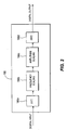
- FIGURE 2 is an exemplary block diagram 200 that is useful for understanding the scaling operation of DSP 186.
- DSP 186 can include a FFT processing element 186a, a frequency scaling element 186b, an amplitude scaling element 186c and an inverse FFT processing element 186d.
- FFT processing element 186a can transform digital audio samples from time domain to their frequency domain equivalents.
- Frequency scaling processing element 186b can be configured to receive the frequency domain audio samples and scale the frequency of the received frequency domain audio samples.
- Amplitude scaling element 186c can be configured to receive the frequency scaled audio samples and scale the amplitude of the received frequency scaled audio samples.
- Inverse FFT processing element 186d can be configured to receive and transform the amplitude scaled audio samples from the frequency domain back to their equivalent time domain audio signals. It should be recognized that although the frequency and amplitude scaling elements are separately shown, the invention is not limited in this regard. For example, a single scaling element can be configured to scale the amplitude and the frequency of audio samples.
- FIGURE 3 is a flowchart that is useful for understanding the inventive arrangements of FIGURE 2 as implemented in an exemplary media player such as device 100.
- the process in FIGURE 3 is described relative to a fast forward playback since audio playback in reverse trick modes is generally not desirable. It should be understood however, that the invention is not limited in this regard.
- the inventive arrangements as described herein could be applied to reverse playback trick modes using similar techniques as described in FIGURE 3 .
- control CPU 122 can monitor user inputs from the advanced features buffer 136.
- control CPU 122 can determine whether the trick mode fast forward playback speed is selected. In a case where it has been determined that the trick mode fast forward playback has been selected, the control CPU 122 can continue to steps 315 through 345 for trick mode playback. Otherwise, control returns to processing step 300.
- packet video decoder 178 can be configured to provide video playback at faster than normal speeds. For example, the simplest approach would be to cause the packet video decoder to simply drop certain decoded pictures. For example, every other picture to be displayed can be dropped in the case of 2X playback. However, it will be appreciated that other approaches can also be used to alter the video playback speed and the invention is not limited to any particular method of implementing a faster than normal video playback.
- step 315 the control CPU 122 can determine n, where n is the video trick mode playback speed relative to the normal playback speed.
- step 320 the audio data for the segment of the video presentation that is being played back in the video trick mode can be read.
- the control CPU 122 can configure the audio decoder 182 or DSP 186 to drop selected audio samples by dropping audio samples at a rate of (n-1) of every n samples. Dropping audio samples in this manner has the advantageous effect of speeding up the audio to substantially match the speed of the video. However, if the remaining audio samples were simply passed to the audio D/A 184 for subsequent conversion to analog format, then the result would be a change in frequency of the audio by a factor of n . This change in frequency can cause voices to be high pitched and difficult to understand. Accordingly, the digital audio output from the audio decoder 182 can be processed by DSP 186.
- the DSP can transform remaining audio samples from time domain to their corresponding frequency domain equivalents.
- Control CPU 122 can advantageously select the DSP 186 as the input for audio D/A 184.
- the DSP 186 can receive digitized audio from the audio decoder 182 and processes such audio to create more natural sounding audio. More particularly, in step 330 the DSP 186 can configure the FFT processing element 186a to transform received audio signals that are in the time domain, to frequency domain audio signals.
- DSP 186 can configure frequency scaling element 186b to scale the frequency of the frequency domain audio signal by a factor 1/ n .
- DSP 186 can also configure amplitude scaling element 186c to scale the amplitude of the frequency domain signals by 1/ n .
- scaling the amplitude of the audio signal can reduce the energy content of the audio signal making the signal more manageable for processing.
- step 340 the scaled audio signals that are in the frequency domain can be transformed back to the time domain using an inverse fast Fourier transform or IFFT processing element 186d.
- the pitch or frequency of the digitized audio can be scaled up or down in order to compensate for the selective elimination of audio samples in step 325 associated with the change in the playback speed.
- step 345 the frequency and amplitude scaled time domain audio signal can be used to generate the playback signal, and the trick mode playback is performed with the player 100 configured as described.
- step 350 a determination is made whether to continue scaling the audio signal.
- Control CPU 122 can periodically check advanced feature processor 136 to determine whether fast forward playback mode has been terminated or is still selected. In the case where the fast forward playback mode has been selected, then the control CPU 122 can return to step 320 and continues trick mode playback. In the case where the current fast forward playback mode has been deselected, that is, the user has commanded that the trick mode playback be discontinued, then control can return to step 310.
- n will be a value less than 1x.
- n 1 ⁇ 2 for 50% slower playback.
- selected time domain audio samples can be repeated at a rate inversely proportional to the slow playback speed n to generate an audio playback signal.
- the audio samples can be repeated at an average rate of about 1/ n .
- the frequency scaling element 186b can be configured to scale the frequency of the audio samples by a factor of 1/ n .
- the amplitude scaling element 186c can be configured to scale the amplitude of the audio samples by a factor n , rather than 1/n factor used for fast playback modes.
- the present invention can be realized in hardware, software, or a combination of hardware and software.
- Machine readable storage according to the present invention can be realized in a centralized fashion in one computer system, for example the control CPU 122, or in a distributed fashion where different elements are spread across several interconnected computer systems. Any kind of computer system or other apparatus adapted for carrying out the methods described herein is acceptable.
- the present invention as described herein contemplates the control CPU 122 of FIGURE 1
- a typical combination of hardware and software could be a general purpose computer system with a computer program that, when being loaded and executed, controls the computer system and a DVD player system similar to that shown in FIGURE 1 such that it carries out the methods described herein.
- the present invention can also be embedded in a computer program product which comprises all the features enabling the implementation of the methods described herein, and which when loaded in a computer system is able to carry out these methods.
- a computer program in the present context can mean any expression, in any language, code or notation, of a set of instructions intended to cause a system having an information processing capability to perform a particular function either directly or after either or both of the following: (a) conversion to another language, code or notation; and (b) reproduction in a different material form.
Description
- The invention concerns improved trick mode playback, and more particularly to improvements in the trick mode playback of audio soundtrack associated with a video segment played back at a faster or slower than normal speed.
- DVD trick modes can include speedup or slowdown of normal playback to either search for a specific location on the disc or to look at picture details that would be missed at normal play speed. By convention, normal playback speed can be denoted as 1X. Both audio and video trick modes are possible and both can be found on commercially available DVD players. However, conventional methods for playback of audio at fast or slow speed have proved to be problematic. The advancement of digital signal processors and especially audio digital signal processors that are used in currently available products have created the possibility for more sophisticated real-time processing for improved audio trick modes.
- One problem with the use of video trick modes concerns the treatment of audio content corresponding to a playback video segment. For example, when a user speeds up or slows down a displayed video segment, the corresponding audio segment that is played back can be distorted. Typically, audio samples in the audio segment can be shifted to higher frequencies during a fast trick mode, and to lower frequencies during a slow trick mode. The fast trick modes that increase the playback speed by a factor of between about 1.5 to 3 times as compared to normal playback will tend to cause human speech to sound higher in pitch. This higher pitched audio playback, the chipmunk effect, can be annoying and in many instances may be unintelligible to a listener. Conversely, slow frequency trick modes can produce a low frequency wobble that may be understandable but not aurally pleasing.
- In order to obtain the most useful audio playback during video trick modes as described herein, it is also necessary to consider the nature of the particular trick mode. For example, while it may be possible to utilize various techniques to provide intelligible audio for 1.5X or 2X trick modes, such techniques may provide unsatisfactory results when the trick mode involves playback at 5X or 10X. At such high playback speeds, any attempt to play back audio programming in synchronism with the video content may result in unintelligible speech due to the very rapid rate at which words would need to be presented.
- To avoid hearing various types of audio artifacts that can result during DVD trick modes, conventional DVD players will often mute the audio during video trick modes. However, this is not an entirely satisfactory solution as the audio may be of interest in such modes. Accordingly, it would be advantageous if a DVD player could playback audio in a manner that overcomes the limitations of the prior art and achieves a desirable and aurally pleasant playback of audio program content during video trick mode operation.
-
US-A-5893062 discloses a variable-rate playback with synchronized audio. The audiovisual data are analyzed, and the audio is modified such that it has little or no distortion. - The invention concerns a method and apparatus for improved playback of audio programming during video trick modes. The trick mode can provide a playback speed that is faster or slower than normal 1X play speed. The coded digital data can comprise video programming with corresponding audio content. A decoder can be configured to decode from a portion of the digital data comprising the audio content, a plurality of digital audio samples corresponding to a selected portion of the video presentation. Subsequently, a digital signal processor (DSP) can translate the audio samples from time domain to frequency domain and scale a playback audio frequency associated with the audio samples to compensate for the changed audio pitch resulting from the trick mode playback speed.
- According to one aspect of the invention, for fast trick modes, the decoder can drop selected ones of the audio samples at a rate approximately corresponding to a selected trick mode video playback speed of the video presentation. A digital-to-analog (D/A) converter can subsequently generate an audio playback signal corresponding only to a remaining set of the audio samples. The audio samples can be dropped at an average rate of approximately (n-1) of every n samples, where n is equal to the selected trick mode playback speed relative to a normal playback speed. In order to compensate for the dropped audio samples, the DSP can transform the audio samples, which are in the time domain, to their frequency domain equivalent and preferably frequency scale the playback audio pitch by a factor of approximately 1/n. Additionally, the amplitude of the audio samples can be scaled by a factor of approximately 1/n. Subsequent to amplitude and frequency scaling the frequency domain audio samples, the DSP can transform the scaled frequency domain audio samples into to their corresponding time domain equivalent for playback.
- According to an alternative aspect, for slow speed trick modes, the decoder can repeat selected ones of the audio samples at a rate that is inversely proportional to a selected trick mode video playback speed of said video presentation. This can produce a trick mode set of audio samples. The trick mode audio samples can subsequently be provided to the digital to analog converter to generate an audio playback signal corresponding to the trick mode set of audio samples. The audio samples can be repeated 1/n times, where n is equal to the selected trick mode playback speed relative to a normal playback speed. In order to compensate for the additional audio samples, the DSP can transform the audio samples from time domain to frequency domain and frequency scale the playback audio frequency by a multiplying factor of approximately 1/n. The amplitude of the frequency domain audio samples can also be scaled by a factor of approximately n. The DSP can subsequently transform the frequency and amplitude scaled frequency domain audio samples into their time domain equivalents for playback.
-
-
FIGURE 1 is a block diagram of a DVD device that can be provided with one or more advanced operating features in accordance with the inventive arrangements. -
FIGURE 2 is a block diagram useful for understanding frequency and amplitude scaling by utilizing a DSP in accordance with the invention. -
FIGURE 3 is a flowchart useful for understanding the inventive arrangements ofFIGURE 2 as implemented in an exemplary unit such asdevice 100 ofFIGURE 1 . - The present invention can provide substantially normal audio playback during video trick modes in any type of digital video recorded on any suitable digital data storage medium. For convenience, the invention shall be described in the context of a DVD medium utilizing conventional MPEG-1 or MPEG-2 format. However, those skilled in the art will appreciate that the invention is not limited in this regard. The digital data storage medium can include any media that is capable of storing substantial amounts of digital data for retrieval and playback at a subsequent time. As used herein, a storage medium can include, but is not limited to, optical, magnetic and electronic means for storing data. Exemplary digital storage media can include an optical digital versatile disk (DVD), magneto-optical disk, a magnetic hard disk, a video CD or regular CD, or solid-state memory such as dynamic random access memory (DRAM) or synchronous DRAM (SDRAM).
- A storage medium reader is provided for reading coded digital data from a digital data storage medium.
FIGURE 1 is a block diagram of an exemplary DVD video player in which the present invention may be implemented. Thedevice 100 can have the capability to read stored data from a digital storage medium. Referring toFIGURE 1 , the storage medium can be a re-writable disk,DVD 102.Device 100 can include amechanical assembly 104, acontrol section 120, and an audio/video (A/V)output processing section 170. The allocation of most of the blocks to different sections is self-evident, whereas the allocation of some of the blocks is made for purposes of convenience and is not critical to understanding the operation of thedevice 100. Importantly, it should be recognized that if the digital data storage medium were a solid-state device, themechanical assembly 104 would not be necessary to practice the invention. In this case, the coded digital data stored in the digital storage medium can be directly accessed bycontrol CPU 122 and buffered intrack buffer 172. - Notwithstanding, the
mechanical assembly 104 can include amotor 106 forspinning disk 102 and apickup assembly 108 adapted to be moved over thespinning DVD 102. A laser mounted on thepickup assembly 108 can illuminate data already stored onto the track for playing back video and/or audio program data. For purposes of understanding the invention, it is irrelevant whether the disc is recordable. The laser mounted on thepickup assembly 108 and themotor 106 can be controlled by aservo 110. Theservo 110 can also be configured to receive an input playback signal representing data read from spiral tracks on theDVD 102. The playback signal can also serve as an input to anerror correction circuit 130, which can be considered part of thecontrol section 120 or part of the A/Voutput processing section 170. - The
control section 120 can include a control central processing unit (CPU) 122. Theservo 110 can also be considered part of thecontrol section 120. Suitable software or firmware can be provided in a memory for the conventional operations performed bycontrol CPU 122. In addition, program routines for the advanced features as described herein can be provided for controllingCPU 122. The program routines can include application code and/or firmware code. - A control buffer 132 for viewer activatable functions can be configured to indicate those functions presently available, namely play, reverse, fast forward, slow play, pause/play and stop. The pause function is analogous to a pause operation typically found on most videocassette recorders (VCRs). The pause function can have the capability to manual interrupt the playback of a prerecorded presentation in order to halt or eliminate undesired segments such as commercials, from a playback. Advanced features
buffer 136 can be provided for implementing other advanced playback functions, including control of trick modes as described herein. Playback trick modes can include forward and reverse playback at speeds other than standard 1X playback speed. - The
output processing section 170 can include anerror correction block 130 and a track buffer oroutput buffer 172, in which data read from the disc can be buffered and assembled into packets for further processing. The packets can be processed byconditional access circuit 174 that controls propagation of the packets throughdemultiplexer 176 and into respective paths for video and audio processing. The video can be decoded bydecoder 178, for example from MPEG-1 or MPEG-2 formats, and encoded to form a conventional television signal format such as ATSC, NTSC, SECAM or PAL. The audio can be decoded bydecoder 182, for example from MPEG-1 or MPEG-2 formats, and converted to analog form by audio digital-to-analog (D/A)converter 184. The audio D/A 184 can process digital audio received from theaudio decoder 182 and produce an analog output signal. - The
player 100 can preferably include a digital signal processor (DSP) 186, which can be controlled by thecontrol CPU 122.Digital signal processor 186 can perform audio frequency scaling during video trick modes.Digital signal processor 186 can receive fromaudio decoder 184, digital audio samples corresponding to a selected video presentation being played. In standard, non-trick modes,DSP 186 can remain inactive and the audio D/A 184 can process digital audio received from theaudio decoder 182. However, when a trick mode playback has been selected, the audio D/A 184 can be configured to receive specially processed digital audio from theDSP 186. -
Digital signal processor 186 can be any commercially available processor that is designed to perform conventional audio processing functions, provided however that theDSP 186 can be configured to perform frequency and amplitude scaling. To facilitate scaling of the frequency and amplitude of an input audio signal, the DSP can convert the input audio signal that is in the time domain to a frequency domain audio signal. The frequency domain audio signal can be scaled and subsequently transformed back to a time domain audio signal. Digital signal processors commonly make use of various audio processing algorithms and techniques for accomplishing frequency and amplitude scaling. Notwithstanding, the invention is not limited in this regard. -
Digital signal processor 186 can be a customized processor that can be used for frequency scaling. A field programmable gate array (FPGA) can be customized to include all the audio processing circuitry that is necessary for receiving a time domain audio signal, converting the received signal to a frequency domain signal, scaling the converted signal and converting the scaled signal to a scaled time-domain audio signal. Other customized processors can include, but are not limited to, application specific integrated circuits (ASICs) and system-on-chip (SoC) applications. A FPGA can be designed with the appropriate cores to include a DSP engine, a decoder, a fast Fourier transform or FFT processing element, an inverse FFT processing element, and a scaling element that can scale frequency and amplitude. -
FIGURE 2 is an exemplary block diagram 200 that is useful for understanding the scaling operation ofDSP 186. As shown inFIGURE 2 ,DSP 186 can include aFFT processing element 186a, afrequency scaling element 186b, anamplitude scaling element 186c and an inverseFFT processing element 186d.FFT processing element 186a can transform digital audio samples from time domain to their frequency domain equivalents. Frequencyscaling processing element 186b can be configured to receive the frequency domain audio samples and scale the frequency of the received frequency domain audio samples.Amplitude scaling element 186c can be configured to receive the frequency scaled audio samples and scale the amplitude of the received frequency scaled audio samples. InverseFFT processing element 186d can be configured to receive and transform the amplitude scaled audio samples from the frequency domain back to their equivalent time domain audio signals. It should be recognized that although the frequency and amplitude scaling elements are separately shown, the invention is not limited in this regard. For example, a single scaling element can be configured to scale the amplitude and the frequency of audio samples. -
FIGURE 3 is a flowchart that is useful for understanding the inventive arrangements ofFIGURE 2 as implemented in an exemplary media player such asdevice 100. The process inFIGURE 3 is described relative to a fast forward playback since audio playback in reverse trick modes is generally not desirable. It should be understood however, that the invention is not limited in this regard. The inventive arrangements as described herein could be applied to reverse playback trick modes using similar techniques as described inFIGURE 3 . - The process can begin at
step 300 when the unit is operated in a playback mode. Instep 305,control CPU 122 can monitor user inputs from theadvanced features buffer 136. Instep 310, thecontrol CPU 122 can determine whether the trick mode fast forward playback speed is selected. In a case where it has been determined that the trick mode fast forward playback has been selected, thecontrol CPU 122 can continue tosteps 315 through 345 for trick mode playback. Otherwise, control returns to processingstep 300. - If a fast playback trick mode has been selected in
step 310, thecontrol CPU 122 can reconfigurepacket video decoder 178 to perform trick mode video playback at speed nX where n is equal to the selected trick mode playback speed relative to a normal playback speed 1 X. If the playback speed is two times faster than normal playback speed, then n = 2. There are a variety of ways in whichpacket video decoder 178 can be configured to provide video playback at faster than normal speeds. For example, the simplest approach would be to cause the packet video decoder to simply drop certain decoded pictures. For example, every other picture to be displayed can be dropped in the case of 2X playback. However, it will be appreciated that other approaches can also be used to alter the video playback speed and the invention is not limited to any particular method of implementing a faster than normal video playback. - In
step 315, thecontrol CPU 122 can determine n, where n is the video trick mode playback speed relative to the normal playback speed. Instep 320, the audio data for the segment of the video presentation that is being played back in the video trick mode can be read. - In
step 325, thecontrol CPU 122 can configure theaudio decoder 182 orDSP 186 to drop selected audio samples by dropping audio samples at a rate of (n-1) of every n samples. Dropping audio samples in this manner has the advantageous effect of speeding up the audio to substantially match the speed of the video. However, if the remaining audio samples were simply passed to the audio D/A 184 for subsequent conversion to analog format, then the result would be a change in frequency of the audio by a factor of n. This change in frequency can cause voices to be high pitched and difficult to understand. Accordingly, the digital audio output from theaudio decoder 182 can be processed byDSP 186. - In
step 330, the DSP can transform remaining audio samples from time domain to their corresponding frequency domain equivalents.Control CPU 122 can advantageously select theDSP 186 as the input for audio D/A 184. TheDSP 186 can receive digitized audio from theaudio decoder 182 and processes such audio to create more natural sounding audio. More particularly, instep 330 theDSP 186 can configure theFFT processing element 186a to transform received audio signals that are in the time domain, to frequency domain audio signals. - In
step 335,DSP 186 can configurefrequency scaling element 186b to scale the frequency of the frequency domain audio signal by afactor 1/n.DSP 186 can also configureamplitude scaling element 186c to scale the amplitude of the frequency domain signals by 1/n. Advantageously, scaling the amplitude of the audio signal can reduce the energy content of the audio signal making the signal more manageable for processing. - In
step 340, the scaled audio signals that are in the frequency domain can be transformed back to the time domain using an inverse fast Fourier transform orIFFT processing element 186d. Notably, by utilizing the frequency and amplitude scaling function of theDSP 186, the pitch or frequency of the digitized audio can be scaled up or down in order to compensate for the selective elimination of audio samples instep 325 associated with the change in the playback speed. - In
step 345, the frequency and amplitude scaled time domain audio signal can be used to generate the playback signal, and the trick mode playback is performed with theplayer 100 configured as described. Instep 350, a determination is made whether to continue scaling the audio signal.Control CPU 122 can periodically checkadvanced feature processor 136 to determine whether fast forward playback mode has been terminated or is still selected. In the case where the fast forward playback mode has been selected, then thecontrol CPU 122 can return to step 320 and continues trick mode playback. In the case where the current fast forward playback mode has been deselected, that is, the user has commanded that the trick mode playback be discontinued, then control can return to step 310. - The inventive arrangements as described herein can be applied to slow playback trick modes using the same techniques as described in
FIGURE 3 . In this case n will be a value less than 1x. For example, n= ½ for 50% slower playback. Further, instep 325, rather than dropping samples, selected time domain audio samples can be repeated at a rate inversely proportional to the slow playback speed n to generate an audio playback signal. The audio samples can be repeated at an average rate of about 1/n. Instep 335, thefrequency scaling element 186b can be configured to scale the frequency of the audio samples by a factor of 1/n. However, for the slow speed playback case, theamplitude scaling element 186c can be configured to scale the amplitude of the audio samples by a factor n, rather than 1/n factor used for fast playback modes. - Notably, the present invention can be realized in hardware, software, or a combination of hardware and software. Machine readable storage according to the present invention can be realized in a centralized fashion in one computer system, for example the
control CPU 122, or in a distributed fashion where different elements are spread across several interconnected computer systems. Any kind of computer system or other apparatus adapted for carrying out the methods described herein is acceptable. - Specifically, although the present invention as described herein contemplates the
control CPU 122 ofFIGURE 1 , a typical combination of hardware and software could be a general purpose computer system with a computer program that, when being loaded and executed, controls the computer system and a DVD player system similar to that shown inFIGURE 1 such that it carries out the methods described herein. The present invention can also be embedded in a computer program product which comprises all the features enabling the implementation of the methods described herein, and which when loaded in a computer system is able to carry out these methods. - A computer program in the present context can mean any expression, in any language, code or notation, of a set of instructions intended to cause a system having an information processing capability to perform a particular function either directly or after either or both of the following: (a) conversion to another language, code or notation; and (b) reproduction in a different material form.
Claims (11)
- A method for playing an audio track during video trick mode playback of a video presentation, including the steps:- reading digital data (320) from a storage medium (102), said digital data representing audio program corresponding to the video presentation;- decoding a plurality of digital audio samples (325) corresponding to a selected portion of the video presentation from a portion of said read digital data, and wherein n is equal to the selected trick mode playback speed relative to a normal playback speed, characterized by:- when the playback speed is faster than the normal playback speed, dropping digital audio samples at an average rate of n-1 every n samples, and when the playback speed is slower than the normal playback speed, repeating the digital audio samples 1/n times;- transforming said digital audio samples (330) from their time domain to the corresponding frequency domain, thereby obtaining frequency domain audio samples;- scaling a playback audio frequency (335) by a multiplying factor of 1/n of said frequency domain audio samples with said trick mode playback.
- Method according to claim 1, further including the step of generating an audio playback signal (345) corresponding only to a remaining set of said audio samples.
- Method according to claim 1 or 2, wherein said scaling step (335) further comprises scaling an amplitude of said frequency domain audio samples by factor of approximately 1/n.
- Method according to one of claims 1 to 3, wherein said scaling step (335) further comprises transforming said scaled frequency domain audio samples to corresponding time domain digital audio samples.
- Method according to one of claims 1 to 4, wherein said storage medium (102) is selected from the group consisting of a DVD, a magneto-optical disk, a magnetic hard disk, a video CD, and a solid state memory device.
- Method according to one of claims 1 to 5, wherein said coded digital data has an MPEG format and said reading step (300) further comprises decoding an MPEG bit stream to obtain said audio samples.
- An apparatus (100) for playing an audio track during video trick mode playback of a video presentation, said apparatus including:- a storage medium reader for reading digital data from a storage medium (102), said digital data comprising audio program corresponding to the video presentation;- a decoder (182) for decoding from a portion of said read digital data representative of said audio program, a plurality of digital audio samples corresponding to a selected portion of the video presentation, and wherein n is equal to the selected trick mode playback speed relative to a normal playback speed,
characterized by:when the playback speed is faster than the normal playback speed, at least one of the decoder and a digital signal processor drops digital audio samples at an average rate of n-1 every n samples, and when the playback speed is slower than the normal playback speed, at least one of the decoder and a digital signal processor repeats the digital audio samples 1/n times;- a digital signal processor DSP (186) comprising a fast Fourier transform (FFT) processing element for transforming said digital audio samples from their time domain to the corresponding frequency domain audio samples,said digital signal processor comprising a scaling element for scaling a playback audio frequency of said frequency domain audio samples by a multiplying factor of 1/n with said trick mode playback. - Apparatus according to claim 7, wherein said scaling element further comprises an amplitude adjusting element (186c) for scaling an amplitude of said frequency domain audio samples by a factor of approximately 1/n.
- Apparatus according to claim 7 or 8, wherein said DSP (186) further comprises an inverse FFT processing element (IFFT, 186d) for transforming said scaled frequency domain audio samples to corresponding time domain digital audio samples for said audio playback signal.
- Apparatus according to one of claims 7 to 9, wherein said storage medium (102) is selected from the group consisting of a DVD, a magneto-optical disk, a magnetic hard disk, a video CD, and a solid state memory device.
- Apparatus according to one of claims 7 to 10, wherein said coded digital data has an MPEG format and said reader further is being adapted for decoding an MPEG bit stream to obtain said audio samples.
Applications Claiming Priority (3)
| Application Number | Priority Date | Filing Date | Title |
|---|---|---|---|
| US86649 | 2002-03-01 | ||
| US10/086,649 US7809241B2 (en) | 2002-03-01 | 2002-03-01 | Audio frequency scaling during video trick modes utilizing digital signal processing |
| PCT/US2003/004917 WO2003075565A1 (en) | 2002-03-01 | 2003-02-19 | Audio frequency scaling during video trick modes utilizing digital signal processing |
Publications (3)
| Publication Number | Publication Date |
|---|---|
| EP1483908A1 EP1483908A1 (en) | 2004-12-08 |
| EP1483908A4 EP1483908A4 (en) | 2009-02-25 |
| EP1483908B1 true EP1483908B1 (en) | 2012-10-10 |
Family
ID=27787506
Family Applications (1)
| Application Number | Title | Priority Date | Filing Date |
|---|---|---|---|
| EP03743682A Expired - Fee Related EP1483908B1 (en) | 2002-03-01 | 2003-02-19 | Audio frequency scaling during video trick modes utilizing digital signal processing |
Country Status (11)
| Country | Link |
|---|---|
| US (1) | US7809241B2 (en) |
| EP (1) | EP1483908B1 (en) |
| JP (1) | JP4236589B2 (en) |
| KR (1) | KR100943596B1 (en) |
| CN (1) | CN100380950C (en) |
| AU (1) | AU2003211150A1 (en) |
| MX (1) | MXPA04008427A (en) |
| MY (1) | MY135304A (en) |
| PL (1) | PL372229A1 (en) |
| TW (1) | TWI237240B (en) |
| WO (1) | WO2003075565A1 (en) |
Families Citing this family (14)
| Publication number | Priority date | Publication date | Assignee | Title |
|---|---|---|---|---|
| US7489362B2 (en) | 2003-03-04 | 2009-02-10 | Broadcom Corporation | Television functionality on a chip |
| US20050036074A1 (en) * | 2003-08-15 | 2005-02-17 | Broadcom Corporation | Method and system for a digital interface for TV stereo audio decoding |
| WO2008124548A1 (en) * | 2007-04-04 | 2008-10-16 | Visible World Inc. | Systems and methods for modifying commercials |
| JP2010283605A (en) * | 2009-06-04 | 2010-12-16 | Canon Inc | Video processing device and method |
| CN101635160B (en) * | 2009-06-17 | 2012-03-21 | 深圳市美赛达科技有限公司 | Music frequency spectrum analyzing method, music frequency spectrum display device and music playing device |
| US20100329638A1 (en) * | 2009-06-29 | 2010-12-30 | Nortel Networks Limited | Method and apparatus for independent licensing of audio in distribution of audiovisual assets |
| EP2680616A1 (en) * | 2012-06-25 | 2014-01-01 | LG Electronics Inc. | Mobile terminal and audio zooming method thereof |
| US9513688B2 (en) | 2013-03-16 | 2016-12-06 | Intel Corporation | Measurement of performance scalability in a microprocessor |
| CN105513598B (en) * | 2016-01-14 | 2019-04-23 | 宁波大学 | A kind of voice playback detection method based on the distribution of frequency domain information amount |
| CN108810575B (en) * | 2017-05-04 | 2021-10-29 | 杭州海康威视数字技术股份有限公司 | Method and device for sending target video |
| CN110661760A (en) * | 2018-06-29 | 2020-01-07 | 视联动力信息技术股份有限公司 | Data processing method and device |
| US11102523B2 (en) | 2019-03-19 | 2021-08-24 | Rovi Guides, Inc. | Systems and methods for selective audio segment compression for accelerated playback of media assets by service providers |
| US10708633B1 (en) | 2019-03-19 | 2020-07-07 | Rovi Guides, Inc. | Systems and methods for selective audio segment compression for accelerated playback of media assets |
| US11039177B2 (en) * | 2019-03-19 | 2021-06-15 | Rovi Guides, Inc. | Systems and methods for varied audio segment compression for accelerated playback of media assets |
Family Cites Families (17)
| Publication number | Priority date | Publication date | Assignee | Title |
|---|---|---|---|---|
| JPS5630376A (en) * | 1979-08-15 | 1981-03-26 | Discovision Ass | Method of determining signal form |
| US4727433A (en) * | 1982-01-25 | 1988-02-23 | Discovision Associates | Video/audio coded data recovery from a record medium |
| US5623344A (en) * | 1992-09-01 | 1997-04-22 | Hitachi America, Ltd. | Digital video recording device with trick play capability |
| JPH06139289A (en) | 1992-10-26 | 1994-05-20 | Olympus Optical Co Ltd | Information reproducing device |
| JPH08287612A (en) | 1995-04-14 | 1996-11-01 | Sony Corp | Variable speed reproducing method for audio data |
| DE69734961T2 (en) * | 1996-10-15 | 2006-08-24 | Matsushita Electric Industrial Co., Ltd., Kadoma | Method for video and audio coding and device for coding |
| US5893062A (en) | 1996-12-05 | 1999-04-06 | Interval Research Corporation | Variable rate video playback with synchronized audio |
| US6154603A (en) | 1997-02-18 | 2000-11-28 | Thomson Licensing S.A. | Picture decoding for trick mode operation |
| US6356211B1 (en) * | 1997-05-13 | 2002-03-12 | Sony Corporation | Encoding method and apparatus and recording medium |
| JP3073942B2 (en) | 1997-09-12 | 2000-08-07 | 日本放送協会 | Audio processing method, audio processing device, and recording / reproducing device |
| JP3017715B2 (en) | 1997-10-31 | 2000-03-13 | 松下電器産業株式会社 | Audio playback device |
| US6385704B1 (en) * | 1997-11-14 | 2002-05-07 | Cirrus Logic, Inc. | Accessing shared memory using token bit held by default by a single processor |
| JPH11213557A (en) | 1998-01-26 | 1999-08-06 | Sony Corp | Reproducing device |
| JP2000082260A (en) * | 1998-09-04 | 2000-03-21 | Sony Corp | Device and method for reproducing audio signal |
| JP3721009B2 (en) | 1999-05-31 | 2005-11-30 | 株式会社リコー | Recording viewing system |
| JP3557371B2 (en) * | 1999-07-15 | 2004-08-25 | 松下電器産業株式会社 | AV decoder control method and AV decoder control device |
| JP4895418B2 (en) * | 1999-08-24 | 2012-03-14 | ソニー株式会社 | Audio reproduction method and audio reproduction apparatus |
-
2002
- 2002-03-01 US US10/086,649 patent/US7809241B2/en not_active Expired - Fee Related
-
2003
- 2003-02-19 JP JP2003573869A patent/JP4236589B2/en not_active Expired - Fee Related
- 2003-02-19 PL PL03372229A patent/PL372229A1/en not_active Application Discontinuation
- 2003-02-19 AU AU2003211150A patent/AU2003211150A1/en not_active Abandoned
- 2003-02-19 EP EP03743682A patent/EP1483908B1/en not_active Expired - Fee Related
- 2003-02-19 KR KR1020047013583A patent/KR100943596B1/en not_active IP Right Cessation
- 2003-02-19 WO PCT/US2003/004917 patent/WO2003075565A1/en active Application Filing
- 2003-02-19 MX MXPA04008427A patent/MXPA04008427A/en not_active Application Discontinuation
- 2003-02-19 CN CNB038093170A patent/CN100380950C/en not_active Expired - Fee Related
- 2003-02-26 TW TW092104043A patent/TWI237240B/en not_active IP Right Cessation
- 2003-02-27 MY MYPI20030702A patent/MY135304A/en unknown
Also Published As
| Publication number | Publication date |
|---|---|
| US20030165084A1 (en) | 2003-09-04 |
| MXPA04008427A (en) | 2004-11-26 |
| PL372229A1 (en) | 2005-07-11 |
| KR20040093084A (en) | 2004-11-04 |
| WO2003075565A1 (en) | 2003-09-12 |
| AU2003211150A1 (en) | 2003-09-16 |
| TWI237240B (en) | 2005-08-01 |
| CN1650618A (en) | 2005-08-03 |
| EP1483908A4 (en) | 2009-02-25 |
| JP2005519420A (en) | 2005-06-30 |
| TW200304123A (en) | 2003-09-16 |
| CN100380950C (en) | 2008-04-09 |
| JP4236589B2 (en) | 2009-03-11 |
| EP1483908A1 (en) | 2004-12-08 |
| MY135304A (en) | 2008-03-31 |
| KR100943596B1 (en) | 2010-02-24 |
| US7809241B2 (en) | 2010-10-05 |
Similar Documents
| Publication | Publication Date | Title |
|---|---|---|
| US7130528B2 (en) | Audio data deletion and silencing during trick mode replay | |
| EP1483908B1 (en) | Audio frequency scaling during video trick modes utilizing digital signal processing | |
| EP1596389A2 (en) | System and method for high-quality variable speed playback | |
| US7149412B2 (en) | Trick mode audio playback | |
| EP1481544B1 (en) | Gated silence removal during video trick modes | |
| US7889969B2 (en) | Audio frequency shifting during video trick modes | |
| JP4542805B2 (en) | Variable speed reproduction method and apparatus, and program | |
| JP2006317768A (en) | Speaking speed conversion apparatus and speaking speed conversion program for controlling the speaking speed conversion apparatus | |
| JPH0854895A (en) | Reproducing device | |
| JP2004303409A (en) | Digital voice signal reproduction system | |
| JP2007101644A (en) | Voice reproducing apparatus | |
| JP2003339022A (en) | Disk reproducing apparatus and recording medium reproducing apparatus |
Legal Events
| Date | Code | Title | Description |
|---|---|---|---|
| PUAI | Public reference made under article 153(3) epc to a published international application that has entered the european phase |
Free format text: ORIGINAL CODE: 0009012 |
|
| 17P | Request for examination filed |
Effective date: 20040827 |
|
| AK | Designated contracting states |
Kind code of ref document: A1 Designated state(s): AT BE BG CH CY CZ DE DK EE ES FI FR GB GR HU IE IT LI LU MC NL PT SE SI SK TR |
|
| AX | Request for extension of the european patent |
Extension state: AL LT LV MK RO |
|
| RAP1 | Party data changed (applicant data changed or rights of an application transferred) |
Owner name: THOMSON LICENSING |
|
| A4 | Supplementary search report drawn up and despatched |
Effective date: 20090127 |
|
| RIC1 | Information provided on ipc code assigned before grant |
Ipc: H04N 5/783 20060101AFI20090121BHEP |
|
| 17Q | First examination report despatched |
Effective date: 20090804 |
|
| RAP1 | Party data changed (applicant data changed or rights of an application transferred) |
Owner name: THOMSON LICENSING |
|
| GRAP | Despatch of communication of intention to grant a patent |
Free format text: ORIGINAL CODE: EPIDOSNIGR1 |
|
| GRAS | Grant fee paid |
Free format text: ORIGINAL CODE: EPIDOSNIGR3 |
|
| GRAA | (expected) grant |
Free format text: ORIGINAL CODE: 0009210 |
|
| AK | Designated contracting states |
Kind code of ref document: B1 Designated state(s): DE FR GB IT |
|
| REG | Reference to a national code |
Ref country code: GB Ref legal event code: FG4D |
|
| REG | Reference to a national code |
Ref country code: GB Ref legal event code: 746 Effective date: 20121016 |
|
| REG | Reference to a national code |
Ref country code: DE Ref legal event code: R096 Ref document number: 60342313 Country of ref document: DE Effective date: 20121206 |
|
| PLBE | No opposition filed within time limit |
Free format text: ORIGINAL CODE: 0009261 |
|
| STAA | Information on the status of an ep patent application or granted ep patent |
Free format text: STATUS: NO OPPOSITION FILED WITHIN TIME LIMIT |
|
| PG25 | Lapsed in a contracting state [announced via postgrant information from national office to epo] |
Ref country code: IT Free format text: LAPSE BECAUSE OF FAILURE TO SUBMIT A TRANSLATION OF THE DESCRIPTION OR TO PAY THE FEE WITHIN THE PRESCRIBED TIME-LIMIT Effective date: 20121010 |
|
| 26N | No opposition filed |
Effective date: 20130711 |
|
| REG | Reference to a national code |
Ref country code: DE Ref legal event code: R097 Ref document number: 60342313 Country of ref document: DE Effective date: 20130711 |
|
| REG | Reference to a national code |
Ref country code: FR Ref legal event code: PLFP Year of fee payment: 14 |
|
| REG | Reference to a national code |
Representative=s name: HOFSTETTER, SCHURACK & PARTNER PATENT- UND REC, DE Ref country code: DE Ref legal event code: R082 Ref document number: 60342313 Country of ref document: DE Ref country code: DE Ref legal event code: R082 Ref document number: 60342313 Country of ref document: DE Representative=s name: KASTEL PATENTANWAELTE, DE Ref country code: DE Ref legal event code: R082 Ref document number: 60342313 Country of ref document: DE Representative=s name: HOFSTETTER, SCHURACK & PARTNER - PATENT- UND R, DE |
|
| REG | Reference to a national code |
Representative=s name: HOFSTETTER, SCHURACK & PARTNER - PATENT- UND R, DE Ref country code: DE Ref legal event code: R082 Ref document number: 60342313 Country of ref document: DE Representative=s name: HOFSTETTER, SCHURACK & PARTNER PATENT- UND REC, DE Ref country code: DE Ref legal event code: R082 Ref document number: 60342313 Country of ref document: DE |
|
| REG | Reference to a national code |
Ref country code: FR Ref legal event code: PLFP Year of fee payment: 15 |
|
| REG | Reference to a national code |
Ref country code: DE Ref legal event code: R082 Ref document number: 60342313 Country of ref document: DE Representative=s name: HOFSTETTER, SCHURACK & PARTNER - PATENT- UND R, DE |
|
| REG | Reference to a national code |
Ref country code: FR Ref legal event code: PLFP Year of fee payment: 16 |
|
| PGFP | Annual fee paid to national office [announced via postgrant information from national office to epo] |
Ref country code: GB Payment date: 20200219 Year of fee payment: 18 Ref country code: DE Payment date: 20200211 Year of fee payment: 18 |
|
| PGFP | Annual fee paid to national office [announced via postgrant information from national office to epo] |
Ref country code: FR Payment date: 20200228 Year of fee payment: 18 |
|
| REG | Reference to a national code |
Ref country code: DE Ref legal event code: R119 Ref document number: 60342313 Country of ref document: DE |
|
| GBPC | Gb: european patent ceased through non-payment of renewal fee |
Effective date: 20210219 |
|
| PG25 | Lapsed in a contracting state [announced via postgrant information from national office to epo] |
Ref country code: DE Free format text: LAPSE BECAUSE OF NON-PAYMENT OF DUE FEES Effective date: 20210901 Ref country code: FR Free format text: LAPSE BECAUSE OF NON-PAYMENT OF DUE FEES Effective date: 20210228 Ref country code: GB Free format text: LAPSE BECAUSE OF NON-PAYMENT OF DUE FEES Effective date: 20210219 |