EP1482646B1 - Portable terminal having tuner for changing radiation pattern - Google Patents
Portable terminal having tuner for changing radiation pattern Download PDFInfo
- Publication number
- EP1482646B1 EP1482646B1 EP04012115A EP04012115A EP1482646B1 EP 1482646 B1 EP1482646 B1 EP 1482646B1 EP 04012115 A EP04012115 A EP 04012115A EP 04012115 A EP04012115 A EP 04012115A EP 1482646 B1 EP1482646 B1 EP 1482646B1
- Authority
- EP
- European Patent Office
- Prior art keywords
- main body
- folder
- portable terminal
- current distribution
- distribution element
- Prior art date
- Legal status (The legal status is an assumption and is not a legal conclusion. Google has not performed a legal analysis and makes no representation as to the accuracy of the status listed.)
- Expired - Lifetime
Links
Images






Classifications
-
- H—ELECTRICITY
- H01—ELECTRIC ELEMENTS
- H01Q—ANTENNAS, i.e. RADIO AERIALS
- H01Q1/00—Details of, or arrangements associated with, antennas
- H01Q1/12—Supports; Mounting means
- H01Q1/22—Supports; Mounting means by structural association with other equipment or articles
- H01Q1/24—Supports; Mounting means by structural association with other equipment or articles with receiving set
- H01Q1/241—Supports; Mounting means by structural association with other equipment or articles with receiving set used in mobile communications, e.g. GSM
-
- H—ELECTRICITY
- H01—ELECTRIC ELEMENTS
- H01Q—ANTENNAS, i.e. RADIO AERIALS
- H01Q19/00—Combinations of primary active antenna elements and units with secondary devices, e.g. with quasi-optical devices, for giving the antenna a desired directional characteristic
- H01Q19/005—Patch antenna using one or more coplanar parasitic elements
-
- H—ELECTRICITY
- H04—ELECTRIC COMMUNICATION TECHNIQUE
- H04B—TRANSMISSION
- H04B1/00—Details of transmission systems, not covered by a single one of groups H04B3/00 - H04B13/00; Details of transmission systems not characterised by the medium used for transmission
- H04B1/38—Transceivers, i.e. devices in which transmitter and receiver form a structural unit and in which at least one part is used for functions of transmitting and receiving
- H04B1/3827—Portable transceivers
- H04B1/3833—Hand-held transceivers
- H04B1/3838—Arrangements for reducing RF exposure to the user, e.g. by changing the shape of the transceiver while in use
-
- H—ELECTRICITY
- H04—ELECTRIC COMMUNICATION TECHNIQUE
- H04M—TELEPHONIC COMMUNICATION
- H04M1/00—Substation equipment, e.g. for use by subscribers
- H04M1/02—Constructional features of telephone sets
- H04M1/0202—Portable telephone sets, e.g. cordless phones, mobile phones or bar type handsets
- H04M1/0206—Portable telephones comprising a plurality of mechanically joined movable body parts, e.g. hinged housings
- H04M1/0208—Portable telephones comprising a plurality of mechanically joined movable body parts, e.g. hinged housings characterized by the relative motions of the body parts
- H04M1/0214—Foldable telephones, i.e. with body parts pivoting to an open position around an axis parallel to the plane they define in closed position
- H04M1/0216—Foldable in one direction, i.e. using a one degree of freedom hinge
Definitions
- a tuner i.e. a current distribution element
- portable terminals are equipped with a variety of functions owing to the development of information communication technology, the trend for providing terminals of smaller-size, lighterweight and improved portability.
- the portable terminals were confined to voice call, short message transmission, and the like, whereas they are becoming capable of transmitting/receiving multimedia data such as moving pictures provided by service providers, video conferencing via a wireless Internet, and moving picture mail.
- a portable terminal is a unit that allows a user to wirelessly communicate with another party.
- Portable terminals include HHP (Hand Held Products), CT-2 (Cordless Telephone-2) cellular phones, smart phones, digital phones, PCS (Personal Communication Service) phones, PDAs (Personal Digital Assistants), and laptop computers, typically categorized according to their appearance.
- the portable terminals usually use an LCD (Liquid Crystal Display) as a data output device.
- LCD Liquid Crystal Display
- a keypad a basic data input device, is provided via an arrangement of keys.
- An antenna device is positioned appropriately for receiving a signal. Providing increased efficiency and, as more recently has become an issue, reduced SAR (Specific Absorption Rate) are challenging issues in designing the antenna device.
- whip antenna For applications to conventional portable terminals, whip antenna, helical antenna, sleeve antenna, N-type antenna, chip antenna, and FS-PIFA antenna are provided at the outside of the portable terminal. Thus, these antennas are called external antennas.
- inverted F antenna planar inverted F antenna (PIFA), diversity antenna, microstrip antenna, twisted loop antenna, and EID (Electronic Identification) antenna are internal antennas that can be installed within the portable terminals.
- PIFA planar inverted F antenna
- EID Electronic Identification
- Antennas utilized in portable terminals can also be divided into monopole or planar types according to how they excite radiated electromagnetic waves.
- Monopole type antennas include whip antenna, helical antenna, sleeve antenna, chip antenna, and N-type antenna
- planar type antennas include inverted F antenna, PIFA, diversity antenna, microstrip antenna, EID antenna, FS (FireStick)-PIFA, and RCDLA (Radiation Coupled Dual L-Antenna).
- the monopole antennas can create strong electromagnetic waves that have been alleged to adversely affect the human body. While it is easy to suppress the effects of electromagnetic waves from the planar antennas, these antennas do not have wide bands.
- monopole antennas are external ones
- recently developed antennas include a half-exposed, fixed monopole antenna, an internal monopole antenna with an electromagnetic wave absorber, as well as a SAR-reducing monopole antenna for a folder-type terminal, which have internal structures, operate in wide bands, and provides a low SAR.
- the half-exposed, fixed monopole antenna provide excellent antenna efficiency, but is not as effective in reducing SAR as the wave absorbing internal monopole antenna. To the contrary, although the wave absorbing internal monopole antenna reduces SAR more effectively than the half-exposed, fixed monopole antenna, it has lower antenna efficiency.
- the monopole antenna designed for SAR reduction in a folder-type terminal which was proposed to overcome the above problems, is excellent in both antenna efficiency and SAR reduction.
- an electromagnetic wave absorber is positioned in the vicinity of a hinge device that connects two terminal bodies, electromagnetic wave leakage in the hinge device may lead to a SAR increase.
- a folder-type portable terminal comprises a main body 10 having a plurality of keys 11 which are pressed to enter intended data and a microphone 12, a folder 20 having a main LCD 21, a sub LCD 24 for displaying input data, a speaker 22, a PCB 23 in the folder 20 and a hinge device 30 which connects the body 10 and the folder 20 along a hinge axis A1 and is rotatable so that the folder 20 advances toward or recedes away from the body 10.
- the width of the folder 20 is relatively made wide as compared to its length, or the hinge axis A1 is defined near an antenna device 40 on the main body 10, for sake of fabrication convenience.
- electromagnetic waves from a power supply for the antenna can leak in the hinge device 30, which is positioned between the main body 10 and the folder 20, thereby increasing SAR.
- the antenna is a monopole antenna
- a ground surface perpendicular to an antenna element is needed within an upper portion of the main body 10.
- a sufficient antenna ground area is difficult to ensure and reduction of the thickness of the portable terminal is limited.
- a SAR-reducing folder-type terminal has been developed. It has the same configuration as the conventional folder-type portable terminal, except that an electromagnetic wave reflecting plate is attached on the inner or outer surface of the folder 20 such that it faces the antenna device when the folder 20 is opened.
- the antenna can be a helical antenna, a whip antenna, or a half-exposed, fixed monopole antenna.
- Use the half-exposed, fixed monopole antenna allows the antenna ground surface to be easily obtained by the reflecting plate. If the antenna ground surface must be secured on the upper surface of the main body by using the whip or helical antenna, the ground surface itself will be narrow.
- Folder-type portable terminals typically have a ground larger than 1/4 ⁇ of its operating frequency, e.g. 1800MHz.
- the ground refers to a part of the main body or folder where electrical current flows.
- a radiation pattern can greatly vary. Because there is no specific solutions for SAR reduction, SAR, reduction, attempts have been made to reduce SAR by lowering antenna output, thereby deteriorating the operation characteristics of the antenna device.
- WO 02/071534 refers to a radio communications device comprising an SAR value reducing correction element.
- the radio communications device has at least one additional SAR value reducing correction element provided in and/or on a housing in such a manner that the distribution of any electric current which might be flowing on a printed circuit board is effected form one or more local maxima thereof up to the correction element. It has been found, that in principle, there are two options for reducing specific SAR value. A first option is to move the respective current maximum away from an absorption point. A second option is to reduce the current maximum by a distribution by means of equalizing currents.
- An electrically conductive element used is a single or multilayer, electrically conductive film, coating or another electrically conductive surface element.
- the correction element is in contact with the earth of the printed circuit board only at a single, electrical and mechanical contact point. This contact allows some of the electric current to be diverted from the printed circuit board to the correction element. It can also be adequate for homogenization of the current field taken over the overall cross section (printed circuit board plus correction element) of the mobile radio device for just two separate stripes to be attached as an additional correction element.
- another possibility is to use a wire that is housed between the upper casing and the printed circuit board as and additional, SAR value reducing correction element. This wire is expediently configured so that the one or more maxima of the local current field on the printed circuit board can largely be equalized, so that, taken over the cross section, homogenization of the current amplitude results.
- a conductor can be provided as a SAR value reducing correction element and this is, for example, curved into an L-shape. This has contact with a to the earth of the printed circuit board.
- An aspect of the present invention is to substantially solve at least the above problems and/or disadvantages and to provide at least the advantages below.
- a main body of the terminal has a main body PCB and a main body ground defined in the main body PCB.
- a folder is rotatably connected to the main body by a hinge device.
- An antenna device is provided at an upper end of the main body.
- a tuner is formed at a predetermined position of the main body in the vicinity of the antenna device, for changing a current distribution of the main body and thus changing an antenna radiation pattern of the portable terminal.
- a folder in a portable terminal, has a folder PCB and a folder ground deployed in the folder PCB.
- the folder is rotatably connected to a main body by a hinge device.
- An antenna device is provided at an upper end of the main body.
- a tuner is formed at a predetermined position of the folder in the vicinity of the antenna device, for changing a current distribution of the main body and thus changing an antenna radiation pattern of the portable terminal.
- a main body has side hinge arms at both upper ends thereof
- a folder has a center hinge arm rotatably connected between the side hinge arms and hinged to the main body
- an antenna device protrudes from an upper end of the main body
- a tuner is formed into a predetermined pattern in the center hinge arm, for changing a radiation pattern of the antenna device.
- portable terminals comprise the main body 10 having a PCB 13 and a ground 400 defined in the PCB 13, and the folder 20 having a PCB 23 and a ground 4000 defined in the PCB 23.
- the hinge device 30 is provided at an end of the main body 10, for connecting the main body 10 to the folder 20.
- the antenna device 40 is installed at an appropriate position on an upper end of the main body 10.
- a tuner 100 is disposed within the main body 10, in the vicinity of the antenna device 40, for concurrently changing the current distribution of the main body ground 400 and the antenna radiation pattern of the main body 10.
- the tuner 100 preferably has an "F" or a "P" shape.
- the tuner 100 is provided, at an end 101 thereof, with a connector 3 00 that comes into contact with a grounding portion 13a of the main body ground 400.
- the other end 102 of the tuner 100 is remote, i.e. positioned away, from the grounding portion 13a and is positioned in the end of main body 10 to closest to the antenna device 40.
- the tuner 100 can be formed in a predetermined pattern using a conductive paint so that it is easily connected to the grounding portion 13a of the main body ground 400. Also, the tuner 100 may be formed of a metal to easily change the current distribution of the main body ground 400.
- the tuner 100 is provided on the top surface or bottom surface of the main body PCB 13.
- the top or bottom surfaces of the main body PCB 13 respectively correspond to the surface that is away from or closer to the antenna 40.
- the tuner 100 changes the current distribution of the main body ground 400 and thus changes the antenna radiation pattern of the terminal. At the same time, the tuner 100 reduces SAR and improves antenna operation characteristics, i.e. field performance. Tuning can be carried out such that the antenna radiation pattern is changed by controlling the pattern of the tuner 100, that is, the length or structure of the tuner 100.
- the tuner 100 can be formed in a "P" shape or an "F" shape, respectively.
- an F-shaped tuner 200 is provided, at end 201 thereof, with the connector 300.
- the other two ends 202 of the tuner 200 are extended in parallel with each other along the length of the hinge device 30 such that they are remote, i.e. positioned away, from the grounding portion 13a and are positioned in the same end of main body 10 as the antenna device 40.
- FIG. 13 is a graph illustrating an azimuth radiation pattern of the portable terminal having the tuner 100 according to the embodiment of the present invention.
- the direction of zero degrees (0°) indicated on the abscissa is a direction toward the user's head.
- Comparison with the azimuth radiation pattern of the conventional portable terminals which lack a tuner, as illustrated in FIG 4, reveals that the portable terminal having the tuner 100 radiates less electromagnetic energy toward the human body.
- FIGs. 14 and 15 are graphs illustrating elevations E1 and E2 radiation patterns of the portable terminal with the tuner 100 according to the first embodiment of the present invention.
- a range between of 90 to 150° in the elevation patterns corresponds to the direction toward the human body.
- Comparison with the E1 and E2 radiation patterns of the conventional portable terminals which lack a tuner, as illustrated in FIGs. 5 and 6, reveals that portable terminals having the tuner 100 radiate less electromagnetic energy toward the human body.
- the portable terminal comprises a tuner 1000 positioned at an end of the folder 20.
- the tuner 1000 changes the current distribution of a folder ground 4000 defined in the folder 20 and thus changes the antenna radiation pattern of the terminal. At the same time, it reduces SAR and improves field performance.
- the tuner 1000 is preferably disposed in the vicinity of the antenna 40.
- the tuner 1000 is provided, at an end 1001 thereof, with a connector 3000 that comes into contact with a grounding portion 23a of the folder ground 4000 defined on the antenna frame or the folder PCB 23.
- the other end 1002 of the tuner 1000 is disposed remote from the grounding portion 23a and is positioned in the end of folder 20 closest to the antenna device 40.
- the length or structure of the tuner 1000 is adjusted depending on the change of the antenna radiation pattern.
- FIG 18 is an exploded perspective view illustrating the tuner 1000 illustrated in FIG. 16 mounted on the folder 20.
- the tuner 1000 is formed into a predetermined pattern within a center hinge arm 35 formed at an end of the folder 20.
- the folder 20 is provided with a front case 20a and a rear case 20b attached to the rear of the front case 20a.
- the front case 20a faces the main body 10 when the folder 20 is hingeably closed to the main body 10.
- the front case 20a is provided, at an end thereof, with the center hinge arm 35. An outer circumferential portion of the center hinge arm 35 is covered with the rear case 20b.
- the tuner 1000 is positioned within the center hinge arm 35 and, more specifically, extends along the hinge axis A1 at the outer circumferential portion of the center hinge arm 35, which is covered with the rear case 20b. While the tuner 1000 is preferably formed by coating a portion of the center hinge arm 35 of the folder 20 with a conductive paint, alternative embodiments of the present invention can utilize a conductive cloth tape or an attachable metal pattern.
- the tuner 1000 is preferably connected to a ground line of the folder PCB 23 or to a conductive spray coated in the folder 20.
- the tuner 1000 having the above-described configuration expands the grounding of the PCB and changes the radiation pattern of the antenna device, thereby reducing SAR.
- the tuner 1000 preferably has an "F” or a "P" shape.
- an F-shaped tuner 2000 is provided, at end 2001 thereof, with the connector 3000.
- the other two ends 2002 of the tuner 2000 are extended in parallel with each other along the length of the hinge device 30 such that they are remote from the grounding portion 23 a and near to the antenna device 40.
- FIG. 21 is a graph illustrating an azimuth radiation pattern of the portable terminal having the tuner 1000 according to the second embodiment of the present invention.
- the direction of zero degrees (0°) shown on the abscissa is a direction toward the user's head.
- Comparison with the azimuth radiation pattern of the conventional portable terminals which lack a tuner, as illustrated in FIG 4, reveals that portable terminals having the tuner 1000 radiate less electromagnetic energy toward the human body.
- FIGs. 22 and 23 are graphs illustrating elevations E1 and E2 radiation patterns of the portable terminal with the tuner 1000 according to the second embodiment of the present invention.
- a range between of 90 to 150° in the elevation patterns corresponds to the direction toward the user's body.
- Comparison with the E1 and E2 radiation patterns of the conventional portable terminals which lack a tuner, as illustrated in FIGs. 5 and 6, reveals that portable terminals having the tuner 1000 radiate less electromagnetic energy toward the user's body.
- the tuner 100 (or 1000) so as to change the current distribution of the main body 10 and the folder 20 and thus change the antenna radiation pattern
- the current distribution of the terminal and the antenna radiation pattern can be changed to meet a required specification.
- the resulting SAR reduction and improvement of field operation performance improve the antenna performance of the terminal.
- the tuner is positioned in the vicinity of the antenna device to change the current distribution of the ground current in the folder and thus change an antenna radiation pattern. Therefore, SAR is reduced and field operation performance is improved, thereby improving the antenna performance of the terminal.
Landscapes
- Engineering & Computer Science (AREA)
- Computer Networks & Wireless Communication (AREA)
- Signal Processing (AREA)
- Support Of Aerials (AREA)
- Telephone Set Structure (AREA)
Description
- The present invention relates generally to a portable terminal having a tuner (a tuner = i.e. a current distribution element), and in particular, to a portable terminal having a tuner for changing an antenna radiation pattern by changing the current distribution of a ground provided to the portable terminal.
- As portable terminals are equipped with a variety of functions owing to the development of information communication technology, the trend for providing terminals of smaller-size, lighterweight and improved portability. In an initial developmental stage where wireless communication is deployed, the portable terminals were confined to voice call, short message transmission, and the like, whereas they are becoming capable of transmitting/receiving multimedia data such as moving pictures provided by service providers, video conferencing via a wireless Internet, and moving picture mail.
- A portable terminal is a unit that allows a user to wirelessly communicate with another party. Portable terminals include HHP (Hand Held Products), CT-2 (Cordless Telephone-2) cellular phones, smart phones, digital phones, PCS (Personal Communication Service) phones, PDAs (Personal Digital Assistants), and laptop computers, typically categorized according to their appearance.
- The portable terminals usually use an LCD (Liquid Crystal Display) as a data output device. A keypad, a basic data input device, is provided via an arrangement of keys.
- An antenna device is positioned appropriately for receiving a signal. Providing increased efficiency and, as more recently has become an issue, reduced SAR (Specific Absorption Rate) are challenging issues in designing the antenna device.
- For applications to conventional portable terminals, whip antenna, helical antenna, sleeve antenna, N-type antenna, chip antenna, and FS-PIFA antenna are provided at the outside of the portable terminal. Thus, these antennas are called external antennas. On the other hand, inverted F antenna, planar inverted F antenna (PIFA), diversity antenna, microstrip antenna, twisted loop antenna, and EID (Electronic Identification) antenna are internal antennas that can be installed within the portable terminals.
- Antennas utilized in portable terminals can also be divided into monopole or planar types according to how they excite radiated electromagnetic waves. Monopole type antennas include whip antenna, helical antenna, sleeve antenna, chip antenna, and N-type antenna, while planar type antennas include inverted F antenna, PIFA, diversity antenna, microstrip antenna, EID antenna, FS (FireStick)-PIFA, and RCDLA (Radiation Coupled Dual L-Antenna).
- Although they typically operate in wide bands, the monopole antennas can create strong electromagnetic waves that have been alleged to adversely affect the human body. While it is easy to suppress the effects of electromagnetic waves from the planar antennas, these antennas do not have wide bands.
- While the monopole antennas are external ones, recently developed antennas include a half-exposed, fixed monopole antenna, an internal monopole antenna with an electromagnetic wave absorber, as well as a SAR-reducing monopole antenna for a folder-type terminal, which have internal structures, operate in wide bands, and provides a low SAR.
- The half-exposed, fixed monopole antenna provide excellent antenna efficiency, but is not as effective in reducing SAR as the wave absorbing internal monopole antenna. To the contrary, although the wave absorbing internal monopole antenna reduces SAR more effectively than the half-exposed, fixed monopole antenna, it has lower antenna efficiency.
- As with a typical whip antenna, impedance matching is difficult due to the increase of coupling between an antenna element and the folder of a terminal in the half-exposed, fixed monopole antenna. Also, close arrangement of the antenna element and other terminal components decreases radiation efficiency. The requirement for a predetermined ground area makes it difficult to make the terminal thinner.
- The monopole antenna designed for SAR reduction in a folder-type terminal, which was proposed to overcome the above problems, is excellent in both antenna efficiency and SAR reduction.
- In the monopole antenna, however, because an electromagnetic wave absorber is positioned in the vicinity of a hinge device that connects two terminal bodies, electromagnetic wave leakage in the hinge device may lead to a SAR increase.
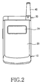
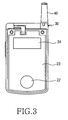
- As illustrated in FIG. 1, FIG 2 and FIG.3, a folder-type portable terminal comprises a
main body 10 having a plurality ofkeys 11 which are pressed to enter intended data and amicrophone 12, afolder 20 having amain LCD 21, asub LCD 24 for displaying input data, aspeaker 22, aPCB 23 in thefolder 20 and ahinge device 30 which connects thebody 10 and thefolder 20 along a hinge axis A1 and is rotatable so that thefolder 20 advances toward or recedes away from thebody 10. - Traditionally, the width of the
folder 20 is relatively made wide as compared to its length, or the hinge axis A1 is defined near anantenna device 40 on themain body 10, for sake of fabrication convenience. - Therefore, electromagnetic waves from a power supply for the antenna can leak in the
hinge device 30, which is positioned between themain body 10 and thefolder 20, thereby increasing SAR. - Moreover, if the antenna is a monopole antenna, a ground surface perpendicular to an antenna element is needed within an upper portion of the
main body 10. However, due to thehinge device 30, a sufficient antenna ground area is difficult to ensure and reduction of the thickness of the portable terminal is limited. - Meanwhile, a SAR-reducing folder-type terminal has been developed. It has the same configuration as the conventional folder-type portable terminal, except that an electromagnetic wave reflecting plate is attached on the inner or outer surface of the
folder 20 such that it faces the antenna device when thefolder 20 is opened. - In this case, the antenna can be a helical antenna, a whip antenna, or a half-exposed, fixed monopole antenna. Use the half-exposed, fixed monopole antenna, allows the antenna ground surface to be easily obtained by the reflecting plate. If the antenna ground surface must be secured on the upper surface of the main body by using the whip or helical antenna, the ground surface itself will be narrow.
- Folder-type portable terminals typically have a ground larger than 1/4λ of its operating frequency, e.g. 1800MHz. The ground refers to a part of the main body or folder where electrical current flows. Depending upon the current distribution of the folder, a radiation pattern can greatly vary. Because there is no specific solutions for SAR reduction, SAR, reduction, attempts have been made to reduce SAR by lowering antenna output, thereby deteriorating the operation characteristics of the antenna device.
- WO 02/071534 refers to a radio communications device comprising an SAR value reducing correction element. The radio communications device has at least one additional SAR value reducing correction element provided in and/or on a housing in such a manner that the distribution of any electric current which might be flowing on a printed circuit board is effected form one or more local maxima thereof up to the correction element. It has been found, that in principle, there are two options for reducing specific SAR value. A first option is to move the respective current maximum away from an absorption point. A second option is to reduce the current maximum by a distribution by means of equalizing currents. An electrically conductive element used is a single or multilayer, electrically conductive film, coating or another electrically conductive surface element. The correction element is in contact with the earth of the printed circuit board only at a single, electrical and mechanical contact point. This contact allows some of the electric current to be diverted from the printed circuit board to the correction element. It can also be adequate for homogenization of the current field taken over the overall cross section (printed circuit board plus correction element) of the mobile radio device for just two separate stripes to be attached as an additional correction element. Unlike the correction elements discussed above, another possibility is to use a wire that is housed between the upper casing and the printed circuit board as and additional, SAR value reducing correction element. This wire is expediently configured so that the one or more maxima of the local current field on the printed circuit board can largely be equalized, so that, taken over the cross section, homogenization of the current amplitude results. Further, a conductor can be provided as a SAR value reducing correction element and this is, for example, curved into an L-shape. This has contact with a to the earth of the printed circuit board.
- An aspect of the present invention is to substantially solve at least the above problems and/or disadvantages and to provide at least the advantages below.
- Accordingly, it is another aspect of the present invention to provide a portable terminal having a tuner configured for changing an antenna radiation pattern by changing the current distribution of a ground, thereby reducing SAR and improving antenna operation characteristics.
- It is the object of the present invention to provide an improved portable terminal having reduced SAR and improved antenna operation characteristics.
- This object is solved by the subject matter of the independent claims.
- Preferred embodiments are defined in the dependent claims.
- According to one aspect of the present invention, in a portable terminal, a main body of the terminal has a main body PCB and a main body ground defined in the main body PCB. A folder is rotatably connected to the main body by a hinge device. An antenna device is provided at an upper end of the main body. A tuner is formed at a predetermined position of the main body in the vicinity of the antenna device, for changing a current distribution of the main body and thus changing an antenna radiation pattern of the portable terminal.
- According to another aspect of the present invention, in a portable terminal, a folder has a folder PCB and a folder ground denned in the folder PCB. The folder is rotatably connected to a main body by a hinge device. An antenna device is provided at an upper end of the main body. A tuner is formed at a predetermined position of the folder in the vicinity of the antenna device, for changing a current distribution of the main body and thus changing an antenna radiation pattern of the portable terminal.
- According to a further aspect of the present invention, in a portable terminal, a main body has side hinge arms at both upper ends thereof, a folder has a center hinge arm rotatably connected between the side hinge arms and hinged to the main body, an antenna device protrudes from an upper end of the main body, and a tuner is formed into a predetermined pattern in the center hinge arm, for changing a radiation pattern of the antenna device.
- The above features and advantages of the present invention will become more apparent from the following detailed description when taken in conjunction with the accompanying drawings in which:
- FIG. 1 is a perspective view illustrating a conventional folder-type portable terminal in an open state;
- FIG. 2 is a plan view of a the conventional folder-type portable terminal in a closed state;
- FIG. 3 is a view of the interior structure of a folder in the conventional folder-type portable terminal illustrated in FIG 2;
- FIG. 4 is a graph illustrating the azimuth radiation pattern of the conventional folder-type portable terminal illustrated in FIG 1;
- FIG 5 is a graph illustrating an elevation (E1) radiation pattern of the conventional folder-type portable terminal illustrated in FIG 1;
- FIG. 6 is a graph illustrating an elevation (E2) radiation pattern of the conventional folder-type portable terminal illustrated in FIG 1;
- FIG 7 is a view of the interior structure of the main body showing a preferred embodiment of the present invention;
- FIG 8 is an enlarged view of a portion "A" illustrated in FIG 7;
- FIG 9 is a side sectional view illustrating an embodiment of a tuner mounted on a main body PCB (Printed Circuit Board) in the main body of the portable terminal illustrated in FIG 7;
- FIG 10 is a side sectional view illustrating another embodiment of a tuner mounted under the main body PCB in the main body of the portable terminal illustrated in FIG 7;
- FIG 11 is a view of the interior structure of the main body showing another embodiment of the pattern of the tuner;
- FIG 12 illustrates another pattern of the tuner in the main body of the portable terminal illustrated in FIG 7;
- FIG 13 is a graph illustrating the azimuth radiation pattern of the portable terminal illustrated in FIG 7;
- FIG 14 is a graph illustrating an E1 radiation pattern of the portable terminal illustrated in FIG 7;
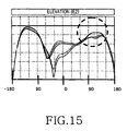
- FIG 15 is a graph illustrating an E2 radiation pattern of the portable terminal illustrated in FIG 7;
- FIG 16 illustrates the interior structure of a folder of a portable terminal having a tuner pattern according to another preferred embodiment of the present invention;
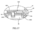
- FIG. 17 is an enlarged view of a portion "B" illustrated in FIG 16;
- FIG 18 is an exploded perspective view illustrating the folder of the portable terminal illustrated in FIG 16;
- FIG 19 illustrates an alternative pattern of a tuner in the folder of the portable terminal illustrated in FIG 16;
- FIG 20 illustrates another pattern of the tuner in the folder of the portable terminal illustrated in FIG 16;
- FIG 21 is a graph illustrating the azimuth radiation pattern of the portable terminal illustrated in FIG 16;
- FIG. 22 is a graph illustrating an E1 radiation pattern of the portable terminal illustrated in FIG 16; and
- FIG 23 is a graph illustrating an E2 radiation pattern of the portable terminal illustrated in FIG 16.
- Preferred embodiments of the present invention will be described herein below with reference to the accompanying drawings. In the following description, well-known functions or constructions are not described in detail since they would obscure the invention in unnecessary detail.
- Referring to FIGs. 7 to 23, portable terminals according to two preferred embodiments of the present invention comprise the
main body 10 having aPCB 13 and aground 400 defined in thePCB 13, and thefolder 20 having aPCB 23 and aground 4000 defined in thePCB 23. Thehinge device 30 is provided at an end of themain body 10, for connecting themain body 10 to thefolder 20. Theantenna device 40 is installed at an appropriate position on an upper end of themain body 10. - Referring to FIGs. 7 to 15, in the portable terminal according to a first preferred embodiment of the present invention, a
tuner 100 is disposed within themain body 10, in the vicinity of theantenna device 40, for concurrently changing the current distribution of themain body ground 400 and the antenna radiation pattern of themain body 10. - The
tuner 100 preferably has an "F" or a "P" shape. Thetuner 100 is provided, at anend 101 thereof, with a connector 3 00 that comes into contact with agrounding portion 13a of themain body ground 400. Theother end 102 of thetuner 100 is remote, i.e. positioned away, from the groundingportion 13a and is positioned in the end ofmain body 10 to closest to theantenna device 40. - The
tuner 100 can be formed in a predetermined pattern using a conductive paint so that it is easily connected to thegrounding portion 13a of themain body ground 400. Also, thetuner 100 may be formed of a metal to easily change the current distribution of themain body ground 400. - As illustrated in FIGS. 9 and 10, the
tuner 100 is provided on the top surface or bottom surface of themain body PCB 13. The top or bottom surfaces of themain body PCB 13 respectively correspond to the surface that is away from or closer to theantenna 40. - The
tuner 100 changes the current distribution of themain body ground 400 and thus changes the antenna radiation pattern of the terminal. At the same time, thetuner 100 reduces SAR and improves antenna operation characteristics, i.e. field performance. Tuning can be carried out such that the antenna radiation pattern is changed by controlling the pattern of thetuner 100, that is, the length or structure of thetuner 100. - As illustrated in FIGs. 11 and 12, the
tuner 100 can be formed in a "P" shape or an "F" shape, respectively. - Referring to FIG. 12, an F-shaped
tuner 200 is provided, atend 201 thereof, with theconnector 300. The other twoends 202 of thetuner 200 are extended in parallel with each other along the length of thehinge device 30 such that they are remote, i.e. positioned away, from the groundingportion 13a and are positioned in the same end ofmain body 10 as theantenna device 40. - FIG. 13 is a graph illustrating an azimuth radiation pattern of the portable terminal having the
tuner 100 according to the embodiment of the present invention. The direction of zero degrees (0°) indicated on the abscissa is a direction toward the user's head. Comparison with the azimuth radiation pattern of the conventional portable terminals which lack a tuner, as illustrated in FIG 4, reveals that the portable terminal having thetuner 100 radiates less electromagnetic energy toward the human body. - FIGs. 14 and 15 are graphs illustrating elevations E1 and E2 radiation patterns of the portable terminal with the
tuner 100 according to the first embodiment of the present invention. A range between of 90 to 150° in the elevation patterns corresponds to the direction toward the human body. Comparison with the E1 and E2 radiation patterns of the conventional portable terminals which lack a tuner, as illustrated in FIGs. 5 and 6, reveals that portable terminals having thetuner 100 radiate less electromagnetic energy toward the human body. - With reference to FIGs. 16 to 23, the operation of a portable terminal having a tuner for changing a radiation pattern according to another preferred embodiment of the present invention will be described below.
- As illustrated in FIGs. 16 and 17, the portable terminal comprises a
tuner 1000 positioned at an end of thefolder 20. - The
tuner 1000 changes the current distribution of afolder ground 4000 defined in thefolder 20 and thus changes the antenna radiation pattern of the terminal. At the same time, it reduces SAR and improves field performance. - The
tuner 1000 is preferably disposed in the vicinity of theantenna 40. Thetuner 1000 is provided, at anend 1001 thereof, with aconnector 3000 that comes into contact with agrounding portion 23a of thefolder ground 4000 defined on the antenna frame or thefolder PCB 23. Theother end 1002 of thetuner 1000 is disposed remote from the groundingportion 23a and is positioned in the end offolder 20 closest to theantenna device 40. The length or structure of thetuner 1000 is adjusted depending on the change of the antenna radiation pattern. - FIG 18 is an exploded perspective view illustrating the
tuner 1000 illustrated in FIG. 16 mounted on thefolder 20. Thetuner 1000 is formed into a predetermined pattern within acenter hinge arm 35 formed at an end of thefolder 20. - The
folder 20 is provided with afront case 20a and arear case 20b attached to the rear of thefront case 20a. Thefront case 20a faces themain body 10 when thefolder 20 is hingeably closed to themain body 10. Thefront case 20a is provided, at an end thereof, with thecenter hinge arm 35. An outer circumferential portion of thecenter hinge arm 35 is covered with therear case 20b. - Preferably, the
tuner 1000 is positioned within thecenter hinge arm 35 and, more specifically, extends along the hinge axis A1 at the outer circumferential portion of thecenter hinge arm 35, which is covered with therear case 20b. While thetuner 1000 is preferably formed by coating a portion of thecenter hinge arm 35 of thefolder 20 with a conductive paint, alternative embodiments of the present invention can utilize a conductive cloth tape or an attachable metal pattern. Thetuner 1000 is preferably connected to a ground line of thefolder PCB 23 or to a conductive spray coated in thefolder 20. - The
tuner 1000 having the above-described configuration expands the grounding of the PCB and changes the radiation pattern of the antenna device, thereby reducing SAR. - As illustrated in FIGs. 19 and 20, the
tuner 1000 preferably has an "F" or a "P" shape. - Referring to FIG 20, an F-shaped
tuner 2000 is provided, atend 2001 thereof, with theconnector 3000. The other twoends 2002 of thetuner 2000 are extended in parallel with each other along the length of thehinge device 30 such that they are remote from the groundingportion 23 a and near to theantenna device 40. - FIG. 21 is a graph illustrating an azimuth radiation pattern of the portable terminal having the
tuner 1000 according to the second embodiment of the present invention. The direction of zero degrees (0°) shown on the abscissa is a direction toward the user's head. Comparison with the azimuth radiation pattern of the conventional portable terminals which lack a tuner, as illustrated in FIG 4, reveals that portable terminals having thetuner 1000 radiate less electromagnetic energy toward the human body. - FIGs. 22 and 23 are graphs illustrating elevations E1 and E2 radiation patterns of the portable terminal with the
tuner 1000 according to the second embodiment of the present invention. A range between of 90 to 150° in the elevation patterns corresponds to the direction toward the user's body. Comparison with the E1 and E2 radiation patterns of the conventional portable terminals which lack a tuner, as illustrated in FIGs. 5 and 6, reveals that portable terminals having thetuner 1000 radiate less electromagnetic energy toward the user's body. - By configuring the tuner 100 (or 1000) so as to change the current distribution of the
main body 10 and thefolder 20 and thus change the antenna radiation pattern, the current distribution of the terminal and the antenna radiation pattern can be changed to meet a required specification. The resulting SAR reduction and improvement of field operation performance improve the antenna performance of the terminal. - In accordance with the present invention as described above, the tuner is positioned in the vicinity of the antenna device to change the current distribution of the ground current in the folder and thus change an antenna radiation pattern. Therefore, SAR is reduced and field operation performance is improved, thereby improving the antenna performance of the terminal.
- While the invention has been shown and described with reference to certain preferred embodiments thereof, they are mere exemplary applications. For example, the present invention is not limited to a folder-type terminal. It is applicable to any type of portable terminal. Thus, it will be understood by those skilled in the art that various changes in form and details may be made therein without departing from the scope of the invention as defined by the appended claims.
Claims (15)
- A portable terminal comprising:a main body (10) having a main body printed circuit board (13) and a main body ground (400) defined in the main body printed circuit board (13),a folder (20);a hinge device (30) for rotatably connecting the main body (10) to the folder (20);an antenna device (40) provided at an end of the main body (10) closest to the hinge device (30); anda current distribution element (100, 200)characterized in that the current distribution element is positioned in the main body (10) in a room between an end of the main body printed circuit board (13) and an end of the main body (10) towards the antenna device (40) and in the vicinity of the antenna device (40).
- A portable terminal comprising:a main body (10);a folder (20) having a folder printed circuit board (23) and a folder ground (4000) defined in the folder printed circuit board (23);a hinge device (30) for rotatably connecting the main body (10) to the folder (20);an antenna device (40) provided at an end of the main body (10) closest to the hinge device (30); anda current distribution element (1000)
characterized in that the current distribution element is positioned in the folder (20) in a room between an end of the folder printed circuit board (23) and an end of the folder (20) towards the antenna device (40) and in the vicinity of the antenna device (40). - The portable terminal of claim 1 or 2, wherein the current distribution element (100, 200, 1000) has an "F" or a "P" shape.
- The portable terminal of claim 1, wherein the current distribution element (100, 200) includes, at an end (101) thereof, a connector (300) for contacting a grounding portion (13a) of the main body ground (400) and another end (102) of the current distribution element (100, 200) is remote from the grounding portion (13a) and near the antenna device (40).
- The portable terminal of claim 2, wherein the current distribution element (1000) includes, at an end (1001) thereof, a connector (3000) for contacting a grounding portion (23a) of the folder ground (4000) and another end (1002) of the current distribution element (1000) is remote from the grounding portion (23a) and near the antenna device (40).
- The portable terminal of one of claims 1 to 5, wherein the current distribution element (100, 200, 1000) is formed of a conductive paint.
- The portable terminal of one of claims 1 to 6, wherein the current distribution element (100, 200, 1000) is formed of a metal.
- The portable terminal of claim 1 or 4, wherein the current distribution element (100, 200) is connected with the main body ground (400).
- The portable terminal of claim 2 or 5, wherein the current distribution element (1000) is connected with the folder ground (4000).
- The portable terminal of claim 1, wherein the current distribution element (100, 200) is formed on an upper surface or a lower surface of the main body printed circuit board (13).
- A portable terminal comprising:a main body (10) having side hinge arms at both sides of an upper end thereof;a folder (20) having a center hinge arm (35) rotatably connected between the side hinge arms for hingably connecting the folder (20) to the main body (10);an antenna device (40) protruding from the upper end of the main body (10); anda current distribution element (2000)
characterized in that the current distribution element is positioned in the center hinge arm (35). - The portable terminal of claim 11, wherein the folder (20) comprises:a front case (20a) facing the main body (10) when the folder (20) is closed toward the main body (10); anda rear case (20b) attached to the rear of the front case (20a),wherein the center hinge arm (35) is installed at an end of the front case (20a) and the current distribution element (2000) is covered with the rear case (20b).
- The portable terminal of claim 11 or 12, wherein the current distribution element (2000) is formed in a pattern which extends along the length of the center hinge arm (35).
- The portable terminal of claim 11 or 12, wherein the current distribution element (2000) is a conductive tape.
- The portable terminal of claim 11 or 12, wherein the current distribution element (2000) is formed by coating a portion of the center hinge arm (35) with a conductive paint.
Applications Claiming Priority (6)
| Application Number | Priority Date | Filing Date | Title |
|---|---|---|---|
| KR2003033198 | 2003-05-24 | ||
| KR20030033198 | 2003-05-24 | ||
| KR20030052625 | 2003-07-30 | ||
| KR2003052625 | 2003-07-30 | ||
| KR1020030087754A KR100584399B1 (en) | 2003-05-24 | 2003-12-04 | Portable terminal with tuning apparatus for changing radiation pattern |
| KR2003087754 | 2003-12-04 |
Publications (3)
| Publication Number | Publication Date |
|---|---|
| EP1482646A2 EP1482646A2 (en) | 2004-12-01 |
| EP1482646A3 EP1482646A3 (en) | 2005-03-02 |
| EP1482646B1 true EP1482646B1 (en) | 2007-03-07 |
Family
ID=33135784
Family Applications (1)
| Application Number | Title | Priority Date | Filing Date |
|---|---|---|---|
| EP04012115A Expired - Lifetime EP1482646B1 (en) | 2003-05-24 | 2004-05-21 | Portable terminal having tuner for changing radiation pattern |
Country Status (4)
| Country | Link |
|---|---|
| US (1) | US7280856B2 (en) |
| EP (1) | EP1482646B1 (en) |
| CN (1) | CN1574661A (en) |
| DE (1) | DE602004005101T2 (en) |
Families Citing this family (31)
| Publication number | Priority date | Publication date | Assignee | Title |
|---|---|---|---|---|
| US8744384B2 (en) | 2000-07-20 | 2014-06-03 | Blackberry Limited | Tunable microwave devices with auto-adjusting matching circuit |
| KR100539935B1 (en) * | 2003-08-08 | 2005-12-28 | 삼성전자주식회사 | Ground connecting apparatus for mobile phone |
| GB2423643A (en) * | 2003-12-09 | 2006-08-30 | Matsushita Electric Co Ltd | Folding mobile radio device |
| US20050282595A1 (en) * | 2004-06-21 | 2005-12-22 | Spence Michael F | Communication device including one or more electrical control buttons in an upper housing part |
| US9406444B2 (en) | 2005-11-14 | 2016-08-02 | Blackberry Limited | Thin film capacitors |
| CN1988252B (en) * | 2005-12-19 | 2011-05-11 | 环旭电子股份有限公司 | Printed folding antenna |
| US7711337B2 (en) | 2006-01-14 | 2010-05-04 | Paratek Microwave, Inc. | Adaptive impedance matching module (AIMM) control architectures |
| KR100722309B1 (en) * | 2006-01-20 | 2007-05-28 | 삼성전자주식회사 | Electromagnetic wave absorption rate reduction device and mobile communication terminal including the device |
| USD554094S1 (en) * | 2006-03-31 | 2007-10-30 | Motorola, Inc. | Housing for a communication device |
| KR100842081B1 (en) * | 2006-07-26 | 2008-06-30 | 삼성전자주식회사 | Monopole antenna with increased bandwidth and mobile communication terminal with same |
| US7714676B2 (en) | 2006-11-08 | 2010-05-11 | Paratek Microwave, Inc. | Adaptive impedance matching apparatus, system and method |
| US7535312B2 (en) | 2006-11-08 | 2009-05-19 | Paratek Microwave, Inc. | Adaptive impedance matching apparatus, system and method with improved dynamic range |
| US7917104B2 (en) | 2007-04-23 | 2011-03-29 | Paratek Microwave, Inc. | Techniques for improved adaptive impedance matching |
| US7991363B2 (en) | 2007-11-14 | 2011-08-02 | Paratek Microwave, Inc. | Tuning matching circuits for transmitter and receiver bands as a function of transmitter metrics |
| US8072285B2 (en) | 2008-09-24 | 2011-12-06 | Paratek Microwave, Inc. | Methods for tuning an adaptive impedance matching network with a look-up table |
| US9026062B2 (en) * | 2009-10-10 | 2015-05-05 | Blackberry Limited | Method and apparatus for managing operations of a communication device |
| US8803631B2 (en) | 2010-03-22 | 2014-08-12 | Blackberry Limited | Method and apparatus for adapting a variable impedance network |
| CN101867384B (en) * | 2010-04-12 | 2015-04-01 | 中兴通讯股份有限公司 | Wireless terminal for reducing specific absorption rate peak and realization method thereof |
| CA2797074C (en) | 2010-04-20 | 2018-08-14 | Research In Motion Rf, Inc. | Method and apparatus for managing interference in a communication device |
| CN101867385B (en) | 2010-06-21 | 2013-11-06 | 华为终端有限公司 | wireless communication equipment |
| US8712340B2 (en) | 2011-02-18 | 2014-04-29 | Blackberry Limited | Method and apparatus for radio antenna frequency tuning |
| US8655286B2 (en) | 2011-02-25 | 2014-02-18 | Blackberry Limited | Method and apparatus for tuning a communication device |
| US8594584B2 (en) | 2011-05-16 | 2013-11-26 | Blackberry Limited | Method and apparatus for tuning a communication device |
| WO2013022826A1 (en) | 2011-08-05 | 2013-02-14 | Research In Motion Rf, Inc. | Method and apparatus for band tuning in a communication device |
| CN103428903B (en) | 2012-05-16 | 2016-12-21 | 华为终端有限公司 | Wireless Telecom Equipment and the method manufacturing Wireless Telecom Equipment |
| US8948889B2 (en) | 2012-06-01 | 2015-02-03 | Blackberry Limited | Methods and apparatus for tuning circuit components of a communication device |
| US9853363B2 (en) | 2012-07-06 | 2017-12-26 | Blackberry Limited | Methods and apparatus to control mutual coupling between antennas |
| US9350405B2 (en) | 2012-07-19 | 2016-05-24 | Blackberry Limited | Method and apparatus for antenna tuning and power consumption management in a communication device |
| US10404295B2 (en) | 2012-12-21 | 2019-09-03 | Blackberry Limited | Method and apparatus for adjusting the timing of radio antenna tuning |
| US9374113B2 (en) | 2012-12-21 | 2016-06-21 | Blackberry Limited | Method and apparatus for adjusting the timing of radio antenna tuning |
| US9438319B2 (en) | 2014-12-16 | 2016-09-06 | Blackberry Limited | Method and apparatus for antenna selection |
Family Cites Families (16)
| Publication number | Priority date | Publication date | Assignee | Title |
|---|---|---|---|---|
| SE508365C2 (en) * | 1996-11-04 | 1998-09-28 | Ericsson Telefon Ab L M | Radio telephone with high antenna efficiency |
| SE9801381D0 (en) * | 1998-04-20 | 1998-04-20 | Allgon Ab | Ground extension arrangement for coupling to ground means in an antenna system, and an antenna system and a mobile radio device having such ground arrangement |
| KR100342510B1 (en) * | 2000-01-17 | 2002-06-28 | 윤종용 | Flip-type terminal with slim-type microstrip patch antenna for gps |
| US6246374B1 (en) * | 2000-04-06 | 2001-06-12 | Motorola, Inc. | Passive flip radiator for antenna enhancement |
| US6885880B1 (en) * | 2000-09-22 | 2005-04-26 | Teleponaktiebolaget Lm Ericsson (Publ.) | Inverted-F antenna for flip-style mobile terminals |
| US7031762B2 (en) * | 2000-12-28 | 2006-04-18 | Mitsubishi Denki Kabushiki Kaisha | Mobile terminal including first and second housings and an antenna |
| KR100381139B1 (en) | 2001-01-17 | 2003-04-18 | 삼성전자주식회사 | Method for displaying message in folder type mobile terminal |
| EP1368856A1 (en) | 2001-03-07 | 2003-12-10 | Siemens Aktiengesellschaft | Radio communications device comprising an sar value-reducing correction element |
| DE10134848C1 (en) | 2001-07-17 | 2002-12-12 | Siemens Ag | Reduced-SAR mobile radio transceiver, e.g. portable telephone, has an electrically conductive layer to interact with devices in a transmit-receive mode to generate a field of scattered EM waves |
| JP2003101335A (en) * | 2001-09-25 | 2003-04-04 | Matsushita Electric Ind Co Ltd | Antenna device and communication device using the same |
| KR100593984B1 (en) * | 2002-01-18 | 2006-06-30 | 삼성전자주식회사 | Antenna device using hinge spring |
| KR100652620B1 (en) * | 2003-07-30 | 2006-12-06 | 엘지전자 주식회사 | Portable terminal with built-in antenna |
| KR100539935B1 (en) * | 2003-08-08 | 2005-12-28 | 삼성전자주식회사 | Ground connecting apparatus for mobile phone |
| JP2005244260A (en) * | 2003-12-24 | 2005-09-08 | Toshiba Corp | Portable wireless terminal |
| KR100619695B1 (en) * | 2004-06-23 | 2006-09-08 | 엘지전자 주식회사 | Antenna and portable terminal with same |
| US7554494B2 (en) * | 2004-10-21 | 2009-06-30 | Samsung Electronics Co., Ltd. | Built-in antenna module in portable wireless terminal |
-
2004
- 2004-04-29 US US10/834,737 patent/US7280856B2/en not_active Expired - Lifetime
- 2004-05-21 EP EP04012115A patent/EP1482646B1/en not_active Expired - Lifetime
- 2004-05-21 DE DE602004005101T patent/DE602004005101T2/en not_active Expired - Lifetime
- 2004-05-24 CN CN200410045337.0A patent/CN1574661A/en active Pending
Also Published As
| Publication number | Publication date |
|---|---|
| DE602004005101T2 (en) | 2007-12-13 |
| EP1482646A3 (en) | 2005-03-02 |
| US7280856B2 (en) | 2007-10-09 |
| US20040204027A1 (en) | 2004-10-14 |
| DE602004005101D1 (en) | 2007-04-19 |
| EP1482646A2 (en) | 2004-12-01 |
| CN1574661A (en) | 2005-02-02 |
Similar Documents
| Publication | Publication Date | Title |
|---|---|---|
| US7280856B2 (en) | Portable terminal having tuner for changing radiation pattern | |
| JP4358084B2 (en) | Foldable portable radio | |
| US5945954A (en) | Antenna assembly for telecommunication devices | |
| JP4242780B2 (en) | Balanced multiband antenna device | |
| US6590539B2 (en) | Antenna device in radio communication terminal | |
| JP4850839B2 (en) | Portable radio | |
| EP1505800B1 (en) | Ground connecting apparatus for the foldable mobile terminal | |
| JP2004104419A (en) | Antenna for portable radio | |
| US7225004B2 (en) | Mobile communication terminal | |
| JP2005094501A (en) | Planar multiple antenna | |
| EP1962372B1 (en) | Miniature broadband antenna with inductive chassis coupling | |
| JP4189433B1 (en) | Portable radio | |
| KR100689475B1 (en) | Built-in antenna device of mobile terminal | |
| US7398113B2 (en) | Portable wireless apparatus | |
| US20040162122A1 (en) | Antenna structure for reducing effects on the human body of electromagnetic waves from mobile communication terminal | |
| EP2234203B1 (en) | Mobile apparatus | |
| KR20010052177A (en) | Substrate antenna | |
| EP1646108B1 (en) | Antenna module for portable wireless terminal | |
| JPH1155148A (en) | Portable wireless devices | |
| KR100584399B1 (en) | Portable terminal with tuning apparatus for changing radiation pattern | |
| KR100343529B1 (en) | Dipole antenna for arranging in an interior of a terminal for wireless data communication | |
| JP3960191B2 (en) | ANTENNA AND ELECTRIC DEVICE HAVING THE SAME | |
| CN119921096A (en) | Antenna enhancement accessories and communication systems | |
| KR100667149B1 (en) | Broadband station f antenna |
Legal Events
| Date | Code | Title | Description |
|---|---|---|---|
| PUAI | Public reference made under article 153(3) epc to a published international application that has entered the european phase |
Free format text: ORIGINAL CODE: 0009012 |
|
| 17P | Request for examination filed |
Effective date: 20040521 |
|
| AK | Designated contracting states |
Kind code of ref document: A2 Designated state(s): AT BE BG CH CY CZ DE DK EE ES FI FR GB GR HU IE IT LI LU MC NL PL PT RO SE SI SK TR |
|
| AX | Request for extension of the european patent |
Extension state: AL HR LT LV MK |
|
| PUAL | Search report despatched |
Free format text: ORIGINAL CODE: 0009013 |
|
| AK | Designated contracting states |
Kind code of ref document: A3 Designated state(s): AT BE BG CH CY CZ DE DK EE ES FI FR GB GR HU IE IT LI LU MC NL PL PT RO SE SI SK TR |
|
| AX | Request for extension of the european patent |
Extension state: AL HR LT LV MK |
|
| AKX | Designation fees paid |
Designated state(s): DE FR GB |
|
| GRAP | Despatch of communication of intention to grant a patent |
Free format text: ORIGINAL CODE: EPIDOSNIGR1 |
|
| GRAS | Grant fee paid |
Free format text: ORIGINAL CODE: EPIDOSNIGR3 |
|
| GRAA | (expected) grant |
Free format text: ORIGINAL CODE: 0009210 |
|
| AK | Designated contracting states |
Kind code of ref document: B1 Designated state(s): DE FR GB |
|
| REG | Reference to a national code |
Ref country code: GB Ref legal event code: FG4D |
|
| REF | Corresponds to: |
Ref document number: 602004005101 Country of ref document: DE Date of ref document: 20070419 Kind code of ref document: P |
|
| PLBE | No opposition filed within time limit |
Free format text: ORIGINAL CODE: 0009261 |
|
| STAA | Information on the status of an ep patent application or granted ep patent |
Free format text: STATUS: NO OPPOSITION FILED WITHIN TIME LIMIT |
|
| 26N | No opposition filed |
Effective date: 20071210 |
|
| REG | Reference to a national code |
Ref country code: FR Ref legal event code: PLFP Year of fee payment: 13 |
|
| REG | Reference to a national code |
Ref country code: FR Ref legal event code: PLFP Year of fee payment: 14 |
|
| PGFP | Annual fee paid to national office [announced via postgrant information from national office to epo] |
Ref country code: GB Payment date: 20170420 Year of fee payment: 14 Ref country code: FR Payment date: 20170516 Year of fee payment: 14 |
|
| PGFP | Annual fee paid to national office [announced via postgrant information from national office to epo] |
Ref country code: DE Payment date: 20170621 Year of fee payment: 14 |
|
| REG | Reference to a national code |
Ref country code: DE Ref legal event code: R119 Ref document number: 602004005101 Country of ref document: DE |
|
| GBPC | Gb: european patent ceased through non-payment of renewal fee |
Effective date: 20180521 |
|
| PG25 | Lapsed in a contracting state [announced via postgrant information from national office to epo] |
Ref country code: GB Free format text: LAPSE BECAUSE OF NON-PAYMENT OF DUE FEES Effective date: 20180521 Ref country code: FR Free format text: LAPSE BECAUSE OF NON-PAYMENT OF DUE FEES Effective date: 20180531 Ref country code: DE Free format text: LAPSE BECAUSE OF NON-PAYMENT OF DUE FEES Effective date: 20181201 |