EP1482634A2 - Motor drive system - Google Patents
Motor drive system Download PDFInfo
- Publication number
- EP1482634A2 EP1482634A2 EP04253086A EP04253086A EP1482634A2 EP 1482634 A2 EP1482634 A2 EP 1482634A2 EP 04253086 A EP04253086 A EP 04253086A EP 04253086 A EP04253086 A EP 04253086A EP 1482634 A2 EP1482634 A2 EP 1482634A2
- Authority
- EP
- European Patent Office
- Prior art keywords
- motor drive
- overcurrent detection
- power supply
- amplifiers
- overcurrent
- Prior art date
- Legal status (The legal status is an assumption and is not a legal conclusion. Google has not performed a legal analysis and makes no representation as to the accuracy of the status listed.)
- Withdrawn
Links
Images

Classifications
-
- H—ELECTRICITY
- H02—GENERATION; CONVERSION OR DISTRIBUTION OF ELECTRIC POWER
- H02H—EMERGENCY PROTECTIVE CIRCUIT ARRANGEMENTS
- H02H7/00—Emergency protective circuit arrangements specially adapted for specific types of electric machines or apparatus or for sectionalised protection of cable or line systems, and effecting automatic switching in the event of an undesired change from normal working conditions
- H02H7/08—Emergency protective circuit arrangements specially adapted for specific types of electric machines or apparatus or for sectionalised protection of cable or line systems, and effecting automatic switching in the event of an undesired change from normal working conditions for dynamo-electric motors
- H02H7/0833—Emergency protective circuit arrangements specially adapted for specific types of electric machines or apparatus or for sectionalised protection of cable or line systems, and effecting automatic switching in the event of an undesired change from normal working conditions for dynamo-electric motors for electric motors with control arrangements
-
- H—ELECTRICITY
- H02—GENERATION; CONVERSION OR DISTRIBUTION OF ELECTRIC POWER
- H02P—CONTROL OR REGULATION OF ELECTRIC MOTORS, ELECTRIC GENERATORS OR DYNAMO-ELECTRIC CONVERTERS; CONTROLLING TRANSFORMERS, REACTORS OR CHOKE COILS
- H02P5/00—Arrangements specially adapted for regulating or controlling the speed or torque of two or more electric motors
- H02P5/74—Arrangements specially adapted for regulating or controlling the speed or torque of two or more electric motors controlling two or more AC dynamo-electric motors
-
- H—ELECTRICITY
- H02—GENERATION; CONVERSION OR DISTRIBUTION OF ELECTRIC POWER
- H02M—APPARATUS FOR CONVERSION BETWEEN AC AND AC, BETWEEN AC AND DC, OR BETWEEN DC AND DC, AND FOR USE WITH MAINS OR SIMILAR POWER SUPPLY SYSTEMS; CONVERSION OF DC OR AC INPUT POWER INTO SURGE OUTPUT POWER; CONTROL OR REGULATION THEREOF
- H02M1/00—Details of apparatus for conversion
- H02M1/32—Means for protecting converters other than automatic disconnection
Definitions
- the present invention relates to a motor drive system in which a plurality of motor drive amplifiers are connected to one motor drive power supply to thereby drive respective motors.
- a motor drive system in which a plurality of motor drive amplifiers for driving motors, respectively, are connected to a motor drive power supply to thereby supply a power to the respective motor drive amplifiers from one motor drive power supply, and in which the motor drive power supply is shared among the amplifiers.
- overcurrent detection values currents to be detected as an overcurrent
- overcurrent detection means for detecting overcurrent, corresponding to the number of the motor drive amplifiers connectable to the motor drive power supply.
- overcurrent detection means for detecting the overcurrent by detecting a current flowing in the motor drive power supply, corresponding to the maximum number of motor drive amplifiers connectable to the motor driver power supply, in case where a smaller number of motor drive amplifiers than the maximum number of connectable motor drive amplifiers are connected to the motor drive power supply, if an overcurrent actually occurs to one of the motor drive amplifiers, then occurrence of the overcurrent cannot be detected, with the result that an excessive energy is supplied to a portion in which the overcurrent occurs. In consequence, components located in the portion may possibly be broken, and damages such as smoke emission and ignition may possibly occur to the components.
- the present invention relates to a motor drive system which comprises a motor drive power supply and a plurality of motor drive amplifiers connected to the motor drive power supply, and drives motors by the respective motor drive amplifiers.
- the motor drive system further comprises overcurrent detectionmeans for detecting a current flowing in the motor drive power supply, wherein an overcurrent detection value detected as an overcurrent by the overcurrent detection means can be changed.
- the motor drive amplifiers comprise memories that store specifications of the respective motor drive amplifiers.
- the motor drive system further comprises: means for reading storage contents of the memories; overcurrent detection value storage means for storing overcurrent detection values corresponding to the specifications of the respective motor drive amplifiers; and means for reading the overcurrent detection values from the overcurrent detection value storage means based on the specifications read from the respective memories, and then integrating the overcurrent detection values.
- An integrated value of the overcurrent detection values of the plurality of motor drive amplifiers connected to the motor drive power supply is a value to be detected by the overcurrent detection means.
- Fig. 1 is a block diagram of a motor drive system according to one embodiment of the present invention.
- reference numeral 1 denotes a motor drive controller such as a numeric control device
- reference numeral 2 denotes a power supply units
- reference symbols 3a and 3b denote motor drive amplifiers
- reference symbols 4a and 4b denote motors.
- the motor drive controller 1 is connected to control circuits 31a and 31b for controlling inverter circuits 33a and 33b provided in the motor drive amplifiers 3a and 3b, respectively, by daisy chaining.
- the inverter circuits 33a and 33b in the respective motor drive amplifiers 3a and 3b are connected to a motor drive power supply 6 provided in the power supply unit 2.
- a drive power line is indicated by a solid line
- a control signal line is indicated by a broken line.
- the power supply unit 2 includes a power supply unit control circuit 5.
- the power supply unit control circuit 5 includes a microcontroller 51, a memory 52 connected to the microcontroller 51, and a control circuit 53 connected to the microcontroller 51.
- the control circuit 53 includes an overcurrent detection circuit 54 which detects an overcurrent from a current detected by a current sensor 7 which detects the current flowing in a motor drive power supply 6.
- the current sensor 7 and the overcurrent detection circuit 54 constitute overcurrent detection means.
- the motor drive power supply 6 is a converter which converts a three-phase alternating current into a direct current.
- the motor drive power supply 6 is a converter (a rectifier circuit) including switching elements so as to allow regenerative current to be fed back.
- Reference numeral 8 denotes a smoothing capacitor.
- a plurality of motor drive amplifiers can be connected to this motor drive power supply 6.
- Fig. 1 depicts an example in which the two motor drive amplifiers 3a and 3b are connected to the motor drive power supply 6.
- the motor drive amplifier 3a is identical with the motor drive amplifier 3b in configuration.
- the motor drive amplifiers 3a and 3b are comprised of control circuits 31a and 31b, memories 32a and 32b connected to the control circuits 31a and 31b, inverter circuits 33a and 33b controlled by the control circuits 31a and 31b, and smoothing capacitors 34a and 34b, respectivelv.
- the output side of the inverter circuits 33a and 33b are connected to the motors 4a, 4b, respectively.
- control circuits 31a and 31b in the respective motor drive amplifiers 3a and 3b are connected to the microcontroller 51 provided in the power supply unit control circuit 5 in the power supply unit 2, respectively.
- Each of the memories 32a and 32b in the respective motor drive amplifiers 3a and 3b stores specification information such as a product name, a product number, and a production date (year, month, and day) for specifying its own motor drive amplifier.
- the memory 52 in the power supply unit control circuit 5 stores a maximum current allowed by each motor drive amplifier under specifications of the amplifier, that is, an overcurrent detection value to be detected as an overcurrent.
- the memory 52 constitutes overcurrent detection value storage means.
- the microcontroller 51 When power is supplied to the entire motor drive controller or the like, the microcontroller 51 reads the specifications of the motor drive amplifiers stored in the memories 32a and 32b of the respective motor drive amplifiers 3a and 3b, reads, from the memory 52 in the power supply unit control circuit 5, overcurrent detection values corresponding to the respective read specifications, integrates the values, and sets a resultant integrated value to the overcurrent detection circuit 54 as an integrated overcurrent detection value.
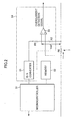
- Fig. 2 depicts a detail of the overcurrent detection circuit 54.
- the overcurrent detection circuit 54 is composed of a D/A converter 55, resistances R1 and R2, and a comparator 56. It is noted that the microcontroller 51, the memory 52, and a resistance R0 that constitutes the current sensor 7, shown in Fig. 2, are identical with those shown in Fig. 1, respectively.
- the microcontroller 51 integrates the overcurrent detection values of the respective motor drive amplifiers 3a and 3b as stated above, and outputs the integrated value to the D/A converter 55.
- the D/A converter 55 converts this integrated overcurrent detection value into an analog voltage, and applies the voltage to a serial circuit of the resistances R1 and R2.
- the analog voltage corresponding to the integrated overcurrent detection value is divided by the resistances R1 and R2, and a resultant divided voltage is inputted to the comparator 56 as an overcurrent detection reference value Vref.
- the current flowing in the motor drive power supply 6 flows in the resistance R0 (current sensor 7) , and a voltage drop caused by the resistance R0 is inputted to the other terminal of the comparator 56. If the voltage drop caused by the resistance R0 exceeds the overcurrent detection reference value Vref, a high-level overcurrent detection signal is outputted from the comparator 56.
- the motor drive controller 1 transmits a drive command to the respective motor drive amplifiers 3a and 3b.
- the control circuits 31a and 31b in the motor drive amplifiers 3a and 3b control on-off of the switching elements of the inverter circuits 33a and 33b, respectively.
- the power supplied from the motor drive power supply 6 is supplied to the motors 4a and 4b via the inverter circuits 33a and 33b, thereby driving the motors 4a and 4b, respectively.
- the sum of current is detected by the current sensor 7 as stated above. Accordingly, if an overcurrent flows in one of the motor drive amplifiers 3a and 3b, then the current flowing in the resistance R0 of the current sensor 7 also increases, the voltage drop of the resistance R0 exceeds the overcurrent detection reference value Vref, and the overcurrent detection signal is outputted from the comparator 56.
- This overcurrent detection reference value Vref is set based on the integrated value of the overcurrent detection values that are the maximum currents allowed by the respective motor drive amplifiers connected to the motor drive power supply (in the example of Fig. 1, Vref is set based on the sum of the overcurrent detection value of the motor drive amplifier 3a and that of the motor drive amplifier 3b). Therefore, if the number of the motor drive amplifiers connected to the motor drive power supply 6 changes, or if the motor drive amplifier under different specifications is used and the overcurrent detection value of the amplifier thereby changes, then the integrated overcurrent detection value to be set to the overcurrent detection circuit 54 can be changed, with the result that the overcurrent detection reference value Vref can be changed accordingly. It is thus possible to accurately detect the overcurrent.
- the overcurrent detection value corresponding to the overcurrent detected by the overcurrent detection means is set according to the number of the connected motor drive amplifiers and the specifications of the respective amplifiers. Therefore, the overcurrent can be appropriately detected.
Landscapes
- Engineering & Computer Science (AREA)
- Power Engineering (AREA)
- Control Of Multiple Motors (AREA)
- Protection Of Generators And Motors (AREA)
- Control Of Electric Motors In General (AREA)
Abstract
Description
Claims (2)
- Amotor drive system, comprising a motor drive power supply and a plurality of motor drive amplifiers connected to the motor drive power supply, and driving motors by the respective motor drive amplifiers, the motor drive system comprising:overcurrent detection means for detecting a current flowing in said motor drive power supply, whereinan overcurrent detection value to be detected as an overcurrent by said overcurrent detection means can be changed.
- The motor drive system according to claim 1, wherein
said motor drive amplifiers comprise memories that store specifications of the respective motor drive amplifiers,
said motor drive system further comprises:means for reading storage contents of said memories;overcurrent detection value storage means for storing overcurrent detection values corresponding to the specifications of the respective motor drive amplifiers; andmeans for reading the overcurrent detection values from the overcurrent detection value storage means based on the specifications read from said respective memories, and for integrating the overcurrent detection values, and wherein an integrated value of the overcurrent detection values of the plurality of motor drive amplifiers connected to said motor drive power supply is set as a reference value for detection made by said overcurrent detection means.
Applications Claiming Priority (2)
| Application Number | Priority Date | Filing Date | Title |
|---|---|---|---|
| JP2003149365A JP3851617B2 (en) | 2003-05-27 | 2003-05-27 | Motor drive device |
| JP2003149365 | 2003-05-27 |
Publications (2)
| Publication Number | Publication Date |
|---|---|
| EP1482634A2 true EP1482634A2 (en) | 2004-12-01 |
| EP1482634A3 EP1482634A3 (en) | 2009-02-11 |
Family
ID=33128220
Family Applications (1)
| Application Number | Title | Priority Date | Filing Date |
|---|---|---|---|
| EP04253086A Withdrawn EP1482634A3 (en) | 2003-05-27 | 2004-05-26 | Motor drive system |
Country Status (4)
| Country | Link |
|---|---|
| US (1) | US7126300B2 (en) |
| EP (1) | EP1482634A3 (en) |
| JP (1) | JP3851617B2 (en) |
| CN (1) | CN1320745C (en) |
Cited By (3)
| Publication number | Priority date | Publication date | Assignee | Title |
|---|---|---|---|---|
| CN102201766A (en) * | 2010-03-22 | 2011-09-28 | 东元电机股份有限公司 | Motor driver |
| EP2079159A3 (en) * | 2008-01-09 | 2015-06-24 | Fanuc Corporation | Motor drive apparatus equipped with dynamic braking circuit fault detection capability |
| EP2592736A3 (en) * | 2011-11-14 | 2015-07-29 | Rockwell Automation Technologies, Inc. | System and method for managing DC link switching harmonics |
Families Citing this family (11)
| Publication number | Priority date | Publication date | Assignee | Title |
|---|---|---|---|---|
| JP2005224075A (en) * | 2004-02-09 | 2005-08-18 | Sanyo Electric Co Ltd | Inverter device |
| JP4692043B2 (en) * | 2005-03-30 | 2011-06-01 | 株式会社デンソー | Electronic control unit for electric motor |
| DE102006049507B4 (en) * | 2006-10-17 | 2016-05-25 | Sew-Eurodrive Gmbh & Co Kg | Plant and method for operating a plant |
| JP2008104266A (en) * | 2006-10-18 | 2008-05-01 | Matsushita Electric Ind Co Ltd | Motor drive device and motor drive device for washing and drying machine |
| JP5217380B2 (en) * | 2007-11-16 | 2013-06-19 | ダイキン工業株式会社 | Correction constant calculation system and correction constant calculation method |
| JP5297641B2 (en) * | 2007-11-29 | 2013-09-25 | セミコンダクター・コンポーネンツ・インダストリーズ・リミテッド・ライアビリティ・カンパニー | Motor drive circuit |
| JP2010088187A (en) * | 2008-09-30 | 2010-04-15 | Sanyo Electric Co Ltd | Motor control circuit |
| CN101728817A (en) | 2008-10-17 | 2010-06-09 | 鸿富锦精密工业(深圳)有限公司 | Multi-axis driving system |
| JP5846818B2 (en) * | 2011-09-16 | 2016-01-20 | ミネベア株式会社 | Power control device |
| JP6829094B2 (en) * | 2017-02-02 | 2021-02-10 | 株式会社東芝 | Power system |
| US11689124B2 (en) | 2021-01-12 | 2023-06-27 | Snap-On Incorporated | Controlling brushless motor commutation |
Family Cites Families (64)
| Publication number | Priority date | Publication date | Assignee | Title |
|---|---|---|---|---|
| US3371248A (en) * | 1962-08-13 | 1968-02-27 | Westinghouse Electric Corp | Overcurrent protection apparatus |
| US3809335A (en) * | 1972-06-29 | 1974-05-07 | Ibm | Web movement control in a reel-to-reel web transport |
| CA1042110A (en) * | 1974-01-17 | 1978-11-07 | Odo J. Struger | Malfunction detection system for a programmable controller |
| US3984065A (en) * | 1975-03-13 | 1976-10-05 | Computer Peripherals, Inc. | Tape transport system |
| ES468764A1 (en) * | 1978-04-13 | 1979-10-01 | Arteche Instr Sistemas | A new delayed action electrical protection device, depending on an adjusted magnitude. |
| IT1193453B (en) * | 1979-09-03 | 1988-06-22 | Puntimatic Snc D Musiani Franc | OVERCURRENT AND LACK OF PHASE DETECTOR DEVICE |
| US4435706A (en) * | 1981-11-02 | 1984-03-06 | Allen-Bradley Company | Switch network |
| US4481553A (en) * | 1982-04-05 | 1984-11-06 | General Electric Company | Protection circuit |
| US4456865A (en) * | 1982-04-22 | 1984-06-26 | The Babcock & Wilcox Company | High torque servo positioner using 3 phase variable frequency constant torque controller |
| JPS59148586A (en) * | 1982-09-30 | 1984-08-25 | Aisin Seiki Co Ltd | Drive controller for vehicle motor drive device |
| US4509088A (en) * | 1982-09-30 | 1985-04-02 | Square D Company | Motor protector relay with memory of overload |
| JPS60144284A (en) * | 1984-01-05 | 1985-07-30 | 三菱電機株式会社 | Controller for alternating current elevator |
| US4628397A (en) * | 1984-06-04 | 1986-12-09 | General Electric Co. | Protected input/output circuitry for a programmable controller |
| US4672501A (en) * | 1984-06-29 | 1987-06-09 | General Electric Company | Circuit breaker and protective relay unit |
| US4631625A (en) * | 1984-09-27 | 1986-12-23 | Siemens Energy & Automation, Inc. | Microprocessor controlled circuit breaker trip unit |
| EP0213482B1 (en) * | 1985-08-13 | 1991-01-02 | Aisin Seiki Kabushiki Kaisha | Apparatus for controlling the attitude of vehicle mounted device |
| JPH0695807B2 (en) * | 1986-04-15 | 1994-11-24 | 株式会社山本製作所 | Overcurrent prevention method in grain dryer |
| JPS63204307A (en) * | 1987-02-19 | 1988-08-24 | Fanuc Ltd | Overcurrent detector |
| US5123080A (en) * | 1987-03-20 | 1992-06-16 | Ranco Incorporated Of Delaware | Compressor drive system |
| US4893479A (en) * | 1987-03-20 | 1990-01-16 | Ranco Electronics Division | Compressor drive system |
| US4812943A (en) * | 1987-12-24 | 1989-03-14 | Sundstrand Corp. | Current fault protection system |
| US4920476A (en) * | 1988-05-27 | 1990-04-24 | Westinghouse Electric Corp. | Electronic control for lighting panelboards |
| US4967304A (en) * | 1988-10-11 | 1990-10-30 | General Electric Company | Digital circuit interrupter with electric motor trip parameters |
| FR2646738B1 (en) * | 1989-05-03 | 1991-07-05 | Merlin Gerin | STATIC TRIGGER FOR A THREE-PHASE NETWORK PROTECTION CIRCUIT BREAKER FOR DETECTING THE TYPE OF FAULT |
| US5038246A (en) * | 1989-08-31 | 1991-08-06 | Square D Company | Fault powered, processor controlled circuit breaker trip system having reliable tripping operation |
| CA1330234C (en) * | 1989-09-29 | 1994-06-14 | Timothy M. Wilkerson | Overcurrent protection relay with communications |
| JPH03270631A (en) * | 1990-03-16 | 1991-12-02 | Mitsubishi Electric Corp | 4-pole circuit breaker |
| US5151866A (en) * | 1990-03-30 | 1992-09-29 | The Dow Chemical Company | High speed power analyzer |
| US5525985A (en) * | 1990-12-28 | 1996-06-11 | Eaton Corporation | Sure chip |
| US5627716A (en) * | 1990-12-28 | 1997-05-06 | Eaton Corporation | Overcurrent protection device |
| US6055145A (en) * | 1990-12-28 | 2000-04-25 | Eaton Corporation | Overcurrent protection device with visual indicators for trip and programming functions |
| US5270898A (en) * | 1990-12-28 | 1993-12-14 | Westinghouse Electric Corp. | Sure chip plus |
| JP2626326B2 (en) * | 1991-07-31 | 1997-07-02 | 三菱電機株式会社 | Motor control unit |
| JP2725500B2 (en) * | 1991-10-23 | 1998-03-11 | 三菱電機株式会社 | Inverter air conditioner |
| CN1029361C (en) * | 1991-11-16 | 1995-07-19 | 肖金炳 | Overcurrent protector for motor |
| JPH06141550A (en) * | 1992-10-19 | 1994-05-20 | S G:Kk | Inverter and motor control system |
| DE4241849C2 (en) * | 1992-12-11 | 1996-04-25 | Danfoss As | Steering system for vehicles or ships |
| US5357178A (en) * | 1993-07-09 | 1994-10-18 | Gettys Corporation | Web tensioning control system |
| US5375052A (en) * | 1993-08-11 | 1994-12-20 | Dimensions Unlimited, Inc. | Co-inverter apparatus |
| CN2165560Y (en) * | 1993-09-29 | 1994-05-18 | 李佩平 | Universal motor protector |
| US5633774A (en) * | 1994-02-25 | 1997-05-27 | Siemens Energy & Automation Inc | Electronic overload relay power source |
| JPH07241096A (en) * | 1994-02-28 | 1995-09-12 | Unisia Jecs Corp | Electric motor controller |
| US5600233A (en) * | 1995-08-22 | 1997-02-04 | Chicago Stage Equipment Co. | Electronic power control circuit |
| US5767744A (en) * | 1995-11-22 | 1998-06-16 | Qsc Audio Products, Inc. | Lightweight fixed frequency discontinuous resonant power supply for audio amplifiers |
| FR2756118B1 (en) * | 1996-11-20 | 1999-02-05 | Moteurs Fox | ELECTRIC MOTOR MACHINE WITH INERTIAL STORAGE POWERED BY AN AUTONOMOUS CONTINUOUS VOLTAGE SOURCE |
| JP3807022B2 (en) * | 1997-05-09 | 2006-08-09 | 株式会社デンソー | Motor control device and motor control method |
| JPH10337084A (en) * | 1997-05-30 | 1998-12-18 | Aisin Seiki Co Ltd | Overheating protection device for switching module |
| US5856903A (en) * | 1997-11-12 | 1999-01-05 | General Electric Company | Matching overcurrent characteristic curves |
| JP3518670B2 (en) * | 1998-09-14 | 2004-04-12 | パイオニア株式会社 | Feeding speed control device of information reading point in disc player |
| US6198613B1 (en) * | 1998-12-23 | 2001-03-06 | Hamilton Sundstrand Corporation | Method and apparatus for distributing alternating electrical current to motors via a direct current bus |
| JP2000287493A (en) * | 1999-03-30 | 2000-10-13 | Matsushita Electric Ind Co Ltd | Motor protection device |
| US6198241B1 (en) * | 1999-07-07 | 2001-03-06 | Westinghouse Air Brake Company | Motor protection for a powered door system |
| JP2001028893A (en) * | 1999-07-12 | 2001-01-30 | Fanuc Ltd | Motor controller |
| JP2001086785A (en) * | 1999-09-16 | 2001-03-30 | Fujitsu General Ltd | Motor control method and device |
| US6754026B1 (en) * | 1999-10-28 | 2004-06-22 | International Business Machines Corporation | Tape transport servo system and method for a computer tape drive |
| JP3368563B2 (en) * | 2000-01-11 | 2003-01-20 | 伊東電機株式会社 | Conveyor equipment |
| JP2001268781A (en) * | 2000-03-16 | 2001-09-28 | Copyer Co Ltd | Motor overcurrent detecting method and recording device |
| US6767308B2 (en) * | 2001-03-09 | 2004-07-27 | Shimano Inc. | Method of controlling bicycle assembly |
| US6710574B2 (en) * | 2001-09-21 | 2004-03-23 | Eaton Corporation | Reversible DC motor drive including a DC/DC converter and four quadrant DC/DC controller |
| JP2003111263A (en) * | 2001-09-27 | 2003-04-11 | Sanyo Electric Co Ltd | Protection circuit |
| JP3608553B2 (en) * | 2002-01-23 | 2005-01-12 | トヨタ自動車株式会社 | Inverter for AC generator motor |
| AU2003217663A1 (en) * | 2002-02-25 | 2003-09-09 | General Electric Company | Method and system for conditionally triggered system data capture |
| US7136269B2 (en) * | 2002-04-24 | 2006-11-14 | Sanyo Electric Co., Ltd. | Inverted circuit overcurrent protection device and hybrid integrated circuit device with the same incorporated |
| JP2004040922A (en) * | 2002-07-04 | 2004-02-05 | Sanyo Electric Co Ltd | Inverter circuit device with temperature detection circuit |
-
2003
- 2003-05-27 JP JP2003149365A patent/JP3851617B2/en not_active Expired - Fee Related
-
2004
- 2004-05-24 US US10/851,087 patent/US7126300B2/en not_active Expired - Fee Related
- 2004-05-24 CN CNB2004100383683A patent/CN1320745C/en not_active Expired - Fee Related
- 2004-05-26 EP EP04253086A patent/EP1482634A3/en not_active Withdrawn
Cited By (4)
| Publication number | Priority date | Publication date | Assignee | Title |
|---|---|---|---|---|
| EP2079159A3 (en) * | 2008-01-09 | 2015-06-24 | Fanuc Corporation | Motor drive apparatus equipped with dynamic braking circuit fault detection capability |
| CN102201766A (en) * | 2010-03-22 | 2011-09-28 | 东元电机股份有限公司 | Motor driver |
| EP2592736A3 (en) * | 2011-11-14 | 2015-07-29 | Rockwell Automation Technologies, Inc. | System and method for managing DC link switching harmonics |
| US9270210B2 (en) | 2011-11-14 | 2016-02-23 | Rockwell Automation Technologies, Inc. | System and method for managing DC link switching harmonics |
Also Published As
| Publication number | Publication date |
|---|---|
| CN1574602A (en) | 2005-02-02 |
| US20040239271A1 (en) | 2004-12-02 |
| EP1482634A3 (en) | 2009-02-11 |
| JP2004357362A (en) | 2004-12-16 |
| JP3851617B2 (en) | 2006-11-29 |
| US7126300B2 (en) | 2006-10-24 |
| CN1320745C (en) | 2007-06-06 |
Similar Documents
| Publication | Publication Date | Title |
|---|---|---|
| US7126300B2 (en) | Motor drive system | |
| US7495402B2 (en) | Fan motor controller | |
| JP2001028893A (en) | Motor controller | |
| CN111164848B (en) | Systems and methods for providing bidirectional transient voltage support and power | |
| US8063589B2 (en) | Drive system for multiple motors | |
| US5654630A (en) | Contactless sensor driven by single power supply | |
| US4547715A (en) | Current control circuit | |
| US5153809A (en) | Self diagnosing circuit for a load control circuit | |
| US8030869B2 (en) | Drive amplifier system and over-current detection method for the same | |
| US5159542A (en) | Selectable hysteresis controller for pulse width modulated inverter | |
| JP2000346893A (en) | Power module | |
| JPS62262621A (en) | Potential indicator for generator | |
| TWI407110B (en) | Multi-axises drive system | |
| JP3180298B2 (en) | Motor protection circuit | |
| CN204631518U (en) | A kind of sensor-based system power supply collator of position-based information | |
| JP3148811B2 (en) | DC brushless motor current limiting circuit | |
| JPH01303054A (en) | power supply | |
| JPH0332392A (en) | Motor driver | |
| JP2003530803A (en) | Power supply control apparatus and method | |
| JPH04368875A (en) | Abnormality detection device | |
| JP2861179B2 (en) | Motor control drive | |
| CN104991485A (en) | Sensing system power supply ordering device and method based on position information | |
| JP2015116043A (en) | DC / DC converter | |
| JPH02294295A (en) | Motor driving device | |
| JP2000175486A (en) | Disconnection detecting device for lead wire of motor |
Legal Events
| Date | Code | Title | Description |
|---|---|---|---|
| PUAI | Public reference made under article 153(3) epc to a published international application that has entered the european phase |
Free format text: ORIGINAL CODE: 0009012 |
|
| AK | Designated contracting states |
Kind code of ref document: A2 Designated state(s): AT BE BG CH CY CZ DE DK EE ES FI FR GB GR HU IE IT LI LU MC NL PL PT RO SE SI SK TR |
|
| AX | Request for extension of the european patent |
Extension state: AL HR LT LV MK |
|
| PUAL | Search report despatched |
Free format text: ORIGINAL CODE: 0009013 |
|
| AK | Designated contracting states |
Kind code of ref document: A3 Designated state(s): AT BE BG CH CY CZ DE DK EE ES FI FR GB GR HU IE IT LI LU MC NL PL PT RO SE SI SK TR |
|
| AX | Request for extension of the european patent |
Extension state: AL HR LT LV MK |
|
| RIC1 | Information provided on ipc code assigned before grant |
Ipc: H02H 7/08 20060101AFI20090107BHEP |
|
| AKX | Designation fees paid | ||
| REG | Reference to a national code |
Ref country code: DE Ref legal event code: 8566 |
|
| STAA | Information on the status of an ep patent application or granted ep patent |
Free format text: STATUS: THE APPLICATION IS DEEMED TO BE WITHDRAWN |
|
| 18D | Application deemed to be withdrawn |
Effective date: 20090812 |