EP1482522A2 - Magnetic core device and assembly method - Google Patents
Magnetic core device and assembly method Download PDFInfo
- Publication number
- EP1482522A2 EP1482522A2 EP04076357A EP04076357A EP1482522A2 EP 1482522 A2 EP1482522 A2 EP 1482522A2 EP 04076357 A EP04076357 A EP 04076357A EP 04076357 A EP04076357 A EP 04076357A EP 1482522 A2 EP1482522 A2 EP 1482522A2
- Authority
- EP
- European Patent Office
- Prior art keywords
- core member
- magnetic core
- magnetic
- width
- length
- Prior art date
- Legal status (The legal status is an assumption and is not a legal conclusion. Google has not performed a legal analysis and makes no representation as to the accuracy of the status listed.)
- Granted
Links
- 230000005291 magnetic effect Effects 0.000 title claims abstract description 119
- 238000000034 method Methods 0.000 title description 4
- 230000004907 flux Effects 0.000 claims description 47
- 239000004020 conductor Substances 0.000 claims 2
- 239000011162 core material Substances 0.000 description 150
- 239000000853 adhesive Substances 0.000 description 6
- 230000001070 adhesive effect Effects 0.000 description 6
- 230000000712 assembly Effects 0.000 description 3
- 238000000429 assembly Methods 0.000 description 3
- 230000009467 reduction Effects 0.000 description 3
- 239000003302 ferromagnetic material Substances 0.000 description 1
- 230000002401 inhibitory effect Effects 0.000 description 1
- 238000009434 installation Methods 0.000 description 1
- 239000000696 magnetic material Substances 0.000 description 1
- 238000004519 manufacturing process Methods 0.000 description 1
- 230000013011 mating Effects 0.000 description 1
- 238000012986 modification Methods 0.000 description 1
- 230000004048 modification Effects 0.000 description 1
- 238000000926 separation method Methods 0.000 description 1
Images

Classifications
-
- H—ELECTRICITY
- H01—ELECTRIC ELEMENTS
- H01F—MAGNETS; INDUCTANCES; TRANSFORMERS; SELECTION OF MATERIALS FOR THEIR MAGNETIC PROPERTIES
- H01F27/00—Details of transformers or inductances, in general
- H01F27/24—Magnetic cores
- H01F27/26—Fastening parts of the core together; Fastening or mounting the core on casing or support
-
- H—ELECTRICITY
- H01—ELECTRIC ELEMENTS
- H01F—MAGNETS; INDUCTANCES; TRANSFORMERS; SELECTION OF MATERIALS FOR THEIR MAGNETIC PROPERTIES
- H01F27/00—Details of transformers or inductances, in general
- H01F27/28—Coils; Windings; Conductive connections
- H01F27/2804—Printed windings
Definitions
- the present invention generally relates to magnetic devices, and more particularly relates to the assembly of magnetic cores for forming a magnetic device.
- Some electronic devices such as inductors and transformers employ magnetic cores that generate an induced magnetic flux.
- Many conventional magnetic cores are assembled together as two separate magnetic core members that form a magnetic flux circuit.
- One approach employs a pair of generally E-shaped magnetic core members that are assembled such that the open ends of each arm join with each other to provide the induced magnetic flux path.
- Each arm has a connecting surface designed to align with like size and shape surface areas on the opposing magnetic core member.
- Another approach employs the assembly of a generally E-shaped magnetic core member assembled to a planar-shaped plate core member.
- the two magnetic core members both have the same general overall width and length.
- the two magnetic core members must be properly aligned to minimize magnetic flux losses.
- the alignment procedure is difficult to implement in some applications, such as in the assembly of core members for use as a transformer or inductor that is integrated into a printed circuit board.
- the installation of an upper core member onto a lower core member through the circuit board may occur in a blind operation, thus inhibiting assurance of precise alignment of the two core members.
- Misalignment of the two magnetic core members reduces the effective cross-sectional area of the conventional core device.
- the magnetic flux passing from one core member to the other misaligned core member is forced to crowd to the remaining contact surface to complete the magnetic flux path, which is known as flux crowding.
- Increased flux density or crowding may lead to core saturation near the adjoining surfaces which may produce unwanted thermal energy (heat).
- not all of the densified magnetic flux will make it through the reduced size of the adjoining surfaces, thereby causing some magnetic flux to pass outside of the core, which is known as flux fringing.
- flux fringing magnetic flux passes into the surrounding environment and possibly into the nearby circuitry where eddy currents are generated, energy is wasted, and noise may be introduced.
- Flux fringing and flux crowding may occur in conventional magnetic core assemblies where the two magnetic core members are shifted relative to each other and/or are rotated in a skewed alignment. In either situation, a reduction in the cross-sectional area of the magnetic flux circuit is realized which reduces overall inductance. Additionally, a reduction in the cross-sectional area increases the flux density or crowding in the device and also results in flux fringing. The resultant reduction in cross-sectional area of the magnetic flux circuit due to shifted and/or skewed alignment of the two core members therefore results in reduced performance.
- a magnetic core device made up of the assembly of two magnetic core members that does not suffer from a reduced magnetic flux path area due to the alignment procedure. It is further desirable to provide for a magnetic core device having two core members that may be easily aligned to minimize flux fringing and flux crowding so as to optimize performance of the magnetic core device. It is particularly desirable to provide for such a magnetic core device that may be assembled onto a circuit board, such as a printed circuit board, where shifting and/or skewed alignment of the core members may occur.
- a magnetic core device having first and second magnetic core members.
- the first core member has a generally open shape and first and second surfaces.
- the first and second surfaces have first and second surface areas, respectively.
- the second magnetic core member has third and fourth surfaces for joining with the first and second surfaces, respectively, of the first magnetic core member.
- the third and fourth surfaces have oversized third and fourth surface areas such that the third surface area is greater than the first surface area, and the fourth surface area is greater than the second surface area.
- the magnetic core device includes a generally E-shaped magnetic core member and a generally planar magnetic core member.
- the generally E-shaped magnetic core member has first, second, and third end surfaces for providing magnetic flux.
- the first magnetic core member has a length and a width.
- the first, second, and third end surfaces of the E-shaped core member are assembled to join the generally planar magnetic core member to form a magnetic flux circuit.
- the generally planar magnetic core member has a length and a width that is greater than at least one of the length and width of the generally E-shaped core member.
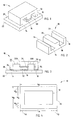
- a magnetic core device 10 is illustrated made up of the assembly of a first core member 12, shown as the upper member, and a second core member 22, shown as the lower core member.
- the first and second core members are made of magnetic material such as a ferromagnetic material for generating magnetic flux. In doing so, the first and second magnetic core members 12 and 22 are positioned in relation to each other to form substantially closed magnetic flux circuits as described herein.
- the magnetic core device 10 may be used in any of a number of applications including use in an inductor, a transformer, or other components that require magnetic flux.
- the second magnetic core member 22 is shown as a substantially planar-shaped plate having an upper surface 30 engaging or in close proximity to end surface areas of the first magnetic core member 12 to form magnetic flux paths.
- the first magnetic core member 12 is shown configured as an E-shaped member having first, second, and third arms 14, 16, and 18.
- the first and third arms 14 and 18 are formed at opposite ends of core member 12.
- the second arm 16 is formed midway between the first and second arms 14 and 18.
- the second arm 16 has a width of about twice the width of either of arms 14 and 18.
- the electrically conductive coil 50 may include a single turn coil, according to one embodiment. According to another embodiment, the electrically conductive coil 50 may be wound in a plurality of turns. The electrically conductive coil 50 allows current flow in a direction substantially perpendicular to the magnetic flux passing through the middle arm 16.
- the upper magnetic core member 12 is further shown in Fig. 2 having end surface areas 24, 26, and 28 for joining upper surface 30 of second core member 22 to complete the magnetic flux paths.
- the first end surface 24 is provided at the end of arm 14 and provides a surface area defined by its width and length.
- the second end surface 26 is formed at the end of second arm 16 and provides a surface area defined by its length and width.
- the third surface area 28 likewise is formed at the end of third arm 18 and is also defined by its length and width. The length extending from and including the first to the third surface areas 24 and 28 and the width of the surface areas 24, 26, and 28 defines the outer perimeter of the first magnetic core member 12.
- the magnetic core device 10 is further illustrated from a front view in Fig. 3 with the upper core member 12 substantially centered on lower core member 22.
- the upper core member 12 is shown adhered to the upper surface 30 of lower core member 22 via an adhesive 34.
- the adhesive 34 is disposed between end surfaces 24, 26, and 28 of upper core member 12 and upper surface 30 of lower core member 22.
- the adhesive 34 may include any of a number of known adhesives. The thickness of adhesive 34 will determine the separation distance, if any, between the adjoining upper and lower core members 12 and 22. However, it should be appreciated that the upper and lower core members 12 and 22 may be in direct contact with each other.
- any of a number of other techniques may be employed to retain the positioning of the first and second magnetic core members 12 and 22 fixed in place relative to each other.
- the first and second magnetic core members 12 and 22 may be fastened directly together or may be directly fastened to another supporting member such as a circuit board.
- an E-shaped upper core member 12 provides first and second magnetic flux circuits that allow for the generation of first and second magnetic flux paths 32A and 32B which are shown in dashed lines in Fig. 3.
- the magnetic flux paths 32A and 32B indicate magnetic flux circulates through end arms 14 and 18, and magnetic flux paths 32A and 32B are joined together in the same direction through the middle arm 16.
- the magnetic flux through middle arm 16 travels substantially perpendicular to current flow in the electrically conductive coil 50.
- the magnetic core device 10 is provided with an over-sized lower core member 22 as compared to the size of the upper core member 12.
- the upper core member 12 has an overall length L A and an overall width W A which generally defines the perimeter of the upper core member 12 including the perimeter of the magnetic flux path.
- the lower core member 22 has an overall length L B and an overall width W B , both of which are greater than the length L A and width W B of the upper core member 12.
- the lower core member has a length L B greater than length L A by an amount equal to 2L O .
- the lower core member 22 has a width W B greater than width W A by an amount equal to 2W O .
- the lower core member 22 has an oversize length L B and width W B greater than the length L A and width W A of the upper core member 12 by offset amounts equal to 2L O and 2W O , respectively.
- the oversized dimensions of the lower core member 22 relative to the upper core member 12 are sufficiently large enough to allow for shifted and/or skewed alignment of the two core members 12 and 22 relative to each other.
- the amount of oversize of lower core member 22 relative to upper core member 12 is preferably greater than a minimal amount of the maximum offset placement error tolerance of upper core member 12 plus the maximum dimensional tolerance allowed for the manufacture of the upper core member 12.
- the first and second core members 12 and 22 may be assembled together with a shifted alignment and/or a skewed alignment while substantially reducing or eliminating changes in inductance and reducing flux crowding and flux fringing. That is, the end surface areas 24, 26, and 28 of upper core member 12 remain in contact or near contact with upper surface 30 of lower core member 22, despite shifted and/or skewed alignment of the two core members 12 and 22, within a limited degree of relative movement. Despite some shifting and/or skew alignment, the oversized lower plate 22 allows the magnetic flux to circulate from one core member into the other core member and return back with little or no losses generally associated with reduced cross-sectional area at the adjoining surfaces.
- the magnetic core device 10 is illustrated in Fig. 5 with the upper core member 12 shifted along its length relative to the lower core member 22.
- the two core members 12 and 22 are able to shift relative to each other while still providing contact or near contact between the two core members 12 and 22 to complete the magnetic flux circuit.
- the upper core member 12 is shown skewed relative to the lower core member 22.
- the upper core member 12 is able to be skewed in its alignment relative to the lower core member 22 to within a limited degree of movement.
- the printed circuit board 40 includes first, second, and third rectangular cutout openings 44, 46, and 48.
- Each of the cutout openings 44-48 has a dimension greater than the outer dimensions of arms 14, 16, and 18, respectively.
- the openings 44, 46, and 48 are generally oversized relative to the outer perimeter dimensions of arms 14, 16, and 18, respectively, to enable ease of the blind assembly of the components, which further results in the possible shifted alignment and/or skewed alignment of upper core member 12 relative to lower core member 22.
- the upper core member 12 is inserted such that arms 14, 16, and 18 extend into cutout openings 44, 46, and 48, respectively, in printed circuit board 40.
- the lower core member plate 22 is then adhered or otherwise fastened to remain in position relative to the end surfaces 24, 26, and 28 of upper core member 12.
- the oversized core member plate 22 should be fabricated with an overall length L B and width W B sufficiently large enough to retain the mating end surfaces of upper core member 12 within the area dimensions of its upper surface area 30. However, in order to minimize cost, the oversized core member plate 22 should not be excessively large. Thus, the oversized core member 22 need only be large enough to accommodate the maximum tolerance of possible shifting and/or skew alignment of the upper and lower core members 12 and 22.
- the magnetic core device 10 may be formed of other two-piece magnetic core assemblies that form a magnetic flux circuit.
- a single C-shaped or U-shaped core member may be assembled on an oversized plate-shaped core member according to another embodiment.
- Other examples of open face core members may include various other shaped cores including cores commonly referred to as RM cores, ER cores, PQ cores, and PT cores.
- a pair of open core members such as two E-shaped core members, may be assembled together, with one of the two E-shaped core members having enlarged (oversized) end surfaces formed in each of the arms to allow for shifted and/or skewed alignment of the adjoining end surfaces.
- the present invention advantageously provides for a magnetic core device 10 that is allowed to be assembled in a shifted and/or skewed alignment, without suffering from drawbacks experienced in conventional two part core assembly arrangements. It should be noted that while an initial inductance value of the assembled component employing the oversized core member may be slightly higher than with a perfectly aligned same-sized core assembly due to increased volume of the core material, it should be appreciated that once the inductance value is established no substantive further changes occur due to positioning of the two core members 12 and 22.
Landscapes
- Engineering & Computer Science (AREA)
- Power Engineering (AREA)
- Coils Or Transformers For Communication (AREA)
- Magnetic Heads (AREA)
Abstract
Description
The
Claims (15)
- A magnetic core device (10) comprising:a first magnetic core member (12) having a generally open shape and first and second surfaces (24 and 28), said first and second surfaces (24 and 28) having first and second surface areas, respectively; anda second magnetic core member (22) having third and fourth surfaces (30) for joining with the first and second surfaces (24 and 28), respectively, of the first magnetic core member (12) to from a magnetic flux path (32A or 32B), wherein the third and fourth surfaces (30) have oversized third and fourth surface areas such that the third surface area is greater than the first surface area and the fourth surface area is greater than the second surface area.
- The device as defined in claim 1, wherein the first magnetic core member (12) further includes a middle surface (26) formed between the first and second surfaces (24 and 28), and the second magnetic core member (22) comprises a middle surface (30) having an oversized area greater than the area of the middle surface (26) of the first magnetic core member (12).
- The device as defined in claim 2, wherein the first magnetic core member (12) comprises a generally E-shaped core member, and a second magnetic core member (22) comprises the generally planar core member.
- The device as defined in claim 1, wherein the second magnetic core member (22) has length (LB) and width (WB) dimensions greater than length (LA) and width (WA) dimensions of the first magnetic core member (12).
- The device as defined in claim 1, wherein the device (10) is mounted on a circuit board (40).
- The device as defined in claim 1, wherein the device (10) is employed in an inductor.
- The device as defined claim 1, wherein the device (10) is employed in a transformer.
- The device as defined in claim 1, further comprising an electrical conductor (50) wound around a magnetic flux path (32A or 32B) of the device (10).
- The device as defined in claim 1, wherein the first magnetic core member (12) is adhered to the second magnetic core member (22).
- A magnetic core device (10) comprising:a generally E-shaped magnetic core member (12) having first, second, and third surfaces (24, 26, and 28) for providing magnetic flux, said first magnetic core member (12) having a length (LA) and width (WA) ; anda generally planar magnetic core member (22) for joining the first, second, and third surfaces (24, 26, and 28) of the E-shaped core member (12) to form a magnetic flux circuit, said generally planar magnetic core member (22) having a length (LB) and width (WB), wherein at least one of the length (LB) and width (WB) of the generally planar core member (22) is greater than at least one of the corresponding length (LA) and width (WA) of the generally E-shaped core member (12).
- The magnetic device as defined in claim 10, wherein the generally planar magnetic core member (22) has both the length (LB) and width (WB) greater than the corresponding length (LA) and width (WA) of the E-shaped magnetic core member (12).
- The magnetic device as defined in claim 10, wherein the E-shaped magnetic core member (12) has first and second arms (14 and 18) formed at opposite ends and a third arm (16) formed substantially midway between the first and second arms (14 and 18), wherein the first, second, and third arms (14, 16, and 18) contain the first, second, and third surfaces (24, 26, and 28).
- The device as defined in claim 1, further comprising an electrical conductor (50) wound around a magnetic flux path (32A or 32B) of the device (10).
- The device as defined in claim 1, wherein the first magnetic core member (12) is adhered to the second magnetic core member (22).
- The device as defined in claim 1, wherein the device (10) is mounted on a circuit board (40).
Applications Claiming Priority (2)
| Application Number | Priority Date | Filing Date | Title |
|---|---|---|---|
| US446061 | 2003-05-27 | ||
| US10/446,061 US6980078B2 (en) | 2003-05-27 | 2003-05-27 | Magnetic core device and assembly method |
Publications (3)
| Publication Number | Publication Date |
|---|---|
| EP1482522A2 true EP1482522A2 (en) | 2004-12-01 |
| EP1482522A3 EP1482522A3 (en) | 2005-04-13 |
| EP1482522B1 EP1482522B1 (en) | 2008-01-09 |
Family
ID=33131555
Family Applications (1)
| Application Number | Title | Priority Date | Filing Date |
|---|---|---|---|
| EP04076357A Expired - Lifetime EP1482522B1 (en) | 2003-05-27 | 2004-05-05 | Magnetic core device and assembly method |
Country Status (4)
| Country | Link |
|---|---|
| US (1) | US6980078B2 (en) |
| EP (1) | EP1482522B1 (en) |
| AT (1) | ATE383650T1 (en) |
| DE (1) | DE602004011143T2 (en) |
Families Citing this family (9)
| Publication number | Priority date | Publication date | Assignee | Title |
|---|---|---|---|---|
| TW201103044A (en) * | 2009-07-03 | 2011-01-16 | Magic Technology Co Ltd | Inductance component with gap and manufacturing method thereof |
| US8077006B2 (en) * | 2010-04-27 | 2011-12-13 | Harris Corporation | Transmission line impedance transformer and related methods |
| JP5319630B2 (en) * | 2010-09-03 | 2013-10-16 | 本田技研工業株式会社 | Combined transformer |
| US20140275915A1 (en) * | 2013-03-13 | 2014-09-18 | Medtronic, Inc. | Implantable medical device including a molded planar transformer |
| US10910150B2 (en) * | 2015-11-30 | 2021-02-02 | Intel Corporation | Reconfigurable coupled inductor |
| US10177641B2 (en) * | 2016-07-26 | 2019-01-08 | The Boeing Company | Stator assembly including stator elements with slotted stator cores for use in an electrical motor |
| JP6636089B2 (en) * | 2018-06-01 | 2020-01-29 | 株式会社タムラ製作所 | Electronic components |
| CN112185679A (en) * | 2020-10-22 | 2021-01-05 | 海宁市星火电子有限责任公司 | Pre-positioning device of low-coercivity E-type magnetic core |
| US20260121272A1 (en) * | 2024-10-31 | 2026-04-30 | Allegro Microsystems, Llc | Multi-channel isolation transformer and gate driver structures |
Family Cites Families (6)
| Publication number | Priority date | Publication date | Assignee | Title |
|---|---|---|---|---|
| US4864486A (en) * | 1988-07-29 | 1989-09-05 | International Business Machines Corporation | Plank and frame transformer |
| JP3074853B2 (en) | 1991-10-28 | 2000-08-07 | 松下電器産業株式会社 | Inductance component and its manufacturing method |
| NO944266L (en) | 1993-11-15 | 1995-05-16 | Hughes Aircraft Co | Inductive charging system |
| JP2000124032A (en) | 1998-03-06 | 2000-04-28 | Nippon Paint Co Ltd | Film, coil or transformer consisting of amorphous metal foil and insulating resin layer |
| US6456069B1 (en) * | 1999-03-05 | 2002-09-24 | The United States Of America As Represented By The Secretary Of The Navy | Fluxgate magnetic field sensor incorporating ferromagnetic test material into its magnetic circuitry |
| US6392519B1 (en) | 2000-11-03 | 2002-05-21 | Delphi Technologies, Inc. | Magnetic core mounting system |
-
2003
- 2003-05-27 US US10/446,061 patent/US6980078B2/en not_active Expired - Lifetime
-
2004
- 2004-05-05 EP EP04076357A patent/EP1482522B1/en not_active Expired - Lifetime
- 2004-05-05 DE DE602004011143T patent/DE602004011143T2/en not_active Expired - Lifetime
- 2004-05-05 AT AT04076357T patent/ATE383650T1/en not_active IP Right Cessation
Also Published As
| Publication number | Publication date |
|---|---|
| EP1482522B1 (en) | 2008-01-09 |
| DE602004011143T2 (en) | 2009-01-02 |
| ATE383650T1 (en) | 2008-01-15 |
| US20040239466A1 (en) | 2004-12-02 |
| EP1482522A3 (en) | 2005-04-13 |
| US6980078B2 (en) | 2005-12-27 |
| DE602004011143D1 (en) | 2008-02-21 |
Similar Documents
| Publication | Publication Date | Title |
|---|---|---|
| US6636140B2 (en) | High-frequency large current handling transformer | |
| KR0165948B1 (en) | Choke coil | |
| US6980077B1 (en) | Composite magnetic core for switch-mode power converters | |
| TWI275109B (en) | Improved inductive devices and methods | |
| US7605682B2 (en) | Magnetic core type laminated inductor | |
| US8258907B2 (en) | Highly coupled inductor | |
| US5929734A (en) | Coil former for a flat coil | |
| US7646281B2 (en) | Snap-together choke and transformer assembly for an electric arc welder | |
| US6980078B2 (en) | Magnetic core device and assembly method | |
| US12394554B2 (en) | Low profile high current coupled winding electromagnetic component | |
| JPH0794354A (en) | Non-contact connector | |
| US12417875B2 (en) | Electronic device | |
| JPH09162035A (en) | Coil device | |
| JP2008085004A (en) | Loosely-coupled transformer and switching power supply | |
| US20240161965A1 (en) | Transmitter with non-closed magnet core | |
| US12057257B2 (en) | Multi-layer coil structure and inductor | |
| JP2007324197A (en) | Inductor | |
| JPH08148353A (en) | Reactor | |
| KR102858803B1 (en) | Coil and magnetic component including the same | |
| JPH11186055A (en) | Composite magnetic components | |
| FI113810B (en) | Process for producing a magnetic power component and a magnetic power component | |
| JP4021746B2 (en) | Circuit board mounting structure for power supply coil components | |
| JP3218585B2 (en) | Print coil type transformer | |
| JPH11186073A (en) | Composite magnetic components | |
| KR102075955B1 (en) | Two-in-one planer inductor |
Legal Events
| Date | Code | Title | Description |
|---|---|---|---|
| PUAI | Public reference made under article 153(3) epc to a published international application that has entered the european phase |
Free format text: ORIGINAL CODE: 0009012 |
|
| AK | Designated contracting states |
Kind code of ref document: A2 Designated state(s): AT BE BG CH CY CZ DE DK EE ES FI FR GB GR HU IE IT LI LU MC NL PL PT RO SE SI SK TR |
|
| AX | Request for extension of the european patent |
Extension state: AL HR LT LV MK |
|
| PUAL | Search report despatched |
Free format text: ORIGINAL CODE: 0009013 |
|
| AK | Designated contracting states |
Kind code of ref document: A3 Designated state(s): AT BE BG CH CY CZ DE DK EE ES FI FR GB GR HU IE IT LI LU MC NL PL PT RO SE SI SK TR |
|
| AX | Request for extension of the european patent |
Extension state: AL HR LT LV MK |
|
| 17P | Request for examination filed |
Effective date: 20051013 |
|
| AKX | Designation fees paid |
Designated state(s): AT BE BG CH CY CZ DE DK EE ES FI FR GB GR HU IE IT LI LU MC NL PL PT RO SE SI SK TR |
|
| 17Q | First examination report despatched |
Effective date: 20061115 |
|
| GRAP | Despatch of communication of intention to grant a patent |
Free format text: ORIGINAL CODE: EPIDOSNIGR1 |
|
| GRAS | Grant fee paid |
Free format text: ORIGINAL CODE: EPIDOSNIGR3 |
|
| GRAA | (expected) grant |
Free format text: ORIGINAL CODE: 0009210 |
|
| AK | Designated contracting states |
Kind code of ref document: B1 Designated state(s): AT BE BG CH CY CZ DE DK EE ES FI FR GB GR HU IE IT LI LU MC NL PL PT RO SE SI SK TR |
|
| REG | Reference to a national code |
Ref country code: GB Ref legal event code: FG4D |
|
| REG | Reference to a national code |
Ref country code: CH Ref legal event code: EP |
|
| REG | Reference to a national code |
Ref country code: IE Ref legal event code: FG4D |
|
| REF | Corresponds to: |
Ref document number: 602004011143 Country of ref document: DE Date of ref document: 20080221 Kind code of ref document: P |
|
| PG25 | Lapsed in a contracting state [announced via postgrant information from national office to epo] |
Ref country code: NL Free format text: LAPSE BECAUSE OF FAILURE TO SUBMIT A TRANSLATION OF THE DESCRIPTION OR TO PAY THE FEE WITHIN THE PRESCRIBED TIME-LIMIT Effective date: 20080109 Ref country code: SI Free format text: LAPSE BECAUSE OF FAILURE TO SUBMIT A TRANSLATION OF THE DESCRIPTION OR TO PAY THE FEE WITHIN THE PRESCRIBED TIME-LIMIT Effective date: 20080109 |
|
| NLV1 | Nl: lapsed or annulled due to failure to fulfill the requirements of art. 29p and 29m of the patents act | ||
| PG25 | Lapsed in a contracting state [announced via postgrant information from national office to epo] |
Ref country code: ES Free format text: LAPSE BECAUSE OF FAILURE TO SUBMIT A TRANSLATION OF THE DESCRIPTION OR TO PAY THE FEE WITHIN THE PRESCRIBED TIME-LIMIT Effective date: 20080420 Ref country code: CH Free format text: LAPSE BECAUSE OF FAILURE TO SUBMIT A TRANSLATION OF THE DESCRIPTION OR TO PAY THE FEE WITHIN THE PRESCRIBED TIME-LIMIT Effective date: 20080109 Ref country code: LI Free format text: LAPSE BECAUSE OF FAILURE TO SUBMIT A TRANSLATION OF THE DESCRIPTION OR TO PAY THE FEE WITHIN THE PRESCRIBED TIME-LIMIT Effective date: 20080109 Ref country code: FI Free format text: LAPSE BECAUSE OF FAILURE TO SUBMIT A TRANSLATION OF THE DESCRIPTION OR TO PAY THE FEE WITHIN THE PRESCRIBED TIME-LIMIT Effective date: 20080109 |
|
| REG | Reference to a national code |
Ref country code: CH Ref legal event code: PL |
|
| PG25 | Lapsed in a contracting state [announced via postgrant information from national office to epo] |
Ref country code: AT Free format text: LAPSE BECAUSE OF FAILURE TO SUBMIT A TRANSLATION OF THE DESCRIPTION OR TO PAY THE FEE WITHIN THE PRESCRIBED TIME-LIMIT Effective date: 20080109 Ref country code: BG Free format text: LAPSE BECAUSE OF FAILURE TO SUBMIT A TRANSLATION OF THE DESCRIPTION OR TO PAY THE FEE WITHIN THE PRESCRIBED TIME-LIMIT Effective date: 20080409 |
|
| PG25 | Lapsed in a contracting state [announced via postgrant information from national office to epo] |
Ref country code: PT Free format text: LAPSE BECAUSE OF FAILURE TO SUBMIT A TRANSLATION OF THE DESCRIPTION OR TO PAY THE FEE WITHIN THE PRESCRIBED TIME-LIMIT Effective date: 20080609 Ref country code: BE Free format text: LAPSE BECAUSE OF FAILURE TO SUBMIT A TRANSLATION OF THE DESCRIPTION OR TO PAY THE FEE WITHIN THE PRESCRIBED TIME-LIMIT Effective date: 20080109 Ref country code: PL Free format text: LAPSE BECAUSE OF FAILURE TO SUBMIT A TRANSLATION OF THE DESCRIPTION OR TO PAY THE FEE WITHIN THE PRESCRIBED TIME-LIMIT Effective date: 20080109 |
|
| EN | Fr: translation not filed | ||
| PG25 | Lapsed in a contracting state [announced via postgrant information from national office to epo] |
Ref country code: SK Free format text: LAPSE BECAUSE OF FAILURE TO SUBMIT A TRANSLATION OF THE DESCRIPTION OR TO PAY THE FEE WITHIN THE PRESCRIBED TIME-LIMIT Effective date: 20080109 Ref country code: SE Free format text: LAPSE BECAUSE OF FAILURE TO SUBMIT A TRANSLATION OF THE DESCRIPTION OR TO PAY THE FEE WITHIN THE PRESCRIBED TIME-LIMIT Effective date: 20080409 Ref country code: CZ Free format text: LAPSE BECAUSE OF FAILURE TO SUBMIT A TRANSLATION OF THE DESCRIPTION OR TO PAY THE FEE WITHIN THE PRESCRIBED TIME-LIMIT Effective date: 20080109 Ref country code: DK Free format text: LAPSE BECAUSE OF FAILURE TO SUBMIT A TRANSLATION OF THE DESCRIPTION OR TO PAY THE FEE WITHIN THE PRESCRIBED TIME-LIMIT Effective date: 20080109 |
|
| PLBE | No opposition filed within time limit |
Free format text: ORIGINAL CODE: 0009261 |
|
| STAA | Information on the status of an ep patent application or granted ep patent |
Free format text: STATUS: NO OPPOSITION FILED WITHIN TIME LIMIT |
|
| PG25 | Lapsed in a contracting state [announced via postgrant information from national office to epo] |
Ref country code: RO Free format text: LAPSE BECAUSE OF FAILURE TO SUBMIT A TRANSLATION OF THE DESCRIPTION OR TO PAY THE FEE WITHIN THE PRESCRIBED TIME-LIMIT Effective date: 20080109 |
|
| 26N | No opposition filed |
Effective date: 20081010 |
|
| PG25 | Lapsed in a contracting state [announced via postgrant information from national office to epo] |
Ref country code: MC Free format text: LAPSE BECAUSE OF NON-PAYMENT OF DUE FEES Effective date: 20080531 |
|
| GBPC | Gb: european patent ceased through non-payment of renewal fee |
Effective date: 20080505 |
|
| PG25 | Lapsed in a contracting state [announced via postgrant information from national office to epo] |
Ref country code: EE Free format text: LAPSE BECAUSE OF FAILURE TO SUBMIT A TRANSLATION OF THE DESCRIPTION OR TO PAY THE FEE WITHIN THE PRESCRIBED TIME-LIMIT Effective date: 20080109 |
|
| PG25 | Lapsed in a contracting state [announced via postgrant information from national office to epo] |
Ref country code: FR Free format text: LAPSE BECAUSE OF FAILURE TO SUBMIT A TRANSLATION OF THE DESCRIPTION OR TO PAY THE FEE WITHIN THE PRESCRIBED TIME-LIMIT Effective date: 20081031 Ref country code: IE Free format text: LAPSE BECAUSE OF NON-PAYMENT OF DUE FEES Effective date: 20080505 |
|
| PG25 | Lapsed in a contracting state [announced via postgrant information from national office to epo] |
Ref country code: GB Free format text: LAPSE BECAUSE OF NON-PAYMENT OF DUE FEES Effective date: 20080505 |
|
| PG25 | Lapsed in a contracting state [announced via postgrant information from national office to epo] |
Ref country code: CY Free format text: LAPSE BECAUSE OF FAILURE TO SUBMIT A TRANSLATION OF THE DESCRIPTION OR TO PAY THE FEE WITHIN THE PRESCRIBED TIME-LIMIT Effective date: 20080109 |
|
| PG25 | Lapsed in a contracting state [announced via postgrant information from national office to epo] |
Ref country code: IT Free format text: LAPSE BECAUSE OF FAILURE TO SUBMIT A TRANSLATION OF THE DESCRIPTION OR TO PAY THE FEE WITHIN THE PRESCRIBED TIME-LIMIT Effective date: 20080109 |
|
| PG25 | Lapsed in a contracting state [announced via postgrant information from national office to epo] |
Ref country code: LU Free format text: LAPSE BECAUSE OF NON-PAYMENT OF DUE FEES Effective date: 20080505 Ref country code: HU Free format text: LAPSE BECAUSE OF FAILURE TO SUBMIT A TRANSLATION OF THE DESCRIPTION OR TO PAY THE FEE WITHIN THE PRESCRIBED TIME-LIMIT Effective date: 20080710 |
|
| PG25 | Lapsed in a contracting state [announced via postgrant information from national office to epo] |
Ref country code: TR Free format text: LAPSE BECAUSE OF FAILURE TO SUBMIT A TRANSLATION OF THE DESCRIPTION OR TO PAY THE FEE WITHIN THE PRESCRIBED TIME-LIMIT Effective date: 20080109 |
|
| PG25 | Lapsed in a contracting state [announced via postgrant information from national office to epo] |
Ref country code: GR Free format text: LAPSE BECAUSE OF FAILURE TO SUBMIT A TRANSLATION OF THE DESCRIPTION OR TO PAY THE FEE WITHIN THE PRESCRIBED TIME-LIMIT Effective date: 20080410 |
|
| REG | Reference to a national code |
Ref country code: DE Ref legal event code: R082 Ref document number: 602004011143 Country of ref document: DE Representative=s name: MANITZ FINSTERWALD PATENT- UND RECHTSANWALTSPA, DE Ref country code: DE Ref legal event code: R081 Ref document number: 602004011143 Country of ref document: DE Owner name: DELPHI TECHNOLOGIES IP LIMITED, BB Free format text: FORMER OWNER: DELPHI TECHNOLOGIES, INC., TROY, MICH., US |
|
| P01 | Opt-out of the competence of the unified patent court (upc) registered |
Effective date: 20230327 |
|
| PGFP | Annual fee paid to national office [announced via postgrant information from national office to epo] |
Ref country code: DE Payment date: 20230412 Year of fee payment: 20 |
|
| REG | Reference to a national code |
Ref country code: DE Ref legal event code: R071 Ref document number: 602004011143 Country of ref document: DE |