EP1482502A2 - Information reproducing apparatus and method - Google Patents
Information reproducing apparatus and method Download PDFInfo
- Publication number
- EP1482502A2 EP1482502A2 EP04252914A EP04252914A EP1482502A2 EP 1482502 A2 EP1482502 A2 EP 1482502A2 EP 04252914 A EP04252914 A EP 04252914A EP 04252914 A EP04252914 A EP 04252914A EP 1482502 A2 EP1482502 A2 EP 1482502A2
- Authority
- EP
- European Patent Office
- Prior art keywords
- data
- signal
- clock signal
- reproducing
- generating
- Prior art date
- Legal status (The legal status is an assumption and is not a legal conclusion. Google has not performed a legal analysis and makes no representation as to the accuracy of the status listed.)
- Granted
Links
Images


Classifications
-
- G—PHYSICS
- G11—INFORMATION STORAGE
- G11B—INFORMATION STORAGE BASED ON RELATIVE MOVEMENT BETWEEN RECORD CARRIER AND TRANSDUCER
- G11B20/00—Signal processing not specific to the method of recording or reproducing; Circuits therefor
- G11B20/10—Digital recording or reproducing
- G11B20/10009—Improvement or modification of read or write signals
- G11B20/10046—Improvement or modification of read or write signals filtering or equalising, e.g. setting the tap weights of an FIR filter
- G11B20/10212—Improvement or modification of read or write signals filtering or equalising, e.g. setting the tap weights of an FIR filter compensation for data shift, e.g. pulse-crowding effects
-
- G—PHYSICS
- G11—INFORMATION STORAGE
- G11B—INFORMATION STORAGE BASED ON RELATIVE MOVEMENT BETWEEN RECORD CARRIER AND TRANSDUCER
- G11B20/00—Signal processing not specific to the method of recording or reproducing; Circuits therefor
- G11B20/00086—Circuits for prevention of unauthorised reproduction or copying, e.g. piracy
- G11B20/00572—Circuits for prevention of unauthorised reproduction or copying, e.g. piracy involving measures which change the format of the recording medium
- G11B20/00586—Circuits for prevention of unauthorised reproduction or copying, e.g. piracy involving measures which change the format of the recording medium said format change concerning the physical format of the recording medium
- G11B20/00601—Circuits for prevention of unauthorised reproduction or copying, e.g. piracy involving measures which change the format of the recording medium said format change concerning the physical format of the recording medium wherein properties of tracks are altered, e.g., by changing the wobble pattern or the track pitch, or by adding interruptions or eccentricity
-
- G—PHYSICS
- G11—INFORMATION STORAGE
- G11B—INFORMATION STORAGE BASED ON RELATIVE MOVEMENT BETWEEN RECORD CARRIER AND TRANSDUCER
- G11B20/00—Signal processing not specific to the method of recording or reproducing; Circuits therefor
- G11B20/10—Digital recording or reproducing
- G11B20/14—Digital recording or reproducing using self-clocking codes
- G11B20/1403—Digital recording or reproducing using self-clocking codes characterised by the use of two levels
-
- G—PHYSICS
- G11—INFORMATION STORAGE
- G11B—INFORMATION STORAGE BASED ON RELATIVE MOVEMENT BETWEEN RECORD CARRIER AND TRANSDUCER
- G11B7/00—Recording or reproducing by optical means, e.g. recording using a thermal beam of optical radiation by modifying optical properties or the physical structure, reproducing using an optical beam at lower power by sensing optical properties; Record carriers therefor
- G11B7/004—Recording, reproducing or erasing methods; Read, write or erase circuits therefor
- G11B7/005—Reproducing
- G11B7/0053—Reproducing non-user data, e.g. wobbled address, prepits, BCA
-
- G—PHYSICS
- G11—INFORMATION STORAGE
- G11B—INFORMATION STORAGE BASED ON RELATIVE MOVEMENT BETWEEN RECORD CARRIER AND TRANSDUCER
- G11B7/00—Recording or reproducing by optical means, e.g. recording using a thermal beam of optical radiation by modifying optical properties or the physical structure, reproducing using an optical beam at lower power by sensing optical properties; Record carriers therefor
- G11B7/24—Record carriers characterised by shape, structure or physical properties, or by the selection of the material
- G11B7/2407—Tracks or pits; Shape, structure or physical properties thereof
- G11B7/24073—Tracks
- G11B7/24082—Meandering
-
- G—PHYSICS
- G11—INFORMATION STORAGE
- G11B—INFORMATION STORAGE BASED ON RELATIVE MOVEMENT BETWEEN RECORD CARRIER AND TRANSDUCER
- G11B20/00—Signal processing not specific to the method of recording or reproducing; Circuits therefor
- G11B20/00086—Circuits for prevention of unauthorised reproduction or copying, e.g. piracy
Definitions
- the present invention relates to an apparatus for and a method of reproducing information from an information recording medium, such as an optical disc.
- the long or short length of a pit is used to record information.
- CD Compact Disc
- DVD the long or short length of a pit is used to record information.
- Such a method of reproducing the spread spectrum data from the optical disc is disclosed in Japanese Patent Application Laying Open NO. 2003-85896. This technique is such that a clock signal is extracted from a read signal corresponding to the movement of a pit position aside from a read signal obtained by detecting the length of the pit, and that data is reproduced by using the extracted clock signal.
- the structure of an information reproducing apparatus becomes complicated if the clock signal is reproduced differently from the read signal obtained by detecting the length of the pit. Also if the clock signal is reproduced from the read signal corresponding to the movement of the pit position, it is influenced by the eccentricity of the optical disc, which increases a jitter component and an error rate.
- an information reproducing apparatus for reproducing information recorded on an information recording medium, on which a record mark having a variable length according to first data is formed at a displaced position to which the record mark is displaced in a direction crossing a reading direction of the record mark according to a wobble signal obtained by modulating second data in a predetermined modulating method
- the information reproducing apparatus comprising: a reading device for reading the record mark recorded on the information recording medium; a read signal generating device for generating a read signal for indicating the length of the record mark on the basis of an output signal from the reading device; a first clock signal generating device for generating a first clock signal on the basis of the read signal; a wobble signal generating device for generating a wobble signal for indicating the displaced position of the read mark on the basis of the output signal from the reading device; and a second data reproducing device for reproducing the second data from the generated wobble signal by using the first clock signal.
- an information reproducing method of reproducing information recorded on an information recording medium, on which a record mark having a variable length according to first data is formed at a displaced position to which the record mark is displaced in a direction crossing a reading direction of the record mark according to a wobble signal obtained by modulating second data in a predetermined modulating method comprising: a reading process of reading the record mark recorded on the information recording medium; a read signal generating process of generating a read signal for indicating the length of the record mark on the basis of an output signal read by the reading process; a first clock signal generating process of generating a first clock signal on the basis of the read signal; a wobble signal generating process of generating a wobble signal for indicating the displaced position of the read mark on the basis of the output signal read by the reading process; and a second data reproducing process of reproducing the second data from the generated wobble signal by using the first clock signal.
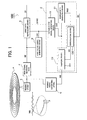
- FIG. 1 shows the main portion of an information reproducing apparatus associated with an embodiment of the present invention.
- This information reproducing apparatus 100 reproduces an information recording medium A thereon.
- the information recording medium A is disc-shaped and can adopt various optical discs, such as a CD, a Compact Disc-Read Only Memory (CD-ROM), a DVD, and a DVD-ROM.
- First data D1 is recorded according to the variable length (i.e., the long or short length) of the record mark.
- the track in close-up, meanders or wobbles in the direction crossing a reading direction. This meandering or wobbling of the track is referred to as the "wobble" and has a shape corresponding to a wobble signal WB.
- the wobble signal WB is obtained by modulating second data D2 in a predetermined modulating method.
- the record mark is formed at a position displaced in the direction crossing the reading direction according to the wobble signal WB.
- the embodiment adopts a spread spectrum modulating method as the predetermined modulating method.
- the first data D1 is synchronized with the second data D2 upon recording.
- the first data D1 is synchronized with the wobble signal WB.
- the information reproducing apparatus 100 is provided with: a reading device E; a read signal generating device F; a wobble signal generating device G; a first data reproducing device B; a second data reproducing device C; and a first clock signal generating device D.
- the reading device E reads the record mark recorded on the information recording medium A.
- the read signal generating device F generates a read signal RF for indicating the long or short length of the record mark on the basis of an output signal from the reading device E.
- the first clock signal generating device D generates a first clock signal DK1 from the read signal RF.
- the read signal RF is a signal obtained by reading the long or short length of the record mark recorded on the information recording medium A.
- the minimum reverse interval of the first data D1 is M times as long as one cycle of the first clock signal CK1.
- the wobble signal generating device G generates the wobble signal WB for indicating the displaced position of the read mark on the basis of the output signal from the reading device E.
- the first data reproducing device B reproduces the first data D1 from the read signal RF by using the first clock signal CK1.
- the second data reproducing device C reproduces the second data D2 by performing predetermined processing using the first clock signal CK1 with respect to the generated wobble signal WB. Namely, it generates the second data D2 from the wobble signal WB by using the first clock signal CK1 reproduced from the long or short length of the record mark.
- it is general to generate a clock signal from a wobble signal. Therefore, it is conceivable to reproduce a clock signal for extracting the second data D2 from the reproduced wobble signal WB.
- the wobble signal WB determines the meandering or wobbling of the track, the frequency thereof is lower than that of the record mark.
- the read signal RF and the wobble signal WB are generated by rotating the disc-shaped information recording medium A upon reproducing. Ideally, it is desirable that there is no eccentricity on the information recording medium A, but actually there is eccentricity to some extent on the information recording medium A. Thus, the read signal RF and the wobble signal WB are influenced by the eccentricity, causing jitter.
- the wobble signal WB is easily influenced by the jitter because of its low frequency, but the read signal RF has a shorter period and a smaller jitter amount because of its high frequency, which increases accuracy as a sampling clock. That is why the second data D2 is generated from the wobble signal WB by using the first clock signal CK1 extracted from the read signal RF. This allows the simplified structure of the information reproducing apparatus 100 and at the same time allows the reproduction of the second data D2 without almost any influence of the eccentricity, thereby drastically improving the error rate of the second data D2.
- the second data reproducing device C is provided with: a random data generating device C1; a second clock signal generating device C2; and a reproducing device C3.
- the random data generating device C1 is provided with a non-volatile memory or the like in which random data RND used for the spread spectrum of the second data D2 is stored.
- the second clock signal generating device C2 generates a second clock signal CK2 synchronized with the first clock signal CK1.
- the second clock signal generating device C2 may have any structure if capable of generating the second clock signal CK2 on the basis of the first clock signal CK1, and may be a Phase Locked Loop (PLL) circuit and a division circuit (e.g., a frequency division circuit), for example.
- PLL Phase Locked Loop
- the division circuit is preferably used from the viewpoint of the simplified structure, and if not, the PLL circuit is preferably used.
- the reproducing device C3 reads the random data RND from the random data generating device C1 by using the second clock signal CK2 and reproduces the second data D2 by demodulating the reproduced wobble signal WB on the basis of the read random data RND.
- the random data RND is read by using the second clock signal CK2 synchronized with the first clock signal CK1.
- the reproducing device C3 is provided with a sampling device C31 and a demodulating device C32.
- the sampling device C31 samples the reproduced wobble signal WB with the second clock signal CK2.
- the demodulating device C32 reproduces the second data D2 by performing an inverse-spread spectrum (i.e., performing a back-spread or reverse-spread spectrum) with respect to the spread spectrum data SS outputted from the sampling device C31, on the basis of the random data RND read from the random data generating device C1 by using the second clock signal CK2.
- the wobble signal WB Since the wobble signal WB has a lower frequency than that of the read signal RF, the inclination of the wobble signal WB near zero crossing is relatively mild. Therefore, if the wobble signal WB is only binarized by a comparator or the like, the jitter amount is large.
- the spread spectrum data SS is extracted by sampling the wobble signal WB with the second clock signal CK2.
- the spread spectrum data SS is obtained by performing the spread spectrum with respect to the second data D2. Since the second clock signal CK2 is generated from the first clock signal CK2 having the high frequency, it is possible to accurately adjust the phase of the second clock signal CK2 with the cycle of the first clock signal CK1.
- the spread spectrum data SS may accurately be extracted from the wobble signal WB by adjusting a timing so as to set the trailing edge of the second clock signal CK2 to the center of the data reverse interval (which is the interval while the data is reverted or inverted) of the wobble signal WB.
- the second clock signal generating device C2 is preferably provided with a frequency-division circuit for 1/N-frequency-dividing the first clock signal CK1 (i.e., for dividing the frequency of the first clock signal CK1 by N, to thereby generate a lower frequency clock as the second clock signal CK2).
- the first data reproducing device B preferably outputs a particular signal obtained by extracting a particular data pattern included in the first data D1, and the division circuit is preferably reset by the particular signal or a signal obtained by delaying the particular signal by a predetermined time length.
- the particular signal may be the synchronization signal SYNC of the first data D1.
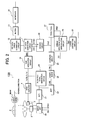
- FIG. 2 shows the structure of the information reproducing apparatus 100.
- pit data DP synchronized with the first clock signal CK1 is recorded by the length (i.e., the long or short length) of the record mark.
- the record mark in this example is a pit, and the track is constructed from a pit row.
- the track has a meandering or wobbling shape corresponding to the wobble signal WB obtained by the spread spectrum modulation of the second data D2.
- the wobble signal WB is synchronized with the second clock signal CK2.
- the first clock signal CK1 has a frequency N times (N: natural number) as large as that of the second clock signal CK2.
- N 250
- the frequency of the second clock signal CK2 is 420 KHz
- the frequency of the first clock signal CK1 is 10.5 MHz.
- the pit data DP corresponds to the first data D1 described above
- the optical disc 1 corresponds to the information recording medium A.
- the information reproducing apparatus 100 is provided with: an optical pickup 2 for irradiating a reproduction beam onto the optical disc 1 and for outputting a signal corresponding to reflected light; a spindle motor 3 for controlling the rotation of the optical disc 1; and a servo unit 22.
- the first clock signal CK1 and the pit synchronization signal SYNC are supplied to the servo unit 22.
- the servo unit 22 performs spindle servo for controlling the rotation of the spindle motor 3 and focus servo and tracking servo for controlling the relative position of the optical pickup 2 with respect to the optical disc 1.
- the optical pickup 2 is provided with: a laser diode for irradiating the reproduction beam; and a four-division detection circuit (not-illustrated).
- the four-division detection circuit divides by 4 the reflected light of the reproduction beam into areas 1A, 1B, 1C, and 1D shown in FIG. 2, and outputs each signal corresponding to the quantity of light in respective one of the areas.
- a head amplifier 4 amplifies each output signal of the optical pickup 2, and outputs a divisional read signal 1a corresponding to the area 1A, a divisional read signal 1b corresponding to the area 1B, a divisional read signal 1c corresponding to the area 1C, and a divisional read signal 1d corresponding to the area 1D.
- the optical pickup 2 and the head amplifier 4 correspond to the reading device E described above.
- a sum generation circuit 10 corresponds to the read signal generating device F and is constructed from an addition circuit for adding the divisional read signals 1a, 1b, 1c, and 1d and for outputting a sum read signal SRF.
- the sum read signal SRF represents the length (i.e., the long or short length) of the record mark and corresponds to the read signal RF described above.
- a pit data generation circuit 11 reproduces the pit data DP and generates the first clock signal CK1 on the basis of the sum read signal SRF.
- the pit data generation circuit 11 corresponds to the first data reproducing device B and the first clock signal generating device D described above.
- FIG. 3 shows the structure of the pit data generation circuit 11. As shown in FIG. 3, the pit data generation circuit 11 is provided with: a first clock signal reproduction circuit 111; a pit data extraction circuit 112; a synchronization signal detection circuit 113; a pit data demodulation circuit 114; and a descrambler circuit 115.
- the first clock signal reproduction circuit 111 reproduces the first clock signal CK1 synchronized with the pit data DP on the basis of the sum read signal SRF.
- the pit data extraction circuit 112 samples, with the first clock signal CK1, a binary signal obtained by binarizing the sum read signal SRF and reproduces the pit data DP.
- the synchronization signal detection circuit 113 detects a synchronization pattern included in the reproduced pit data DP and generates the pit synchronization signal SYNC.
- the synchronization pattern is a particular data pattern which is not included in other pit data, and has a constant cycle.
- the pit synchronization signal SYNC indicates the timing of the synchronization pattern.
- the pit synchronization signal SYNC in this example is active (at a low level) only in one cycle of the first clock signal CK1 from the beginning of the synchronization pattern.
- the pit data demodulation circuit 114 generates reproduction data by demodulating the reproduced pit data DP with a predetermined table, with the pit synchronization signal SYNC being as a reference position. For example, if Eight to Fourteen Modulation (EFM) is used as a modulating method, the demodulation processing is performed in which 14 bits of the pit data DP is converted into 8 bits of the reproduction data.
- the descrambler circuit 115 performs descrambling in which the order of the reproduction data is rearranged according to a preset rule, and outputs the processed reproduction data.
- the reproduction data as obtained above is supplied to a pit data error correction circuit 12 shown in FIG. 2, and after error correcting and interpolating therein, it is stored into a buffer 13.
- An interface 14 sequentially reads the data stored in the buffer 13, converts it into a predetermined output form, and outputs it to external equipment.
- a push-pull signal generation circuit 20 calculates (1a + 1d) - (1b + 1c) and generates a push-pull signal.
- the component (1a + 1d) corresponds to the areas 1A and 1D which are on the left side with respect to the reading direction, while the component (1b + 1c) corresponds to the areas 1B and 1C which are on the right side with respect to the reading direction.
- the push-pull signal will have positive polarity with the amplitude center thereof as a standard. If the reproduction beam is positioned in the center of the pit, the value of the push-pull signal will be in the amplitude center thereof.
- the push-pull signal will have negative polarity with the amplitude center thereof as a standard.
- the relative position between the reproduction beam and the pit changes according to the meandering of the track, and the value of the push-pull signal represents the relative position between the reproduction beam and the pit.
- the push-pull signal is a signal corresponding to the meandering of the track.
- the push-pull signal is outputted through a low pass filter 21 to the servo unit 22.
- the servo unit 22 performs tracking control on the basis of the push-pull signal.
- the push-pull signal is supplied to a band pass filter 23.
- the pass band of the band pass filter 23 is set to extract the wobble signal WB obtained by the spread spectrum modulation of the second data D2 upon recording from the push-pull signal. Therefore, the band pass filter 23 constitutes the wobble signal generating device G described above with the push-pull signal generation circuit 20, and the output signal thereof is such as to reproduce the wobble signal WB from the optical disc 1.
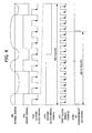
- FIG. 4 shows the relationship among the wobble signal WB, a binary signal 24a, the first clock signal CK1, the second clock signal CK2, and the pit synchronization signal SYNC.
- the comparator 24 outputs the binary signal 24a obtained by binarizing the wobble signal WB. Since the wobble signal WB has a low frequency, the inclination thereof near zero crossing is relatively mild. Thus, the binary signal 24a has a large jitter component.
- the sampling circuit 25 samples the binary signal 24a by using the second clock signal CK2 and reproduces the spread spectrum data SS by extracting the data.
- the frequency f1 of the first clock signal CK1 is 10.5 MHz and the frequency f2 of the second clock signal CK2 is 420 KHz.
- the first clock signal CK1 has a frequency 250 times as large as that of the second clock signal CK2.
- the division circuit 26 generates the second clock signal CK2 by frequency-dividing the first clock signal CK1 by 250. Therefore, as shown in FIG. 4, one cycle of the second clock signal CK2 can contain therein 250 first clock signals CK1.
- the division circuit 26 is set to be reset if the voltage of a reset terminal R is active (at a low level), and the pit synchronization signal SYNC is supplied to the reset terminal R. Therefore, the second clock signal CK2 is reset by the trailing edge of the pit synchronization signal SYNC, and its phase is determined from the pit synchronization signal SYNC.
- the synchronization patterns are inserted in the pit data DP with a period of 250*K (K: natural number) bits, and each has such a relationship that the beginning of the synchronization pattern agrees with the leading or rising edge of the second clock signal CK2. Namely, the synchronization pattern has a frequency which is a natural multiple of that of the second clock signal CK2.
- the division circuit 26 is reset and the phases of the pit synchronization signal SYNC and the second clock signal CK2 are adjusted. This makes it possible to set the trailing edge of the second clock signal CK2 to the center of the data minimum reverse interval of the binary signal 24a. Therefore, even if the edge of the binary signal 24a is influenced and wobbled by jitter, it is possible to certainly extract the spread spectrum data SS.
- a random pattern used for the spread spectrum modulation upon recording is stored on a RAND table 27.
- the random pattern corresponds to a spread code and is a bit row generated by using a random function.
- the second clock signal CK2 is supplied to the RAND table 27.
- the random data RND is generated.
- the generated random data RND is supplied to a spread spectrum data demodulation circuit 28.
- the spread spectrum data SS outputted from the sampling circuit 25 is also supplied to the spread spectrum data demodulation circuit 28.
- the division circuit 26 corresponds to the second clock signal generating device C2.
- the comparator 24 and the sampling circuit 25 correspond to the sampling device C31.
- the spread spectrum data demodulation circuit 28 corresponds to the demodulating device C32.
- the RAND table 27 corresponds to the random data generating device C1.
- FIG. 5 shows the relationship among the spread spectrum data SS, the random data RND, and the second data D2.
- the spread spectrum data demodulation circuit 28 is constructed from a multiplication circuit (e.g. an eXclusive OR (XOR) circuit) and reproduces the second data D2 by multiplying the spread spectrum data SS and the random data RND. In this case, a signal which is not in an original signal band is converted into a signal which is out of the band by the multiplication.
- the second data D2 reproduced in this manner is outputted after error correcting on the error correction circuit 29.
- the sampling circuit 25 samples the binary signal 24a with the second clock signal CK2 and reproduces the spread spectrum data SS, but instead of the second clock signal CK2, the first clock signal CK1 may be used for the sampling, and data after the sampling may be corrected.
- the sampling circuit 25 may supply the data after the sampling to the spread spectrum data demodulation circuit, demodulate the spread spectrum, and then correct it by using the second clock signal CK2 or the like.
- the point is any method may be used if the second data D2 is reproduced by performing predetermined processing using the first clock signal CK1 with respect to the wobble signal WB reproduced from the optical disc 1 as being the information recording medium A.
- the second data D2 with respect to which the spread spectrum is performed is recorded onto the information recording medium A
- it is also possible to prepare a plurality of random patterns select one of the plurality of random patterns according to a predetermined rule, generate the wobble signal WB by the spread spectrum modulation of the second data D2 by using the selected random pattern, and form the record mark at a displaced position, to which it is displaced in the direction crossing the reading direction according to the generated wobble signal WB.
- the second data D2 is reproduced from such an information recording medium A, what is needed is to prepare a plurality of RAND tables 27 and demodulate the spread spectrum data SS by using the random data RND selectively read from the RAND tables 27 according to a predetermined rule.
- the division circuit 26 may be reset in the following manner. Namely, if the pit synchronization signal SYNC becomes active, a counter for starting to count the first clock signals CK1 and a comparison circuit for comparing the counted value of the counter with the predetermined number may be provided, and the division circuit 26 may be reset at a timing at which the agreement is detected on the comparison circuit. In this case, the division circuit 26 is reset by a signal obtained by delaying the pit synchronization signal SYNC by a predetermined time length.
- the present invention may be such as to extract a particular data pattern from the pit data DP and adjust the phase of the second clock signal CK2 on the basis of a particular signal (synchronization signal) extracted upon reproducing, and is preferably such as to adjust it by the unit of one period of the first clock signal CK1.
- the second data D2 is reproduced from the information recording medium A on which the pit data DP is recorded according to the length (i.e., the long or short length) of the record mark and on which the record mark is formed at a displaced position to which it is displaced in the direction crossing the reading direction according to the wobble signal WB obtained by the modulation of the second data D2 in a predetermined modulating method
- the first clock signal CK1 synchronized with the pit data DP is reproduced from a signal obtained by reading the long or short length of the record mark and this first clock signal CK1 is used to reproduce the second data D2. Therefore, it is possible to make it unnecessary to generate the second clock signal CK2 from the reproduced wobble signal WB and at the same time it is possible to accurately extract the spread spectrum data SS, and thus it is possible to drastically decrease the error rate of the second data D2.
Landscapes
- Engineering & Computer Science (AREA)
- Signal Processing (AREA)
- Computer Security & Cryptography (AREA)
- Optical Recording Or Reproduction (AREA)
- Signal Processing For Digital Recording And Reproducing (AREA)
- Optical Record Carriers And Manufacture Thereof (AREA)
Abstract
Description
Claims (9)
- An information reproducing apparatus (100) for reproducing information recorded on an information recording medium (A), on which a record mark having a variable length according to first data (D1) is formed at a displaced position to which the record mark is displaced in a direction crossing a reading direction of the record mark according to a wobble signal (WB) obtained by modulating second data (D2) in a predetermined modulating method,
characterized in that said information reproducing apparatus comprises:a reading device (E) for reading the record mark recorded on said information recording medium;a read signal generating device (F) for generating a read signal (RF) for indicating the length of the record mark on the basis of an output signal from said reading device;a first clock signal generating device (D) for generating a first clock signal (CK1) on the basis of the read signal;a wobble signal generating device (G) for generating a wobble signal for indicating the displaced position of the read mark on the basis of the output signal from said reading device; anda second data reproducing device (C) for reproducing the second data from the generated wobble signal by using the first clock signal. - The information reproducing apparatus according to claim 1,
characterized in that said information reproducing apparatus further comprises a first data reproducing device (B) for reproducing the first data (D1) from the read signal (RF) by using the first clock signal (CK1). - The information reproducing apparatus according to claim 2, characterized in that the predetermined modulating method is a spread spectrum method.
- The information reproducing apparatus according to claim 3, characterized in that said second data reproducing device (C) comprises:a second clock signal generating device (C2) for generating a second clock signal (CK2) synchronized with the first clock signal (CK1);a random data generating device (C1) for generating random data (RND) used for the spread spectrum modulation of the second data (D2) by using the second clock signal; anda random-data-based reproducing device (C3) for reproducing the second data by demodulating the generated wobble signal (WB) on the basis of the generated random data.
- The information reproducing apparatus according to claim 4, characterized in that said random-data-based reproducing device (C3) comprises:a sampling device (C31) for sampling the generated wobble signal (WB) by using the second clock signal; anda demodulating device (C32) for reproducing the second data (D2) by performing an inverse-spread spectrum with respect to an output data of said sampling device by using the generated random data (RND).
- The information reproducing apparatus according to claim 4, characterized in that
a data rate of the first data (D1) is N times (N: natural number, N ≧ 2) as large as that of the random data (RND), and
said second clock signal generating device (C2) comprises a frequency-division circuit for 1/N-frequency-dividing the first clock signal (CK1). - The information reproducing apparatus according to claim 6, characterized in that
said first data reproducing device (B) outputs a particular signal obtained by extracting a particular data pattern included in the first data (D1), and
the frequency-division circuit is reset by the particular signal or a signal obtained by delaying the particular signal by a predetermined time length. - The information reproducing apparatus according to claim 7, characterized in that the particular signal is a synchronization signal (SYNC).
- An information reproducing method of reproducing information recorded on an information recording medium (A), on which a record mark having a variable length according to first data (D1) is formed at a displaced position to which the record mark is displaced in a direction crossing a reading direction of the record mark according to a wobble signal (WB) obtained by modulating second data (D2) in a predetermined modulating method,
characterized in that said information reproducing method comprises:a reading process of reading the record mark recorded on said information recording medium;a read signal generating process of generating a read signal (RF) for indicating the length of the record mark on the basis of an output signal read by said reading process;a first clock signal generating process of generating a first clock signal (CK1) on the basis of the read signal;a wobble signal generating process of generating a wobble signal for indicating the displaced position of the read mark on the basis of the output signal read by said reading process; anda second data reproducing process of reproducing the second data from the generated wobble signal by using the first clock signal.
Applications Claiming Priority (2)
| Application Number | Priority Date | Filing Date | Title |
|---|---|---|---|
| JP2003147941 | 2003-05-26 | ||
| JP2003147941A JP4063713B2 (en) | 2003-05-26 | 2003-05-26 | Information reproducing apparatus and information reproducing method |
Publications (3)
| Publication Number | Publication Date |
|---|---|
| EP1482502A2 true EP1482502A2 (en) | 2004-12-01 |
| EP1482502A3 EP1482502A3 (en) | 2006-04-05 |
| EP1482502B1 EP1482502B1 (en) | 2017-10-25 |
Family
ID=33128202
Family Applications (1)
| Application Number | Title | Priority Date | Filing Date |
|---|---|---|---|
| EP04252914.9A Expired - Lifetime EP1482502B1 (en) | 2003-05-26 | 2004-05-19 | Information reproducing apparatus and method |
Country Status (4)
| Country | Link |
|---|---|
| US (2) | US7301866B2 (en) |
| EP (1) | EP1482502B1 (en) |
| JP (1) | JP4063713B2 (en) |
| CN (1) | CN1300784C (en) |
Families Citing this family (4)
| Publication number | Priority date | Publication date | Assignee | Title |
|---|---|---|---|---|
| US20040105366A1 (en) * | 2002-09-11 | 2004-06-03 | Samsung Electronics Co., Ltd. | Information storage medium, and data recording, reproducing, detecting and/or evaluating apparatus and method using the same |
| US7978589B1 (en) * | 2007-08-06 | 2011-07-12 | Marvell International Ltd. | System and method for verifying write performance during optical recording |
| EP2385526A1 (en) * | 2009-01-16 | 2011-11-09 | Sharp Kabushiki Kaisha | Optical information recording medium and device for recording/reproducing information on/from optical information recording medium |
| WO2011007841A1 (en) * | 2009-07-17 | 2011-01-20 | シャープ株式会社 | Optical information recording medium |
Family Cites Families (14)
| Publication number | Priority date | Publication date | Assignee | Title |
|---|---|---|---|---|
| DE69230168T2 (en) | 1991-12-02 | 2000-04-20 | Koninklijke Philips Electronics N.V. | Closed information system with copy protection |
| JPH0845188A (en) * | 1994-07-29 | 1996-02-16 | Sony Corp | Recording medium, recording apparatus and reproducing apparatus therefor |
| JPH08293157A (en) | 1995-04-21 | 1996-11-05 | Matsushita Electric Ind Co Ltd | Recording / reproducing method for variable frame length high efficiency coded data |
| JP4098929B2 (en) * | 1999-09-01 | 2008-06-11 | パイオニア株式会社 | Information recording medium, medium manufacturing apparatus, information detecting apparatus, and information recording apparatus |
| JP2001216650A (en) | 2000-01-28 | 2001-08-10 | Sony Corp | Recording method, disk manufacturing apparatus and recording medium |
| JP2002042413A (en) * | 2000-05-18 | 2002-02-08 | Sony Corp | Data recording medium, data recording method and device, data reproducing method and device, data recording and reproducing method and device, data transmitting method and device, data receiving method and device, content data |
| US7002895B1 (en) * | 2000-11-18 | 2006-02-21 | Hewlett-Packard Development Company, L.P. | Optical disk having zone constant angular velocity wobble |
| JP2002237138A (en) * | 2000-12-04 | 2002-08-23 | Hitachi Ltd | Data playback device |
| KR100719129B1 (en) * | 2001-02-06 | 2007-05-17 | 삼성전자주식회사 | Disc player |
| JP4220722B2 (en) | 2001-05-02 | 2009-02-04 | パイオニア株式会社 | Information recording medium and information reading apparatus |
| ATE401647T1 (en) * | 2001-05-02 | 2008-08-15 | Pioneer Corp | INFORMATION RECORDING MEDIUM AND INFORMATION RECORDING DEVICE |
| KR100708110B1 (en) * | 2001-06-23 | 2007-04-16 | 삼성전자주식회사 | System clock generating device using wobble signal and data reproducing device using the same |
| EP1293971B1 (en) * | 2001-09-14 | 2008-07-16 | Pioneer Corporation | Information recording medium, information reading apparatus and information recording apparatus |
| JP4467849B2 (en) | 2001-09-14 | 2010-05-26 | パイオニア株式会社 | Information recording medium, information reading device, and information recording device |
-
2003
- 2003-05-26 JP JP2003147941A patent/JP4063713B2/en not_active Expired - Fee Related
-
2004
- 2004-05-19 EP EP04252914.9A patent/EP1482502B1/en not_active Expired - Lifetime
- 2004-05-25 US US10/852,487 patent/US7301866B2/en not_active Expired - Fee Related
- 2004-05-26 CN CNB2004100459697A patent/CN1300784C/en not_active Expired - Fee Related
-
2007
- 2007-10-11 US US11/907,345 patent/US7701816B2/en not_active Expired - Fee Related
Also Published As
| Publication number | Publication date |
|---|---|
| CN1300784C (en) | 2007-02-14 |
| US20080043589A1 (en) | 2008-02-21 |
| JP2004348924A (en) | 2004-12-09 |
| CN1573958A (en) | 2005-02-02 |
| EP1482502A3 (en) | 2006-04-05 |
| US7301866B2 (en) | 2007-11-27 |
| US7701816B2 (en) | 2010-04-20 |
| US20040240363A1 (en) | 2004-12-02 |
| JP4063713B2 (en) | 2008-03-19 |
| EP1482502B1 (en) | 2017-10-25 |
Similar Documents
| Publication | Publication Date | Title |
|---|---|---|
| JP3850600B2 (en) | Information recording disk and information recording apparatus | |
| US7701816B2 (en) | Information reproducing apparatus and method | |
| JP3881835B2 (en) | Recording / playback device | |
| EP1255246A2 (en) | Information recording medium and information reading apparatus | |
| US20080025171A1 (en) | Information recording medium, and information reproducing apparatus and method | |
| JP3714117B2 (en) | Pre-pit detection device, pre-pit detection method, position and frequency signal detection circuit | |
| EP1494223B1 (en) | Information recording medium, and information reproducing apparatus and method | |
| JP4220722B2 (en) | Information recording medium and information reading apparatus | |
| US7522503B2 (en) | Information recording medium having first and second synchronization signals recorded thereon, and information reproducing apparatus and method | |
| KR100682365B1 (en) | Sync signal detecting device and sync signal detecting method | |
| JP3561259B2 (en) | Information storage medium, information recording device, information reproducing device, information recording method, and information reproducing method | |
| US7330416B2 (en) | Information recording medium having first data which has been displaced according to second data, and information reproducing apparatus and method | |
| US7447142B2 (en) | Information recording medium and information recording/reproducing apparatus | |
| US7333415B2 (en) | Information recording medium having first data which has been displaced according to second data, and information reproducing apparatus and method | |
| US20050018564A1 (en) | Information recording medium, and information reproducing apparatus and method | |
| US20050078576A1 (en) | Information recording medium, information recording/reproducing apparatus and information reproducing method | |
| JP2008140463A (en) | Wobble signal detection circuit and wobble signal detection method | |
| JP2004319089A (en) | Prepit detection device and prepit detection method | |
| JP2005196968A (en) | Information recording disk and information recording disk reproducing device |
Legal Events
| Date | Code | Title | Description |
|---|---|---|---|
| PUAI | Public reference made under article 153(3) epc to a published international application that has entered the european phase |
Free format text: ORIGINAL CODE: 0009012 |
|
| AK | Designated contracting states |
Kind code of ref document: A2 Designated state(s): AT BE BG CH CY CZ DE DK EE ES FI FR GB GR HU IE IT LI LU MC NL PL PT RO SE SI SK TR |
|
| AX | Request for extension of the european patent |
Extension state: AL HR LT LV MK |
|
| PUAL | Search report despatched |
Free format text: ORIGINAL CODE: 0009013 |
|
| AK | Designated contracting states |
Kind code of ref document: A3 Designated state(s): AT BE BG CH CY CZ DE DK EE ES FI FR GB GR HU IE IT LI LU MC NL PL PT RO SE SI SK TR |
|
| AX | Request for extension of the european patent |
Extension state: AL HR LT LV MK |
|
| 17P | Request for examination filed |
Effective date: 20060925 |
|
| AKX | Designation fees paid |
Designated state(s): DE FR GB |
|
| RAP1 | Party data changed (applicant data changed or rights of an application transferred) |
Owner name: PIONEER CORPORATION |
|
| 17Q | First examination report despatched |
Effective date: 20150901 |
|
| RAP1 | Party data changed (applicant data changed or rights of an application transferred) |
Owner name: PIONEER CORPORATION |
|
| GRAP | Despatch of communication of intention to grant a patent |
Free format text: ORIGINAL CODE: EPIDOSNIGR1 |
|
| INTG | Intention to grant announced |
Effective date: 20170519 |
|
| GRAS | Grant fee paid |
Free format text: ORIGINAL CODE: EPIDOSNIGR3 |
|
| GRAA | (expected) grant |
Free format text: ORIGINAL CODE: 0009210 |
|
| AK | Designated contracting states |
Kind code of ref document: B1 Designated state(s): DE FR GB |
|
| REG | Reference to a national code |
Ref country code: GB Ref legal event code: FG4D Ref country code: DE Ref legal event code: R084 Ref document number: 602004051941 Country of ref document: DE |
|
| REG | Reference to a national code |
Ref country code: DE Ref legal event code: R096 Ref document number: 602004051941 Country of ref document: DE |
|
| REG | Reference to a national code |
Ref country code: FR Ref legal event code: PLFP Year of fee payment: 15 |
|
| REG | Reference to a national code |
Ref country code: DE Ref legal event code: R097 Ref document number: 602004051941 Country of ref document: DE |
|
| PGFP | Annual fee paid to national office [announced via postgrant information from national office to epo] |
Ref country code: FR Payment date: 20180522 Year of fee payment: 15 |
|
| PLBE | No opposition filed within time limit |
Free format text: ORIGINAL CODE: 0009261 |
|
| STAA | Information on the status of an ep patent application or granted ep patent |
Free format text: STATUS: NO OPPOSITION FILED WITHIN TIME LIMIT |
|
| 26N | No opposition filed |
Effective date: 20180726 |
|
| PGFP | Annual fee paid to national office [announced via postgrant information from national office to epo] |
Ref country code: DE Payment date: 20180522 Year of fee payment: 15 Ref country code: GB Payment date: 20180518 Year of fee payment: 15 |
|
| REG | Reference to a national code |
Ref country code: DE Ref legal event code: R119 Ref document number: 602004051941 Country of ref document: DE |
|
| GBPC | Gb: european patent ceased through non-payment of renewal fee |
Effective date: 20190519 |
|
| PG25 | Lapsed in a contracting state [announced via postgrant information from national office to epo] |
Ref country code: DE Free format text: LAPSE BECAUSE OF NON-PAYMENT OF DUE FEES Effective date: 20191203 Ref country code: GB Free format text: LAPSE BECAUSE OF NON-PAYMENT OF DUE FEES Effective date: 20190519 |
|
| PG25 | Lapsed in a contracting state [announced via postgrant information from national office to epo] |
Ref country code: FR Free format text: LAPSE BECAUSE OF NON-PAYMENT OF DUE FEES Effective date: 20190531 |