EP1482386A2 - Power window apparatus - Google Patents
Power window apparatus Download PDFInfo
- Publication number
- EP1482386A2 EP1482386A2 EP04252312A EP04252312A EP1482386A2 EP 1482386 A2 EP1482386 A2 EP 1482386A2 EP 04252312 A EP04252312 A EP 04252312A EP 04252312 A EP04252312 A EP 04252312A EP 1482386 A2 EP1482386 A2 EP 1482386A2
- Authority
- EP
- European Patent Office
- Prior art keywords
- terminal
- switch
- window apparatus
- connector
- power window
- Prior art date
- Legal status (The legal status is an assumption and is not a legal conclusion. Google has not performed a legal analysis and makes no representation as to the accuracy of the status listed.)
- Granted
Links
Images



Classifications
-
- H—ELECTRICITY
- H01—ELECTRIC ELEMENTS
- H01R—ELECTRICALLY-CONDUCTIVE CONNECTIONS; STRUCTURAL ASSOCIATIONS OF A PLURALITY OF MUTUALLY-INSULATED ELECTRICAL CONNECTING ELEMENTS; COUPLING DEVICES; CURRENT COLLECTORS
- H01R13/00—Details of coupling devices of the kinds covered by groups H01R12/70 or H01R24/00 - H01R33/00
- H01R13/46—Bases; Cases
- H01R13/52—Dustproof, splashproof, drip-proof, waterproof, or flameproof cases
-
- B—PERFORMING OPERATIONS; TRANSPORTING
- B42—BOOKBINDING; ALBUMS; FILES; SPECIAL PRINTED MATTER
- B42D—BOOKS; BOOK COVERS; LOOSE LEAVES; PRINTED MATTER CHARACTERISED BY IDENTIFICATION OR SECURITY FEATURES; PRINTED MATTER OF SPECIAL FORMAT OR STYLE NOT OTHERWISE PROVIDED FOR; DEVICES FOR USE THEREWITH AND NOT OTHERWISE PROVIDED FOR; MOVABLE-STRIP WRITING OR READING APPARATUS
- B42D1/00—Books or other bound products
- B42D1/009—Books or other bound products characterised by printed matter not otherwise provided for
-
- B—PERFORMING OPERATIONS; TRANSPORTING
- B42—BOOKBINDING; ALBUMS; FILES; SPECIAL PRINTED MATTER
- B42D—BOOKS; BOOK COVERS; LOOSE LEAVES; PRINTED MATTER CHARACTERISED BY IDENTIFICATION OR SECURITY FEATURES; PRINTED MATTER OF SPECIAL FORMAT OR STYLE NOT OTHERWISE PROVIDED FOR; DEVICES FOR USE THEREWITH AND NOT OTHERWISE PROVIDED FOR; MOVABLE-STRIP WRITING OR READING APPARATUS
- B42D15/00—Printed matter of special format or style not otherwise provided for
-
- E—FIXED CONSTRUCTIONS
- E05—LOCKS; KEYS; WINDOW OR DOOR FITTINGS; SAFES
- E05F—DEVICES FOR MOVING WINGS INTO OPEN OR CLOSED POSITION; CHECKS FOR WINGS; WING FITTINGS NOT OTHERWISE PROVIDED FOR, CONCERNED WITH THE FUNCTIONING OF THE WING
- E05F15/00—Power-operated mechanisms for wings
- E05F15/40—Safety devices, e.g. detection of obstructions or end positions
-
- E—FIXED CONSTRUCTIONS
- E05—LOCKS; KEYS; WINDOW OR DOOR FITTINGS; SAFES
- E05F—DEVICES FOR MOVING WINGS INTO OPEN OR CLOSED POSITION; CHECKS FOR WINGS; WING FITTINGS NOT OTHERWISE PROVIDED FOR, CONCERNED WITH THE FUNCTIONING OF THE WING
- E05F15/00—Power-operated mechanisms for wings
- E05F15/60—Power-operated mechanisms for wings using electrical actuators
- E05F15/603—Power-operated mechanisms for wings using electrical actuators using rotary electromotors
- E05F15/665—Power-operated mechanisms for wings using electrical actuators using rotary electromotors for vertically-sliding wings
- E05F15/689—Power-operated mechanisms for wings using electrical actuators using rotary electromotors for vertically-sliding wings specially adapted for vehicle windows
- E05F15/695—Control circuits therefor
-
- E—FIXED CONSTRUCTIONS
- E05—LOCKS; KEYS; WINDOW OR DOOR FITTINGS; SAFES
- E05Y—INDEXING SCHEME ASSOCIATED WITH SUBCLASSES E05D AND E05F, RELATING TO CONSTRUCTION ELEMENTS, ELECTRIC CONTROL, POWER SUPPLY, POWER SIGNAL OR TRANSMISSION, USER INTERFACES, MOUNTING OR COUPLING, DETAILS, ACCESSORIES, AUXILIARY OPERATIONS NOT OTHERWISE PROVIDED FOR, APPLICATION THEREOF
- E05Y2800/00—Details, accessories and auxiliary operations not otherwise provided for
- E05Y2800/40—Physical or chemical protection
- E05Y2800/428—Physical or chemical protection against water or ice
-
- E—FIXED CONSTRUCTIONS
- E05—LOCKS; KEYS; WINDOW OR DOOR FITTINGS; SAFES
- E05Y—INDEXING SCHEME ASSOCIATED WITH SUBCLASSES E05D AND E05F, RELATING TO CONSTRUCTION ELEMENTS, ELECTRIC CONTROL, POWER SUPPLY, POWER SIGNAL OR TRANSMISSION, USER INTERFACES, MOUNTING OR COUPLING, DETAILS, ACCESSORIES, AUXILIARY OPERATIONS NOT OTHERWISE PROVIDED FOR, APPLICATION THEREOF
- E05Y2800/00—Details, accessories and auxiliary operations not otherwise provided for
- E05Y2800/67—Materials; Strength alteration thereof
- E05Y2800/68—Combinations of materials creating distinct article parts
-
- E—FIXED CONSTRUCTIONS
- E05—LOCKS; KEYS; WINDOW OR DOOR FITTINGS; SAFES
- E05Y—INDEXING SCHEME ASSOCIATED WITH SUBCLASSES E05D AND E05F, RELATING TO CONSTRUCTION ELEMENTS, ELECTRIC CONTROL, POWER SUPPLY, POWER SIGNAL OR TRANSMISSION, USER INTERFACES, MOUNTING OR COUPLING, DETAILS, ACCESSORIES, AUXILIARY OPERATIONS NOT OTHERWISE PROVIDED FOR, APPLICATION THEREOF
- E05Y2900/00—Application of doors, windows, wings or fittings thereof
- E05Y2900/50—Application of doors, windows, wings or fittings thereof for vehicles
- E05Y2900/53—Type of wing
- E05Y2900/55—Windows
-
- H—ELECTRICITY
- H01—ELECTRIC ELEMENTS
- H01R—ELECTRICALLY-CONDUCTIVE CONNECTIONS; STRUCTURAL ASSOCIATIONS OF A PLURALITY OF MUTUALLY-INSULATED ELECTRICAL CONNECTING ELEMENTS; COUPLING DEVICES; CURRENT COLLECTORS
- H01R12/00—Structural associations of a plurality of mutually-insulated electrical connecting elements, specially adapted for printed circuits, e.g. printed circuit boards [PCB], flat or ribbon cables, or like generally planar structures, e.g. terminal strips, terminal blocks; Coupling devices specially adapted for printed circuits, flat or ribbon cables, or like generally planar structures; Terminals specially adapted for contact with, or insertion into, printed circuits, flat or ribbon cables, or like generally planar structures
- H01R12/70—Coupling devices
- H01R12/71—Coupling devices for rigid printing circuits or like structures
- H01R12/72—Coupling devices for rigid printing circuits or like structures coupling with the edge of the rigid printed circuits or like structures
- H01R12/722—Coupling devices for rigid printing circuits or like structures coupling with the edge of the rigid printed circuits or like structures coupling devices mounted on the edge of the printed circuits
- H01R12/724—Coupling devices for rigid printing circuits or like structures coupling with the edge of the rigid printed circuits or like structures coupling devices mounted on the edge of the printed circuits containing contact members forming a right angle
-
- H—ELECTRICITY
- H01—ELECTRIC ELEMENTS
- H01R—ELECTRICALLY-CONDUCTIVE CONNECTIONS; STRUCTURAL ASSOCIATIONS OF A PLURALITY OF MUTUALLY-INSULATED ELECTRICAL CONNECTING ELEMENTS; COUPLING DEVICES; CURRENT COLLECTORS
- H01R2201/00—Connectors or connections adapted for particular applications
- H01R2201/26—Connectors or connections adapted for particular applications for vehicles
Definitions
- the present invention relates to a power window apparatus, and more particularly, to a power window apparatus in which a switch board and a control board are connected via a connector.
- a power window apparatus which raises and lowers a window glass with a direct current (DC) motor
- DC direct current
- an operation switch is first operated by an operator, so that a motor electronic control unit (motor ECU), which is electrically connected to the operation switch, controls the motor according to an input signal from the operation switch. Torque produced by the motor is then transmitted to the window glass via a mechanical structure, to raise or lower the window glass.
- motor ECU motor electronic control unit
- a board on which the motor ECU is mounted may have a waterproof structure shown, for example, in Japanese Laid-Open Patent Publication No. 2002-13964, to prevent water entry when the vehicle is submerged in water.
- a board, on which an operation switch (switch unit) is mounted, and a motor controller are connected via a connector.
- the connector is arranged on the board of the switch unit, however, the connected parts of the connector and the switch unit often do not have a waterproof structure. If this power window apparatus is submerged in water, water enters into the connected parts of the connector and the switch unit. Such water entry causes leakage current to flow between terminals of the connector. The leakage current may cause the motor ECU to incorrectly recognize its input signal. Particularly, when the motor ECU drives the motor to raise or lower the window glass in response to a low-level input signal (active-low control), the motor ECU may incorrectly recognize its input signal due to water entry.
- a pull-up resistor is connected to each input terminal of the motor ECU.
- this power window apparatus When, for example, this power window apparatus is submerged in water, water enters into the connected parts of the connector and the switch unit. If this happens, leakage current flows between a terminal for an input signal and a ground terminal. The resistance of a leakage resistor between the two terminals is smaller than the resistance of the pull-up resistor connected to the input terminal.
- the motor ECU detects a low-level potential like when the operation switch is closed. This causes the motor ECU to incorrectly recognize that the operation switch is closed when the operation switch is not operated.
- the present invention provides a power window apparatus that inhibits leakage current when submerged in water.
- the prevent invention provides a power window apparatus for moving a window glass of a vehicle by driving an actuator.
- the power window apparatus includes a switch operated to cause the window glass to move.
- a control unit controls the actuator.
- a connector has a connecting terminal connecting the switch and the control unit.
- the connector has a ground terminal used to connect the switch to ground.
- the switch connects the connecting terminal and the ground terminal to each other and generates a switch signal having a ground level at the connecting terminal when the switch is operated.
- the control unit drives the actuator in response to the switch signal having the ground level.
- An inhibiting means arranged in the connector inhibits leakage current from flowing between the connecting terminal and the ground terminal when the connector is submerged in water.
- a further embodiment of the present invention is a power window apparatus for moving a window glass of a vehicle by driving an actuator.
- the power window apparatus is connected to a power supply.
- the power window apparatus includes a switch operated for generating a switch signal to cause the window glass to move.
- a control unit controls the actuator.
- the control unit includes an input terminal that is provided with the switch signal.
- a resistor is connected between the power supply and the input terminal of the control unit.
- a connector has a connecting terminal connecting the switch and the input terminal of the control unit.
- the connector has a ground terminal used to connect the switch to ground.
- the switch connects the connecting terminal and the ground terminal to each other and generates a switch signal having a ground level at the connecting terminal when the switch is operated.
- the control unit drives the actuator in response to the switch signal having the ground level.
- the connector includes a power supply terminal connected to the power supply and arranged between the connecting terminal and the ground terminal.
- a power window apparatus 1 according to a preferred embodiment of the present invention will now be described with reference to Figs. 1 to 5.
- the power window apparatus 1 includes a switch unit 11 and a motor controller 12, which has a waterproof structure.
- the switch unit 11 includes a board 25, an operation switch 10 connected to the board 25, and a connector 13 mounted on the board 25.
- the switch unit 11 and the motor controller 12 are connected by a wire harness 14 via the connector 13.
- a down terminal 17, a ground terminal 18, an up terminal 19, and battery terminals 20 of the switch unit 11 are arranged in the connector 13.
- the operation switch 10 includes a lowering switch 15 and a raising switch 16.
- the lowering switch 15 has a first terminal connected to the down terminal 17 and a second terminal connected to the ground terminal 18.
- the raising switch 16 has a first terminal connected to the up terminal 19, and a second terminal connected to the ground terminal 18.
- either the lowering switch 15 or the raising switch 16 is closed by operating a button (not shown).
- the down terminal 17 connects to the ground terminal 18 via the closed lowering switch 15.
- the up terminal 19 connects to the ground terminal 18 via the closed raising switch 16.
- a power supply Vo (12V) is connected to the battery terminals (high-level terminals) 20.
- the switch unit 11 includes electronic components such as LEDs (not shown) connected to the battery terminals 20 and the ground terminal 18.
- the electronic components operate using power supplied from the power supply Vo.
- the high-level signals transmitted via the battery terminals 20 include high-level signals other than those signals having the same potential level as the power supply Vo described in the preferred embodiment.
- the ground terminal 18 of the switch unit 11 is grounded. When the lowering switch 15 is closed by operating the operation switch 10, the down terminal 17 is grounded via the closed lowering switch 15 and the ground terminal 18. When the raising switch 16 is closed by operating the operation switch 10, the up terminal 19 is grounded via the closed raising switch 16 and the ground terminal 18.
- the switch unit 11 is connected to the motor controller 12 via the wire harness 14.
- the down terminal 17 and the up terminal 19 of the switch unit 11 are respectively connected to a down terminal 21 and an up terminal 22 of the motor controller 12 via a cable of the wire harness 14.
- the motor controller 12 includes a microcomputer (control unit) 23, a motor M, and a driver circuit 24.
- the motor M functions as an actuator for raising or lowering the window glass.
- the driver circuit 24 drives the motor M according to an instruction given by the microcomputer 23.
- the down terminal 21 and the up terminal 22 are electrically connected to the microcomputer 23.
- a pull-up resistor R1 is connected between the down terminal 21 and a power supply Vo
- a pull-up resistor R2 is connected between the up terminal 22 and the power supply Vo.
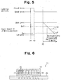
- the microcomputer 23 actuates the driver circuit 24 according to input signals V1 and V2. In more detail, the microcomputer 23 actuates the driver circuit 24 to rotate the motor M clockwise when the potential level at the down terminal 21 is less than or equal to an actuation threshold Von. The microcomputer 23 does not actuate the driver circuit 24 when the potential level at the down terminal 21 is greater than or equal to a non-actuation threshold Voff (non-actuation threshold Voff > actuation threshold Von: see Fig. 5). In the same manner, the microcomputer 23 actuates the driver circuit 24 to rotate the motor M counterclockwise when the potential level at the up terminal 22 is less than or equal to the actuation threshold Von.
- the microcomputer 23 does not actuate the driver circuit 24 when the potential level at the up terminal 22 is greater than or equal to the non-actuation threshold Voff. In this way, the microcomputer 23 executes active-low control over the motor M according to the level of the input signals V1 and V2.
- the connector 13 mounted on the board 25 is a right angle connector. Angle portions 26 of the terminals of the connector 13 are exposed on the board 25. In the preferred embodiment, at least an angle portion 26a of the ground terminal 18, among the angle portions 26 of all the terminals, is covered by a terminal cover 27 as shown in Figs. 2 and 3. As one example, the terminal cover 27 is made of resin (insulating member), and is integrally formed with the connector 13 by insert molding.
- Fig. 4 is a diagram showing the arrangement of the terminals of the connector 13 (as viewed in the direction of arrow A in Fig. 3).
- the up terminal 19 is arranged in the upper-row terminal group, and the down terminal 17 is arranged in the lower-row terminal group.
- the down terminal 17 is surrounded by battery terminals 20 (high-level terminals) arranged on both sides of, and above, the down terminal 17.
- the up terminal 19 is surrounded by battery terminals 20 arranged on both sides of, and under, the up terminal 19.
- the ground terminal 18 is arranged in a corner of the connector 13. The distance between the down terminal 17 and the ground terminal 18 is longer than the distance between the down terminal 17 and the battery terminals 20.
- the following describes a case in which the vehicle having the power window apparatus 1 with the above-described structure is, for example, submerged in water and water enters between the connector 13 and the board 25, with reference to Figs. 1 and 5.
- the lowering switch 15 and the raising switch 16 have the same structure, with the only difference being in the control executed by the microcomputer 23 (to raise or lower the window glass).
- the input signal V1 of the microcomputer 23 is normally held at a high-level. As shown in Fig. 5, when the lowering switch 15 is closed by operating the operation switch 10 at the timing indicated by point P1, the input signal V1 shifts to a low-level. The microcomputer 23 actuates the motor M according to the low-level input signal V1. When the lowering switch 15 is then opened by stopping the operation of the operation switch 10 at the timing indicated by point P2, the input signal V1 returns to the high-level. The microcomputer 23 stops the motor M according to the high-level input signal V1.
- a leakage current flows between an input terminal for an input signal and a ground terminal at the time of water entry.
- the level of the input signal V1 lowers as indicated by the dash-dot line X or the dash-dot-dot line Y in Fig. 5.
- the microcomputer 23 cannot recognize an opened or closed state of the lowering switch 15.
- the microcomputer 23 When the level of the input signal V1 is below the actuation threshold Von as indicated by the dash-dot-dot line Y, the microcomputer 23 incorrectly recognizes that the lowering switch 15 is in a closed state although the lowering switch 15 is actually in an opened state.
- the microcomputer 23 is provided with a low-level (the same level as when water does not enter into the terminals of the connector 13) input signal V1 via the down terminal 21.
- the microcomputer 23 determines that the lowering switch 15 is in a closed state based on the low-level input signal V1.
- the microcomputer 23 actuates the motor M to lower the window glass.
- the power window apparatus 1 of the preferred embodiment has the advantages described below.
- the down terminal 17 is surrounded by the battery terminals 20 arranged on both sides of, and under, the down terminal 17.
- the arrangement of the down terminal 17 and the battery terminals 20 should not be limited to such arrangement.
- the down terminal 17 may be arranged in a corner of the terminal group, that is, in a corner of the connector 13, and the battery terminals 20 may be arranged to surround this down terminal 17. This arrangement reduces the number of battery terminals 20 required to surround the down terminal 17.
- the number of battery terminals 20 included in the connector 13 may be increased. With a larger number of battery terminals 20, a leakage current is further unlikely to flow between the down terminal 17 and the battery terminals 20.
- the up terminal 19 may be arranged in a corner of the terminal group, and the BATTETY terminals 20 may be arranged to surround this up terminal 19.
- the battery terminal 20 having a larger surface area than the down terminal 17, or than the up terminal 19 may be arranged in the vicinity of the down terminal 17 and the up terminal 19. With the battery terminal 20 having such a larger surface area, a leakage current is further unlikely to flow between the down terminal 17 and the battery terminal 20, and between the up terminal 19 and the battery terminal 20.
- the terminal cover 27 is formed integrally with the connector 13 by, for example, performing insert molding. However, the terminal cover 27 may not be formed when the connector 13 is formed. For example, the terminal cover 27 may be formed by covering the angle portion 26a of the ground terminal 18 with potting resin (e.g., epoxy resin) after the connector 13 is mounted on the board 25.
- potting resin e.g., epoxy resin
- the angle portion 26a of the ground terminal 18 is covered by the terminal cover 27.
- the angle portion 26a of the ground terminal 18 may not be covered by the terminal cover 27.
- the battery terminals 20 are arranged between the down terminal 17 and the ground terminal 18, and between the up terminal 19 and the ground terminal 18, in a manner that the battery terminals 20 are away from the ground terminal 18.
- a potential substantially the same as the potential of the power supply Vo is generated around the battery terminals 20 when water enters into the angle portions 26 of the connector 13. The potential generated in this way inhibits a leakage current from flowing between the down terminal 17 and the ground terminal 18, and between the up terminal 19 and the ground terminal 18.
- the input signals V1 and V2 of the down terminal 17 and the up terminal 19 are likely to be maintained at a high-level. This structure prevents the microcomputer 23 from incorrectly recognizing that the lowering switch 15 or the raising switch 16 is in a closed state even when the power window apparatus 1 is submerged in water.
- the angle portion 26a of the ground terminal 18 may not be covered by the terminal cover 27, but the angle portion of the down terminal 17 and the angle portion of the up terminal 19 may be covered by the terminal covers 27. Further, the angle portion 26a of the ground terminal 18, the angle portion of the down terminal 17, and the angle portion of the up terminal 19 may be covered by the terminal covers 27.
- the connector 13 includes the battery terminals 20. However, the connector 13 may not include the battery terminals 20. Even when the connector 13 does not include the battery terminals 20, a leakage current does not flow between the down terminal 17 and the ground terminal 18, and between the up terminal 19 and the ground terminal 18 as long as the angle portion 26a of the ground terminal 18 is covered by the terminal cover 27.
- the switch unit 11 includes one connector 13.
- the switch unit 11 may include two connectors, namely, a first connector including the ground terminal 18, and a second connector including the down terminal 17, the up terminal 19, and the battery terminals 20. This structure ensures that the input signals V1 and V2 are maintained at a high-level even when the power window apparatus 1 is submerged in water.
Landscapes
- Business, Economics & Management (AREA)
- Engineering & Computer Science (AREA)
- Educational Administration (AREA)
- Educational Technology (AREA)
- Power-Operated Mechanisms For Wings (AREA)
- Window Of Vehicle (AREA)
Abstract
Description
Claims (19)
- A power window apparatus (1) for moving a window glass of a vehicle by driving an actuator, the power window apparatus comprising a switch (10) operated to cause the window glass to move, a control unit (23) for controlling the actuator, and a connector (13) having a connecting terminal (17, 19) connecting the switch and the control unit, wherein the connector has a ground terminal (18) used to connect the switch to ground, the switch connects the connecting terminal and the ground terminal to each other and generates a switch signal having a ground level at the connecting terminal when the switch is operated, and the control unit drives the actuator in response to the switch signal having the ground level; the power window apparatus characterized by
an inhibiting means (20, 27), arranged in the connector, for inhibiting leakage current from flowing between the connecting terminal and the ground terminal when the connector is submerged in water. - The power window apparatus according to claim 1, characterized in that the inhibiting means includes a terminal cover that covers at least one of the connecting terminal and the ground terminal and that is made from an insulative material.
- The power window apparatus according to claim 2, characterized in that the terminal cover is made of potting resin.
- The power window apparatus according to claim 2, characterized in that the connector and the terminal cover are made of resin and are integrally formed.
- The power window apparatus according to any one of claims 1 to 4, characterized in that the connecting terminal is provided with a signal having a power supply voltage when the switch is not operated, and the inhibiting means includes a power supply terminal that is arranged between the connecting terminal and the ground terminal and set at the power supply voltage.
- The power window apparatus according to claim 5, characterized in that the power supply terminal and the connecting terminal each have a surface area, with the surface area of the power supply terminal being larger than the surface area of the connecting terminal.
- The power window apparatus according to claim 5, characterized in that the power supply terminal is one of a plurality of power supply terminals surrounding the connecting terminal.
- The power window apparatus according to claim 7, characterized in that the plurality of power supply terminals are arranged on both sides of, and over, the connecting terminal or on both sides of, and under, the connecting terminal.
- The power window apparatus according to any one of claims 5 to 8, characterized in that a distance between the connecting terminal and the ground terminal is longer than a distance between the connecting terminal and the power supply terminal.
- The power window apparatus according to claim 9, characterized in that the connector has a first corner, and a second corner separated from the first corner, and the ground terminal is arranged in the first corner and the connecting terminal is arranged in the second corner.
- A power window apparatus (1) for moving a window glass of a vehicle by driving an actuator, wherein the power window apparatus is connected to a power supply, the power window apparatus comprising a switch (10) operated for generating a switch signal to cause the window glass to move, a control unit (23) for controlling the actuator, wherein the control unit includes an input terminal that is provided with the switch signal, a resistor (R1, R2) connected between the power supply and the input terminal of the control unit, and a connector (13) having a connecting terminal (17, 19) connecting the switch and the input terminal of the control unit, wherein the connector has a ground terminal (18) used to connect the switch to ground, the switch connects the connecting terminal and the ground terminal to each other and generates a switch signal having a ground level at the connecting terminal when the switch is operated, and the control unit drives the actuator in response to the switch signal having the ground level, characterized in that
the connector includes a power supply terminal (20) connected to the power supply and arranged between the connecting terminal and the ground terminal. - The power window apparatus according to claim 11, characterized in that the connector includes a terminal cover (27) that covers the ground terminal and is made from an insulative material.
- The power window apparatus according to claim 12, characterized in that the terminal cover is made of potting resin.
- The power window apparatus according to claim 12, characterized in that the connector and the terminal cover are made of resin and are integrally formed.
- The power window apparatus according to any one of claims 11 to 14, characterized in that the power supply terminal and the connecting terminal each have a surface area, with the surface area of the power supply terminal being larger than the surface area of the connecting terminal.
- The power window apparatus according to any one of claims 11 to 14, characterized in that the power supply terminal is one of a plurality of power supply terminals surrounding the connecting terminal.
- The power window apparatus according to claim 16, characterized in that the plurality of power supply terminals are arranged on both sides of, and over, the connecting terminal or on both sides of, and under, the connecting terminal.
- The power window apparatus according to any one of claims 11 to 17, characterized in that a distance between the connecting terminal and the ground terminal is longer than a distance between the connecting terminal and the power supply terminal.
- The power window apparatus according to claim 18, characterized in that the connector has a first corner, and a second corner separated from the first corner, and the ground terminal is arranged in the first corner and the connecting terminal is arranged in the second corner.
Applications Claiming Priority (2)
| Application Number | Priority Date | Filing Date | Title |
|---|---|---|---|
| JP2003121855 | 2003-04-25 | ||
| JP2003121855A JP4047757B2 (en) | 2003-04-25 | 2003-04-25 | Power window device |
Publications (3)
| Publication Number | Publication Date |
|---|---|
| EP1482386A2 true EP1482386A2 (en) | 2004-12-01 |
| EP1482386A3 EP1482386A3 (en) | 2010-03-17 |
| EP1482386B1 EP1482386B1 (en) | 2013-06-19 |
Family
ID=33128167
Family Applications (1)
| Application Number | Title | Priority Date | Filing Date |
|---|---|---|---|
| EP04252312.6A Expired - Lifetime EP1482386B1 (en) | 2003-04-25 | 2004-04-20 | Power window apparatus |
Country Status (5)
| Country | Link |
|---|---|
| US (1) | US6917170B2 (en) |
| EP (1) | EP1482386B1 (en) |
| JP (1) | JP4047757B2 (en) |
| KR (1) | KR100960347B1 (en) |
| CN (1) | CN100337007C (en) |
Cited By (1)
| Publication number | Priority date | Publication date | Assignee | Title |
|---|---|---|---|---|
| WO2010086123A1 (en) * | 2009-01-29 | 2010-08-05 | Brose Fahrzeugteile Gmbh & Co. Kommanditgesellschaft, Hallstadt | Controller for a window winder drive |
Families Citing this family (6)
| Publication number | Priority date | Publication date | Assignee | Title |
|---|---|---|---|---|
| JP4741969B2 (en) * | 2006-03-31 | 2011-08-10 | 日立オートモティブシステムズ株式会社 | Electrical and electronic module for automobile and method for mounting the same |
| JP2010283976A (en) * | 2009-06-04 | 2010-12-16 | Omron Automotive Electronics Co Ltd | Motor drive device |
| KR101197414B1 (en) * | 2012-07-20 | 2012-11-05 | (주)디에이치코프 | Apparatus for protecting an electric leakage when filled with water |
| JP5936269B2 (en) * | 2012-09-12 | 2016-06-22 | オムロンオートモーティブエレクトロニクス株式会社 | Vehicle window opening and closing control device |
| JP6101364B2 (en) * | 2013-01-09 | 2017-03-22 | ビジョン テック.インコーポレイテッド | Electrode structure having an electric shock prevention function |
| JP6969524B2 (en) * | 2018-08-30 | 2021-11-24 | 株式会社デンソー | Power window controller |
Family Cites Families (16)
| Publication number | Priority date | Publication date | Assignee | Title |
|---|---|---|---|---|
| US4575662A (en) * | 1984-11-26 | 1986-03-11 | General Motors Corporation | Vehicle power window control circuit |
| JPH0334813Y2 (en) * | 1985-05-07 | 1991-07-24 | ||
| JP3461432B2 (en) * | 1997-07-01 | 2003-10-27 | アルプス電気株式会社 | Power window device |
| JP3662718B2 (en) * | 1997-07-01 | 2005-06-22 | アスモ株式会社 | Power window equipment |
| EP0921256B1 (en) * | 1997-12-05 | 2004-03-17 | Alps Electric Co., Ltd. | Waterproof power window device |
| JP3479737B2 (en) * | 1998-04-09 | 2003-12-15 | 東洋電装株式会社 | Power window device |
| JP4226134B2 (en) * | 1999-03-15 | 2009-02-18 | 株式会社東海理化電機製作所 | Power window switch circuit |
| JP4399056B2 (en) * | 1999-05-13 | 2010-01-13 | 株式会社ミツバ | Window opening and closing device |
| JP3863326B2 (en) * | 1999-09-14 | 2006-12-27 | 株式会社東海理化電機製作所 | Leak sensor and insulating substrate |
| JP2001098844A (en) * | 1999-10-01 | 2001-04-10 | Yazaki Corp | Power window controller for automobile |
| US6404155B1 (en) * | 1999-11-12 | 2002-06-11 | Taiko Device, Ltd. | DC motor drive circuit |
| JP2001216033A (en) * | 2000-02-02 | 2001-08-10 | Yazaki Corp | Power supply control device and power supply control method |
| JP2002013964A (en) | 2000-04-26 | 2002-01-18 | Tokai Rika Co Ltd | Insulated board provided with water immersion sensor |
| JP3696052B2 (en) * | 2000-05-30 | 2005-09-14 | アルプス電気株式会社 | Water resistant power window device |
| DE10217831A1 (en) * | 2002-04-16 | 2003-11-06 | Sai Automotive Sal Gmbh | Vehicle door and method for its manufacture |
| JP2004034807A (en) * | 2002-07-02 | 2004-02-05 | Omron Corp | Opening / closing body control device |
-
2003
- 2003-04-25 JP JP2003121855A patent/JP4047757B2/en not_active Expired - Fee Related
-
2004
- 2004-04-20 EP EP04252312.6A patent/EP1482386B1/en not_active Expired - Lifetime
- 2004-04-22 US US10/829,500 patent/US6917170B2/en not_active Expired - Lifetime
- 2004-04-22 CN CNB2004100353724A patent/CN100337007C/en not_active Expired - Fee Related
- 2004-04-22 KR KR1020040027712A patent/KR100960347B1/en not_active Expired - Fee Related
Cited By (1)
| Publication number | Priority date | Publication date | Assignee | Title |
|---|---|---|---|---|
| WO2010086123A1 (en) * | 2009-01-29 | 2010-08-05 | Brose Fahrzeugteile Gmbh & Co. Kommanditgesellschaft, Hallstadt | Controller for a window winder drive |
Also Published As
| Publication number | Publication date |
|---|---|
| EP1482386A3 (en) | 2010-03-17 |
| KR100960347B1 (en) | 2010-05-28 |
| US6917170B2 (en) | 2005-07-12 |
| KR20040092453A (en) | 2004-11-03 |
| JP4047757B2 (en) | 2008-02-13 |
| EP1482386B1 (en) | 2013-06-19 |
| US20040212339A1 (en) | 2004-10-28 |
| CN1550635A (en) | 2004-12-01 |
| CN100337007C (en) | 2007-09-12 |
| JP2004322904A (en) | 2004-11-18 |
Similar Documents
| Publication | Publication Date | Title |
|---|---|---|
| EP0831012B1 (en) | Motor-assisted power steering apparatus | |
| US6201363B1 (en) | Power window apparatus | |
| US6917170B2 (en) | Power window apparatus | |
| US6956303B1 (en) | Electronic control device for controlling electric units of motor vehicle doors which have different equipment | |
| EP0739778A2 (en) | Power window circuit board overcurrent protection | |
| JPH1122300A (en) | Power window device | |
| US6724164B2 (en) | Opening-and-closing member control device | |
| US6965207B2 (en) | Power window apparatus | |
| US6975084B2 (en) | Power window controller | |
| US8314584B2 (en) | Motor arrangement with an electronic isolating relay module | |
| US20230062450A1 (en) | Drive unit with a control device | |
| EP0462171B1 (en) | A manually controlled key device | |
| US6927962B2 (en) | Submergence-responsive switching member driving circuit | |
| JP4285143B2 (en) | Vehicle switch | |
| CN115250588B (en) | Electronic Control Devices | |
| JP2001118465A (en) | Drive | |
| JP2002013964A (en) | Insulated board provided with water immersion sensor | |
| US20060006823A1 (en) | Method to control electric windows of automobiles by an activating button with two wires | |
| JP6086386B2 (en) | Power window device | |
| JPH08189253A (en) | Power window equipment | |
| JP3461437B2 (en) | Waterproof power window device | |
| JP3284033B2 (en) | Power window and door locking / unlocking control device | |
| WO2024176747A1 (en) | Connector and in-vehicle control system | |
| JP2002274169A (en) | Power window device with water immersion sensor | |
| JP2005065442A (en) | Drive device |
Legal Events
| Date | Code | Title | Description |
|---|---|---|---|
| PUAI | Public reference made under article 153(3) epc to a published international application that has entered the european phase |
Free format text: ORIGINAL CODE: 0009012 |
|
| AK | Designated contracting states |
Kind code of ref document: A2 Designated state(s): AT BE BG CH CY CZ DE DK EE ES FI FR GB GR HU IE IT LI LU MC NL PL PT RO SE SI SK TR |
|
| AX | Request for extension of the european patent |
Extension state: AL HR LT LV MK |
|
| PUAL | Search report despatched |
Free format text: ORIGINAL CODE: 0009013 |
|
| AK | Designated contracting states |
Kind code of ref document: A3 Designated state(s): AT BE BG CH CY CZ DE DK EE ES FI FR GB GR HU IE IT LI LU MC NL PL PT RO SE SI SK TR |
|
| AX | Request for extension of the european patent |
Extension state: AL HR LT LV MK |
|
| RIC1 | Information provided on ipc code assigned before grant |
Ipc: E05F 15/16 20060101ALI20100209BHEP Ipc: G05B 9/02 20060101AFI20041004BHEP Ipc: E05F 15/20 20060101ALI20100209BHEP |
|
| 17P | Request for examination filed |
Effective date: 20100423 |
|
| AKX | Designation fees paid |
Designated state(s): DE FR GB |
|
| 17Q | First examination report despatched |
Effective date: 20110405 |
|
| GRAP | Despatch of communication of intention to grant a patent |
Free format text: ORIGINAL CODE: EPIDOSNIGR1 |
|
| RIC1 | Information provided on ipc code assigned before grant |
Ipc: H01R 13/52 20060101ALI20130308BHEP Ipc: G05B 9/02 20060101AFI20130308BHEP Ipc: E05F 15/20 20060101ALI20130308BHEP Ipc: E05F 15/16 20060101ALI20130308BHEP |
|
| INTG | Intention to grant announced |
Effective date: 20130402 |
|
| GRAS | Grant fee paid |
Free format text: ORIGINAL CODE: EPIDOSNIGR3 |
|
| GRAA | (expected) grant |
Free format text: ORIGINAL CODE: 0009210 |
|
| RIN1 | Information on inventor provided before grant (corrected) |
Inventor name: TERAKAWA, KATSUTOSHI C/O K.K. TOKAI RIKA DENKI S. Inventor name: IGAWA, TOMOHIRO C/O K.K. TOKAI RIKA DENKI S. Inventor name: SUGIMOTO, SATOSHI C/O K.K. TOKAI RIKA DENKI S. |
|
| AK | Designated contracting states |
Kind code of ref document: B1 Designated state(s): DE FR GB |
|
| REG | Reference to a national code |
Ref country code: GB Ref legal event code: FG4D |
|
| REG | Reference to a national code |
Ref country code: DE Ref legal event code: R096 Ref document number: 602004042453 Country of ref document: DE Effective date: 20130814 |
|
| PLBE | No opposition filed within time limit |
Free format text: ORIGINAL CODE: 0009261 |
|
| STAA | Information on the status of an ep patent application or granted ep patent |
Free format text: STATUS: NO OPPOSITION FILED WITHIN TIME LIMIT |
|
| 26N | No opposition filed |
Effective date: 20140320 |
|
| REG | Reference to a national code |
Ref country code: DE Ref legal event code: R097 Ref document number: 602004042453 Country of ref document: DE Effective date: 20140320 |
|
| REG | Reference to a national code |
Ref country code: FR Ref legal event code: PLFP Year of fee payment: 13 |
|
| REG | Reference to a national code |
Ref country code: FR Ref legal event code: PLFP Year of fee payment: 14 |
|
| REG | Reference to a national code |
Ref country code: FR Ref legal event code: PLFP Year of fee payment: 15 |
|
| REG | Reference to a national code |
Ref country code: DE Ref legal event code: R084 Ref document number: 602004042453 Country of ref document: DE |
|
| PGFP | Annual fee paid to national office [announced via postgrant information from national office to epo] |
Ref country code: FR Payment date: 20200312 Year of fee payment: 17 |
|
| PGFP | Annual fee paid to national office [announced via postgrant information from national office to epo] |
Ref country code: GB Payment date: 20200408 Year of fee payment: 17 |
|
| REG | Reference to a national code |
Ref country code: DE Ref legal event code: R082 Ref document number: 602004042453 Country of ref document: DE |
|
| PGFP | Annual fee paid to national office [announced via postgrant information from national office to epo] |
Ref country code: DE Payment date: 20210323 Year of fee payment: 18 |
|
| GBPC | Gb: european patent ceased through non-payment of renewal fee |
Effective date: 20210420 |
|
| PG25 | Lapsed in a contracting state [announced via postgrant information from national office to epo] |
Ref country code: GB Free format text: LAPSE BECAUSE OF NON-PAYMENT OF DUE FEES Effective date: 20210420 Ref country code: FR Free format text: LAPSE BECAUSE OF NON-PAYMENT OF DUE FEES Effective date: 20210430 |
|
| REG | Reference to a national code |
Ref country code: DE Ref legal event code: R119 Ref document number: 602004042453 Country of ref document: DE |
|
| PG25 | Lapsed in a contracting state [announced via postgrant information from national office to epo] |
Ref country code: DE Free format text: LAPSE BECAUSE OF NON-PAYMENT OF DUE FEES Effective date: 20221103 |