EP1482303A2 - Method of dynamically displaying a scattering vector of X-ray diffraction - Google Patents
Method of dynamically displaying a scattering vector of X-ray diffraction Download PDFInfo
- Publication number
- EP1482303A2 EP1482303A2 EP04012577A EP04012577A EP1482303A2 EP 1482303 A2 EP1482303 A2 EP 1482303A2 EP 04012577 A EP04012577 A EP 04012577A EP 04012577 A EP04012577 A EP 04012577A EP 1482303 A2 EP1482303 A2 EP 1482303A2
- Authority
- EP
- European Patent Office
- Prior art keywords
- ray diffraction
- scattering vector
- measurement
- point
- tracks
- Prior art date
- Legal status (The legal status is an assumption and is not a legal conclusion. Google has not performed a legal analysis and makes no representation as to the accuracy of the status listed.)
- Withdrawn
Links
Images



Classifications
-
- G—PHYSICS
- G01—MEASURING; TESTING
- G01N—INVESTIGATING OR ANALYSING MATERIALS BY DETERMINING THEIR CHEMICAL OR PHYSICAL PROPERTIES
- G01N23/00—Investigating or analysing materials by the use of wave or particle radiation, e.g. X-rays or neutrons, not covered by groups G01N3/00 – G01N17/00, G01N21/00 or G01N22/00
- G01N23/20—Investigating or analysing materials by the use of wave or particle radiation, e.g. X-rays or neutrons, not covered by groups G01N3/00 – G01N17/00, G01N21/00 or G01N22/00 by using diffraction of the radiation by the materials, e.g. for investigating crystal structure; by using scattering of the radiation by the materials, e.g. for investigating non-crystalline materials; by using reflection of the radiation by the materials
- G01N23/2055—Analysing diffraction patterns
Definitions
- the present invention relates to a method of dynamically displaying a motion of the tip location of a scattering vector of X-ray diffraction.
- the scattering vector of X-ray diffraction is a concept which has been introduced to explain theoretically the X-ray diffraction phenomenon.
- the scattering vector is helpful in understanding the X-ray diffraction phenomenon.
- the scattering vector is indeed useful in considering measuring conditions and in interpreting measured results in the actual X-ray diffraction measurement procedure.
- the scattering vector is a useful concept as described above, its direction and magnitude are invisible because the scattering,vector is an imaginary existence which is defined by the relative location among an X-ray source, a sample and an X-ray detector.
- a method according to the present invention comprises a step of displaying two-dimensionally or three-dimensionally a dynamic motion and tracks of the tip location of a scattering vector of X-ray diffraction under changing measuring conditions on a display screen which represents the reciprocal space of a sample crystal.
- This invention has an advantage that the tip location of the scattering vector can be seen dynamically and the X-ray diffraction phenomenon under changing measuring conditions can be readily understood, effecting easy consideration of the measuring conditions and easy evaluation of the measured results.
- the dynamic display method is usable for a dynamic simulation, in which (1) an operator enters measuring conditions into a measuring-condition setting device, (2) a control device acquires the measuring conditions, and (3) the control device puts the virtual scattering vector in motion on a display screen based on the measuring conditions acquired.
- the dynamic display method is for showing neither the movement of a visible X-ray detector nor a visible sample but the motion of the scattering vector in the reciprocal space dynamically, the scattering vector being invisible actually but representing importantly the nature of the X-ray diffraction phenomenon.
- the method of the present invention is therefore best suited for the study of measuring conditions.
- the dynamic display method is effective in showing the X-ray diffraction phenomenon visually for persons not familiar with the X-ray diffraction.
- the measuring-condition setting device can acquire the measuring conditions under which the measurement has been completed so as to dynamically display the scattering vector which has been used, helpful in understanding the measured results.
- the intensity information can be expressed by the color or width of the tracks on the display screen, for example.
- the X-ray diffraction principle suggests that when the tip location of the scattering vector coincides with any reciprocal lattice point, an X-ray diffraction phenomenon occurs at the crystal lattice plane corresponding to the reciprocal lattice point. Therefore, observing the superposition of the locations of the reciprocal lattice points on the tracks makes it possible to determine whether or not X-ray diffraction occurs on the tracks.
- Fig. 1 is a view for explaining the scattering vector H of X-ray diffraction, in which an X-ray 12 is incident on the surface of a sample 10, and a diffracted X-ray 14 goes out of the sample surface.
- An angle of the incident X-ray 12 to the surface of the sample 10 is referred to as an incident angle which is denoted by ⁇
- an angle of the diffracted X-ray 14 to the incident angle 12 is referred to as a diffraction angle which is denoted by 2 ⁇ .
- the incident X-ray 12 comes from an X-ray source 16, and the diffracted X-ray 14 is to be detected by an X-ray detector 18.
- An X-ray diffraction phenomenon will be explained with the use of the reciprocal space of the crystal which makes up the sample 10.
- a unit vector So is taken as extending in the direction of the incident X-ray 12
- another unit vector S is taken as extending in the direction of the diffracted X-ray 14.
- an incident X-ray vector is defined as S 0 / ⁇
- a diffracted X-ray vector is defined as S/ ⁇ where ⁇ is the wavelength of an X-ray
- vectorial subtraction of the incident X-ray vector from the diffracted X-ray vector becomes, as well known, the scattering vector H.
- the X-ray diffraction principle suggests that when the tip location of the scattering vector H coincides with any lattice point in the reciprocal space, X-ray diffraction occurs at the real lattice plane 20, which is a crystal lattice plane in the real space, corresponding to the reciprocal lattice point.
- the scattering vector H has the property that the direction is perpendicular to the real lattice plane 20 and the magnitude is equal to the inverse number of the lattice spacing of the real lattice plane 20.
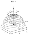
- Fig. 2 shows one example of a screen image in which the dynamic display method according to the invention is applied to the pole figure measurement.
- the screen image indicates the reciprocal space of the crystal which makes up the sample 10.
- An orthogonal coordinate system including qx, qy and qz in the reciprocal space defines a three-dimensional space. If the sample crystal is tetragonal or cubic, the reciprocal space becomes a three-dimensional orthogonal coordinate system, in which a qz-axis is defined as extending in the normal direction of the sample surface and a qx-axis and a qy-axis are defined as being on the sample surface.
- measuring conditions are selected to become a combination of (1) a setting condition in which the X-ray diffraction optical system, which includes the incident X-ray 12 and the diffracted X-ray 14, is inclined to a direction of an angle ⁇ shown in Fig. 2 on the basis of the sample 10 and (2) another setting condition in which the X-ray diffraction optical system is rotated around the normal of the sample 10, which coincides with the qz-axis, by an angle ⁇ In Fig. 2, an angle of the diffracted X-ray 14 to the incident X-ray 12, i.e., a diffraction angle 2 ⁇ , is set to 60 degrees.
- the angle ⁇ is selected to range from zero degree, i.e., the condition in which the scattering vector H coincides with the normal of the sample surface, to 30 degrees at ten-degree intervals.
- the angle ⁇ is selected to range from zero to 360 degrees at five-degree intervals.
- the motion tracks of the tip location of the scattering vector are represented as heavy full lines in Fig. 2 under the measuring conditions made of combinations of ⁇ and ⁇ .
- Fig. 6 shows an enlarged view of a part of the screen image shown in Fig. 2.
- the tip of the scattering vector H has a place at a point A at the start of the measurement.
- X-ray diffraction measurement is carried out initially at this point, i.e., the intensity of a diffracted X-ray is detected.
- the X-ray diffraction optical system is inclined on the basis of the sample so that the angle ⁇ becomes 10 degrees and the tip of the scattering vector H has a place at a point B, noting however that in the actual apparatus the sample may be inclined while the X-ray diffraction optical system may be held stationary.
- the angle ⁇ is changed stepwise at five-degree intervals from zero to 360 degrees, so that X-ray diffraction measurement is carried out for seventy-two values of ⁇ .
- the scattering vector H rotates around the qz-axis with one revolution and returns to the point B with the angle ⁇ being held 10 degrees.
- the angle ⁇ is changed to 20 degrees and the angle ⁇ is changed at five-degree intervals so as to carry out X-ray diffraction measurement.
- Fig. 6 shows the tracks of the tip location of the scattering vector H after completion of the measurement under the condition of the angle ⁇ ranging from zero to 30 degrees.
- the tip location of the scattering vector H starts from the point A, and moves to the point B, and rotates around the qz-axis with one revolution back to the point B, and moves to a point C, and rotates around the qz-axis with one revolution back to the point C, and moves to a point D, and rotates around the qz-axis with one revolution back to the point D to complete the measurement.
- the motion of the tip location of the scattering vector H can be displayed on a screen in real time during the pole figure measurement, and the tracks of the motion remains displayed on the screen. Accordingly, an operator of the pole figure measurement can understand in real time where the tip location of the scattering vector H is at the moment.
- the tracks can be displayed on the screen even if the X-ray diffraction measurement is not carried out. That is, the operator can enter the measuring conditions made of many combinations of ⁇ and ⁇ into the measuring-condition setting device, so that the motion of the tip location of the scattering vector and the tracks of the motion can be dynamically displayed without X-ray diffraction measurement.
- FIG. 3 shows an example of a picture on a screen in which the dynamic display method according to the invention is applied to the reciprocal-space mapping measurement.
- the picture shows dynamically the motion of the tip location of the scattering vector and the motion tracks in the case of a series of operations of (1) reciprocal-space mapping measurement within a plane perpendicular to the sample surface, referred to hereinafter as out-of-plane reciprocal-space mapping, and (2) reciprocal-space mapping measurement with a plane including the sample surface, referred to hereinafter as in-plane reciprocal-space mapping.
- the out-of-plane reciprocal-space mapping measurement is carried out under the measuring conditions described below.
- the center of the mapping is 60 degrees in 2 ⁇ and 20 degrees in ⁇ , the 2 ⁇ / ⁇ is selected to range from 50 to 70 degrees at two-degree intervals, and the ⁇ is selected to range from minus 10 to plus 10 degrees at two-degree intervals, noting that the definition of 2 ⁇ and ⁇ is shown in Fig. 1.
- the in-plane reciprocal-space mapping measurement is carried out under the conditions that the center of the mapping is 60 degrees in 2 ⁇ and 20 degrees in ⁇ , the 2 ⁇ / ⁇ is selected to range from 50 to 70 degrees at two-degree intervals, and the ⁇ is selected to range from minus 10 to plus 10 degrees at two-degree intervals, noting that the angle ⁇ is an angle of in-plane rotation of the sample and the angle 2 ⁇ is a diffraction angle corresponding to 2 ⁇ in the out-of-plane diffraction.
- the tip location of the scattering vector H starts from a point A which is minus 10 degrees in ⁇ and 50 degrees in 2 ⁇ / ⁇ ). The tip location then moves from this point to a point B, which is the same as the point A in ⁇ and 70 degrees in 2 ⁇ / ⁇ , such a movement being referred to as a 2 ⁇ / ⁇ scan. Eleven operations of X-ray diffraction measurement are carried out at two-degree intervals in 2 ⁇ / ⁇ . During the X-ray measurement, an operator looking at the screen will observe that the tip location of the scattering vector H is moving from the point A to the point B, the direction of the scattering vector H being unchanged.
- the tip location of the scattering vector H moves from the point B to a point C, i.e., ⁇ is set at minus eight degrees and 2 ⁇ / ⁇ is returned to 50 degrees.
- the 2 ⁇ / ⁇ scan is carried out again from the point C so as to prosecute additional eleven operations of X-ray diffraction measurement similarly.
- Such procedures are carried out for eleven values of ⁇ ranging from minus 10 to plus 10 degrees.
- the final location of the out-of-plane reciprocal-space mapping measurement has a place of a point D.
- the frequency of the measurement operations runs up eleven times eleven being a hundred and twenty one.
- the procedure moves to the in-plane reciprocal-space mapping measurement.
- the tip location of the scattering vector H at the point D now moves drastically to a point E which is on the sample surface, the point E being minus 10 degrees in ⁇ and 50 degrees in 2 ⁇ / ⁇ .
- the tip location then moves from this point to a point F, which is the same as the point E in ⁇ and 70 degrees in 2 ⁇ / ⁇ , so as to carry out eleven measurement operations of X-ray diffraction at two-degree intervals in 2 ⁇ / ⁇ , such a movement being referred to as a 2 ⁇ / ⁇ scan.
- an operator looking at the screen will observe that the tip location of the scattering vector H is moving from the point E to the point F with the direction of the scattering vector H unchanged.
- the tip location of the scattering vector H jumps from the point F to a point G, i.e., ⁇ is changed to minus eight degrees and 2 ⁇ / ⁇ is returned to 50 degrees.
- the 2 ⁇ / ⁇ scan is carried out again from the point G so as to prosecute additional eleven operations of X-ray diffraction measurement similarly.
- Such procedures are carried out with eleven values of ⁇ ranging from minus 10 degrees to plus 10 degrees.
- the final location of the in-plane reciprocal-space mapping measurement has a place of a point J.
- the frequency of the measurement operations in the in-plane reciprocal-space mapping also runs up eleven times eleven being a hundred and twenty one.
- the tip location of the scattering vector is to move within the qy-qz plane only, it being sufficient to display only a two-dimensional reciprocal space for the tack indication of the tip location of the scattering vector.
- the tip location of the scattering vector is to move within the qx-qy plane only, it being sufficient to display only a two-dimensional reciprocal space alike.
- Fig. 4 shows an example of a picture on a screen in which the dynamic display method according to the invention is applied to mesh measurement.
- the picture shows dynamically the motion of the tip location of the scattering vector and the motion tracks in the case of a series of operations for (1) mesh measurement within a plane perpendicular to the sample surface, referred to hereinafter as out-of-plane mesh measurement, and (2) mesh measurement within a plane including the sample surface, referred to hereinafter as in-plane mesh measurement.
- the out-of-plane mesh measurement is carried out under the measuring conditions described below.
- the center of the mesh measurement is located at zero in qy and 0.8 in qz.
- ⁇ qy is selected to range from minus 0.1 to plus 0.1 at 0.02 intervals on the basis of the center position mentioned above, and ⁇ qz is selected to range from minus 0.1 to plus 0.1 at 0.02 intervals similarly, noting that the measures of qy and qz are the inverse number of angstrom and also the measure of qx is the same.
- the in-plane mesh measurement is carried out under the conditions in which the center of the mesh measurement is located at zero in qy and 0.8 in qx.
- the value of ⁇ qx is selected to range from minus 0.1 to plus 0.1 at 0.02 intervals and ⁇ qy is selected to range from minus 0.1 to plus 0.1 at 0.02 intervals similarly.
- the tip location of the scattering vector H starts from a point A which is minus 0.1 in ⁇ qy and minus 0.1 in ⁇ qz.
- the tip location then moves from this point to a point B, which is the same as the point A in ⁇ qz and plus 0.1 in ⁇ qy, so as to carry out eleven measurement operations of X-ray diffraction at 0.02 intervals in ⁇ qy, such a movement being referred to hereinafter as a qy scan.
- a qy scan an operator looking at the screen will observe that the tip location of the scattering vector H is moving horizontally rightward from the point A to the point B.
- the tip location of the scattering vector H jumps from the point B to a point C, i.e., ⁇ qz is changed to minus 0.08 and ⁇ qy is returned to minus 0.1.
- the qy scan is carried out again from the point C so as to prosecute additional eleven operations of X-ray diffraction measurement similarly. Such procedures are carried out for eleven values of ⁇ qz ranging from minus 0.1 to plus 0.1.
- the final location of the out-of-plane mesh measurement has a place of a point D.
- the frequency of the measurement operations runs up eleven times eleven being a hundred and twenty one.
- the procedure moves to the in-plane mesh measurement.
- the tip location of the scattering vector H at the point D now moves drastically to a point E which is on the sample surface, the point E being minus 0.01 in ⁇ qx and minus 0.01 in ⁇ qy.
- the tip location then moves from this point to a point F, which is the same as the point E in ⁇ qx and plus 0.1 in ⁇ qy, so as to carry out eleven measurement operations of X-ray diffraction at 0.02 intervals in ⁇ qy, such movement being referred to also as the qy scan.
- an operator looking at the screen will observe that the tip location of the scattering vector H is moving horizontally rightward from the point E to the point F within the sample surface.
- the tip location of the scattering vector H jumps from the point F to a point G, i.e., ⁇ qx is changed to minus 0.08 and ⁇ qy is returned to minus 0.1.
- the qy scan is carried out again from the point G so as to prosecute additional eleven operations of X-ray diffraction measurement similarly. Such procedures are carried out for eleven values of ⁇ qx ranging from minus 0.1 to plus 0.1.
- the final location of the in-plane mesh measurement has a place of a point J.
- the frequency of the measurement operations for the in-plane mesh measurement also runs up eleven times eleven being a hundred and twenty one.
- Fig. 5 shows an example of a picture on a screen in which the dynamic display method according to the invention is applied to three-dimensional mesh measurement, which is carried out under the measuring conditions described below. All the values of qx, qy and qx are selected to range from 0.1 to 0.5 at 0.1 intervals so as to prosecute operations of the X-ray diffraction measurement, noting that the measures of qx, qy and qz are the inverse number of angstrom. The frequency of the measurement operations runs up five times five times five being a hundred and twenty five.
- the tip location of the scattering vector H starts from a point A which is 0.1 in qx, 0.1 in qy and 0.1 in qz.
- the tip location then moves from this point to a point B, which is the same as the point A in qy and qz and 0.5 in qx, so as to carry out five operations of X-ray diffraction measurement at 0.1 intervals in qx, such a movement being referred to hereinafter as a qx scan.
- the tip location of the scattering vector H jumps from the point B to a point C, i.e., qy is changed to 0.2 and qx is returned to 0.1, noting that qz remains as it is.
- the qx scan is carried out again from the point C so as to prosecute additional five operations of X-ray diffraction measurement similarly.
- Such procedures are carried out for five values of qy ranging from 0.1 to 0.5.
- the tip location of the scattering vector reaches at a point D on completion of twenty-five operations, five times five, with qz remaining unchanged.
- the tip location of the scattering vector H jumps from the point D to a point E, which is 0.1 higher in qz than the point A.
- Similar operations are carried for five values of qz ranging from 0.1 to 0.5.
- the final location has a place of a point F to complete the measurement, and the frequency of the measurement operations runs up a hundred and twenty five.
- the procedures of the X-ray diffraction measurement may be carried out with the continuous scan or the stepwise scan in scanning the measuring conditions for prosecuting the examples described above.
- the continuous scan is defined as to carry out each operation of the X-ray diffraction measurement during a continuous change in angle to be scanned.
- the stepwise scan is defined as to carry out each operation of the X-ray diffraction measurement at a temporarily stationary angle to be scanned.
- the obtained X-ray diffraction intensity should be taken as the data at the center position of the angle which changes during the measurement operation.
- the lattice points of the reciprocal lattice may be superimposed on a display of the motion and tracks of the tip location of the scattering vector in carrying out the present invention.
- Fig. 7 shows superposition of the reciprocal lattice over the dynamic picture shown in Fig. 2.
- the X-ray diffraction principle suggests that when the tip location of the scattering vector coincides with any lattice point in the reciprocal space, X-ray diffraction occurs at the real lattice plane corresponding to the reciprocal lattice point. An operator can perceive useful information from the superimposed picture shown in Fig.
- the tip location of the scattering vector is moving closer to one of the reciprocal lattice points or the tip location is just passing through one of the reciprocal lattice points.
- the superimposed picture is accordingly very helpful in understanding the status of the X-ray diffraction.
- lattice points 26 of the reciprocal space are expressed by intersections of many line segments 24 which passing through the lattice points 26, the expression is not to be considered limited to the intersections but the lattice points may be expressed by black spots or the like.
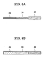
- Fig. 8A shows an example in which the track line segment has a width which changes according to the diffraction intensity data.
- the track is expressed by a line segment 28 having a width corresponding to one pixel of the display screen when the intensity of a diffracted X-ray is less than the predetermined minimum value, including zero.
- the width varies with the intensity such that a line segment 30 with a higher intensity has a width corresponding to two pixels, and a line segment 32 with a further higher intensity has a width corresponding to three pixels. It can be seen accordingly from the picture on a screen how the diffraction intensity varies along the tracks of the tip location of the scattering vector.
- Fig. 8B shows an example in which the track line segment has a color which changes according to the diffraction intensity data.
- the color varies with the intensity such that a line segment 34 has the first color, a line segment 36 has the second color and a line segment 38 has the third color.
- the color may be changed only in brightness with the same hue unchanged, i.e., the gray scale expression. Alternatively, the color may be changed in hue for a colorful expression.
Landscapes
- Chemical & Material Sciences (AREA)
- Crystallography & Structural Chemistry (AREA)
- Physics & Mathematics (AREA)
- Health & Medical Sciences (AREA)
- Life Sciences & Earth Sciences (AREA)
- Analytical Chemistry (AREA)
- Biochemistry (AREA)
- General Health & Medical Sciences (AREA)
- General Physics & Mathematics (AREA)
- Immunology (AREA)
- Pathology (AREA)
- Analysing Materials By The Use Of Radiation (AREA)
- Management, Administration, Business Operations System, And Electronic Commerce (AREA)
Abstract
Description
- 10
- sample
- 12
- incident X-ray
- 14
- diffracted X-ray
- 16
- X-ray source
- 18
- X-ray detector
- 20
- crystal lattice plane
- H
- scattering vector
Claims (7)
- A method of dynamically displaying a scattering vector of X-ray diffraction comprising a step of:displaying two-dimensionally or three-dimensionally a dynamic motion and tracks of a tip location of a scattering vector of X-ray diffraction under changing measuring conditions of X-ray diffraction on a display screen which represents a reciprocal space of a sample crystal.
- A method according to claim 1, wherein said dynamic motion and tracks is displayed during X-ray diffraction measurement.
- A method according to claim 1, wherein said displaying step includes:acquiring a change of measuring conditions from a measuring-condition setting device; anddisplaying said dynamic motion and tracks in accordance with said change of measuring conditions acquired.
- A method according to claim 1, wherein said tracks is displayed along with information about an X-ray diffraction intensity.
- A method according to claim 4, wherein said information is expressed in a color of said tracks.
- A method according to claim 4, wherein said information is expressed in a width of said tracks.
- A method according to claim 1, further comprising a step of superimposing locations of reciprocal lattice points on said tracks.
Applications Claiming Priority (2)
| Application Number | Priority Date | Filing Date | Title |
|---|---|---|---|
| JP2003153496A JP3697251B2 (en) | 2003-05-29 | 2003-05-29 | Dynamic display method of scattering vector of X-ray diffraction |
| JP2003153496 | 2003-05-29 |
Publications (2)
| Publication Number | Publication Date |
|---|---|
| EP1482303A2 true EP1482303A2 (en) | 2004-12-01 |
| EP1482303A3 EP1482303A3 (en) | 2005-12-21 |
Family
ID=33128291
Family Applications (1)
| Application Number | Title | Priority Date | Filing Date |
|---|---|---|---|
| EP04012577A Withdrawn EP1482303A3 (en) | 2003-05-29 | 2004-05-27 | Method of dynamically displaying a scattering vector of X-ray diffraction |
Country Status (3)
| Country | Link |
|---|---|
| US (1) | US7120227B2 (en) |
| EP (1) | EP1482303A3 (en) |
| JP (1) | JP3697251B2 (en) |
Families Citing this family (12)
| Publication number | Priority date | Publication date | Assignee | Title |
|---|---|---|---|---|
| JP4020400B2 (en) * | 2004-08-31 | 2007-12-12 | 株式会社リガク | X-ray diffractometer |
| US7492863B2 (en) * | 2006-08-02 | 2009-02-17 | Ge Security, Inc. | Method for developing an x-ray diffraction imaging system |
| US8243878B2 (en) * | 2010-01-07 | 2012-08-14 | Jordan Valley Semiconductors Ltd. | High-resolution X-ray diffraction measurement with enhanced sensitivity |
| US8687766B2 (en) | 2010-07-13 | 2014-04-01 | Jordan Valley Semiconductors Ltd. | Enhancing accuracy of fast high-resolution X-ray diffractometry |
| US8437450B2 (en) | 2010-12-02 | 2013-05-07 | Jordan Valley Semiconductors Ltd. | Fast measurement of X-ray diffraction from tilted layers |
| US8781070B2 (en) | 2011-08-11 | 2014-07-15 | Jordan Valley Semiconductors Ltd. | Detection of wafer-edge defects |
| JP5511020B2 (en) * | 2011-11-24 | 2014-06-04 | 株式会社リガク | X-ray analyzer |
| US9091628B2 (en) | 2012-12-21 | 2015-07-28 | L-3 Communications Security And Detection Systems, Inc. | 3D mapping with two orthogonal imaging views |
| US9726624B2 (en) | 2014-06-18 | 2017-08-08 | Bruker Jv Israel Ltd. | Using multiple sources/detectors for high-throughput X-ray topography measurement |
| JP6606706B2 (en) * | 2016-06-24 | 2019-11-20 | 株式会社リガク | Processing method, processing apparatus, and processing program |
| EP3561496B1 (en) * | 2018-04-24 | 2021-10-06 | Rigaku Corporation | Technique for processing x-ray diffraction data |
| CN118294484B (en) * | 2023-11-21 | 2025-04-25 | 张江国家实验室 | Grazing incidence small-angle X-ray scattering Bragg peak positioning method |
Family Cites Families (3)
| Publication number | Priority date | Publication date | Assignee | Title |
|---|---|---|---|---|
| US7337098B2 (en) * | 1998-05-18 | 2008-02-26 | Rigaku Corporation | Diffraction condition simulation device, diffraction measurement system, and crystal analysis system |
| JP3889183B2 (en) | 1998-05-18 | 2007-03-07 | 株式会社リガク | Diffraction condition simulation device, diffraction measurement system, and crystal analysis system |
| JP3561738B2 (en) * | 1998-06-02 | 2004-09-02 | 株式会社リガク | Method and apparatus for automatically selecting Bragg reflection and method and system for automatically determining crystal orientation |
-
2003
- 2003-05-29 JP JP2003153496A patent/JP3697251B2/en not_active Expired - Fee Related
-
2004
- 2004-05-25 US US10/854,562 patent/US7120227B2/en not_active Expired - Fee Related
- 2004-05-27 EP EP04012577A patent/EP1482303A3/en not_active Withdrawn
Also Published As
| Publication number | Publication date |
|---|---|
| US7120227B2 (en) | 2006-10-10 |
| JP2004354261A (en) | 2004-12-16 |
| US20050002488A1 (en) | 2005-01-06 |
| JP3697251B2 (en) | 2005-09-21 |
| EP1482303A3 (en) | 2005-12-21 |
Similar Documents
| Publication | Publication Date | Title |
|---|---|---|
| US7120227B2 (en) | Method of displaying dynamically scattering vector of X-ray diffraction | |
| Bhowmick et al. | Identification of full-field dynamic modes using continuous displacement response estimated from vibrating edge video | |
| US6078396A (en) | Non-contact deformation measurement | |
| US20060078085A1 (en) | Stereoscopic x-ray imaging apparatus for obtaining three dimensional coordinates | |
| Hall et al. | Discrete and continuum analysis of localised deformation in sand using X-ray μCT and volumetric digital image correlation | |
| KR100576228B1 (en) | A multiple view angle x-ray stereoscopic imaging method and system | |
| CA3016136C (en) | System and method for analyzing drill core samples | |
| EP1190211B1 (en) | Method for optically detecting the shape of objects | |
| KR20120062624A (en) | X-ray diffraction apparatus and x-ray diffraction measurement method | |
| US7696991B2 (en) | Method and apparatus for analyzing twinned crystal | |
| Patterson | Automated photoelastic analysis | |
| EP0969417A2 (en) | Method and apparatus for displaying three-dimensional image by use of tensor rendering | |
| US5600432A (en) | Method and apparatus for measurement of resolution of imaging systems | |
| EP0593210A2 (en) | Track width error inspector apparatus | |
| KR20180003889A (en) | Apparatus for biometic information | |
| CA2955391A1 (en) | Method and apparatus for measuring optical systems and surfaces with optical ray metrology | |
| Nicoletto et al. | Application of high magnification digital image correlation technique to micromechanical strain analysis | |
| JP3449810B2 (en) | Blood flow information display method | |
| Boochs et al. | Potential of high-precision measuring techniques for the monitoring of surfaces from heritage objects | |
| JPH10239255A (en) | Crystal grain 3D display method | |
| JPH0534131A (en) | Image processing method and image processing apparatus | |
| GB2275773A (en) | Video thermography for detecting subsurface flaws | |
| JPH04175648A (en) | Fluorescent x-ray analyzing device | |
| US12555250B1 (en) | Visual renderings of modal analysis test frequencies from mathematically-modified video test recordings | |
| Saveljev et al. | Moiré effect without grid |
Legal Events
| Date | Code | Title | Description |
|---|---|---|---|
| PUAI | Public reference made under article 153(3) epc to a published international application that has entered the european phase |
Free format text: ORIGINAL CODE: 0009012 |
|
| AK | Designated contracting states |
Kind code of ref document: A2 Designated state(s): AT BE BG CH CY CZ DE DK EE ES FI FR GB GR HU IE IT LI LU MC NL PL PT RO SE SI SK TR |
|
| AX | Request for extension of the european patent |
Extension state: AL HR LT LV MK |
|
| PUAL | Search report despatched |
Free format text: ORIGINAL CODE: 0009013 |
|
| AK | Designated contracting states |
Kind code of ref document: A3 Designated state(s): AT BE BG CH CY CZ DE DK EE ES FI FR GB GR HU IE IT LI LU MC NL PL PT RO SE SI SK TR |
|
| AX | Request for extension of the european patent |
Extension state: AL HR LT LV MK |
|
| 17P | Request for examination filed |
Effective date: 20060328 |
|
| AKX | Designation fees paid |
Designated state(s): DE GB |
|
| 17Q | First examination report despatched |
Effective date: 20110826 |
|
| STAA | Information on the status of an ep patent application or granted ep patent |
Free format text: STATUS: THE APPLICATION IS DEEMED TO BE WITHDRAWN |
|
| 18D | Application deemed to be withdrawn |
Effective date: 20111201 |