EP1482299B1 - Test sensor and method for manufacturing the same - Google Patents
Test sensor and method for manufacturing the same Download PDFInfo
- Publication number
- EP1482299B1 EP1482299B1 EP04012423A EP04012423A EP1482299B1 EP 1482299 B1 EP1482299 B1 EP 1482299B1 EP 04012423 A EP04012423 A EP 04012423A EP 04012423 A EP04012423 A EP 04012423A EP 1482299 B1 EP1482299 B1 EP 1482299B1
- Authority
- EP
- European Patent Office
- Prior art keywords
- test
- membrane
- reagent
- test membrane
- carrier
- Prior art date
- Legal status (The legal status is an assumption and is not a legal conclusion. Google has not performed a legal analysis and makes no representation as to the accuracy of the status listed.)
- Expired - Lifetime
Links
Images




Classifications
-
- G—PHYSICS
- G01—MEASURING; TESTING
- G01N—INVESTIGATING OR ANALYSING MATERIALS BY DETERMINING THEIR CHEMICAL OR PHYSICAL PROPERTIES
- G01N33/00—Investigating or analysing materials by specific methods not covered by groups G01N1/00 - G01N31/00
- G01N33/48—Biological material, e.g. blood, urine; Haemocytometers
- G01N33/50—Chemical analysis of biological material, e.g. blood, urine; Testing involving biospecific ligand binding methods; Immunological testing
- G01N33/52—Use of compounds or compositions for colorimetric, spectrophotometric or fluorometric investigation, e.g. use of reagent paper and including single- and multilayer analytical elements
- G01N33/525—Multi-layer analytical elements
-
- A—HUMAN NECESSITIES
- A61—MEDICAL OR VETERINARY SCIENCE; HYGIENE
- A61B—DIAGNOSIS; SURGERY; IDENTIFICATION
- A61B5/00—Measuring for diagnostic purposes; Identification of persons
- A61B5/145—Measuring characteristics of blood in vivo, e.g. gas concentration or pH-value ; Measuring characteristics of body fluids or tissues, e.g. interstitial fluid or cerebral tissue
- A61B5/14532—Measuring characteristics of blood in vivo, e.g. gas concentration or pH-value ; Measuring characteristics of body fluids or tissues, e.g. interstitial fluid or cerebral tissue for measuring glucose, e.g. by tissue impedance measurement
-
- A—HUMAN NECESSITIES
- A61—MEDICAL OR VETERINARY SCIENCE; HYGIENE
- A61B—DIAGNOSIS; SURGERY; IDENTIFICATION
- A61B5/00—Measuring for diagnostic purposes; Identification of persons
- A61B5/145—Measuring characteristics of blood in vivo, e.g. gas concentration or pH-value ; Measuring characteristics of body fluids or tissues, e.g. interstitial fluid or cerebral tissue
- A61B5/1455—Measuring characteristics of blood in vivo, e.g. gas concentration or pH-value ; Measuring characteristics of body fluids or tissues, e.g. interstitial fluid or cerebral tissue using optical sensors, e.g. spectral photometrical oximeters
-
- G—PHYSICS
- G01—MEASURING; TESTING
- G01N—INVESTIGATING OR ANALYSING MATERIALS BY DETERMINING THEIR CHEMICAL OR PHYSICAL PROPERTIES
- G01N21/00—Investigating or analysing materials by the use of optical means, i.e. using sub-millimetre waves, infrared, visible or ultraviolet light
- G01N21/75—Systems in which material is subjected to a chemical reaction, the progress or the result of the reaction being investigated
- G01N21/77—Systems in which material is subjected to a chemical reaction, the progress or the result of the reaction being investigated by observing the effect on a chemical indicator
- G01N21/78—Systems in which material is subjected to a chemical reaction, the progress or the result of the reaction being investigated by observing the effect on a chemical indicator producing a change of colour
-
- G—PHYSICS
- G01—MEASURING; TESTING
- G01N—INVESTIGATING OR ANALYSING MATERIALS BY DETERMINING THEIR CHEMICAL OR PHYSICAL PROPERTIES
- G01N27/00—Investigating or analysing materials by the use of electric, electrochemical, or magnetic means
- G01N27/26—Investigating or analysing materials by the use of electric, electrochemical, or magnetic means by investigating electrochemical variables; by using electrolysis or electrophoresis
- G01N27/28—Electrolytic cell components
- G01N27/30—Electrodes, e.g. test electrodes; Half-cells
- G01N27/327—Biochemical electrodes, e.g. electrical or mechanical details for in vitro measurements
- G01N27/3271—Amperometric enzyme electrodes for analytes in body fluids, e.g. glucose in blood
- G01N27/3272—Test elements therefor, i.e. disposable laminated substrates with electrodes, reagent and channels
-
- B—PERFORMING OPERATIONS; TRANSPORTING
- B01—PHYSICAL OR CHEMICAL PROCESSES OR APPARATUS IN GENERAL
- B01L—CHEMICAL OR PHYSICAL LABORATORY APPARATUS FOR GENERAL USE
- B01L3/00—Containers or dishes for laboratory use, e.g. laboratory glassware; Droppers
- B01L3/50—Containers for the purpose of retaining a material to be analysed, e.g. test tubes
- B01L3/502—Containers for the purpose of retaining a material to be analysed, e.g. test tubes with fluid transport, e.g. in multi-compartment structures
- B01L3/5027—Containers for the purpose of retaining a material to be analysed, e.g. test tubes with fluid transport, e.g. in multi-compartment structures by integrated microfluidic structures, i.e. dimensions of channels and chambers are such that surface tension forces are important, e.g. lab-on-a-chip
-
- B—PERFORMING OPERATIONS; TRANSPORTING
- B01—PHYSICAL OR CHEMICAL PROCESSES OR APPARATUS IN GENERAL
- B01L—CHEMICAL OR PHYSICAL LABORATORY APPARATUS FOR GENERAL USE
- B01L3/00—Containers or dishes for laboratory use, e.g. laboratory glassware; Droppers
- B01L3/50—Containers for the purpose of retaining a material to be analysed, e.g. test tubes
- B01L3/502—Containers for the purpose of retaining a material to be analysed, e.g. test tubes with fluid transport, e.g. in multi-compartment structures
- B01L3/5027—Containers for the purpose of retaining a material to be analysed, e.g. test tubes with fluid transport, e.g. in multi-compartment structures by integrated microfluidic structures, i.e. dimensions of channels and chambers are such that surface tension forces are important, e.g. lab-on-a-chip
- B01L3/502707—Containers for the purpose of retaining a material to be analysed, e.g. test tubes with fluid transport, e.g. in multi-compartment structures by integrated microfluidic structures, i.e. dimensions of channels and chambers are such that surface tension forces are important, e.g. lab-on-a-chip characterised by the manufacture of the container or its components
-
- Y—GENERAL TAGGING OF NEW TECHNOLOGICAL DEVELOPMENTS; GENERAL TAGGING OF CROSS-SECTIONAL TECHNOLOGIES SPANNING OVER SEVERAL SECTIONS OF THE IPC; TECHNICAL SUBJECTS COVERED BY FORMER USPC CROSS-REFERENCE ART COLLECTIONS [XRACs] AND DIGESTS
- Y10—TECHNICAL SUBJECTS COVERED BY FORMER USPC
- Y10T—TECHNICAL SUBJECTS COVERED BY FORMER US CLASSIFICATION
- Y10T156/00—Adhesive bonding and miscellaneous chemical manufacture
- Y10T156/10—Methods of surface bonding and/or assembly therefor
- Y10T156/1052—Methods of surface bonding and/or assembly therefor with cutting, punching, tearing or severing
-
- Y—GENERAL TAGGING OF NEW TECHNOLOGICAL DEVELOPMENTS; GENERAL TAGGING OF CROSS-SECTIONAL TECHNOLOGIES SPANNING OVER SEVERAL SECTIONS OF THE IPC; TECHNICAL SUBJECTS COVERED BY FORMER USPC CROSS-REFERENCE ART COLLECTIONS [XRACs] AND DIGESTS
- Y10—TECHNICAL SUBJECTS COVERED BY FORMER USPC
- Y10T—TECHNICAL SUBJECTS COVERED BY FORMER US CLASSIFICATION
- Y10T156/00—Adhesive bonding and miscellaneous chemical manufacture
- Y10T156/10—Methods of surface bonding and/or assembly therefor
- Y10T156/1052—Methods of surface bonding and/or assembly therefor with cutting, punching, tearing or severing
- Y10T156/1054—Methods of surface bonding and/or assembly therefor with cutting, punching, tearing or severing and simultaneously bonding [e.g., cut-seaming]
Definitions
- the present invention relates generally to liquid sample monitoring devices and, more particularly, to the manufacture and design of a test sensor for use in determining the concentration of an analyte in a liquid sample.
- Test sensors are often used in assays for determining the concentration of an analyte in a liquid sample.
- a liquid sample is deposited in a reaction area of the test sensor that includes a reagent.
- the sample and the reagent mix producing a measurable reaction indicative the concentration of the analyte in the liquid sample.
- the reaction is measured with a test device that receives the test sensor.
- Test sensors are also used be used for determining the concentration of or determining the presence of a various other analytes (e.g ., fructosamine, hemoglobin, cholesterol, glucose, alcohol, drugs, etc.) in a variety of body fluids (e.g ., blood, interstitial fluid, saliva, urine, etc .). Test sensors including appropriate reagents can be used in the harvesting of most any liquid sample for the determination of the concentration of an analyte in that sample.
- a various other analytes e.g ., fructosamine, hemoglobin, cholesterol, glucose, alcohol, drugs, etc.
- body fluids e.g ., blood, interstitial fluid, saliva, urine, etc .
- the type of reagent implemented in the test sensor depends on the type of measuring used. For example, in a colorimeteric assay, the color change of a reaction area containing a reagent following contact with the sample is measured to determine the concentration of the analyte of interest in the sample. The degree of color change is measured using an optical sensor(s) that converts the degree of color change to electrical signals that are evaluated with diagnostic equipment. For example, the optical device may measure the amount of light reflected from, or transmitted through, the reaction area. In other embodiments of the present invention, the amount of infrared light absorbed by the reaction of the analyte in the sample and the reagent is measured. Colorimetric testing is described in detail in U.S. Patent No.
- the reagent that is used in the test sensor is a chemical agent that is costly to produce. Thus, it is desirable to limit the amount of reagent used and to reduce any waste of the reagent.
- Current manufacturing processes waste the costly reagent by impregnating more test membrane material than necessary.
- the test sensors include a membrane that is impregnated with the reagent during manufacturing by dipping, which entails submerging a test membrane sheet in the reagent.
- Test sensor disks i.e., cut sections sized for inclusion in a test sensor
- test strip device is generally made up of at least the following components: a support element or substrate made of an inert material, a matrix area for receiving a sample, a reagent composition within matrix area that typically includes one or more members of an analyte oxidation signal producing system, an air venting port and a top transparent layer which covers at least the matrix area.
- the top layer may be a membrane containing a reagent composition impregnated therein while the matrix area may or may not contain a reagent composition.
- the matrix area defines an inert area, preferably a recessed area, formed within a surface of the substrate wherein all four sides of matrix area are bordered by substrate.
- the matrix area provides an area for deposition of the sampled physiological fluid and for the various members of the signal producing system as well as for the light absorbing or chromogenic product produced by the signal producing system.
- a webbing is formed of at least three layers of sheets, a metal substrate sheet, a membrane sheet and a double-sided adhesive layer there between.
- a signal producing system is selected and deposited within the matrix area in the substrate. Such deposition may be accomplished with slot coating, needle coating or ink jet printing techniques.
- US 5,962,215 discloses devices for utilizing dry chemistry dye indicator systems for body fluid analysis such as glucose level in whole blood having a porous membrane with a skin side which enables separation of whole blood and visually reading the indicator without removing the red blood cell portion of the blood from the membrane.
- the matrix has a skin side and a test side and is attached to a holder which contains an opening.
- the matrix is preferably an intrinsically hydrophilic material and is optionally impregnated or coated with separating reagents to facilitate and maximize blood separation.
- a device member contains a first opening and second opening with a restricted flow passageway communicating with the first opening and the second opening, whereby the fluid sample introduced into the first opening will flow by capillary action through the passageway to the second opening.
- the device further comprises a cover layer having an opening corresponding to the first opening.
- the device further comprises a transparent support member having an opening corresponding to the second opening which can optionally have a matrix member compressed into or pre-shaped to fit into the second opening.
- EP 1 203 823 A1 discloses a biosensor that comprises a substrate, a reagent positioned on the substrate, and a cover including a top side and a generally flat bottom side.
- the bottom side is coupled to the substrate to define a sealed portion and an unsealed portion.
- the unsealed portion cooperates with the substrate to define a chamber extending across the reagent.
- the reagent is positioned on the substrate.
- US 6,206,841 B1 discloses an article capable of both collecting blood and detecting an analyte in that blood.
- the article which contains an appropriate detection element for determining the amount of analyte in the blood, can be used in conjunction with a meter that measures the signal generated by the detection element of the article.
- the article is a multiple-layer element comprising a layer capable of receiving blood and transporting blood received by means of chemical added wicking, a layer capable of the detecting the presence of analyte or measuring the amount of analyte in the blood, and a layer that can be placed in contact with a meter this meter-contactable layer overlying the blood-transporting layer.
- an optical-based test sensor for use in the determination of an analyte in a liquid sample.
- the test sensor includes a base, a polymer carrier, and a test membrane.
- the base has a capillary channel formed in a surface of the base that is adapted to move a liquid sample from an inlet to a reaction area formed in the base.
- the polymer carrier has a lower surface adhered to the surface of the base and is disposed over at least a portion of the capillary channel.
- test membrane which contains a reagent, is adhered to the lower surface of the polymer carrier and extends from the polymer carrier into the reaction area such that the test membrane is arranged to allow flow of the liquid sample across a bottom surface and an edge of the test membrane.
- the test sensor 10 is used in the harvesting and analysis of a liquid sample for determining the presence or concentration of an analyte in the liquid sample.
- the test sensor 10 includes a test membrane disk 12 having a reagent 14 disposed therein.
- the test membrane disk 12 is adhered to the underside (as viewed in FIG. 1 ) of a carrier strip 16.
- the carrier strip 16 is laminated to a base 18 of the test sensor such that the test membrane disk 12 downwardly extends into a reaction area 21 of a capillary channel 20 formed in the base 18.
- the carrier strip 16 forms a lid over the capillary channel 20.
- a liquid sample is harvested by positioning an inlet 22 of the capillary channel 20 adjacent the sample.
- the sample is moved, via capillary action, from the inlet 22 to the reaction area 21 where an analyte in the sample reacts with the reagent disposed in the test membrane 12.
- the carrier 16 is positioned on the base 18 such that the upstream end of the capillary channel 20 remains uncovered to form a vent 23 to facilitate movement of the fluid sample in the capillary channel.
- the analyte of interest e.g. , glucose
- the capillary channel 20 is sized to provide underfill protection so that a required volume of sample is delivered to the reaction area 21. Additionally the capillary channel 20 is widened to increase the lateral flow of the sample to the test membrane disk 12 by enlarging the surface area of the test membrane disk 12 periphery exposed to the sample flow in the capillary channel 20.
- the test sensor 10 base 18 is dimensioned to create a small gap between the side walls of the capillary channel 20 and the edges of the test membrane, the bottom wall of the capillary channel 20 and the bottom surface of the membrane, or both. These gaps provide a clearance to allow the flow of the sample across the bottom surface and edges of the test membrane disk 12, which decreases saturation time and uniformity of the assay.
- gaps between the edge and bottom of the test membrane disk 12 and the capillary channel 20 can range between about 0.0005 inch (about 0.0127 mm) and about 0.001 inch (about 0.0254 mm).
- a wicking membrane or mesh is attached to the test membrane 12 to draw and diffuse the sample across the test membrane 12 to increase the flow of the sample across the test membrane disk 12.
- the test membranes 12 are made of a hydrophilic polyethersulfone material having pore sizes ranging from about 0.2 to about 8 micrometers.
- the Presense membrane and the Predator® membrane are two examples of commercially available test membranes that may be used in various embodiments of the present invention.
- the test membrane may be made of a nitrocellulose material. While the test membrane disks 12 shown in FIG. 1 are disk-shaped, the test membranes can be of any shape in alternative embodiments of the present invention.
- the carrier 16 and the base 18 are both constructed of plastic. According to one embodiment of the present invention, the carrier 16 and the base 18 are constructed of plastic having a surface tension of less than about 45 milli-Newtons per meter such as polystyrene, polypropylene, polyethylene, p olyethylene t erephthalate, polycarbonate, and polyvinyl chloride, for example.
- the carrier 16 and base 18 are constructed of a somewhat hydrophobic material so as not to absorb the reagent 14 or the sample that moves through the capillary channel 20 formed in the base 18 according to one embodiment of the present invention. Further, these materials are not adversely affected by the liquid samples (e.g., blood, urine, or saliva) to be tested.
- the carrier 16 is substantially optically transparent allowing the reaction between the analyte in the sample and the reagent to be optically measured through the carrier 16.
- the dimensions of the test sensor 10 are as follows.
- the capillary channel 20 has a width ranging between about 1 mm and about 2 mm, with the reaction area 21 having a diameter of about 3-5 mm.
- the test membrane disk 12 has a diameter of about 2.5 to about 3.5 mm. In other embodiments, the test membrane disk 12 has a diameter of about 1 to about 2 mm, the reaction area 21 has a diameter of about 1.5 to about 2.5 mm, and the capillary channel 20 has a width of 0.75 to about 1 mm.
- the reaction area 21 has a depth of about 0.10 to about 0.20 mm, leaving clearance between the bottom surface of the reaction area 21 and the test membrane disk 12. This clearance increases fluid sample flow across the bottom surface of the test membrane disk 12.
- the membrane material i.e. , the material from which test membrane disks 12 are cut
- the carrier material i.e., the material from which the carrier 16 is cut
- An adhesive liner for adhering the membrane material to the carrier material, is disposed on a third roll 28.
- the adhesive liner that adheres the test membrane disk 12 to the carrier 16 comprises a substantially optically clear adhesive for permitting the test membrane disk 12 to be read through the substantially optically clear carrier 16.
- a test membrane web 30 from the first roll 24, an adhesive liner web 32 from the third roll 28, and a carrier web 34 from the third roll 26 are fed between a cylindrical, rotating die 36 and counter pressure roller 38 that crush-cut the test membrane web 30 and the adhesive liner web 32 onto the carrier web 34.
- the carrier web 34 is not cut resulting in a continuous membrane/carrier strip 40 having individual, cut test membrane disks 12 adhered thereto and spaced apart by a predetermined distance.
- the excess adhesive liner material and test membrane material 42 are lifted from the membrane/carrier strip 40 by a withdraw roller 44.
- the membrane/carrier strip 40 is dipped into a tank 50 containing a liquid reagent for impregnating the test membrane disks 12 with the reagent 14.
- the test membrane disks 12 absorb the reagent 14.
- the carrier 34 does not absorb any of the reagent 14 due to its hydrophobic nature. Thus, only the test membrane disks 12 absorb the reagent 14.
- the test membrane disks 12 Only the portions of the membrane material to be used (e.g. , the test membrane disks 12) and not any excess membrane material absorb the costly reagent because the test membrane disks 12 have been cut to the appropriate size for insertion into a test sensor base 18 ( FIG. 1 ) prior to being impregnated with the reagent.
- further measures may be implemented for controlling the amount of reagent 14 absorbed by the test membrane disks 12 in alternative embodiments of the present invention.
- the speed at which the membrane/carrier strip 40 is advanced into the tank 50 of reagent 14 can be varied to control the amount of time each test membrane disks 12 spends dipped in the reagent 14.
- each test membrane disk 12 The degree of impregnation of each test membrane disk 12 is directly proportional to the amount of time that the test membrane disk 12 is dipped into the reagent 14. Additionally, apertures may be formed in the carrier web 34 so that the test membrane disks 12 absorb the reagent 14 from both sides. In such an embodiment, the time in which each test membrane disk 12 is dipped into the reagent 14 may be decreased because each test membrane d isk 12 is absorbing reagent 14 from both sides which increases the test membrane disk's 12 rate of reagent 14 absorption.
- FIG. 3b an alternative embodiment for disposing the reagent 14 on the test membrane disks 12 is illustrated.
- the membrane/carrier strip 40 is moved past a nozzle 52, via a plurality of rollers 53, that is in fluid communication with a pump 54 for pumping the reagent 14 though the nozzle 52.
- the nozzle 52 directs the reagent 14 onto the test membrane disks 12.
- the pump 54 controls the amount of reagent 14 deposited on each test membrane disk 12.
- a polymer substrate 60 is provided from which the test sensor bodies 18 ( FIG. 1 ) are formed.
- the bodies 18 are constructed of a polymer material so that the liquid sample to be analyzed is not absorbed by the test sensor base 18.
- a plurality of capillary channels 20, including the reaction areas 21, are formed in the polymer substrate 60.
- the capillary channels 20 are formed in the substrate 60 by any one of a variety of known manufacturing processes including flat bed embossing or rotary embossing.
- the process of embossing the capillary channel 20 into the polymer substrate 60 is performed using a continuous web process, similar to the method described above for cutting the test membrane disks 12 from the web of membrane material 12 ( FIG. 2 ).
- a long length of the substrate may be formed in a reel format or in a sheet format having a specific number ( e.g. , 5, 10 or 20) of capillary channels formed therein.
- the polymer substrate 60 having the capillary channels 20 formed therein is attached to the membrane/carrier strip 40 comprising the carrier 16 and the plurality of test membrane disks 12 disposed thereon.
- the membrane/carrier strip 40 is disposed on the polymer substrate 60 such that the test membrane disks 12 extends into the reaction areas 21 of the capillary channels 20 formed in the polymer substrate 60.
- the membrane/carrier strip 40 is laminated to the substrate 60 using an adhesive.
- the adhesive may be applied to the polymer substrate 60 prior to or subsequent to forming the capillary channels 20 in the substrate 60.
- the adhesive used to laminate the membrane/carrier strip 40 to the polymer substrate is heat and pressure sensitive. An example of an adhesive for use with the present invention is described in U.S. Patents Nos. 5,759,364 and 5,798,031 , each of which is incorporated herein by reference in its entirety.
- a continuous process for laminating the membrane/carrier strip 40 to the polymer substrate 60 is illustrated according to one embodiment of the present invention.
- the substrate 60 and the membrane/carrier strip 40 are fed between a pair of rollers 70, 72 for continuously laminating the substrate 60 and the membrane/carrier strip 40 together.
- the capillary channels 20 are formed in a length of substrate 60 that is fed between rollers 70, 72 along with the membrane/carrier strip 40, wherein the membrane/carrier strip 40 is fed directly from the dipping process illustrated in FIG. 2 for forming a continuous length 76 of test sensors 10.
- non-continuous sheets of test sensors 10 e.g., 5, 10, or 15 test sensors
- FIG. 5 are laminated to a substrate 60 having the same number of capillary channels 20 formed therein.
- individual test sensors 10 are cut from a length 80 a plurality of test sensors 10.
- the test sensors 10 are cut from the length 80 of test sensors 10 using a stamping process.
- the length 80 is fed into a stamping die 82 which contains a die to cut out the individual test sensors 10. After stamping, the individual test sensors are packaged.
- the test sensors 10 are cut from the length 80 of test sensors 10 using a blade, rather than a stamping die.
- the manufacturing steps described in connection with FIGS. 2-7 may be part of a continuous manufacturing process wherein the stages are disposed along an manufacturing line.
- the membrane/carrier strip 40 formed as described in connection with FIG. 2 may be fed directly into the reagent t ank 50 discussed inconnection with F IG. 3a, or past the nozzle as described in connection with FIG. 3b .
- the various manufacturing stages of FIGS. 2-7 may be implemented in a non-continuous processes.
- a reel of the membrane/carrier strip 40 may be formed ( FIG. 2 ) and then that reel is later fed into the reagent tank 50 discussed in connection with FIG. 3a .
- the reagent is applied to the test membrane disks 12 of the test sensors 10 by pumping the reagent 14 o nto t he t est m embrane d isks 12.
- the test membranes disks 12 are die-cut onto the polymer carriers 14 as described above in connection with FIG. 2 .
- the carrier/membrane strip 40 is advanced past a reagent pump 54 as illustrated in FIG. 3b for depositing a predetermined amount of reagent 14 onto each of the test membrane disks 12.
- the amount of reagent 14 deposited onto each the test membrane 12 is controlled by the pump.
- the reagent is deposited or "ink-jetted" onto the test membranes by use of a plurality of piezoelectric controlled nozzles as are commonly used for depositing ink on paper in ink jet printers.
- test s ensor 10 has been d escribed thus far as having a two piece construction (i.e., a base 18 and a carrier 16) with the a capillary channel 20 formed in the base
- the test sensor can be have a three piece construction with the capillary channel c ut in a middle piece in alternative e mbodiments o f the present invention.
- a flat base, a generally U-shaped middle layer, and a flat lid are adhered together.
- the side walls of the capillary channel are formed by the interior of the U-shaped middle layer.
- a test membrane disk which is attached to the lid as described in connection with FIG. 1 , is positioned within the closed end of the U-shaped middle layer and the open end of the U-shaped middle layer forms the inlet of the capillary channel.
- a reel 90 of the membrane/carrier strip 40 formed as described in c onnection w ith F IG. 2 is disposed with a dispensing cartridge 92 for dispensing test membrane disks 94 impregnated with a reagent attached to a carrier 96 one at a time.
- the cartridge 92 includes a cutting means (e.g. , a sharp or serrated edge) for cutting the carrier 96 for dispensing one test membrane disk 94 at a time.
- the carrier 96 is perforated between test membrane disks 94 during manufacturing to facilitate the tearing off of a single test membrane disk 94 from the reel 90.
- the individually dispensed test membrane disks 94 can be used with a top-fill device for determining the concentration of an analyst in a liquid sample according to an alternative embodiment of the present invention.
- a reel 100 of the membrane/carrier strip 40 formed as described in connection with FIG. 2 is disposed with a dispensing cartridge 102 for dispensing test membrane disks 104 impregnated with a reagent attached to a carrier 106 one at a time, similar to that described in connection with FIG. 8 .
- a collecting cartridge 110 collects the used test membrane disks 104.
- the dispensing and collecting cartridges 102 and 110 are implemented in a top-fill blood monitoring device wherein, for a example, a user places a blood sample (or other body fluid sample) on a test membrane disk 104 dispensed from the dispensing cartridge 102.
- the top-fill device includes a light source 114 for illuminating the test membrane disk having a sample deposited thereon and a light detector 116 for measuring light reflected from the reaction of the analyte in the body fluid and the reagent on the test membrane disk 12 as is known in the art for determining the concentration of the analyte in the body fluid.
Landscapes
- Health & Medical Sciences (AREA)
- Life Sciences & Earth Sciences (AREA)
- Physics & Mathematics (AREA)
- Chemical & Material Sciences (AREA)
- Engineering & Computer Science (AREA)
- Molecular Biology (AREA)
- Immunology (AREA)
- Pathology (AREA)
- General Health & Medical Sciences (AREA)
- Biomedical Technology (AREA)
- Hematology (AREA)
- General Physics & Mathematics (AREA)
- Biophysics (AREA)
- Analytical Chemistry (AREA)
- Biochemistry (AREA)
- Optics & Photonics (AREA)
- Animal Behavior & Ethology (AREA)
- Medical Informatics (AREA)
- Public Health (AREA)
- Veterinary Medicine (AREA)
- Surgery (AREA)
- Heart & Thoracic Surgery (AREA)
- Chemical Kinetics & Catalysis (AREA)
- Urology & Nephrology (AREA)
- Emergency Medicine (AREA)
- Spectroscopy & Molecular Physics (AREA)
- Plasma & Fusion (AREA)
- Biotechnology (AREA)
- Cell Biology (AREA)
- Microbiology (AREA)
- Electrochemistry (AREA)
- Food Science & Technology (AREA)
- Medicinal Chemistry (AREA)
- Investigating Or Analysing Materials By The Use Of Chemical Reactions (AREA)
- Investigating Or Analysing Biological Materials (AREA)
Description
- The present invention relates generally to liquid sample monitoring devices and, more particularly, to the manufacture and design of a test sensor for use in determining the concentration of an analyte in a liquid sample.
- Test sensors are often used in assays for determining the concentration of an analyte in a liquid sample. A liquid sample is deposited in a reaction area of the test sensor that includes a reagent. The sample and the reagent mix producing a measurable reaction indicative the concentration of the analyte in the liquid sample. The reaction is measured with a test device that receives the test sensor.
- Testing for the concentration of glucose in blood is a common use for test sensors. Those who have irregular blood-glucose concentration levels are often medically required to self-monitor their blood-glucose concentration level. Utilizing a testing device that implements a test sensor is one means that people use to monitor their blood-glucose concentration levels. Test sensors are also used be used for determining the concentration of or determining the presence of a various other analytes (e.g., fructosamine, hemoglobin, cholesterol, glucose, alcohol, drugs, etc.) in a variety of body fluids (e.g., blood, interstitial fluid, saliva, urine, etc.). Test sensors including appropriate reagents can be used in the harvesting of most any liquid sample for the determination of the concentration of an analyte in that sample.
- The type of reagent implemented in the test sensor depends on the type of measuring used. For example, in a colorimeteric assay, the color change of a reaction area containing a reagent following contact with the sample is measured to determine the concentration of the analyte of interest in the sample. The degree of color change is measured using an optical sensor(s) that converts the degree of color change to electrical signals that are evaluated with diagnostic equipment. For example, the optical device may measure the amount of light reflected from, or transmitted through, the reaction area. In other embodiments of the present invention, the amount of infrared light absorbed by the reaction of the analyte in the sample and the reagent is measured. Colorimetric testing is described in detail in
U.S. Patent No. 5,723,284 entitled "Control Solution and Method for Testing the Performance of an Electrochemical Device for Determining the Concentration of an Analyte in Blood," which is incorporated herein by reference in its entirety. Colorimetric testing is also described in detail inU.S. Patent Nos. 6,181,417 B1 (entitled "Photometric Readhead with Light Shaping Plate"),5,518,689 (entitled "Diffuse Light Reflectance Readhead"), and5,611,999 (entitled "Diffuse Light Reflectance Readhead"). - The reagent that is used in the test sensor is a chemical agent that is costly to produce. Thus, it is desirable to limit the amount of reagent used and to reduce any waste of the reagent. Current manufacturing processes waste the costly reagent by impregnating more test membrane material than necessary. The test sensors include a membrane that is impregnated with the reagent during manufacturing by dipping, which entails submerging a test membrane sheet in the reagent. Test sensor disks (i.e., cut sections sized for inclusion in a test sensor) are cut from the impregnated membrane sheet which results in wasted portions of the reagent impregnated sheet. Further, picking and placing the reagent impregnated sensor disks into the test sensor introduces material handling issues due to the sensitivity of the reagent which impacts the complexity and cost of the test sensor manufacturing process.
-
US 2002/0168290 A1 discloses sample collection devices and a method of manufacturing the same. In one embodiment the test strip device is generally made up of at least the following components: a support element or substrate made of an inert material, a matrix area for receiving a sample, a reagent composition within matrix area that typically includes one or more members of an analyte oxidation signal producing system, an air venting port and a top transparent layer which covers at least the matrix area. In other embodiments, the top layer may be a membrane containing a reagent composition impregnated therein while the matrix area may or may not contain a reagent composition. The matrix area defines an inert area, preferably a recessed area, formed within a surface of the substrate wherein all four sides of matrix area are bordered by substrate. The matrix area provides an area for deposition of the sampled physiological fluid and for the various members of the signal producing system as well as for the light absorbing or chromogenic product produced by the signal producing system. For manufacturing of the device a webbing is formed of at least three layers of sheets, a metal substrate sheet, a membrane sheet and a double-sided adhesive layer there between. After fabrication of substrate a signal producing system is selected and deposited within the matrix area in the substrate. Such deposition may be accomplished with slot coating, needle coating or ink jet printing techniques. -
US 5,962,215 discloses devices for utilizing dry chemistry dye indicator systems for body fluid analysis such as glucose level in whole blood having a porous membrane with a skin side which enables separation of whole blood and visually reading the indicator without removing the red blood cell portion of the blood from the membrane. The matrix has a skin side and a test side and is attached to a holder which contains an opening. The matrix is preferably an intrinsically hydrophilic material and is optionally impregnated or coated with separating reagents to facilitate and maximize blood separation. According to one embodiment a device member contains a first opening and second opening with a restricted flow passageway communicating with the first opening and the second opening, whereby the fluid sample introduced into the first opening will flow by capillary action through the passageway to the second opening. The device further comprises a cover layer having an opening corresponding to the first opening. The device further comprises a transparent support member having an opening corresponding to the second opening which can optionally have a matrix member compressed into or pre-shaped to fit into the second opening. When the fluid reaches the second opening and flows into the matrix containing appropriate indicator reagents, the typical reaction will occur and the indication of the indicator can be observed or measured through the opening in the support member. -
EP 1 203 823 A1 discloses a biosensor that comprises a substrate, a reagent positioned on the substrate, and a cover including a top side and a generally flat bottom side. The bottom side is coupled to the substrate to define a sealed portion and an unsealed portion. The unsealed portion cooperates with the substrate to define a chamber extending across the reagent. The reagent is positioned on the substrate. -
US 6,206,841 B1 discloses an article capable of both collecting blood and detecting an analyte in that blood. The article, which contains an appropriate detection element for determining the amount of analyte in the blood, can be used in conjunction with a meter that measures the signal generated by the detection element of the article. In one embodiment, the article is a multiple-layer element comprising a layer capable of receiving blood and transporting blood received by means of chemical added wicking, a layer capable of the detecting the presence of analyte or measuring the amount of analyte in the blood, and a layer that can be placed in contact with a meter this meter-contactable layer overlying the blood-transporting layer. - According to one embodiment of the present invention, an optical-based test sensor for use in the determination of an analyte in a liquid sample is disclosed. The test sensor includes a base, a polymer carrier, and a test membrane. The base has a capillary channel formed in a surface of the base that is adapted to move a liquid sample from an inlet to a reaction area formed in the base. The polymer carrier has a lower surface adhered to the surface of the base and is disposed over at least a portion of the capillary channel. The test membrane, which contains a reagent, is adhered to the lower surface of the polymer carrier and extends from the polymer carrier into the reaction area such that the test membrane is arranged to allow flow of the liquid sample across a bottom surface and an edge of the test membrane.
- The above summary of the present invention is not intended to represent each embodiment, or every aspect, of the present invention. Additional features and benefits of the present invention will become apparent from the detail description, figures, and claims set forth below.
-
-
FIG. 1 is a perspective view of a test sensor according to one embodiment of the present invention. -
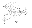
FIG. 2 is a perspective view of a system for manufacturing test membranes according to one embodiment of the present invention. -
FIG. 3a is a perspective view of dipping system for applying a reagent to a test membrane according to one embodiment of the present invention. -
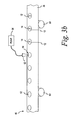
FIG. 3b is a perspective view of pumping system for applying a reagent to a test membrane according to an alternative embodiment of the present invention. -
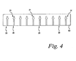
FIG. 4 is a top perspective view of a substrate having a plurality of capillary channels formed therein according to one embodiment of the present invention. -
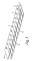
FIG. 5 is a perspective view of a plurality of test membrane disks attached to a carrier and a substrate having a plurality of capillary channels formed therein according to one embodiment of the present invention. -
FIG. 6 is a perspective view of a system for laminating the test membrane disks attached to a carrier to a substrate having a plurality of capillary channels formed therein according to one embodiment of the present invention. -
FIG. 7 is a perspective view of a stamping system for cutting a test sensor from a sheet of test sensors according to one embodiment of the present invention. -
FIG. 8 is a side view of a cartridge having a reel of test membranes disposed therein according to an alternative embodiment of the present invention. -
FIG. 9 is a side view of a dispensing cartridge having a reel of test membranes disposed therein and a collecting cartridge according to another alternative embodiment of the present invention. - While the invention is susceptible to various modifications and alternative forms, specific embodiments will be shown by way of example in the drawings and will be described in detail herein. It should be understood, however, that the invention is not intended to be limited to the particular forms disclosed. Rather, the invention is to cover all modifications, equivalents, and alternatives falling within the scope of the invention as defined by the appended claims.
- Turning now to the drawings and initially to
FIG. 1 , atest sensor 10 is shown according to one embodiment of the present invention. Thetest sensor 10 is used in the harvesting and analysis of a liquid sample for determining the presence or concentration of an analyte in the liquid sample. Thetest sensor 10 includes atest membrane disk 12 having areagent 14 disposed therein. Thetest membrane disk 12 is adhered to the underside (as viewed inFIG. 1 ) of acarrier strip 16. Thecarrier strip 16 is laminated to abase 18 of the test sensor such that thetest membrane disk 12 downwardly extends into areaction area 21 of acapillary channel 20 formed in thebase 18. Thecarrier strip 16 forms a lid over thecapillary channel 20. - When conducting an assay, a liquid sample is harvested by positioning an
inlet 22 of thecapillary channel 20 adjacent the sample. The sample is moved, via capillary action, from theinlet 22 to thereaction area 21 where an analyte in the sample reacts with the reagent disposed in thetest membrane 12. Optionally, thecarrier 16 is positioned on the base 18 such that the upstream end of thecapillary channel 20 remains uncovered to form avent 23 to facilitate movement of the fluid sample in the capillary channel. Once the sample is moved into the reaction area, the analyte of interest (e.g., glucose) reacts with thereagent 14 on thetest membrane disk 12 and that reaction is measured with an optical device as previously described in the Background Section. - According to one embodiment of the present invention, the
capillary channel 20 is sized to provide underfill protection so that a required volume of sample is delivered to thereaction area 21. Additionally thecapillary channel 20 is widened to increase the lateral flow of the sample to thetest membrane disk 12 by enlarging the surface area of thetest membrane disk 12 periphery exposed to the sample flow in thecapillary channel 20. Thetest sensor 10base 18 is dimensioned to create a small gap between the side walls of thecapillary channel 20 and the edges of the test membrane, the bottom wall of thecapillary channel 20 and the bottom surface of the membrane, or both. These gaps provide a clearance to allow the flow of the sample across the bottom surface and edges of thetest membrane disk 12, which decreases saturation time and uniformity of the assay. These gaps between the edge and bottom of thetest membrane disk 12 and thecapillary channel 20 can range between about 0.0005 inch (about 0.0127 mm) and about 0.001 inch (about 0.0254 mm). In other alternative embodiments, a wicking membrane or mesh is attached to thetest membrane 12 to draw and diffuse the sample across thetest membrane 12 to increase the flow of the sample across thetest membrane disk 12. - According to one embodiment of the present invention, the
test membranes 12 are made of a hydrophilic polyethersulfone material having pore sizes ranging from about 0.2 to about 8 micrometers. The Presense membrane and the Predator® membrane, both manufactured by Pall Specialty Materials of Port Washington, New York, are two examples of commercially available test membranes that may be used in various embodiments of the present invention. Alternatively, the test membrane may be made of a nitrocellulose material. While thetest membrane disks 12 shown inFIG. 1 are disk-shaped, the test membranes can be of any shape in alternative embodiments of the present invention. - The
carrier 16 and the base 18 are both constructed of plastic. According to one embodiment of the present invention, thecarrier 16 and the base 18 are constructed of plastic having a surface tension of less than about 45 milli-Newtons per meter such as polystyrene, polypropylene, polyethylene, p olyethylene t erephthalate, polycarbonate, and polyvinyl chloride, for example. Thecarrier 16 andbase 18 are constructed of a somewhat hydrophobic material so as not to absorb thereagent 14 or the sample that moves through thecapillary channel 20 formed in the base 18 according to one embodiment of the present invention. Further, these materials are not adversely affected by the liquid samples (e.g., blood, urine, or saliva) to be tested. Thecarrier 16 is substantially optically transparent allowing the reaction between the analyte in the sample and the reagent to be optically measured through thecarrier 16. - The dimensions of the
test sensor 10 according to one embodiment of the present invention are as follows. Thecapillary channel 20 has a width ranging between about 1 mm and about 2 mm, with thereaction area 21 having a diameter of about 3-5 mm. Thetest membrane disk 12 has a diameter of about 2.5 to about 3.5 mm. In other embodiments, thetest membrane disk 12 has a diameter of about 1 to about 2 mm, thereaction area 21 has a diameter of about 1.5 to about 2.5 mm, and thecapillary channel 20 has a width of 0.75 to about 1 mm. Thereaction area 21 has a depth of about 0.10 to about 0.20 mm, leaving clearance between the bottom surface of thereaction area 21 and thetest membrane disk 12. This clearance increases fluid sample flow across the bottom surface of thetest membrane disk 12. - Referring also to
FIG. 2 , a method of manufacturing thetest sensor 10 according to one embodiment of the present invention will be described. The membrane material (i.e., the material from whichtest membrane disks 12 are cut) and the carrier material (i.e., the material from which thecarrier 16 is cut) are stored on afirst roll 24 and asecond roll 26, respectively. An adhesive liner, for adhering the membrane material to the carrier material, is disposed on athird roll 28. The adhesive liner that adheres thetest membrane disk 12 to the carrier 16 (formed from the carrier web 34) comprises a substantially optically clear adhesive for permitting thetest membrane disk 12 to be read through the substantially opticallyclear carrier 16. Atest membrane web 30 from thefirst roll 24, anadhesive liner web 32 from thethird roll 28, and acarrier web 34 from thethird roll 26 are fed between a cylindrical, rotatingdie 36 andcounter pressure roller 38 that crush-cut thetest membrane web 30 and theadhesive liner web 32 onto thecarrier web 34. Thecarrier web 34 is not cut resulting in a continuous membrane/carrier strip 40 having individual, cuttest membrane disks 12 adhered thereto and spaced apart by a predetermined distance. The excess adhesive liner material andtest membrane material 42 are lifted from the membrane/carrier strip 40 by a withdrawroller 44. - Turning now to
FIG. 3a , the membrane/carrier strip 40 is dipped into atank 50 containing a liquid reagent for impregnating thetest membrane disks 12 with thereagent 14. As the membrane/carrier strip 40 is directed into thetank 50, via a plurality ofrollers 51a-c, thetest membrane disks 12 absorb thereagent 14. Thecarrier 34 does not absorb any of thereagent 14 due to its hydrophobic nature. Thus, only thetest membrane disks 12 absorb thereagent 14. - Only the portions of the membrane material to be used (e.g., the test membrane disks 12) and not any excess membrane material absorb the costly reagent because the
test membrane disks 12 have been cut to the appropriate size for insertion into a test sensor base 18 (FIG. 1 ) prior to being impregnated with the reagent. In addition to the size of thetest membranes 12, further measures may be implemented for controlling the amount ofreagent 14 absorbed by thetest membrane disks 12 in alternative embodiments of the present invention. The speed at which the membrane/carrier strip 40 is advanced into thetank 50 ofreagent 14 can be varied to control the amount of time eachtest membrane disks 12 spends dipped in thereagent 14. The degree of impregnation of eachtest membrane disk 12 is directly proportional to the amount of time that thetest membrane disk 12 is dipped into thereagent 14. Additionally, apertures may be formed in thecarrier web 34 so that thetest membrane disks 12 absorb thereagent 14 from both sides. In such an embodiment, the time in which eachtest membrane disk 12 is dipped into thereagent 14 may be decreased because each testmembrane d isk 12 is absorbingreagent 14 from both sides which increases the test membrane disk's 12 rate ofreagent 14 absorption. - Referring to
FIG. 3b , an alternative embodiment for disposing thereagent 14 on thetest membrane disks 12 is illustrated. The membrane/carrier strip 40 is moved past anozzle 52, via a plurality ofrollers 53, that is in fluid communication with apump 54 for pumping thereagent 14 though thenozzle 52. Thenozzle 52 directs thereagent 14 onto thetest membrane disks 12. Thepump 54 controls the amount ofreagent 14 deposited on eachtest membrane disk 12. - Referring to
FIG. 4 , apolymer substrate 60 is provided from which the test sensor bodies 18 (FIG. 1 ) are formed. As discussed above, thebodies 18 are constructed of a polymer material so that the liquid sample to be analyzed is not absorbed by thetest sensor base 18. A plurality ofcapillary channels 20, including thereaction areas 21, are formed in thepolymer substrate 60. Thecapillary channels 20 are formed in thesubstrate 60 by any one of a variety of known manufacturing processes including flat bed embossing or rotary embossing. The process of embossing thecapillary channel 20 into thepolymer substrate 60 is performed using a continuous web process, similar to the method described above for cutting thetest membrane disks 12 from the web of membrane material 12 (FIG. 2 ). A long length of the substrate may be formed in a reel format or in a sheet format having a specific number (e.g., 5, 10 or 20) of capillary channels formed therein. - Referring to
FIG. 5 , thepolymer substrate 60 having thecapillary channels 20 formed therein is attached to the membrane/carrier strip 40 comprising thecarrier 16 and the plurality oftest membrane disks 12 disposed thereon. The membrane/carrier strip 40 is disposed on thepolymer substrate 60 such that thetest membrane disks 12 extends into thereaction areas 21 of thecapillary channels 20 formed in thepolymer substrate 60. The membrane/carrier strip 40 is laminated to thesubstrate 60 using an adhesive. According to alternative embodiments of the present invention, the adhesive may be applied to thepolymer substrate 60 prior to or subsequent to forming thecapillary channels 20 in thesubstrate 60. According to one embodiment of the present invention, the adhesive used to laminate the membrane/carrier strip 40 to the polymer substrate is heat and pressure sensitive. An example of an adhesive for use with the present invention is described inU.S. Patents Nos. 5,759,364 and5,798,031 , each of which is incorporated herein by reference in its entirety. - Referring to
FIG. 6 , a continuous process for laminating the membrane/carrier strip 40 to thepolymer substrate 60 is illustrated according to one embodiment of the present invention. Thesubstrate 60 and the membrane/carrier strip 40 are fed between a pair ofrollers substrate 60 and the membrane/carrier strip 40 together. For example, according to one embodiment of the present invention, thecapillary channels 20 are formed in a length ofsubstrate 60 that is fed betweenrollers carrier strip 40, wherein the membrane/carrier strip 40 is fed directly from the dipping process illustrated inFIG. 2 for forming a continuous length 76 oftest sensors 10. Alternatively, non-continuous sheets of test sensors 10 (e.g., 5, 10, or 15 test sensors) such as shown inFIG. 5 , are laminated to asubstrate 60 having the same number ofcapillary channels 20 formed therein. - Referring to
FIG. 7 ,individual test sensors 10 are cut from a length 80 a plurality oftest sensors 10. According to the illustrated embodiment, thetest sensors 10 are cut from the length 80 oftest sensors 10 using a stamping process. The length 80 is fed into a stamping die 82 which contains a die to cut out theindividual test sensors 10. After stamping, the individual test sensors are packaged. In an alternative embodiment, thetest sensors 10 are cut from the length 80 oftest sensors 10 using a blade, rather than a stamping die. - As indicated in the discussion above, the manufacturing steps described in connection with
FIGS. 2-7 may be part of a continuous manufacturing process wherein the stages are disposed along an manufacturing line. For example, the membrane/carrier strip 40 formed as described in connection withFIG. 2 may be fed directly into the reagent t ank 50 discussed inconnection with F IG. 3a, or past the nozzle as described in connection withFIG. 3b . Alternatively, the various manufacturing stages ofFIGS. 2-7 may be implemented in a non-continuous processes. For example, a reel of the membrane/carrier strip 40 may be formed (FIG. 2 ) and then that reel is later fed into thereagent tank 50 discussed in connection withFIG. 3a . - According to an alternative embodiment of the present invention, the reagent is applied to the
test membrane disks 12 of thetest sensors 10 by pumping the reagent 14 o nto t he t est m embraned isks 12. In s uch an e mbodiment, thetest membranes disks 12 are die-cut onto thepolymer carriers 14 as described above in connection withFIG. 2 . However, instead of dipping the carrier/membrane strip 40 into thereagent tank 50 as described in connection withFIG. 3a , the carrier/membrane strip 40 is advanced past areagent pump 54 as illustrated inFIG. 3b for depositing a predetermined amount ofreagent 14 onto each of thetest membrane disks 12. This method is also advantageous because the amount ofreagent 14 deposited onto each thetest membrane 12 is controlled by the pump. In another embodiment of the present invention, the reagent is deposited or "ink-jetted" onto the test membranes by use of a plurality of piezoelectric controlled nozzles as are commonly used for depositing ink on paper in ink jet printers. - While the test s
ensor 10 has been d escribed thus far as having a two piece construction (i.e., abase 18 and a carrier 16) with the acapillary channel 20 formed in the base, the test sensor can be have a three piece construction with the capillary channel c ut in a middle piece in alternative e mbodiments o f the present invention. For example, a flat base, a generally U-shaped middle layer, and a flat lid are adhered together. The side walls of the capillary channel are formed by the interior of the U-shaped middle layer. A test membrane disk, which is attached to the lid as described in connection withFIG. 1 , is positioned within the closed end of the U-shaped middle layer and the open end of the U-shaped middle layer forms the inlet of the capillary channel. - Referring to
FIG. 8 , in another embodiment of the present invention, areel 90 of the membrane/carrier strip 40 formed as described in c onnection w ith F IG. 2 is disposed with a dispensingcartridge 92 for dispensingtest membrane disks 94 impregnated with a reagent attached to acarrier 96 one at a time. According to one embodiment of the present invention, thecartridge 92 includes a cutting means (e.g., a sharp or serrated edge) for cutting thecarrier 96 for dispensing onetest membrane disk 94 at a time. Alternatively, thecarrier 96 is perforated betweentest membrane disks 94 during manufacturing to facilitate the tearing off of a singletest membrane disk 94 from thereel 90. The individually dispensedtest membrane disks 94 can be used with a top-fill device for determining the concentration of an analyst in a liquid sample according to an alternative embodiment of the present invention. - Referring to
FIG. 9 , in another embodiment of the p resent invention, areel 100 of the membrane/carrier strip 40 formed as described in connection withFIG. 2 is disposed with a dispensingcartridge 102 for dispensingtest membrane disks 104 impregnated with a reagent attached to acarrier 106 one at a time, similar to that described in connection withFIG. 8 . A collectingcartridge 110 collects the usedtest membrane disks 104. According to one embodiment, the dispensing and collectingcartridges test membrane disk 104 dispensed from the dispensingcartridge 102. The top-fill device includes alight source 114 for illuminating the test membrane disk having a sample deposited thereon and alight detector 116 for measuring light reflected from the reaction of the analyte in the body fluid and the reagent on thetest membrane disk 12 as is known in the art for determining the concentration of the analyte in the body fluid. - While the invention is susceptible to various modifications and alternative forms, specific embodiments thereof have been shown by way of example in the drawings and herein described in detail. It should be understood, however, that it is not intended to limit the invention to the particular forms disclosed, but on the contrary, the intention is to cover all modifications, equivalents, and alternatives falling within the scope of the invention as defined by the appended claims.
Claims (8)
- A method for manufacturing a test sensor (10) for use in the determination of an analyte in a liquid sample, the method comprising:providing a substantially hydrophobic polymer carrier (16) having a first surface;adhering a test membrane (12) to the first surface of the polymer carrier (16), the test membrane (12) adapted to absorb a reagent (14);impregnating the test membrane (12) with a reagent (14);providing a base (18) having a capillary channel (20) formed therein; andadhering the first surface of the carrier (16) to the base (18),characterized in thatthe test membrane (12) extends into the capillary channel (20) formed in base (18) such that the test membrane (12) is arranged to allow flow of the liquid sample across a bottom surface and an edge of the test membrane (12).
- The method of claim 1 wherein the reagent (14) is adapted to produce a colorimetric reaction indicative of the concentration of the analyte in the sample.
- The method of claim 1 or 2 wherein adhering comprises:disposing a length of an adhesive liner (32) on a length of the polymer carrier (34);disposing a length of test membrane material (30) on the length of adhesive liner (32);crush-cutting a plurality of individual test membrane sections from the length of the test membrane material (30) ;adhering the plurality of individual test membrane sections to the polymer carrier (34); andremoving the excess membrane material (30) and adhesive liner (32).
- The method of one of the claims 1 to 3 further comprising forming one or more apertures in the polymer carrier (34).
- An optical-based test sensor (10) for use in the determination of an analyte in a liquid sample, the test sensor (10) comprising:a base (18) having a capillary channel (20) formed in a surface of the base (18), the capillary channel (20) adapted to move a liquid sample from an inlet (22) to a reaction area (21) formed in the base (18);a polymer carrier (16) having a lower surface adhered to the surface of the base (18), the polymer carrier (16) being disposed over at least a portion of the capillary channel (20); anda test membrane (12) adhered to the lower surface of the polymer carrier (16), the test membrane (12) containing a reagent (14),characterized in that the test membrane (12) extends from the polymer carrier (16) into the reaction area (21) such that the test membrane (12) is arranged to allow the flow of the liquid sample across a bottom surface and an edge of the test membrane (12).
- The test sensor (10) of claim 5 wherein the reagent (14) is adapted to produce a colorimetric reaction indicative of the concentration of the analyte in the sample.
- The test sensor (10) of claim 5 or 6 wherein the carrier (16) is constructed of a substantially hydrophobic material.
- The test sensor (10) of one of the claims 5 to 7 wherein the capillary channel (20) has an inlet end and an opposite end, the opposite end being uncovered by the carrier (16).
Priority Applications (1)
| Application Number | Priority Date | Filing Date | Title |
|---|---|---|---|
| EP10172250A EP2314376A1 (en) | 2003-05-29 | 2004-05-26 | Test sensor and method for manufacturing the same |
Applications Claiming Priority (2)
| Application Number | Priority Date | Filing Date | Title |
|---|---|---|---|
| US47370303P | 2003-05-29 | 2003-05-29 | |
| US473703P | 2003-05-29 |
Publications (2)
| Publication Number | Publication Date |
|---|---|
| EP1482299A1 EP1482299A1 (en) | 2004-12-01 |
| EP1482299B1 true EP1482299B1 (en) | 2010-09-01 |
Family
ID=33131951
Family Applications (2)
| Application Number | Title | Priority Date | Filing Date |
|---|---|---|---|
| EP10172250A Withdrawn EP2314376A1 (en) | 2003-05-29 | 2004-05-26 | Test sensor and method for manufacturing the same |
| EP04012423A Expired - Lifetime EP1482299B1 (en) | 2003-05-29 | 2004-05-26 | Test sensor and method for manufacturing the same |
Family Applications Before (1)
| Application Number | Title | Priority Date | Filing Date |
|---|---|---|---|
| EP10172250A Withdrawn EP2314376A1 (en) | 2003-05-29 | 2004-05-26 | Test sensor and method for manufacturing the same |
Country Status (6)
| Country | Link |
|---|---|
| US (2) | US8153081B2 (en) |
| EP (2) | EP2314376A1 (en) |
| JP (1) | JP2004354388A (en) |
| AU (1) | AU2004202232A1 (en) |
| CA (1) | CA2468472A1 (en) |
| DE (1) | DE602004028894D1 (en) |
Cited By (2)
| Publication number | Priority date | Publication date | Assignee | Title |
|---|---|---|---|---|
| EP2811299A1 (en) | 2013-06-07 | 2014-12-10 | Roche Diagniostics GmbH | Test element for detecting at least one analyte in a body fluid |
| US10094817B2 (en) | 2014-02-14 | 2018-10-09 | Roche Diagnostics Operations, Inc. | Process and production device for the production of at least one analytical device |
Families Citing this family (18)
| Publication number | Priority date | Publication date | Assignee | Title |
|---|---|---|---|---|
| DE102004046366A1 (en) * | 2004-07-15 | 2006-02-09 | Levin, Felix, Dr. | Rapid chemical analysis system for urine or other biological fluids has pipette with rubber balloon and chemical reagent on inside surface of balloon or in filter plug |
| RU2007114909A (en) * | 2004-09-20 | 2008-11-10 | БАЙЕР ХЕЛТКЭА ЭлЭлСи (US) | BLOODED KNIFE DEVICE FOR DISTRIBUTING GLUCOSE LEVEL SENSORS IN BLOOD |
| US7280201B2 (en) * | 2004-12-17 | 2007-10-09 | Avago Technologies General Ip Pte Ltd | Sensor having integrated light detector and/or light source |
| JP2006308419A (en) * | 2005-04-28 | 2006-11-09 | Fuji Photo Film Co Ltd | Microchip and analysis method using same |
| EP1717585B1 (en) | 2005-04-28 | 2013-01-16 | FUJIFILM Corporation | Microchip and analysis method using the same |
| US7312042B1 (en) | 2006-10-24 | 2007-12-25 | Abbott Diabetes Care, Inc. | Embossed cell analyte sensor and methods of manufacture |
| CA2798716A1 (en) | 2011-12-13 | 2013-06-13 | Endochoice Innovation Center Ltd. | Removable tip endoscope |
| CN103234962A (en) * | 2013-05-09 | 2013-08-07 | 董建国 | Vaginal micro-ecological environment sensor and manufacturing method thereof |
| CA2912947C (en) * | 2013-05-22 | 2017-06-20 | Imec Vzw | Compact fluid analysis device and method to fabricate |
| US10101342B2 (en) | 2014-02-12 | 2018-10-16 | Church & Dwight Co., Inc. | Devices and methods for electronic analyte assaying |
| JP2015232550A (en) * | 2014-05-13 | 2015-12-24 | アークレイ株式会社 | Sensor body, manufacturing method of sensor body, and sensor cartridge |
| PL3356546T3 (en) | 2015-09-29 | 2020-11-16 | Polymer Technology Systems, Inc. | Systems for a lateral flow test strip holder |
| KR102224729B1 (en) | 2016-12-23 | 2021-03-08 | 라디오미터 메디컬 에이피에스 | Multi-use body fluid sensor assembly |
| JP6696592B2 (en) * | 2017-01-05 | 2020-05-20 | 株式会社島津製作所 | Sampling chip dividing device |
| EP3409362B1 (en) * | 2017-05-31 | 2024-04-03 | Roche Diabetes Care GmbH | Method for manufacturing a test element for detecting an analyte in a body fluid, test element and method of use |
| CN111323573B (en) * | 2020-03-02 | 2025-07-29 | 欧蒙医学诊断(中国)有限公司 | Sample adding indicating strip and incubation plate with same |
| WO2023070567A1 (en) * | 2021-10-29 | 2023-05-04 | 京东方科技集团股份有限公司 | Detection chip and preparation method therefor |
| US20230312209A1 (en) * | 2022-04-05 | 2023-10-05 | 10X Genomics, Inc. | Blister packs and uses thereof |
Family Cites Families (45)
| Publication number | Priority date | Publication date | Assignee | Title |
|---|---|---|---|---|
| US4756884A (en) | 1985-08-05 | 1988-07-12 | Biotrack, Inc. | Capillary flow device |
| US4761381A (en) | 1985-09-18 | 1988-08-02 | Miles Inc. | Volume metering capillary gap device for applying a liquid sample onto a reactive surface |
| US5049487A (en) | 1986-08-13 | 1991-09-17 | Lifescan, Inc. | Automated initiation of timing of reflectance readings |
| US4935346A (en) | 1986-08-13 | 1990-06-19 | Lifescan, Inc. | Minimum procedure system for the determination of analytes |
| DE3630999A1 (en) | 1986-09-12 | 1988-03-17 | Boehringer Mannheim Gmbh | MULTI-LAYER TEST CARRIER |
| US4753776A (en) | 1986-10-29 | 1988-06-28 | Biotrack, Inc. | Blood separation device comprising a filter and a capillary flow pathway exiting the filter |
| US4895798A (en) | 1987-11-13 | 1990-01-23 | Miles, Inc. | Test devices for determination of occult blood |
| US5472671A (en) | 1989-04-26 | 1995-12-05 | Nilsson; Sven-Erik | Cuvette |
| US6395227B1 (en) * | 1989-08-28 | 2002-05-28 | Lifescan, Inc. | Test strip for measuring analyte concentration over a broad range of sample volume |
| DE69023476T2 (en) | 1990-02-22 | 1996-03-21 | Editek Inc | Multi-layer test device for the determination of substances in liquids. |
| JPH05157745A (en) | 1991-12-09 | 1993-06-25 | Dainippon Printing Co Ltd | Inspection body |
| US6156270A (en) | 1992-05-21 | 2000-12-05 | Biosite Diagnostics, Inc. | Diagnostic devices and apparatus for the controlled movement of reagents without membranes |
| US5843691A (en) | 1993-05-15 | 1998-12-01 | Lifescan, Inc. | Visually-readable reagent test strip |
| DE4326339A1 (en) | 1993-08-05 | 1995-02-09 | Boehringer Mannheim Gmbh | System for analysis of sample liquids |
| US5700695A (en) | 1994-06-30 | 1997-12-23 | Zia Yassinzadeh | Sample collection and manipulation method |
| DE19523049A1 (en) | 1995-06-24 | 1997-01-02 | Boehringer Mannheim Gmbh | Multilayer analysis element for the determination of an analyte in a liquid |
| US5518689A (en) | 1995-09-05 | 1996-05-21 | Bayer Corporation | Diffused light reflectance readhead |
| US5611999A (en) | 1995-09-05 | 1997-03-18 | Bayer Corporation | Diffused light reflectance readhead |
| US5723284A (en) | 1996-04-01 | 1998-03-03 | Bayer Corporation | Control solution and method for testing the performance of an electrochemical device for determining the concentration of an analyte in blood |
| US5962215A (en) | 1996-04-05 | 1999-10-05 | Mercury Diagnostics, Inc. | Methods for testing the concentration of an analyte in a body fluid |
| DE19629656A1 (en) | 1996-07-23 | 1998-01-29 | Boehringer Mannheim Gmbh | Diagnostic test carrier with multilayer test field and method for the determination of analyte with its aid |
| US6093156A (en) | 1996-12-06 | 2000-07-25 | Abbott Laboratories | Method and apparatus for obtaining blood for diagnostic tests |
| JP2953418B2 (en) | 1997-01-09 | 1999-09-27 | 日本電気株式会社 | Biochemical analyzer |
| US5759364A (en) | 1997-05-02 | 1998-06-02 | Bayer Corporation | Electrochemical biosensor |
| US5798031A (en) | 1997-05-12 | 1998-08-25 | Bayer Corporation | Electrochemical biosensor |
| US6300138B1 (en) | 1997-08-01 | 2001-10-09 | Qualigen, Inc. | Methods for conducting tests |
| DE19753847A1 (en) * | 1997-12-04 | 1999-06-10 | Roche Diagnostics Gmbh | Analytical test element with capillary channel |
| JP3761698B2 (en) * | 1997-12-24 | 2006-03-29 | 理想科学工業株式会社 | Stencil printing machine |
| DE19815684A1 (en) | 1998-04-08 | 1999-10-14 | Roche Diagnostics Gmbh | Process for the preparation of analytical aids |
| US6181417B1 (en) | 1998-04-20 | 2001-01-30 | Bayer Corporation | Photometric readhead with light-shaping plate |
| US6521182B1 (en) | 1998-07-20 | 2003-02-18 | Lifescan, Inc. | Fluidic device for medical diagnostics |
| US6162397A (en) * | 1998-08-13 | 2000-12-19 | Lifescan, Inc. | Visual blood glucose test strip |
| CA2254223A1 (en) | 1998-11-16 | 2000-05-16 | Biophys, Inc. | Device and method for analyzing a biologic sample |
| US6368563B1 (en) | 1999-03-12 | 2002-04-09 | Integ, Inc. | Collection well for body fluid tester |
| JP2001272399A (en) | 2000-01-21 | 2001-10-05 | Wako Pure Chem Ind Ltd | Mult-item test tool, manufacturing method therefor, and test tool measuring device |
| US6403037B1 (en) | 2000-02-04 | 2002-06-11 | Cepheid | Reaction vessel and temperature control system |
| CN1180259C (en) | 2000-07-31 | 2004-12-15 | 松下电器产业株式会社 | biological sensor |
| JP3475228B2 (en) * | 2000-10-26 | 2003-12-08 | 株式会社スズケン | Capillary device provided with enzyme test paper used for analysis of trace sample, and measurement method |
| US6814843B1 (en) | 2000-11-01 | 2004-11-09 | Roche Diagnostics Corporation | Biosensor |
| US7776608B2 (en) | 2001-07-09 | 2010-08-17 | Bayer Healthcare Llc | Volume meter testing device and method of use |
| US6949297B2 (en) * | 2001-11-02 | 2005-09-27 | 3M Innovative Properties Company | Hybrid adhesives, articles, and methods |
| US6723500B2 (en) * | 2001-12-05 | 2004-04-20 | Lifescan, Inc. | Test strips having reaction zones and channels defined by a thermally transferred hydrophobic barrier |
| US20030143113A2 (en) | 2002-05-09 | 2003-07-31 | Lifescan, Inc. | Physiological sample collection devices and methods of using the same |
| US7604775B2 (en) * | 2002-08-12 | 2009-10-20 | Bayer Healthcare Llc | Fluid collecting and monitoring device |
| JP5157745B2 (en) | 2008-08-15 | 2013-03-06 | マツダ株式会社 | Vehicle side body structure |
-
2004
- 2004-05-14 US US10/845,026 patent/US8153081B2/en active Active
- 2004-05-21 AU AU2004202232A patent/AU2004202232A1/en not_active Abandoned
- 2004-05-26 EP EP10172250A patent/EP2314376A1/en not_active Withdrawn
- 2004-05-26 EP EP04012423A patent/EP1482299B1/en not_active Expired - Lifetime
- 2004-05-26 CA CA002468472A patent/CA2468472A1/en not_active Abandoned
- 2004-05-26 DE DE602004028894T patent/DE602004028894D1/en not_active Expired - Lifetime
- 2004-05-28 JP JP2004158599A patent/JP2004354388A/en active Pending
-
2012
- 2012-03-09 US US13/416,611 patent/US8506903B2/en not_active Expired - Lifetime
Cited By (4)
| Publication number | Priority date | Publication date | Assignee | Title |
|---|---|---|---|---|
| EP2811299A1 (en) | 2013-06-07 | 2014-12-10 | Roche Diagniostics GmbH | Test element for detecting at least one analyte in a body fluid |
| US10029252B2 (en) | 2013-06-07 | 2018-07-24 | Roche Diabetes Care, Inc. | Test elements for detecting at least one analyte in a body fluid, as well as methods of manufacturing the same |
| US10150114B2 (en) | 2013-06-07 | 2018-12-11 | Roche Diabetes Care, Inc. | Test elements for detecting at least one analyte in a body fluid, as well as methods of manufacturing the same |
| US10094817B2 (en) | 2014-02-14 | 2018-10-09 | Roche Diagnostics Operations, Inc. | Process and production device for the production of at least one analytical device |
Also Published As
| Publication number | Publication date |
|---|---|
| EP2314376A1 (en) | 2011-04-27 |
| US8506903B2 (en) | 2013-08-13 |
| CA2468472A1 (en) | 2004-11-29 |
| US8153081B2 (en) | 2012-04-10 |
| EP1482299A1 (en) | 2004-12-01 |
| US20120230874A1 (en) | 2012-09-13 |
| JP2004354388A (en) | 2004-12-16 |
| US20040241881A1 (en) | 2004-12-02 |
| DE602004028894D1 (en) | 2010-10-14 |
| AU2004202232A1 (en) | 2004-12-16 |
Similar Documents
| Publication | Publication Date | Title |
|---|---|---|
| US8506903B2 (en) | Test sensor and method for manufacturing the same | |
| JP3339836B2 (en) | Method for manufacturing analytical device | |
| US8252248B2 (en) | Analytical test element | |
| CA1115186A (en) | Multilayered test device for determining the presence of a liquid sample component, and method of use | |
| EP0993614B1 (en) | Device for determination of an analyte in a body fluid | |
| CA2590855C (en) | Self-contained test sensor | |
| EP1369686B1 (en) | Analyte concentration determination meters and methods of using the same | |
| US7008799B1 (en) | Analytical test element with a capillary channel | |
| US7820451B2 (en) | Analytical test element | |
| US5047206A (en) | Reagent test strip | |
| US20010039057A1 (en) | Devices for testing for the presence and/or concentration of an analyte in a body fluid | |
| RU2418300C2 (en) | Applying reagent onto matrix material | |
| HK1107539A (en) | Analytical test element | |
| MXPA99003180A (en) | Process for the production of analiti devices | |
| HK1058703B (en) | Analyte concentration determination meters and methods of using the same |
Legal Events
| Date | Code | Title | Description |
|---|---|---|---|
| PUAI | Public reference made under article 153(3) epc to a published international application that has entered the european phase |
Free format text: ORIGINAL CODE: 0009012 |
|
| AK | Designated contracting states |
Kind code of ref document: A1 Designated state(s): AT BE BG CH CY CZ DE DK EE ES FI FR GB GR HU IE IT LI LU MC NL PL PT RO SE SI SK TR |
|
| AX | Request for extension of the european patent |
Extension state: AL HR LT LV MK |
|
| 17P | Request for examination filed |
Effective date: 20050601 |
|
| AKX | Designation fees paid |
Designated state(s): DE FR GB IT |
|
| RAP1 | Party data changed (applicant data changed or rights of an application transferred) |
Owner name: BAYER HEALTHCARE LLC |
|
| 17Q | First examination report despatched |
Effective date: 20070131 |
|
| GRAP | Despatch of communication of intention to grant a patent |
Free format text: ORIGINAL CODE: EPIDOSNIGR1 |
|
| GRAS | Grant fee paid |
Free format text: ORIGINAL CODE: EPIDOSNIGR3 |
|
| GRAA | (expected) grant |
Free format text: ORIGINAL CODE: 0009210 |
|
| RAP1 | Party data changed (applicant data changed or rights of an application transferred) |
Owner name: BAYER HEALTHCARE LLC |
|
| AK | Designated contracting states |
Kind code of ref document: B1 Designated state(s): DE FR GB IT |
|
| REG | Reference to a national code |
Ref country code: GB Ref legal event code: FG4D |
|
| REF | Corresponds to: |
Ref document number: 602004028894 Country of ref document: DE Date of ref document: 20101014 Kind code of ref document: P |
|
| PG25 | Lapsed in a contracting state [announced via postgrant information from national office to epo] |
Ref country code: IT Free format text: LAPSE BECAUSE OF FAILURE TO SUBMIT A TRANSLATION OF THE DESCRIPTION OR TO PAY THE FEE WITHIN THE PRESCRIBED TIME-LIMIT Effective date: 20100901 |
|
| PLBE | No opposition filed within time limit |
Free format text: ORIGINAL CODE: 0009261 |
|
| STAA | Information on the status of an ep patent application or granted ep patent |
Free format text: STATUS: NO OPPOSITION FILED WITHIN TIME LIMIT |
|
| 26N | No opposition filed |
Effective date: 20110606 |
|
| PGFP | Annual fee paid to national office [announced via postgrant information from national office to epo] |
Ref country code: DE Payment date: 20110527 Year of fee payment: 8 |
|
| REG | Reference to a national code |
Ref country code: DE Ref legal event code: R097 Ref document number: 602004028894 Country of ref document: DE Effective date: 20110606 |
|
| GBPC | Gb: european patent ceased through non-payment of renewal fee |
Effective date: 20110526 |
|
| REG | Reference to a national code |
Ref country code: FR Ref legal event code: ST Effective date: 20120131 |
|
| PG25 | Lapsed in a contracting state [announced via postgrant information from national office to epo] |
Ref country code: FR Free format text: LAPSE BECAUSE OF NON-PAYMENT OF DUE FEES Effective date: 20110531 |
|
| PG25 | Lapsed in a contracting state [announced via postgrant information from national office to epo] |
Ref country code: GB Free format text: LAPSE BECAUSE OF NON-PAYMENT OF DUE FEES Effective date: 20110526 |
|
| REG | Reference to a national code |
Ref country code: DE Ref legal event code: R119 Ref document number: 602004028894 Country of ref document: DE Effective date: 20121201 |
|
| PG25 | Lapsed in a contracting state [announced via postgrant information from national office to epo] |
Ref country code: DE Free format text: LAPSE BECAUSE OF NON-PAYMENT OF DUE FEES Effective date: 20121201 |