EP1482284A1 - Flow sensor - Google Patents
Flow sensor Download PDFInfo
- Publication number
- EP1482284A1 EP1482284A1 EP20040011940 EP04011940A EP1482284A1 EP 1482284 A1 EP1482284 A1 EP 1482284A1 EP 20040011940 EP20040011940 EP 20040011940 EP 04011940 A EP04011940 A EP 04011940A EP 1482284 A1 EP1482284 A1 EP 1482284A1
- Authority
- EP
- European Patent Office
- Prior art keywords
- section
- detection section
- flow sensor
- pipe line
- flow
- Prior art date
- Legal status (The legal status is an assumption and is not a legal conclusion. Google has not performed a legal analysis and makes no representation as to the accuracy of the status listed.)
- Withdrawn
Links
Images


Classifications
-
- G—PHYSICS
- G01—MEASURING; TESTING
- G01F—MEASURING VOLUME, VOLUME FLOW, MASS FLOW OR LIQUID LEVEL; METERING BY VOLUME
- G01F1/00—Measuring the volume flow or mass flow of fluid or fluent solid material wherein the fluid passes through a meter in a continuous flow
- G01F1/05—Measuring the volume flow or mass flow of fluid or fluent solid material wherein the fluid passes through a meter in a continuous flow by using mechanical effects
- G01F1/20—Measuring the volume flow or mass flow of fluid or fluent solid material wherein the fluid passes through a meter in a continuous flow by using mechanical effects by detection of dynamic effects of the flow
- G01F1/32—Measuring the volume flow or mass flow of fluid or fluent solid material wherein the fluid passes through a meter in a continuous flow by using mechanical effects by detection of dynamic effects of the flow using swirl flowmeters
- G01F1/3209—Measuring the volume flow or mass flow of fluid or fluent solid material wherein the fluid passes through a meter in a continuous flow by using mechanical effects by detection of dynamic effects of the flow using swirl flowmeters using Karman vortices
-
- G—PHYSICS
- G01—MEASURING; TESTING
- G01F—MEASURING VOLUME, VOLUME FLOW, MASS FLOW OR LIQUID LEVEL; METERING BY VOLUME
- G01F1/00—Measuring the volume flow or mass flow of fluid or fluent solid material wherein the fluid passes through a meter in a continuous flow
- G01F1/05—Measuring the volume flow or mass flow of fluid or fluent solid material wherein the fluid passes through a meter in a continuous flow by using mechanical effects
- G01F1/20—Measuring the volume flow or mass flow of fluid or fluent solid material wherein the fluid passes through a meter in a continuous flow by using mechanical effects by detection of dynamic effects of the flow
- G01F1/32—Measuring the volume flow or mass flow of fluid or fluent solid material wherein the fluid passes through a meter in a continuous flow by using mechanical effects by detection of dynamic effects of the flow using swirl flowmeters
- G01F1/325—Means for detecting quantities used as proxy variables for swirl
- G01F1/3282—Means for detecting quantities used as proxy variables for swirl for detecting variations in infrasonic, sonic or ultrasonic waves, due to modulation by passing through the swirling fluid
-
- G—PHYSICS
- G01—MEASURING; TESTING
- G01F—MEASURING VOLUME, VOLUME FLOW, MASS FLOW OR LIQUID LEVEL; METERING BY VOLUME
- G01F15/00—Details of, or accessories for, apparatus of groups G01F1/00 - G01F13/00 insofar as such details or appliances are not adapted to particular types of such apparatus
- G01F15/06—Indicating or recording devices
- G01F15/061—Indicating or recording devices for remote indication
- G01F15/063—Indicating or recording devices for remote indication using electrical means
-
- G—PHYSICS
- G01—MEASURING; TESTING
- G01F—MEASURING VOLUME, VOLUME FLOW, MASS FLOW OR LIQUID LEVEL; METERING BY VOLUME
- G01F15/00—Details of, or accessories for, apparatus of groups G01F1/00 - G01F13/00 insofar as such details or appliances are not adapted to particular types of such apparatus
- G01F15/06—Indicating or recording devices
- G01F15/068—Indicating or recording devices with electrical means
Definitions
- This invention relates to a flow sensor for detecting the flow quantity of a fluid.
- an ultrasonic vortex flow sensor detects ultrasonically in a noncontact manner a Karman vortex occurring regularly downstream from a vertex generation pole placed in a flow.
- the ultrasonic vortex flow sensor can ultrasonically detect change in Karman vortex, thereby detecting the flow quantity with high accuracy in a wide flow quantity range.
- Such flow sensors include an integral-type flow sensor and a separate flow sensor.
- the integral-type flow sensor which has a flow quantity detection part and a flow quantity display part in one piece, becomes large.
- the separate flow sensor is made up of a detection section for detecting the flow quantity and a display section for displaying the value of the detected flow quantity.
- the detection section does not have a display section and thus can be miniaturized.
- FIG. 13 is an external perspective view of the detection section of the flow sensor in the related art
- FIG. 14 is an exploded perspective view of the detection section of the flow sensor in the related art.
- a detection section 900 has a casing 940 shaped like a rectangular parallelepiped and is provided with a through water pipe line 910 so as to pierce opposed sides of the casing 940.
- a circuit board 950 is placed above the through water pipe line 910.
- a cylindrical element storage part 920 is provided on both sides of the outer peripheral surface of the through water pipe line 910, and a transmitter 911 and a receiver 912 are inserted into the element storage parts 920.
- Each element storage part 920 is closed by a press member 930 having a convex part 9a at the center. Accordingly, the convex parts 9a of the press members 930 press the transmitter 911 and the receiver 912 against the outer peripheral surface of the through water pipe line 910.
- a taking-cut pipe 970 of a conductor KB of the transmitter 911 and the receiver 912 of the through water pipe line 910 is provided in the direction crossing the element storage parts 920.
- the press members 930 each having the convex part 9a at the center press the transmitter 911 and the receiver 912 against the outer peripheral surface of the through water pipe line 910, so that the size of the detection section 900 of the flow sensor in the related art becomes large in the direction in which the transmitter 911 and the receiver 912 are aligned and the size also becomes large.in the direction crossing the direction in which the transmitter 911 and the receiver 912 are aligned. Since such a structure is housed in the casing 940, the detection section 900 is upsized as a whole. Recently, making slim the detection section 900 has been desired.
- a f lowsensor including a detection section for detecting a flow quantity of a fluid, the detection section having a display section for displaying information based on the detected flow quantity; and a main unit section being provided as a separate body from the detection section for displaying the flow quantity detected by the detection section.
- the detection section detects the flow quantity of a fluid.
- the detected flow quantity is displayed on the main unit section provided as a separate body from the detection section.
- the information based on the detected flow quantity is displayed on the display section of the detection section.
- the detection section is provided with the display section for displaying the information based on the flow quantity, thus enabling the user to easily check the detection state of the flow quantity on the detection section.
- the display section may includes a plurality of light emission sections; and a control section for turning on the plurality of light emission sections in order at speed responsive to the detected flow quantity.
- the plurality of light emission sections are turned on in order at the speed responsive to the detected flow quantity, so that the user can easily recognize the flow of the fluid from a distance.
- the display section can be miniaturized and the detection section can also be miniaturized.
- the detection section may further include a Karman vortex detection section for ultrasonically detecting change in a Karman vortex of a fluid; and a pulse signal generation section for generating a pulse signal corresponding to the change in the Karman vortex detected by the Karman vortex detection section, and the control section may turn on the plurality of light emission sections in order based on the pulse signal generated by the pulse signal generation section.
- change in a Karman vortex of a fluid is ultrasonically detected and a pulse signal corresponding to the detected change in the Karman vortex is generated.
- the plurality of light emission sections are tuned on in order based on the pulse signal.
- the plurality of light emission sections are turned on in order at the speed corresponding to the flow quantity of the fluid, so that the user can visually recognize the flow of the fluid from a distance.
- the display section may display a level responsive to the detected flow quantity. In this case, since the level responsive to the detected flow quantity is displayed, the user can visually recognize the flow of the fluid from a distance.
- the detection section may include a pipe line through which a fluid passes; a vortex generation member being provided in the pipe line for generating a Karman vortex; a pair of ultrasonic devices being placed on an outer peripheral surface of the pipe line so as to be opposed to each other with the pipe line between; and a press member having a pair of press parts for pressing the pair of ultrasonic devices against the pipe line and a joint part for joining the pair of press parts.
- the pair of ultrasonic devices is placed on the outer peripheral surface of the pipe line so as to be opposed to each other with the pipe line between, and is pressed against the pipe line by the pair of press parts joined by the joint part of the press member.
- the detection section may include a casing having a width of a first length and a thickness of a second length smaller than the first length, and the pair of ultrasonic devices may be placed in the casing so as to be arranged in a width direction.
- the pair of ultrasonic devices is provided in the casing so as to be arranged in the width direction, so that the detection section can be miniaturized and made slim.
- the case may include a housing space for housing a circuit board connected to the display section provided so as to be adjacent to one of the ultrasonic devices in the width direction.
- the housing space for housing the circuit board is provided so as to be adjacent to one of the ultrasonic devices in the width direction in the casing, so that the detection section can be miniaturized and made slim.
- the case may include a hermetic seal space for hermetically sealing the pair of ultrasonic devices and a part of the pipe line.
- the hermetic seal space for hermetically sealing the pair of ultrasonic devices and a part of the pipe line is provided in the casing, so that the pair of ultrasonic devices and a part of the pipe line can be prevented from being contaminated by dust.
- the housing space and the hermetic seal space may be put into one piece.
- the housing space and the hermetic seal space are put into one piece, whereby the pair of ultrasonic devices, a part of the pipe line, and the circuit board can be prevented from being contaminated by dust.
- a transmitter transmits an ultrasonic wave
- a receiver receives the ultrasonic wave from the transmitter
- an output signal of the receiver is amplified
- aphase comparator outputs a voltage corresponding to the phase difference based on a high frequency signal generatedby ahigh frequency signal oscillator and an output signal of a high frequency signal amplifier.
- a low frequency amplifier amplifies the output voltage of the phase comparator
- a comparator compares the output signal of the low frequency amplifier with a reference voltage and outputs a pulse indicating the comparison result
- a frequency divider divides the output pulse
- a decoder decodes the output signal of the frequency divider for turning on light emission sections of a flow indicator in green in order.
- FIGS. 1 to 12 there are shown flow sensors according to first and second embodiments of the invention.
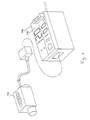
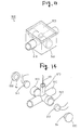
- FIG. 1 is a schematic drawing to show the configuration of a flow sensor according to a first embodiment of the invention.
- the flow sensor is made up of a detection section (sensor head) 100 and a main unit section (sensor main unit section) 200.
- the detection section 100 is connected to the main unit section 200 by a cable.
- the main unit section 200 has a display section 230.
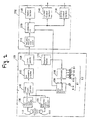
- FIG. 2 is a block diagram to show the configuration of the flow sensor according to the first embodiment of the invention. As shown in FIG. 2, the flow sensor is made up of the detection section 100 and the main unit section 200.
- the detection section 100 includes a transmitter 111, a receiver 112, a high frequency signal oscillator 120, a high frequency signal amplifier 130, a phase comparator 140, a low frequency amplifier 150, a comparator 160, a frequency divider 170, a decoder 180, a signal level determination unit 190, and a flow indicator LU.
- This flow indicator LU includes light emission sections 81 to 84.
- the light emission section 81 is made up of a red LED (light emitting diode) 81R and a green LED 81G. Each of the light emission sections 82 to 84 has a green LED.
- the transmitter 111 and the receiver 112 are implemented as ultrasonic devices, for example.
- the main unit section 200 includes a frequency measurement device 210, a computing unit 220, a display section 230, a control output section 240, and an analog output section 250.
- the frequency measurement device 210 and the computing unit 220 are implemented as a CPU (central processing unit), for example.
- the high frequency signal oscillator 120 generates a high frequency signal and gives the high frequency signal to the transmitter 111, which then transmits an ultrasonic wave.
- the receiver 112 receives the ultrasonic wave from the transmitter 111.
- the frequency of a Karman vortex occurring on a fluid changes due to the flow quantity of the fluid.
- the ultrasonic wave propagation time changes in proportion to the frequency of the Karman vortex. Therefore, change in the ultrasonic wave propagation time from the transmitter 111 to the receiver 112 is detected, whereby the flow quantity can be detected.
- the high frequency signal amplifier 130 amplifies an output signal of the receiver 112.
- the phase comparator 140 makes a phase comparison between the high frequency signal generated by the high frequency signal oscillator 120 and the output signal of the high frequency signal amplifier 130 and outputs a voltage corresponding to the phase difference.
- the low frequency amplifier 150 amplifies the output voltage of the phase comparator 140.
- the comparator 160 compares the output signal of the low frequency amplifier 150 with a reference voltage and outputs a pulse indicating the comparison result.
- the frequency divider 170 divides the pulse output from the comparator 160.
- the decoder 180 which is implemented as a shift register, decodes the output signal of the frequency divider 170, thereby turning on the light emission sections 81 to 84 of the flow indicator LU in green in order. In this case, the speed at which the light emission sections 81 to 84 of the flow indicator LU are turned on in order chances in response to the flow quantity.
- the state in which the light emission sections 81 to 84 of the flow indicator LU are turned on is described later in detail.
- the signal level determination unit 190 determines whether or not the level of the output signal of the high frequency signal amplifier 130 falls below a predetermined value. If the level of the output signal falls below the predetermined value, the signal level determination unit 190 turns on the red LED 81R of the light emission section 81 and prohibits the decoder 180 from turning on the green LED 81G of the light emission section 81 and the light emission sections 82 to 84 and further gives an alarm signal to the computing unit 220. Accordingly, the computing unit 220 can recognize that the reception level falls. If the through water pipe line through which a fluid flows is not filled with a fluid or if a bubble exists in a fluid, the reception level of the receiver 112 falls and the accurate flow quantity value cannot be detected. In this case, the signal level determination unit 190 outputs an alarm signal.
- the computing unit 220 controls the display section 230, the control output section 240, and the analog output section 250 based on the given alarm signal.
- the computing unit 220 causes the display section 230 to display an alarm and performs processing with a digital filter. For example, if the alarm signal is on, the computing unit 220 causes the display section 230 to display the flow quantity value applied before the alarm signal is turned on as many times as the preset number of times or calculates moving average of the flow quantity values as many times as the preset number of times and causes the display section 230 to display the moving average.
- the control output section 240 turns on or off first output and second output using the flow quantity value applied before the alarm signal is turned on as many times as the preset number of times or turns on or off first output and second output based on the moving average of the flow quantity values as many times as the preset number of times. Further, the analog output section 250 outputs an analog alarm signal.
- the computing unit 220 performs different processing from that if the alarm signal is off (for example, low), thereby performing processing based on the flow quantity value close to the accurate flow quantity value. Accordingly, processing based on an erroneous flow quantity value when the alarm signal is on can be prevented from being performed without decreasing the response speed when the alarm signal is off (in the normal mode).
- the frequency measurement device 210 measures the frequency of the pulse output from the comparator 160.
- the computing unit 220 converts the frequency measured by the frequency measurement device 210 into a flow quantity and controls the display section 230, the control output section 240, and the analog output section 250 based on the flow quantity value.
- the control output section 240 turns on or off first output and second output based on the flow quantity value.
- the analog output section 250 outputs an analog signal indicating the flow quantity value.
- FIGS. 3A and 3B are external perspective views of the detection section of the flow sensor according to the first embodiment of the invention; FIG. 3A shows the detection section from one side and FIG. 3B shows the detection section from an opposite side.
- the detection section 100 of the flow sensor includes a casing 20.
- the casing 20 has an upper face 20a, a lower face 20b, an end face 20c, an end face 20d, a side face 20e, and a side face 20f.
- a through water pipe line 10 made of a resin such as resin fluoride is provided so as to pierce the end faces 20c and 20d of the casing 20.
- a fluid flows in the direction indicated by the arrow through the through water pipe line 10.
- a cable 40 for transmitting the detected flow quantity value to the main unit section 200 is connected to the end face 20c of the casing 20. Further, the above-described flow indicator LU is provided on the upper face 20a of the casing 20.
- the casing 20 is formed on the side face 20f with a rectangular notch part 20K.
- a lid 33 of a cabinet 30 integral with the through water pipe line 10 is flush with the side face 20f of the casing 20, forming a part of the casing 20.
- FIG. 4 is an exploded perspective view of the detection section of the flow sensor according to the first embodiment of the invention.
- FIG. 5A is a plan view of the detection section of the flow sensor according to the first embodiment of the invention and
- FIG. 5B is an exploded side view of the detection section of the flow sensor according to the first embodiment of the invention.
- the detection section 100 is made up of casing members 21 and 22, the through water pipe line 10, two circuit boards W, packing PK, and a plurality of screws 50.
- the through water pipe line 10 is provided so as to pierce the cabinet 30 and is integral with the cabinet 30.
- the casing members 21 and 22 are combined into the casing 20 in FIG. 3.
- the casing member 21 has a circuit housing area AR in an internal upper portion.
- the circuit housing area AR is surrounded by the upper face 20a of the casing member 21 and a partition plane SI.
- the two circuit boards W are installed so as to overlap each other in the circuit housing area AR.
- Installed on the circuit boards W are the high frequency signal oscillator 120, the high frequency signal amplifier 130, the phase comparator 140, the low frequency amplifier 150, the comparator 160, the frequency divider 170, the decoder 180, the signal level determination unit 190, and the flow indicator LU described above.
- the light emission sections 81 to 84 are placed on the circuit boards W in the circuit housing area AR corresponding to the four holes of the casing member 21.
- the through water pipe line 10 is attached to the inner lower side of the casing member 21.
- the cabinet 30 is integral with the through water pipe line 10 as described above and is fitted into the notch part 20K of the casing member 21 (see FIG. 3B).
- a conductor taking-out part 31 is provided on an end face 30a of the cabinet 30.
- a conductor introduction hole KH is made in the partition plane SI of the casing member 21.
- the conductor taking-out part 31 of the cabinet 30 is fitted into the conductor introduction hole KH. Accordingly, conductors of the transmitter 111 and the receiver 112 implemented as ultrasonic devices (described later) in the cabinet 30 are introduced through the conductor taking-out part 31 and the conductor introduction hole KH into the circuit boards W in the circuit housing area AR.
- a seal member (not shown) is previously mounted on the conductor introduction hole KH. Therefore, the conductor taking-out part 31 and the conductor introduction hole KH are fitted into each other, whereby the inside of the cabinet 30 and the circuit housing area AR communicate with each other and become a hermetically sealed space.
- the casing member 21 to which the two circuit boards W and the through water pipe line 10 are attached is joined to the casing member 22 by the plurality of screws 50 via the packing PK on a seal face GS.
- the packing PK is mounted on the seal face GS, whereby the internal space of the circuit housing area AR is reliably hermetically sealed.
- the casing members 21 and 22 are attached to each other by the plurality of screws 50 as follows :
- the screws 50 are screwed through threaded holes a1 to a9 of the casing member 22 into threaded holes c1 to c8 of the casing member 21, whereby the casing member 21 is attached to the casing member 22.
- the through water pipe line 10 is formed with screw introduction holes b4 to b8.
- the screws 50 passing through the threaded holes a4 to a8 of the casing member 22 pass through the screw introduction holes b4 to b8.
- the casing members 21 and 22 are attached by the plurality of screws 50, whereby the casing 20 can be easily made waterproof.
- the casing members 21 and 22 may be attached not only by the plurality of screws 50, but also with an adhesive, etc.
- the casing members 21 and 22 are attached as described above, whereby thickness t of the detection section 100 of the flow sensor in one direction of the detection section 100 is narrowed, as shown in FIG. 5A.
- the thickness t is, for example, 20.0 mm.
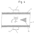
- FIG. 6 is a schematic drawing to show the flow quantity measurement principle of the flow sensor according to the first embodiment of the invention.
- arrow F indicates a flow of fluid in the through water pipe line 10.
- a column PO for causing fluid to generate a Karman vortex is provided in the through water pipe line 10.
- the transmitter 111 is attached to the outer peripheral surface of the through water pipe line 10 downstream from the column PO in the through water pipe line 10
- the receiver 112 is attached to the outer peripheral surface of the through water pipe line 10 so as to be opposed to the transmitter 111.
- the transmitter 111 transmits an ultrasonic wave.
- the receiver 112 opposed to the transmitter 111 with the through water pipe line 10 between receives the ultrasonic wave transmitted through the through water pipe line 10 and the inside of the through water pipe line 10.
- the fluid flowing through the through water pipe line 10 generates a Karman vortex responsive to the flow quantity of the fluid in the presence of the column PO (arrows CU). Accordingly, the propagation time of the ultrasonic wave propagating in the fluid changes and therefore the flow quantity of the fluid flowing through the through water pipe line 10 is calculated based on the difference between the transmission point in time of the ultrasonic wave transmitted by the transmitter 111 and the reception point in time of the ultrasonic wave received by the receiver 112.
- FIG. 7 is an exploded perspective view of the cabinet of the flow sensor according to the first embodiment of the invention.
- the cabinet 30 has end faces 30a and 30b, side faces 30c and 30d, and a bottom face 30e.
- the through water pipe line 10 is provided so as to pierce the side faces 30c and 30d.
- the transmitter 111 and the receiver 112 are attached to the outer peripheral surface of the through water pipe line 10 with the through water pipe line 10 between.
- a press member 32 is made up of a pair of press parts 32a and 32b and a flat part 32c.
- the pair of press parts 32a and 32b is formed integrally with both ends of the flat part 32c angular U-shaped in cross section so as to be opposed to each other.
- the press part 32a is formed with a notch shaped like a letter U.
- the press parts 32a and 32b of the press member 32 are inserted between the transmitter 111 and the receiver 112 and the end faces 30a and 30b of the cabinet 30. Accordingly, the transmitter 111 and the receiver 112 are pressed against the outer peripheral surface of the through water pipe line 10 by the press parts 32a and 32b of the press member 32. Consequently, the transmitter 111 and the receiver 112 are fixed in the cabinet 30.
- the conductors of the transmitter 111 and the receiver 112 are introduced through the notch of the press part 32a and the conductor taking-out part 31 of the cabinet 30 into the outside. In this state, the opening of the cabinet 30 is covered with the lid 33, so that the cabinet 30 can be hermetically sealed.
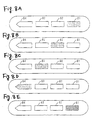
- FIGS. 8A to 8E are schematic drawings to describe the light emission patterns of the flow indicator of the flow sensor according to the first embodiment of the invention.
- the green LED 81G of the light emission section 81 goes on in green as shown in FIG. 8A; next, the light emission section 81 goes off and the light emission section 82 goes on in green as shown in FIG. 8B; subsequently the light emission section 82 goes off and the light emission section 83 goes on in green as shown in FIG. 8C; and further the light emission section 83 goes off and the light emission section 84 goes on in green as shown in FIG. 8D.
- This operation is repeated in the order of FIG. 8A to FIG. 8D.
- the light emission sections are turned on in order at the speed responsive to the detected flow quantity, so that the user can easily recognize the flow of the fluid from a distance.
- the display section can be miniaturized and the detection section can also be miniaturized.
- the limit emission operation of the flow indicator LU is performed based on the frequency of a Karman vortex as described above; for example, the frequency of a Karman vortex occurring in a flow sensor having a 1/2-inch bore is about 600 Hz at the maximum. If the limit emission operation is performed based on the frequency, it is too fast for human eyes to recognize the forward mode clearly. Then, 600-Hz pulse is divided by six 1/2 frequency dividers, whereby 9.4-Hz. pulse at the maximum can be provided. In this case, forward display is produced at natural speed for human eyes.
- the frequency dividing ratio can be determined appropriately by the bore of the flow sensor.
- the frequency dividing method can be realized by a logical circuit or microcomputer software.
- the light emission sections 81 to 84 of the flow indicator LU need not necessarily go on in green in order.
- the light emission sections 81 to 84 may produce level display of the detected flow quantity rather than going on in green in order. Specifically, as many light emission sections as the number responsive to the flow quantity are turned on.
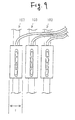
- FIG. 9 is a drawing to show an application example of the detection sections of the flow sensor according to the first embodiment of the invention.
- the detection section of the flow sensor according to the embodiment has the small thick in the predetermined direction (t in FIG. 9) as shown in FIG. 5A, so that a plurality of detection sections 100 can be brought close into each other, as shown in FIG. 9.
- the flow sensor according to the embodiment is formed of resin fluoride, etc. Therefore, the flow sensor is used suitably for a manufacturing line, etc., where fluid of chemicals, etc., flows.
- the flow sensor is also suited for measurement of the flow quantity of a fluid requiring cleanness.
- a flow sensor according to a second embodiment of the invention has a similar configuration and similar operation to those of the flow sensor according to the first embodiment except for the following points:
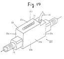
- FIG. 10 is an external perspective view of a detecticn section of the flow sensor according to the second embodiment of the invention.
- the detection section 500 of the flow sensor includes a casing 20.
- the casing 20 has an upper face 20a, a lower face 20b, an end face 20c, an end face 20d, a side face 20e, and a side face 20f.
- a through water pipe line 10 molded of the same material as the casing 20 is projected from the end faces 20c and 20d of the casing 20.
- a fluid flows in the direction indicated by the arrow through the through water pipe line 10.
- a cable 40 for transmitting the detected flow quantity value to a main unit section 200 is connected to the rear end part of the casing 20.
- a flow indicator LU similar to that in the first embodiment is provided on the upper face 20a of the casing 20.
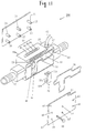
- FIG. 11 is an exploded perspective view of the detection section of the flow sensor according to the second embodiment of the invention.
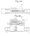
- FIG. 12A is a plan view of the detection section of the flow sensor according to the second embodiment of the invention and
- FIG. 12B is an exploded side view of the detection section of the flow sensor according to the second embodiment of the invention.
- the detection section 500 is made up of casing members 21, 22, and 23, the through water pipe line 10, two circuit boards W, packing PK, a plurality of screws 50, and a press member 32.
- the through water pipe line 10 is formed integrally with the casing member 22.
- the casing members 21, 22, and 23 are combined into the casing 20 in FIG. 10.
- the casing member 22 has a circuit/sensor housing area AS in an internal portion.
- the circuit/sensor housing area AS is surrounded by the upper face 20a of the casing member 22 and a partition plane SI.
- the two circuit boards W are installed so as to overlap each other in an upper portion of the circuit/sensor housing area AS.
- Installed on the circuit boards W are a high frequency signal oscillator 120, a high frequency signal amplifier 130, a phase comparator 140, a low frequency amplifier 150, a comparator 160, a frequency divider 170, a decoder 180, a signal level determination unit 190, and the above-mentioned flow indicator LU.
- a transmitter 111 and a receiver 112 are attached to the through water pipe line 10 as in the cabinet 30 of the detection section 100 according to the first embodiment.
- the transmitter 111 and the receiver 112 are housed in a lower portion of the circuit/sensor housing area AS by the press member 32.
- the press member 32 is made up of a pair of press parts 32a and 32b and a flat part 32c.
- the pair of press parts 32a and 32b is formed at both ends of the flat part 32c so as to be opposed to each other.
- the two circuit boards W are attached and the transmitter 111 and the receiver 112 are attached to the through water pipe line 10 by the press member 32.
- the casing member 22 is joined to the casing members 21 and 23 by the plurality of screws 50 via the packing PK on a seal face GS.
- the packing PK is mounted on the seal face GS, whereby the internal space of the circuit/sensor housing area AS is reliably hermetically scaled.
- the casing members 21, 22, and 23 are attached to each other by the plurality of screws 50 as follows:
- the screws 50 are screwed through threaded holes a1 to a8 of the casing member 22 into threaded holes C1 to C8 of the casing members 21 and 22, whereby the casing members 21, 22, and 23 are attached to each other.
- the casing members 21, 22, and 23 are attached by the plurality of screws 50, whereby the casing 20 can be easily made waterproof.
- the casing members 21, 22, and 23 may be attached not only by the plurality of screws 50, but also with an adhesive, etc.
- the detection section 500 of the flow sensor according to the embodiment can be molded of the same material in one piece and can be easily manufactured and cost reduction is made possible.
- thickness t of the detection section 500 of the flow sensor in one direction of the detection section 500 also lessens.
- the thickness t is, for example, 22.5 mm.
- the flow indicator LU corresponds to the display section
- the light emission sections 81 to 84 correspond to the light emission sections
- the frequency divider 170 and the decoder 180 correspond to the control section
- the transmitter 111 and the receiver 112 correspond to the Karman vortex detection section
- the high frequency signal oscillator 120 corresponds to the pulse generation means.
- the through water pipe line 10 corresponds to the pipe line
- the column PO corresponds to the vortex generation member
- the transmitter 111 and the receiver 112 correspond to the pair of ultrasonic devices
- the pair of press parts 32a and 32b corresponds to the pair of press parts
- the flat part 32c corresponds to the joint part
- the press member 32 corresponds to the press member.
- circuit/sensor housing area AS corresponds to the housing space
- the short side of the side face 20e, 20f of the detection section 100, 500 corresponds to the width of the first length
- the short side of the top face 20a, 20b of the detection section 100, 500 corresponds to the thickness of the second length
- the cabinet 30 corresponds to the hermetic seal space.
Abstract
Description
- This invention relates to a flow sensor for detecting the flow quantity of a fluid.
- Hitherto, various flow sensors have been used to detect the flow quantity of a fluid. For example, an ultrasonic vortex flow sensor detects ultrasonically in a noncontact manner a Karman vortex occurring regularly downstream from a vertex generation pole placed in a flow. The ultrasonic vortex flow sensor can ultrasonically detect change in Karman vortex, thereby detecting the flow quantity with high accuracy in a wide flow quantity range. (For example, refer to JP-A-4-77620 and JP-A-8-304142)
- Such flow sensors include an integral-type flow sensor and a separate flow sensor. The integral-type flow sensor, which has a flow quantity detection part and a flow quantity display part in one piece, becomes large. On the other hand, the separate flow sensor is made up of a detection section for detecting the flow quantity and a display section for displaying the value of the detected flow quantity. Generally, in the separate flow sensor, the detection section does not have a display section and thus can be miniaturized.
- However, to install the detection section, the user cannot check whether or not the flow quantity exists and cannot check whether or not the flow sensor operates normally either.
- FIG. 13 is an external perspective view of the detection section of the flow sensor in the related art, and FIG. 14 is an exploded perspective view of the detection section of the flow sensor in the related art.
- As shown in FIG. 13, a
detection section 900 has acasing 940 shaped like a rectangular parallelepiped and is provided with a throughwater pipe line 910 so as to pierce opposed sides of thecasing 940. Acircuit board 950 is placed above the throughwater pipe line 910. - As shown in FIG. 14, a cylindrical
element storage part 920 is provided on both sides of the outer peripheral surface of the throughwater pipe line 910, and atransmitter 911 and areceiver 912 are inserted into theelement storage parts 920. Eachelement storage part 920 is closed by apress member 930 having aconvex part 9a at the center. Accordingly, theconvex parts 9a of thepress members 930 press thetransmitter 911 and thereceiver 912 against the outer peripheral surface of the throughwater pipe line 910. A taking-cut pipe 970 of a conductor KB of thetransmitter 911 and thereceiver 912 of the throughwater pipe line 910 is provided in the direction crossing theelement storage parts 920. - Thus, the
press members 930 each having theconvex part 9a at the center press thetransmitter 911 and thereceiver 912 against the outer peripheral surface of the throughwater pipe line 910, so that the size of thedetection section 900 of the flow sensor in the related art becomes large in the direction in which thetransmitter 911 and thereceiver 912 are aligned and the size also becomes large.in the direction crossing the direction in which thetransmitter 911 and thereceiver 912 are aligned. Since such a structure is housed in thecasing 940, thedetection section 900 is upsized as a whole. Recently, making slim thedetection section 900 has been desired. - This and related problems are solved by the flow sensor according to claim 1.
- Improvements and special aspects of the invention are disclosed in the description, the figures and the dependent claims.
- It is an object of the invention to provide a flow sensor for enabling the user to easily check the detection state of the flow quantity on a detection section.
- It is another object of the invention to provide a flow sensor for enabling the user to easily check the detection state of the - flow quantity on a detection section that can be miniaturized and made slim.
- According to the invention, there isprovideda f lowsensor including a detection section for detecting a flow quantity of a fluid, the detection section having a display section for displaying information based on the detected flow quantity; and a main unit section being provided as a separate body from the detection section for displaying the flow quantity detected by the detection section.
- In one embodiment of the invention, the detection section detects the flow quantity of a fluid. The detected flow quantity is displayed on the main unit section provided as a separate body from the detection section. The information based on the detected flow quantity is displayed on the display section of the detection section.
- In this case, the detection section is provided with the display section for displaying the information based on the flow quantity, thus enabling the user to easily check the detection state of the flow quantity on the detection section.
- The display section may includes a plurality of light emission sections; and a control section for turning on the plurality of light emission sections in order at speed responsive to the detected flow quantity.
- In this case, the plurality of light emission sections are turned on in order at the speed responsive to the detected flow quantity, so that the user can easily recognize the flow of the fluid from a distance. The display section can be miniaturized and the detection section can also be miniaturized.
- The detection section may further include a Karman vortex detection section for ultrasonically detecting change in a Karman vortex of a fluid; and a pulse signal generation section for generating a pulse signal corresponding to the change in the Karman vortex detected by the Karman vortex detection section, and the control section may turn on the plurality of light emission sections in order based on the pulse signal generated by the pulse signal generation section.
- In this case, change in a Karman vortex of a fluid is ultrasonically detected and a pulse signal corresponding to the detected change in the Karman vortex is generated. The plurality of light emission sections are tuned on in order based on the pulse signal.
- Accordingly, the plurality of light emission sections are turned on in order at the speed corresponding to the flow quantity of the fluid, so that the user can visually recognize the flow of the fluid from a distance.
- The display section may display a level responsive to the detected flow quantity. In this case, since the level responsive to the detected flow quantity is displayed, the user can visually recognize the flow of the fluid from a distance.
- The detection section may include a pipe line through which a fluid passes; a vortex generation member being provided in the pipe line for generating a Karman vortex; a pair of ultrasonic devices being placed on an outer peripheral surface of the pipe line so as to be opposed to each other with the pipe line between; and a press member having a pair of press parts for pressing the pair of ultrasonic devices against the pipe line and a joint part for joining the pair of press parts.
- In this case, the pair of ultrasonic devices is placed on the outer peripheral surface of the pipe line so as to be opposed to each other with the pipe line between, and is pressed against the pipe line by the pair of press parts joined by the joint part of the press member.
- The detection section may include a casing having a width of a first length and a thickness of a second length smaller than the first length, and the pair of ultrasonic devices may be placed in the casing so as to be arranged in a width direction.
- In this case, the pair of ultrasonic devices is provided in the casing so as to be arranged in the width direction, so that the detection section can be miniaturized and made slim.
- The case may include a housing space for housing a circuit board connected to the display section provided so as to be adjacent to one of the ultrasonic devices in the width direction.
- In this case, the housing space for housing the circuit board is provided so as to be adjacent to one of the ultrasonic devices in the width direction in the casing, so that the detection section can be miniaturized and made slim.
- The case may include a hermetic seal space for hermetically sealing the pair of ultrasonic devices and a part of the pipe line. In this case, the hermetic seal space for hermetically sealing the pair of ultrasonic devices and a part of the pipe line is provided in the casing, so that the pair of ultrasonic devices and a part of the pipe line can be prevented from being contaminated by dust.
- The housing space and the hermetic seal space may be put into one piece. In this case, the housing space and the hermetic seal space are put into one piece, whereby the pair of ultrasonic devices, a part of the pipe line, and the circuit board can be prevented from being contaminated by dust.
- In particular, preferably, a transmitter transmits an ultrasonic wave, a receiver receives the ultrasonic wave from the transmitter, an output signal of the receiver is amplified, aphase comparator outputs a voltage corresponding to the phase difference based on a high frequency signal generatedby ahigh frequency signal oscillator and an output signal of a high frequency signal amplifier. Further, preferably, a low frequency amplifier amplifies the output voltage of the phase comparator, a comparator compares the output signal of the low frequency amplifier with a reference voltage and outputs a pulse indicating the comparison result, a frequency divider divides the output pulse, a decoder decodes the output signal of the frequency divider for turning on light emission sections of a flow indicator in green in order.
- In the accompanying drawings, several embodiments of the invention are disclosed:
- FIG. I is a schematic drawing to show the configuration of a flow sensor according to a first embodiment of the invention;
- FIG. 2 is a block diagram to show the configuration of the flow sensor according to the first embodiment of the invention;
- FIGS. 3A and 3B are external perspective views of a detection section of the flow sensor according to the first embodiment of the invention;
- FIG. 4 is an exploded perspective view of the detection section of the flow sensor according to the first embodiment of the invention;
- FIG. 5A is a plan view of the detection section of the flow sensor according to the first embodiment of the invention and FIG. 5B is an exploded side view of the detection section of the flow sensor according to the first embodiment of the invention;
- FIG. 6 is a schematic drawing to show the flow quantity measurement principle of the flow sensor according to the first embodiment of the invention;
- FIG. 7 is an exploded perspective view of a cabinet of the flow sensor according to the first embodiment of the invention;
- FIGS. 8A to 8E are schematic drawings to describe light emission patterns of a flow indicator of the flow sensor according to the first embodiment of the invention;
- FIG. 9 is a drawing to show an application example of the detection sections of the flow sensor according to the first embodiment of the invention;
- FIG. 10 is an external perspective view of a detection section of a flow sensor according to a second embodiment of the invention;
- FIG. 11 is an exploded perspective view of the detection section of the flow sensor according to the second embodiment of the invention;
- FIG. 12A is a plan view of the detection section of the flow sensor according to the second embodiment of the invention and FIG. 12B is an exploded side view of the detection section of the flow sensor according to the second embodiment of the invention;
- FIG. 13 is an external perspective view of a detection section of a flow sensor in a related art; and
- FIG. 14 is an exploded perspective view of the detection section of the flow sensor in the related art.
-
- Referring now to the accompanying drawings (FIGS. 1 to 12), there are shown flow sensors according to first and second embodiments of the invention.
- FIG. 1 is a schematic drawing to show the configuration of a flow sensor according to a first embodiment of the invention.
- In FIG. 1, the flow sensor is made up of a detection section (sensor head) 100 and a main unit section (sensor main unit section) 200. The
detection section 100 is connected to themain unit section 200 by a cable. Themain unit section 200 has adisplay section 230. - FIG. 2 is a block diagram to show the configuration of the flow sensor according to the first embodiment of the invention. As shown in FIG. 2, the flow sensor is made up of the
detection section 100 and themain unit section 200. - The
detection section 100 includes atransmitter 111, areceiver 112, a highfrequency signal oscillator 120, a highfrequency signal amplifier 130, aphase comparator 140, alow frequency amplifier 150, acomparator 160, afrequency divider 170, adecoder 180, a signal level determination unit 190, and a flow indicator LU. This flow indicator LU includeslight emission sections 81 to 84. Thelight emission section 81 is made up of a red LED (light emitting diode) 81R and agreen LED 81G. Each of thelight emission sections 82 to 84 has a green LED. Thetransmitter 111 and thereceiver 112 are implemented as ultrasonic devices, for example. - The
main unit section 200 includes afrequency measurement device 210, acomputing unit 220, adisplay section 230, acontrol output section 240, and ananalog output section 250. Thefrequency measurement device 210 and thecomputing unit 220 are implemented as a CPU (central processing unit), for example. - The high
frequency signal oscillator 120 generates a high frequency signal and gives the high frequency signal to thetransmitter 111, which then transmits an ultrasonic wave. Thereceiver 112 receives the ultrasonic wave from thetransmitter 111. In this case, the frequency of a Karman vortex occurring on a fluid changes due to the flow quantity of the fluid. The ultrasonic wave propagation time changes in proportion to the frequency of the Karman vortex. Therefore, change in the ultrasonic wave propagation time from thetransmitter 111 to thereceiver 112 is detected, whereby the flow quantity can be detected. - The high
frequency signal amplifier 130 amplifies an output signal of thereceiver 112. Thephase comparator 140 makes a phase comparison between the high frequency signal generated by the highfrequency signal oscillator 120 and the output signal of the highfrequency signal amplifier 130 and outputs a voltage corresponding to the phase difference. Thelow frequency amplifier 150 amplifies the output voltage of thephase comparator 140. - The
comparator 160 compares the output signal of thelow frequency amplifier 150 with a reference voltage and outputs a pulse indicating the comparison result. Thefrequency divider 170 divides the pulse output from thecomparator 160. Thedecoder 180, which is implemented as a shift register, decodes the output signal of thefrequency divider 170, thereby turning on thelight emission sections 81 to 84 of the flow indicator LU in green in order. In this case, the speed at which thelight emission sections 81 to 84 of the flow indicator LU are turned on in order chances in response to the flow quantity. The state in which thelight emission sections 81 to 84 of the flow indicator LU are turned on is described later in detail. - The signal level determination unit 190 determines whether or not the level of the output signal of the high
frequency signal amplifier 130 falls below a predetermined value. If the level of the output signal falls below the predetermined value, the signal level determination unit 190 turns on thered LED 81R of thelight emission section 81 and prohibits thedecoder 180 from turning on thegreen LED 81G of thelight emission section 81 and thelight emission sections 82 to 84 and further gives an alarm signal to thecomputing unit 220. Accordingly, thecomputing unit 220 can recognize that the reception level falls. If the through water pipe line through which a fluid flows is not filled with a fluid or if a bubble exists in a fluid, the reception level of thereceiver 112 falls and the accurate flow quantity value cannot be detected. In this case, the signal level determination unit 190 outputs an alarm signal. - If the signal level determination unit 190 gives an alarm signal to the
computing unit 220, thecomputing unit 220 controls thedisplay section 230, thecontrol output section 240, and theanalog output section 250 based on the given alarm signal. - If the given alarm signal is on (for example, high), the
computing unit 220 causes thedisplay section 230 to display an alarm and performs processing with a digital filter. For example, if the alarm signal is on, thecomputing unit 220 causes thedisplay section 230 to display the flow quantity value applied before the alarm signal is turned on as many times as the preset number of times or calculates moving average of the flow quantity values as many times as the preset number of times and causes thedisplay section 230 to display the moving average. If the alarm signal is on, thecontrol output section 240 turns on or off first output and second output using the flow quantity value applied before the alarm signal is turned on as many times as the preset number of times or turns on or off first output and second output based on the moving average of the flow quantity values as many times as the preset number of times. Further, theanalog output section 250 outputs an analog alarm signal. - Thus, if the alarm signal is on, the
computing unit 220 performs different processing from that if the alarm signal is off (for example, low), thereby performing processing based on the flow quantity value close to the accurate flow quantity value. Accordingly, processing based on an erroneous flow quantity value when the alarm signal is on can be prevented from being performed without decreasing the response speed when the alarm signal is off (in the normal mode). - The
frequency measurement device 210 measures the frequency of the pulse output from thecomparator 160. Thecomputing unit 220 converts the frequency measured by thefrequency measurement device 210 into a flow quantity and controls thedisplay section 230, thecontrol output section 240, and theanalog output section 250 based on the flow quantity value. - The
control output section 240 turns on or off first output and second output based on the flow quantity value. Theanalog output section 250 outputs an analog signal indicating the flow quantity value. - FIGS. 3A and 3B are external perspective views of the detection section of the flow sensor according to the first embodiment of the invention; FIG. 3A shows the detection section from one side and FIG. 3B shows the detection section from an opposite side.
- In FIG. 3, the
detection section 100 of the flow sensor includes acasing 20. Thecasing 20 has anupper face 20a, alower face 20b, anend face 20c, anend face 20d, aside face 20e, and aside face 20f. - A through
water pipe line 10 made of a resin such as resin fluoride is provided so as to pierce the end faces 20c and 20d of thecasing 20. A fluid flows in the direction indicated by the arrow through the throughwater pipe line 10. Acable 40 for transmitting the detected flow quantity value to themain unit section 200 is connected to theend face 20c of thecasing 20. Further, the above-described flow indicator LU is provided on theupper face 20a of thecasing 20. - As shown in FIG. 3B, the
casing 20 is formed on theside face 20f with arectangular notch part 20K. In thenotch part 20K, alid 33 of acabinet 30 integral with the throughwater pipe line 10 is flush with theside face 20f of thecasing 20, forming a part of thecasing 20. - FIG. 4 is an exploded perspective view of the detection section of the flow sensor according to the first embodiment of the invention. FIG. 5A is a plan view of the detection section of the flow sensor according to the first embodiment of the invention and FIG. 5B is an exploded side view of the detection section of the flow sensor according to the first embodiment of the invention.
- In FIG. 4, the
detection section 100 is made up ofcasing members water pipe line 10, two circuit boards W, packing PK, and a plurality ofscrews 50. The throughwater pipe line 10 is provided so as to pierce thecabinet 30 and is integral with thecabinet 30. Thecasing members casing 20 in FIG. 3. - The casing
member 21 has a circuit housing area AR in an internal upper portion. The circuit housing area AR is surrounded by theupper face 20a of thecasing member 21 and a partition plane SI. The two circuit boards W are installed so as to overlap each other in the circuit housing area AR. - Installed on the circuit boards W are the high
frequency signal oscillator 120, the highfrequency signal amplifier 130, thephase comparator 140, thelow frequency amplifier 150, thecomparator 160, thefrequency divider 170, thedecoder 180, the signal level determination unit 190, and the flow indicator LU described above. - Four holes are made in the
upper face 20a of thecasing member 21. Thelight emission sections 81 to 84 are placed on the circuit boards W in the circuit housing area AR corresponding to the four holes of thecasing member 21. - To assemble the
detection section 100, the throughwater pipe line 10 is attached to the inner lower side of thecasing member 21. Thecabinet 30 is integral with the throughwater pipe line 10 as described above and is fitted into thenotch part 20K of the casing member 21 (see FIG. 3B). - A conductor taking-out
part 31 is provided on anend face 30a of thecabinet 30. A conductor introduction hole KH is made in the partition plane SI of thecasing member 21. To attach thecabinet 30 to thecasing member 21, the conductor taking-outpart 31 of thecabinet 30 is fitted into the conductor introduction hole KH. Accordingly, conductors of thetransmitter 111 and thereceiver 112 implemented as ultrasonic devices (described later) in thecabinet 30 are introduced through the conductor taking-outpart 31 and the conductor introduction hole KH into the circuit boards W in the circuit housing area AR. - A seal member (not shown) is previously mounted on the conductor introduction hole KH. Therefore, the conductor taking-out
part 31 and the conductor introduction hole KH are fitted into each other, whereby the inside of thecabinet 30 and the circuit housing area AR communicate with each other and become a hermetically sealed space. - As shown in FIG. 4, the casing
member 21 to which the two circuit boards W and the throughwater pipe line 10 are attached is joined to thecasing member 22 by the plurality ofscrews 50 via the packing PK on a seal face GS. The packing PK is mounted on the seal face GS, whereby the internal space of the circuit housing area AR is reliably hermetically sealed. - In FIG. 4, the
casing members screws 50 as follows : Thescrews 50 are screwed through threaded holes a1 to a9 of thecasing member 22 into threaded holes c1 to c8 of thecasing member 21, whereby thecasing member 21 is attached to thecasing member 22. The throughwater pipe line 10 is formed with screw introduction holes b4 to b8. To attach thecasing members screws 50 passing through the threaded holes a4 to a8 of thecasing member 22 pass through the screw introduction holes b4 to b8. - Thus, the
casing members screws 50, whereby thecasing 20 can be easily made waterproof. - In the embodiment, the
casing members screws 50, but also with an adhesive, etc. - The
casing members detection section 100 of the flow sensor in one direction of thedetection section 100 is narrowed, as shown in FIG. 5A. The thickness t is, for example, 20.0 mm. - The measurement principle of the flow quantity in the
cabinet 30 will be discussed with FIG. 6. FIG. 6 is a schematic drawing to show the flow quantity measurement principle of the flow sensor according to the first embodiment of the invention. In FIG. 6, arrow F indicates a flow of fluid in the throughwater pipe line 10. A column PO for causing fluid to generate a Karman vortex is provided in the throughwater pipe line 10. - In the
cabinet 30, thetransmitter 111 is attached to the outer peripheral surface of the throughwater pipe line 10 downstream from the column PO in the throughwater pipe line 10, and thereceiver 112 is attached to the outer peripheral surface of the throughwater pipe line 10 so as to be opposed to thetransmitter 111. - To measure the flaw quantity of the fluid flowing through the through
water pipe line 10, thetransmitter 111 transmits an ultrasonic wave. In contrast, thereceiver 112 opposed to thetransmitter 111 with the throughwater pipe line 10 between receives the ultrasonic wave transmitted through the throughwater pipe line 10 and the inside of the throughwater pipe line 10. - The fluid flowing through the through
water pipe line 10 generates a Karman vortex responsive to the flow quantity of the fluid in the presence of the column PO (arrows CU). Accordingly, the propagation time of the ultrasonic wave propagating in the fluid changes and therefore the flow quantity of the fluid flowing through the throughwater pipe line 10 is calculated based on the difference between the transmission point in time of the ultrasonic wave transmitted by thetransmitter 111 and the reception point in time of the ultrasonic wave received by thereceiver 112. - The structure of the
cabinet 30 will be discussed with FIG. 7. FIG. 7 is an exploded perspective view of the cabinet of the flow sensor according to the first embodiment of the invention. - In FIG. 7, the
cabinet 30 has end faces 30a and 30b, side faces 30c and 30d, and abottom face 30e. The throughwater pipe line 10 is provided so as to pierce the side faces 30c and 30d. In thecabinet 30, thetransmitter 111 and thereceiver 112 are attached to the outer peripheral surface of the throughwater pipe line 10 with the throughwater pipe line 10 between. - A
press member 32 is made up of a pair ofpress parts 32a and 32b and a flat part 32c. The pair ofpress parts 32a and 32b is formed integrally with both ends of the flat part 32c angular U-shaped in cross section so as to be opposed to each other. The press part 32a is formed with a notch shaped like a letter U. Thepress parts 32a and 32b of thepress member 32 are inserted between thetransmitter 111 and thereceiver 112 and the end faces 30a and 30b of thecabinet 30. Accordingly, thetransmitter 111 and thereceiver 112 are pressed against the outer peripheral surface of the throughwater pipe line 10 by thepress parts 32a and 32b of thepress member 32. Consequently, thetransmitter 111 and thereceiver 112 are fixed in thecabinet 30. - The conductors of the
transmitter 111 and thereceiver 112 are introduced through the notch of the press part 32a and the conductor taking-outpart 31 of thecabinet 30 into the outside. In this state, the opening of thecabinet 30 is covered with thelid 33, so that thecabinet 30 can be hermetically sealed. - Subsequently, light emission patterns of the
light emission sections 81 to 84 of the flow indicator LU will be discussed in detail with FIG. 8. FIGS. 8A to 8E are schematic drawings to describe the light emission patterns of the flow indicator of the flow sensor according to the first embodiment of the invention. - When the flow quantity in the through
water pipe line 10 is measured, if the fluid in the throughwater pipe line 10 flows, thelight emission sections 81 to 84 of the flow indicator LU blink in green in order. - For example, first the
green LED 81G of thelight emission section 81 goes on in green as shown in FIG. 8A; next, thelight emission section 81 goes off and thelight emission section 82 goes on in green as shown in FIG. 8B; subsequently thelight emission section 82 goes off and thelight emission section 83 goes on in green as shown in FIG. 8C; and further thelight emission section 83 goes off and thelight emission section 84 goes on in green as shown in FIG. 8D. This operation is repeated in the order of FIG. 8A to FIG. 8D. - In this case, the light emission sections are turned on in order at the speed responsive to the detected flow quantity, so that the user can easily recognize the flow of the fluid from a distance. The display section can be miniaturized and the detection section can also be miniaturized.
- On the other hand, when the flow quantity in the through
water pipe line 10 is measured, if there is no fluid in the throughwater pipe line 10 or if the fluid contains a large number of bubbles or the like, thelight emission section 81 of the flow indicator LU goes on in red as shown in FIG. 8E. - Here, assume that the
light emission sections 81 to 84 of the flow indicator LU blink in order in a specific directicn (for example, forward). In the embodiment, the limit emission operation of the flow indicator LU is performed based on the frequency of a Karman vortex as described above; for example, the frequency of a Karman vortex occurring in a flow sensor having a 1/2-inch bore is about 600 Hz at the maximum. If the limit emission operation is performed based on the frequency, it is too fast for human eyes to recognize the forward mode clearly. Then, 600-Hz pulse is divided by six 1/2 frequency dividers, whereby 9.4-Hz. pulse at the maximum can be provided. In this case, forward display is produced at natural speed for human eyes. - Thus, the frequency dividing ratio can be determined appropriately by the bore of the flow sensor. The frequency dividing method can be realized by a logical circuit or microcomputer software.
- In the embodiment, the
light emission sections 81 to 84 of the flow indicator LU need not necessarily go on in green in order. For example, thelight emission sections 81 to 84 may produce level display of the detected flow quantity rather than going on in green in order. Specifically, as many light emission sections as the number responsive to the flow quantity are turned on. - FIG. 9 is a drawing to show an application example of the detection sections of the flow sensor according to the first embodiment of the invention. The detection section of the flow sensor according to the embodiment has the small thick in the predetermined direction (t in FIG. 9) as shown in FIG. 5A, so that a plurality of
detection sections 100 can be brought close into each other, as shown in FIG. 9. - The flow sensor according to the embodiment is formed of resin fluoride, etc. Therefore, the flow sensor is used suitably for a manufacturing line, etc., where fluid of chemicals, etc., flows. The flow sensor is also suited for measurement of the flow quantity of a fluid requiring cleanness.
- A flow sensor according to a second embodiment of the invention has a similar configuration and similar operation to those of the flow sensor according to the first embodiment except for the following points:
- FIG. 10 is an external perspective view of a detecticn section of the flow sensor according to the second embodiment of the invention.
- In FIG. 10, the
detection section 500 of the flow sensor includes acasing 20. Thecasing 20 has anupper face 20a, alower face 20b, anend face 20c, anend face 20d, aside face 20e, and aside face 20f. - A through
water pipe line 10 molded of the same material as thecasing 20 is projected from the end faces 20c and 20d of thecasing 20. A fluid flows in the direction indicated by the arrow through the throughwater pipe line 10. Acable 40 for transmitting the detected flow quantity value to amain unit section 200 is connected to the rear end part of thecasing 20. Further, a flow indicator LU similar to that in the first embodiment is provided on theupper face 20a of thecasing 20. - FIG. 11 is an exploded perspective view of the detection section of the flow sensor according to the second embodiment of the invention. FIG. 12A is a plan view of the detection section of the flow sensor according to the second embodiment of the invention and FIG. 12B is an exploded side view of the detection section of the flow sensor according to the second embodiment of the invention.
- In FIG. 11, the
detection section 500 is made up ofcasing members water pipe line 10, two circuit boards W, packing PK, a plurality ofscrews 50, and apress member 32. The throughwater pipe line 10 is formed integrally with thecasing member 22. Thecasing members casing 20 in FIG. 10. - The casing
member 22 has a circuit/sensor housing area AS in an internal portion. The circuit/sensor housing area AS is surrounded by theupper face 20a of thecasing member 22 and a partition plane SI. The two circuit boards W are installed so as to overlap each other in an upper portion of the circuit/sensor housing area AS. - Installed on the circuit boards W are a high
frequency signal oscillator 120, a highfrequency signal amplifier 130, aphase comparator 140, alow frequency amplifier 150, acomparator 160, afrequency divider 170, adecoder 180, a signal level determination unit 190, and the above-mentioned flow indicator LU. - In a lower portion of the
casing member 22, atransmitter 111 and areceiver 112 are attached to the throughwater pipe line 10 as in thecabinet 30 of thedetection section 100 according to the first embodiment. When thetransmitter 111 and thereceiver 112 are attached to the throughwater pipe line 10, they are housed in a lower portion of the circuit/sensor housing area AS by thepress member 32. Thepress member 32 is made up of a pair ofpress parts 32a and 32b and a flat part 32c. The pair ofpress parts 32a and 32b is formed at both ends of the flat part 32c so as to be opposed to each other. - Four holes are made in the
upper face 20a of thecasing member 21.Light emission sections 81 to 84 are placed on the circuit boards W in the circuit/sensor housing area AS corresponding to the four holes of thecasing member 21. - As shown in FIG. 11, the two circuit boards W are attached and the
transmitter 111 and thereceiver 112 are attached to the throughwater pipe line 10 by thepress member 32. The casingmember 22 is joined to thecasing members screws 50 via the packing PK on a seal face GS. The packing PK is mounted on the seal face GS, whereby the internal space of the circuit/sensor housing area AS is reliably hermetically scaled. - In FIG. 11, the
casing members screws 50 as follows: Thescrews 50 are screwed through threaded holes a1 to a8 of thecasing member 22 into threaded holes C1 to C8 of thecasing members casing members - Thus, the
casing members screws 50, whereby thecasing 20 can be easily made waterproof. - In the embodiment, the
casing members screws 50, but also with an adhesive, etc. - The
detection section 500 of the flow sensor according to the embodiment can be molded of the same material in one piece and can be easily manufactured and cost reduction is made possible. In the structure of thedetection section 500 of the flow sensor according to the embodiment, thickness t of thedetection section 500 of the flow sensor in one direction of the detection section 500 (FIG. 12) also lessens. The thickness t is, for example, 22.5 mm. - In the first and second embodiments described above, the flow indicator LU corresponds to the display section, the
light emission sections 81 to 84 correspond to the light emission sections, thefrequency divider 170 and thedecoder 180 correspond to the control section, thetransmitter 111 and thereceiver 112 correspond to the Karman vortex detection section, and the highfrequency signal oscillator 120 corresponds to the pulse generation means. The throughwater pipe line 10 corresponds to the pipe line, the column PO corresponds to the vortex generation member, thetransmitter 111 and thereceiver 112 correspond to the pair of ultrasonic devices, the pair ofpress parts 32a and 32b corresponds to the pair of press parts, the flat part 32c corresponds to the joint part, and thepress member 32 corresponds to the press member. - Further, the circuit/sensor housing area AS corresponds to the housing space, the short side of the
side face detection section top face detection section cabinet 30 corresponds to the hermetic seal space.
Claims (9)
- A flow sensor comprising:a detection section for detecting a flow quantity of a fluid, said detection section having a display section for displaying information based on the detected flow quantity; anda main unit section being provided as a separate body from said detection section for displaying the flow quantity detected by said detection section.
- The flow sensor as claimed in claim 1 wherein the display section includes:a plurality of light emission sections; anda control section for turning on the plurality of light emission sections in order at speed responsive to the detected flow quantity.
- The flow sensor as claimed in claim 2 wherein said detection section further includes:wherein the control section turns on the plurality of light emission sections in order based on the pulse signal generated by the pulse signal generation section.a Karman vortex detection section for ultrasonically detecting change in a Karman vortex of a fluid; anda pulse signal generation section for generating a pulse signal corresponding to the change in the Karman vortex detected by the Karman vortex detection section,
- The flow sensor according to any of the claims 1 to 3 wherein the display section displays a level responsive to the detected flow quantity.
- The flow sensor according to any of the claims 1 to 4 wherein said detection section comprises:a pipe line through which a fluid passes;a vortex generation member being provided in the pipe line for generating a Karman vortex;a pair of ultrasonic devices being placed on an outer peripheral surface of the pipe line so as to be opposed.to each other with the pipe line between; anda press member having a pair of press parts for pressing the pair of ultrasonic devices against the pipe line and a joint part for joining the pair of press parts.
- The flow sensor as claimed in claim 5 wherein said detection section comprises a casing having a width of a first length and a thickness of a second length smaller than the first length, wherein
the pair of ultrasonic devices is placed in the casing so as to be arranged in a width direction. - The flow sensor as claimed in claim 6 wherein the case includes a housing space for housing a circuit board for implementing the display section provided so as to be adjacent to one of the ultrasonic devices in the width direction.
- The flow sensor as claimed in claim 7 wherein the case includes a hermetic seal space for hermetically sealing the pair of ultrasonic devices and a part of the pipe line.
- The flow sensor as claimed in claim 8 wherein the housing space and the hermetic seal space are put into one piece.
Applications Claiming Priority (2)
| Application Number | Priority Date | Filing Date | Title |
|---|---|---|---|
| JP2003141917A JP4275990B2 (en) | 2003-05-20 | 2003-05-20 | Flow sensor |
| JP2003141917 | 2003-05-20 |
Publications (1)
| Publication Number | Publication Date |
|---|---|
| EP1482284A1 true EP1482284A1 (en) | 2004-12-01 |
Family
ID=33128182
Family Applications (1)
| Application Number | Title | Priority Date | Filing Date |
|---|---|---|---|
| EP20040011940 Withdrawn EP1482284A1 (en) | 2003-05-20 | 2004-05-19 | Flow sensor |
Country Status (3)
| Country | Link |
|---|---|
| US (1) | US7032461B2 (en) |
| EP (1) | EP1482284A1 (en) |
| JP (1) | JP4275990B2 (en) |
Cited By (7)
| Publication number | Priority date | Publication date | Assignee | Title |
|---|---|---|---|---|
| WO2007020375A1 (en) | 2005-08-13 | 2007-02-22 | Flownetix Limited | A method op construction for a low cost plastic ultrasonic water meter |
| EP2336732A1 (en) * | 2009-12-15 | 2011-06-22 | Kamstrup A/S | Consumption Meter with Flow Part and Housing Formed by a Monolithic Polymer Structure |
| WO2013081825A1 (en) | 2011-11-30 | 2013-06-06 | Rosemount Inc. | Turbine meter pre-scaling terminal block electronics |
| US8928137B2 (en) | 2013-05-15 | 2015-01-06 | Kamstrup A/S | Flow meter with ultrasound transducer directly connected to and fixed to measurement circuit board |
| US9658090B2 (en) | 2009-04-02 | 2017-05-23 | Kamstrup A/S | Ultrasonic flow meter unit having a fixing mechanism to fix the water-tight casing including a membrane to a housing including a measuring tube |
| EP3290875A1 (en) * | 2016-08-29 | 2018-03-07 | Apator Miitors ApS | Utility flow meter with display mode controller |
| US10921288B2 (en) | 2015-07-03 | 2021-02-16 | Kamstrup A/S | Fluid consumption meter with noise sensor |
Families Citing this family (13)
| Publication number | Priority date | Publication date | Assignee | Title |
|---|---|---|---|---|
| JP5160809B2 (en) * | 2007-05-08 | 2013-03-13 | Ckd株式会社 | Thermal flow meter |
| DE102008021930B4 (en) * | 2008-05-02 | 2011-05-05 | Rbs Wave Gmbh | Device for measuring the flow velocity in a flow tube |
| US8795225B2 (en) * | 2008-09-29 | 2014-08-05 | Covidien Lp | Fluid detection in an enteral feeding set |
| JP5268664B2 (en) * | 2009-01-14 | 2013-08-21 | トキコテクノ株式会社 | Ultrasonic vortex flowmeter |
| TWI400444B (en) * | 2010-08-13 | 2013-07-01 | Tatung Co | Ultrasonic phase-shift detection device |
| JP5548154B2 (en) * | 2011-03-04 | 2014-07-16 | アズビル株式会社 | How to check the pulse output of an accumulator and the accumulator |
| EP2568263B1 (en) * | 2011-09-12 | 2018-01-31 | Hydrosonic b.v. | Portable ultrasound flow measurement system |
| WO2016176521A1 (en) * | 2015-04-29 | 2016-11-03 | Covidien Lp | Detection of malfunction of flow monitoring system of flow control apparatus |
| CN107014482B (en) * | 2017-03-29 | 2020-05-01 | 西北工业大学 | Online monitoring device and method for vibration state |
| JP6876548B2 (en) | 2017-07-04 | 2021-05-26 | 株式会社キーエンス | Flowmeter |
| USD851524S1 (en) | 2018-01-18 | 2019-06-18 | Norgas Metering Technologies, Inc. | Ultrasonic flow meter |
| JP7142560B2 (en) * | 2018-12-21 | 2022-09-27 | クボタ空調株式会社 | Flow velocity measurement device, flow velocity measurement program, and flow velocity measurement method |
| DE102020108024A1 (en) | 2020-03-24 | 2021-09-30 | Ifm Electronic Gmbh | Display device for a flow meter in process automation technology |
Citations (5)
| Publication number | Priority date | Publication date | Assignee | Title |
|---|---|---|---|---|
| DE3000588A1 (en) * | 1980-01-09 | 1981-07-16 | Contis GmbH, 8000 München | Vehicle fuel consumption indicator with light band indicator - has slider indicator, clock circuit, flow transducer and LED array |
| EP0099712A2 (en) * | 1982-07-15 | 1984-02-01 | Jct Controls Limited | Flowmeters |
| EP0813041A1 (en) * | 1996-06-12 | 1997-12-17 | Asahi/America, Inc. | Ultrasonic vortex flowmeter having clamp-on housing |
| US5814735A (en) * | 1995-09-25 | 1998-09-29 | Smc Kabushiki Kaisha | Flow rate detector |
| EP1118841A2 (en) * | 2000-01-20 | 2001-07-25 | Ngk Spark Plug Co., Ltd | Vortex flowmeter for bidirectional flow |
Family Cites Families (6)
| Publication number | Priority date | Publication date | Assignee | Title |
|---|---|---|---|---|
| BE756043A (en) * | 1969-09-12 | 1971-02-15 | J Tec Ass Inc | METHOD AND APPARATUS FOR SONIC SPEED RECORDING |
| BE787873A (en) * | 1971-08-27 | 1973-02-23 | Westinghouse Electric Corp | FLOW METER |
| JP2798797B2 (en) | 1990-07-20 | 1998-09-17 | トキコ株式会社 | Flowmeter |
| JPH08271300A (en) | 1995-03-31 | 1996-10-18 | Tokico Ltd | Vortex flowmeter |
| JPH08304142A (en) | 1995-05-15 | 1996-11-22 | Tone Corp:Kk | Apparatus for flowmeter system |
| JP4942879B2 (en) | 2001-03-12 | 2012-05-30 | 株式会社キーエンス | Flow meter with display |
-
2003
- 2003-05-20 JP JP2003141917A patent/JP4275990B2/en not_active Expired - Fee Related
-
2004
- 2004-05-19 EP EP20040011940 patent/EP1482284A1/en not_active Withdrawn
- 2004-05-20 US US10/849,520 patent/US7032461B2/en not_active Expired - Fee Related
Patent Citations (5)
| Publication number | Priority date | Publication date | Assignee | Title |
|---|---|---|---|---|
| DE3000588A1 (en) * | 1980-01-09 | 1981-07-16 | Contis GmbH, 8000 München | Vehicle fuel consumption indicator with light band indicator - has slider indicator, clock circuit, flow transducer and LED array |
| EP0099712A2 (en) * | 1982-07-15 | 1984-02-01 | Jct Controls Limited | Flowmeters |
| US5814735A (en) * | 1995-09-25 | 1998-09-29 | Smc Kabushiki Kaisha | Flow rate detector |
| EP0813041A1 (en) * | 1996-06-12 | 1997-12-17 | Asahi/America, Inc. | Ultrasonic vortex flowmeter having clamp-on housing |
| EP1118841A2 (en) * | 2000-01-20 | 2001-07-25 | Ngk Spark Plug Co., Ltd | Vortex flowmeter for bidirectional flow |
Cited By (15)
| Publication number | Priority date | Publication date | Assignee | Title |
|---|---|---|---|---|
| WO2007020375A1 (en) | 2005-08-13 | 2007-02-22 | Flownetix Limited | A method op construction for a low cost plastic ultrasonic water meter |
| GB2429061B (en) * | 2005-08-13 | 2009-04-22 | Flownetix Ltd | A method of construction for a low cost plastic ultrasonic water meter |
| US7634950B2 (en) | 2005-08-13 | 2009-12-22 | Flownetix, Limited | Method of construction for a low cost plastic ultrasonic water meter |
| AU2006281287B2 (en) * | 2005-08-13 | 2011-05-12 | Flownetix Limited | A method of construction for a low cost plastic ultrasonic water meter |
| US9658090B2 (en) | 2009-04-02 | 2017-05-23 | Kamstrup A/S | Ultrasonic flow meter unit having a fixing mechanism to fix the water-tight casing including a membrane to a housing including a measuring tube |
| US8806957B2 (en) | 2009-12-15 | 2014-08-19 | Kamstrup A/S | Ultrasonic flow meter housing formed by a monolithic polymer structure |
| EP2336732A1 (en) * | 2009-12-15 | 2011-06-22 | Kamstrup A/S | Consumption Meter with Flow Part and Housing Formed by a Monolithic Polymer Structure |
| EP3211386A1 (en) * | 2009-12-15 | 2017-08-30 | Kamstrup A/S | Ultrasonic flow meter housing formed by a monolithic polymer structure |
| WO2013081825A1 (en) | 2011-11-30 | 2013-06-06 | Rosemount Inc. | Turbine meter pre-scaling terminal block electronics |
| EP2786483B1 (en) * | 2011-11-30 | 2019-01-09 | Rosemount Inc. | Turbine meter pre-scaling terminal block electronics |
| US8928137B2 (en) | 2013-05-15 | 2015-01-06 | Kamstrup A/S | Flow meter with ultrasound transducer directly connected to and fixed to measurement circuit board |
| US10921288B2 (en) | 2015-07-03 | 2021-02-16 | Kamstrup A/S | Fluid consumption meter with noise sensor |
| US11852609B2 (en) | 2015-07-03 | 2023-12-26 | Kamstrup A/S | Fluid consumption meter with noise sensor |
| EP3290875A1 (en) * | 2016-08-29 | 2018-03-07 | Apator Miitors ApS | Utility flow meter with display mode controller |
| US10845223B2 (en) | 2016-08-29 | 2020-11-24 | Apator Miitors Aps | Utility flow meter with display mode controller |
Also Published As
| Publication number | Publication date |
|---|---|
| JP4275990B2 (en) | 2009-06-10 |
| US7032461B2 (en) | 2006-04-25 |
| JP2004347353A (en) | 2004-12-09 |
| US20040255690A1 (en) | 2004-12-23 |
Similar Documents
| Publication | Publication Date | Title |
|---|---|---|
| EP1482284A1 (en) | Flow sensor | |
| KR950002058B1 (en) | Fluid flow measurement system | |
| CA1275824C (en) | Rate of ascent monitor | |
| US8037753B2 (en) | System for manufacturing a modularly structured apparatus for determining filling level | |
| US6938496B2 (en) | Vortex flow pickup | |
| US6631639B1 (en) | System and method of non-invasive discreet, continuous and multi-point level liquid sensing using flexural waves | |
| JP5301461B2 (en) | Automated mechanical integrity verification | |
| JP5682156B2 (en) | Ultrasonic flow meter | |
| CA1331052C (en) | Speed measurement device | |
| US4936151A (en) | Paddle-wheel type flow meter | |
| KR20020038586A (en) | Meter | |
| US11035714B2 (en) | Flow meter | |
| US4733560A (en) | Liquid sensing system | |
| US5237857A (en) | Down-hole liquid detecting apparatus | |
| US5264833A (en) | Automatic leak detector | |
| US6832516B1 (en) | Integral ultrasonic liquid level continuous transmitter with independent high-level discrete alarm point level | |
| JPH10142017A (en) | Karman's vortex flow meter | |
| US5218346A (en) | Low volume flow meter | |
| US4897884A (en) | Apparatus for non-invasive calibration of a fluid sensor | |
| US6079266A (en) | Fluid-level measurement by dynamic excitation of a pressure- and fluid-load-sensitive diaphragm | |
| CN106961652A (en) | Electronic installation and the detection method based on distance | |
| CA2459564C (en) | Vortex flow pickup | |
| US5606125A (en) | Material level-interface control system | |
| JP3792878B2 (en) | 2-wire measurement quantity transmitter and 2-wire flow rate transmitter | |
| WO2004102133A3 (en) | Capacitance level measurement |
Legal Events
| Date | Code | Title | Description |
|---|---|---|---|
| PUAI | Public reference made under article 153(3) epc to a published international application that has entered the european phase |
Free format text: ORIGINAL CODE: 0009012 |
|
| AK | Designated contracting states |
Kind code of ref document: A1 Designated state(s): AT BE BG CH CY CZ DE DK EE ES FI FR GB GR HU IE IT LI LU MC NL PL PT RO SE SI SK TR |
|
| AX | Request for extension of the european patent |
Extension state: AL HR LT LV MK |
|
| 17P | Request for examination filed |
Effective date: 20050118 |
|
| AKX | Designation fees paid |
Designated state(s): DE FR GB |
|
| 17Q | First examination report despatched |
Effective date: 20110706 |
|
| STAA | Information on the status of an ep patent application or granted ep patent |
Free format text: STATUS: THE APPLICATION IS DEEMED TO BE WITHDRAWN |
|
| 18D | Application deemed to be withdrawn |
Effective date: 20151201 |