EP1482216A2 - Device and method for setting belt clamping pressure - Google Patents
Device and method for setting belt clamping pressure Download PDFInfo
- Publication number
- EP1482216A2 EP1482216A2 EP04012366A EP04012366A EP1482216A2 EP 1482216 A2 EP1482216 A2 EP 1482216A2 EP 04012366 A EP04012366 A EP 04012366A EP 04012366 A EP04012366 A EP 04012366A EP 1482216 A2 EP1482216 A2 EP 1482216A2
- Authority
- EP
- European Patent Office
- Prior art keywords
- input
- clamping pressure
- revolutions
- torque fluctuation
- torque
- Prior art date
- Legal status (The legal status is an assumption and is not a legal conclusion. Google has not performed a legal analysis and makes no representation as to the accuracy of the status listed.)
- Granted
Links
- 238000000034 method Methods 0.000 title claims description 10
- 238000001514 detection method Methods 0.000 claims abstract description 83
- 238000012937 correction Methods 0.000 claims abstract description 17
- 230000005540 biological transmission Effects 0.000 claims abstract description 11
- ATJFFYVFTNAWJD-UHFFFAOYSA-N Tin Chemical compound [Sn] ATJFFYVFTNAWJD-UHFFFAOYSA-N 0.000 description 15
- 238000012545 processing Methods 0.000 description 15
- 239000000446 fuel Substances 0.000 description 11
- 238000010586 diagram Methods 0.000 description 10
- 238000004088 simulation Methods 0.000 description 9
- 230000002265 prevention Effects 0.000 description 7
- 238000012360 testing method Methods 0.000 description 4
- 238000004880 explosion Methods 0.000 description 3
- 238000012986 modification Methods 0.000 description 2
- 230000004048 modification Effects 0.000 description 2
- NAWXUBYGYWOOIX-SFHVURJKSA-N (2s)-2-[[4-[2-(2,4-diaminoquinazolin-6-yl)ethyl]benzoyl]amino]-4-methylidenepentanedioic acid Chemical compound C1=CC2=NC(N)=NC(N)=C2C=C1CCC1=CC=C(C(=O)N[C@@H](CC(=C)C(O)=O)C(O)=O)C=C1 NAWXUBYGYWOOIX-SFHVURJKSA-N 0.000 description 1
- 230000006866 deterioration Effects 0.000 description 1
- 238000005259 measurement Methods 0.000 description 1
- 238000005086 pumping Methods 0.000 description 1
Images


Classifications
-
- F—MECHANICAL ENGINEERING; LIGHTING; HEATING; WEAPONS; BLASTING
- F16—ENGINEERING ELEMENTS AND UNITS; GENERAL MEASURES FOR PRODUCING AND MAINTAINING EFFECTIVE FUNCTIONING OF MACHINES OR INSTALLATIONS; THERMAL INSULATION IN GENERAL
- F16H—GEARING
- F16H61/00—Control functions within control units of change-speed- or reversing-gearings for conveying rotary motion ; Control of exclusively fluid gearing, friction gearing, gearings with endless flexible members or other particular types of gearing
- F16H61/66—Control functions within control units of change-speed- or reversing-gearings for conveying rotary motion ; Control of exclusively fluid gearing, friction gearing, gearings with endless flexible members or other particular types of gearing specially adapted for continuously variable gearings
- F16H61/662—Control functions within control units of change-speed- or reversing-gearings for conveying rotary motion ; Control of exclusively fluid gearing, friction gearing, gearings with endless flexible members or other particular types of gearing specially adapted for continuously variable gearings with endless flexible members
- F16H61/66272—Control functions within control units of change-speed- or reversing-gearings for conveying rotary motion ; Control of exclusively fluid gearing, friction gearing, gearings with endless flexible members or other particular types of gearing specially adapted for continuously variable gearings with endless flexible members characterised by means for controlling the torque transmitting capability of the gearing
- F16H2061/66277—Control functions within control units of change-speed- or reversing-gearings for conveying rotary motion ; Control of exclusively fluid gearing, friction gearing, gearings with endless flexible members or other particular types of gearing specially adapted for continuously variable gearings with endless flexible members characterised by means for controlling the torque transmitting capability of the gearing by optimising the clamping force exerted on the endless flexible member
-
- F—MECHANICAL ENGINEERING; LIGHTING; HEATING; WEAPONS; BLASTING
- F16—ENGINEERING ELEMENTS AND UNITS; GENERAL MEASURES FOR PRODUCING AND MAINTAINING EFFECTIVE FUNCTIONING OF MACHINES OR INSTALLATIONS; THERMAL INSULATION IN GENERAL
- F16H—GEARING
- F16H59/00—Control inputs to control units of change-speed- or reversing-gearings for conveying rotary motion
- F16H59/14—Inputs being a function of torque or torque demand
-
- F—MECHANICAL ENGINEERING; LIGHTING; HEATING; WEAPONS; BLASTING
- F16—ENGINEERING ELEMENTS AND UNITS; GENERAL MEASURES FOR PRODUCING AND MAINTAINING EFFECTIVE FUNCTIONING OF MACHINES OR INSTALLATIONS; THERMAL INSULATION IN GENERAL
- F16H—GEARING
- F16H59/00—Control inputs to control units of change-speed- or reversing-gearings for conveying rotary motion
- F16H59/36—Inputs being a function of speed
- F16H59/38—Inputs being a function of speed of gearing elements
- F16H59/40—Output shaft speed
-
- F—MECHANICAL ENGINEERING; LIGHTING; HEATING; WEAPONS; BLASTING
- F16—ENGINEERING ELEMENTS AND UNITS; GENERAL MEASURES FOR PRODUCING AND MAINTAINING EFFECTIVE FUNCTIONING OF MACHINES OR INSTALLATIONS; THERMAL INSULATION IN GENERAL
- F16H—GEARING
- F16H59/00—Control inputs to control units of change-speed- or reversing-gearings for conveying rotary motion
- F16H59/36—Inputs being a function of speed
- F16H59/38—Inputs being a function of speed of gearing elements
- F16H59/42—Input shaft speed
Definitions
- the present invention relates to a device and a method for setting belt clamping pressure, and, more particularly, to a belt clamping pressure setting device and method, by which belt clamping pressure is set for a continuously variable transmission (CVT).
- CVT continuously variable transmission
- the CVT hydraulic control device judges whether the engine torque has changed or not, and, when it has changed, it judges whether the changed amount is equal to or larger than a predetermined value or not.
- a correction amount by which clutch pressure corresponding to the changed amount is set, for a duty ratio of an electromagnetic valve, is calculated according to a formula (3) disclosed in JP-A No. 4-357336. Then, deterioration in the response of duty control time to torque fluctuations is prevented by directly adding the correction amount to the duty ratio for hydraulic pressure.
- the above-described CVT hydraulic control device controls pressure for clamping the CVT belt (belt clamping pressure) so that the pressure is increased at any time when the torque fluctuations are equal to or larger than a predetermined value, regardless of the values of the torque fluctuations, that is, the number of input revolutions of the CVT.
- the present invention has been proposed in order to solve the above-described problem.
- the invention has solved the above-described problem by finding an area in which the belt clamping pressure is not required to be corrected, or there are no torque fluctuations to be corrected when a number of engine revolutions (number of input revolutions) is increased even if the amplitude of the torque fluctuations are large.
- a first aspect of the invention is to provide a belt clamping pressure setting device includes: a belt clamping pressure setting means for setting a belt clamping pressure of a continuously variable transmission that includes an input-side pulley, an output-side pulley, and a belt running between the input-side pulley and the out-side pulley; an input revolution detection means for detecting a number of input revolutions of the input-side pulley; an output revolution detection means for detecting a number of output revolutions of the output-side pulley; an input torque detection means for detecting an input torque to the input-side pulley; a reference clamping pressure computing means for computing a reference clamping pressure, based on the number of input revolutions detected by the input revolution detection means, the number of output revolutions detected by the output revolution detection means, and the input torque detected by the input torque detection means; and a belt clamping pressure computing means for computing the belt clamping pressure to be set by the belt clamping pressure setting means based on the reference clamping pressure and a correction value computed in accordance
- the input revolution detection means detects a number of input revolutions which is a number of revolutions of the input-side pulley.
- the means may detect number of engine revolutions, assuming that the number of engine revolutions is equivalent to the number of input revolutions.
- the output revolution detection means detects a number of output revolutions which is a number of revolutions of the output-side pulley.
- the input torque detection means detects an input torque to the input-side pulley from an engine.
- the input torque described here is, for example, average input torque which is estimated from a degree of opening of a throttle valve, or an amount of air inflow in an engine.
- the reference clamping pressure computing means computes the reference clamping pressure generating no belt slip, based on the number of input revolutions, the number of output revolutions, and the input torque.
- the reference clamping pressure is computed, based on the number of input revolutions, the number of output revolutions, and the input torque
- the belt clamping pressure is computed, based on the correction value computed according to the number of input revolutions or the torque fluctuation frequency, and on the reference clamping pressure. That is, the optimal belt clamping pressure is set according to the number of input revolutions, or the torque fluctuation frequency when there is a possibility that the belt slip is caused. As a result, both of prevention of the belt slip and improvement in the fuel consumption can be realized by setting necessary and minimum belt clamping pressure.
- the belt clamping pressure may be computed when the number of input revolutions is in an area in which the numbers of revolutions are low, or when the torque fluctuation frequency is in an area in which the frequencies are low.
- the belt clamping pressure setting device may further comprises a speed reducing ratio computing means for computing a speed reducing ratio, based on the number of input revolutions detected by the input revolution detection means, and the number of output revolutions detected by the output revolution detection means, and the belt clamping pressure computing means may compute the correction value in accordance with the speed reducing ratio computed by the speed reducing ratio computing means and the number of input revolutions or the torque fluctuation frequency.
- the area in which the correcting clamping pressure is not required has a property of changing in accordance with the larger speed reducing ratio.
- necessary and minimum belt clamping pressure can be set by computing the correction value in accordance with the number of input revolutions, or the torque fluctuation frequency, and to the speed reducing ratio even in a state in which the speed reducing ratio changes. Accordingly, both of prevention of the belt slip and improvement in the fuel consumption can be realized.
- the belt clamping pressure computing means may compute the correction value, using an input torque fluctuation amplitude rate at or before a macro slip limit, which has been obtained, referring to a table indicating relations among speed reducing ratios, number of input revolutions or torque fluctuation frequencies, and input torque fluctuation amplitude rates at or before a macro slip limit, based on the number of input revolutions detected by the input revolution detection means or the torque fluctuation frequency obtained from the number of input revolutions, and the speed reducing ratio computed by the speed reducing ratio computing means.
- the table indicates relations among speed reducing ratios, number of input revolutions or torque fluctuation frequencies, and input torque fluctuation amplitude rates at or before a macro slip limit. Moreover, the input torque fluctuation amplitude rate at or before a macro slip limit indicates a value at or before the macro slip limit of a range in which the macro slip is not caused when the belt clamping pressure is set at the reference clamping pressure.
- the belt clamping pressure computing means obtains the input torque fluctuation amplitude rate at or before a macro slip limit, referring to the table, based on the computed speed reducing ratio, and the detected number of input revolutions or the torque fluctuation frequency.
- the belt correcting clamping pressure becomes unnecessary, for example, when the obtained input torque fluctuation amplitude rate at or before the macro slip limit exceeds a expected maximum amplitude rate of the input torque.
- the belt correcting clamping pressure is required when the predetermined maximum amplitude rate of the input torque is not exceeded.
- the input torque fluctuation amplitude rate at or before a macro slip limit is obtained, referring to the table, based on the number of input revolutions or the torque fluctuation frequency, and the computed speed reducing ratio.
- the belt clamping pressure can be set by computing the correction value, using the obtained input torque fluctuation amplitude rate, so that the fuel consumption is improved and, at the same time, the macro slip is not caused.
- a second aspect of the invention is to provide a belt clamping pressure setting device comprising: a belt clamping pressure setting means for setting a belt clamping pressure of a continuously variable transmission that includes an input-side pulley, an output-side pulley, and a belt running between the input-side pulley and the out-side pulley; an input revolution detection means for detecting a number of input revolutions of the input-side pulley; an output revolution detection means for detecting a number of output revolutions of the output-side pulley; an input torque detection means for detecting an input torque to the input-side pulley; a torque fluctuation computing means for computing a torque fluctuation to be corrected in accordance with the number of input revolutions detected by the input revolution detection means or a torque fluctuation frequency obtained from the number of input revolutions; and a belt clamping pressure computing means for computing the belt clamping pressure to be set by a belt clamping pressure setting means, based on the number of input revolutions detected by the input revolution detection means, the number of output revolutions detected
- the input torque is, for example, average input torque which is estimated from a degree of opening of a throttle valve, or an amount of air inflow in an engine.
- an actual input torque instantaneously changes too much in accordance with engine revolution explosions.
- the torque fluctuation computing means computes the torque fluctuation to be corrected in accordance with the number of input revolutions or the torque fluctuation frequency.
- the torque fluctuation is computed according to the number of input revolutions or the torque fluctuation frequency
- the belt clamping pressure is computed, based on the number of input revolutions, the number of output revolutions, the input torque, and the torque fluctuation, and then, the torque fluctuation to be corrected can be computed according to the number of input revolutions or the torque fluctuation frequency when there is a possibility that the macro slip is caused.
- necessary and minimum belt clamping pressure can be set to realize both of prevention of the belt slip and improvement in the fuel consumption.
- the belt clamping pressure setting device may further comprises a speed reducing ratio computing means for computing a speed reducing ratio, based on the number of input revolutions detected by the input revolution detection means, and the number of output revolutions detected by the output revolution detection means, and the torque fluctuation computing means may computes the torque fluctuation in accordance with the speed reducing ratio computed by the speed reducing ratio computing means.
- the area in which the torque fluctuation to be corrected is not required in accordance with the larger number of input revolutions, or the higher torque fluctuation frequency even when the torque fluctuation amplitude of the input torque is large.
- the area in which the torque fluctuation to be corrected is not required has a property of changing according to the larger speed reducing ratio.
- the torque fluctuation computing means computes the torque fluctuation, further using the speed reducing ratio computed by the speed reducing ratio computing means, and then, necessary and minimum belt clamping pressure can be set to realize both of prevention of the belt slip and improvement in the fuel consumption even in a state in which the speed reducing ratio changes.
- the belt clamping pressure setting device may computes the torque fluctuation, using an input torque fluctuation amplitude rate at or before a macro slip limit, which has been obtained, referring to a table indicating relations among speed reducing ratios, number of input revolutions or torque fluctuation frequencies, and input torque fluctuation amplitude rates at or before a macro slip limit, based on the number of input revolutions detected by the input revolution detection means or the torque fluctuation frequency obtained from the number of input revolutions, and the speed reducing ratio computed by the speed reducing ratio computing means.
- the torque fluctuation computing means obtains the input torque fluctuation amplitude rate at or before a macro slip limit, referring to the table, based on the speed reducing ratio, the number of input revolutions or the torque fluctuation frequency.
- the torque fluctuation to be corrected becomes unnecessary, for example, when the obtained input torque fluctuation amplitude rate at or before the macro slip limit exceeds a expected maximum amplitude rate of the input torque. On the other hand, when the expected maximum amplitude rate of the input torque is not exceeded, the torque fluctuation to be corrected is required.
- the input torque fluctuation amplitude rate at or before a macro slip limit is obtained, referring to the table, based on the number of input revolutions or the torque fluctuation frequency, and the speed reducing ratio. Then, when the torque fluctuation to be corrected is required, necessary and minimum belt clamping pressure can be set by computing the torque fluctuation, using the obtained input torque fluctuation amplitude rate.
- any one of the following ones may be applied to the above-described table.
- the above-described table may indicate a relationship in which the input torque fluctuation amplitude rate at or before a macro slip limit increases in accordance with the number of input revolutions increasing or the torque fluctuation frequency getting higher.
- the above-described table may indicate a relationship in which the input torque fluctuation amplitude rate at or before a macro slip limit linearly increases in accordance with the number of input revolutions increasing or the torque fluctuation frequency getting higher.
- the above-described table may indicate a relation that input torque fluctuation amplitude rate at or before the macro slip limit increases in accordance with the larger speed reducing ratio.
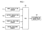
- Fig. 1 is a block diagram showing a structure of a belt clamping pressure setting device according to a first embodiment of the invention.
- the belt clamping pressure setting device sets a belt clamping pressure to optima state for a continuously variable transmission (CVT) comprising a primary belt pulley at an input shaft-side, a secondary belt pulley at an output shaft-side and a belt running between the primary belt pulley and the secondary belt pulley.
- CVT continuously variable transmission
- Each pulley includes a fixed sheave, and a movable sheave urged towards the fixed sheave.
- the belt clamping pressure setting device comprises: an input revolution sensor 11 which generates a revolution pulse signal according to a number of revolutions of the primary belt pulley; an output rotation sensor 12 which generates a revolution pulse signal according to the number of revolutions of the secondary belt pulley; a throttle position sensor 13 which outputs a sensor signal according to a degree of opening of a throttle valve in an engine; an intake pressure sensor 14 which outputs a sensor signal according to the intake pressure of the engine; a CVT hydraulical control valve 15 which controls the hydraulics to set the belt clamping pressure; and an electronic control unit (hereinafter, called as "ECU") 20 which controls the CVT hydraulical control valve 15.
- ECU electronice control unit
- Fig. 2 is a block diagram showing a configuration of the ECU 20.
- the ECU 20 comprises: an input revolution number detection circuit 21 that detects a number of input revolutions for the primary belt pulley; an output revolution number detection circuit 22 that detects a number of output revolutions for the secondary belt pulley; an input torque detection circuit 23 that detects torque input to the primary belt pulley; a speed reducing ratio computing circuit 24 which computes a speed reducing ratio ⁇ ; a reference clamping pressure computing circuit 25 which computes a reference clamping pressure; a torque fluctuation correcting clamping pressure computing circuit 26 which computes a correcting clamping pressure according to the input torque fluctuations; and a required clamping pressure computing circuit 27 which computes a required clamping pressure.
- the input revolution number detection circuit 21 detects the number of input revolutions Nin [rpm], based on the revolution pulse signal from the input revolution sensor 11, and supplies the number of input revolutions Nin to the speed reducing ratio computing circuit 24 and to the torque fluctuation correcting clamping pressure computing circuit 26.
- the output revolution number detection circuit 22 detects the number of output revolutions Nout [rpm], based on the revolution pulse signal from the output revolution sensor 12, and supplies the number of output revolutions Nout to the speed reducing ratio computing circuit 24.
- the input torque detection circuit 23 detects an average input torque Tin from the engine to the primary belt pulley, based on an amount the throttle valve is opened, which is based on the sensor signal from the throttle position sensor 13, and on an intake pressure (amount of air inflow), which is based on the sensor signal from the intake pressure sensor 12.
- the reference clamping pressure computing circuit 25 computes a reference clamping pressure Fc_b using the input torque Tin detected by the input torque detection circuit 23, the speed reducing ratio ⁇ computed by the speed reducing ratio computing circuit 24, and predetermined parameters.
- a computing formula for the reference clamping pressure Fc_b will be described later.
- the steady-state input torque Tin can be estimated as described above, using an amount the throttle valve is opened and the amount of air inflow.
- fluctuations in the input torque (fluctuation amplitude) caused by engine revolution explosions cannot be estimated.
- the torque fluctuation correcting clamping pressure computing circuit 26 computes a correcting clamping pressure ⁇ Fc so that macro slip can be prevented even when a maximum torque fluctuation for the input torque is caused.
- the torque fluctuation correcting clamping pressure computing circuit 26 stores a table of torque fluctuation amplitude rates.
- the table of torque fluctuation amplitude rates shows relationships between the number of input revolutions Nin, the speed reducing ratio ⁇ , and the torque fluctuation amplitude rate T_Rlim at a macro slip limit.
- the table of torque fluctuation amplitude rates indicates, for example, the relationship shown next.
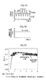
- Figs. 3A through 3C are views showing the torque fluctuation amplitude rates, which correspond to torque fluctuation frequencies, at the macro slip limit.
- Fig. 3A is a case in which the speed reducing ratio ⁇ is 0.65;
- Fig. 3B is a case in which the speed reducing ratio ⁇ is 1.0; and
- Fig. 3C is a case in which the speed reducing ratio ⁇ is 1.51.
- T_Rlim a torque fluctuation amplitude rate [%] at a macro slip limit (namely, a torque fluctuation amplitude, for which the macro slip is not caused at the reference clamping pressure Fc_b, /Tin)
- T_Rmax a maximum value [%] of expected torque fluctuation amplitude rates (namely, a maximum value of the torque fluctuation amplitudes/Tin).
- Fig. 3 shows that the T_Rlim has properties of linearly increasing in accordance with an increase in the torque fluctuation frequency f and increasing in accordance with an increase in the speed reducing ratio ⁇ .
- T_Rmax is a constant value in the embodiment.
- the correcting clamping pressure ⁇ Fc is required in order to prevent the macro slip. Since the macro slip is not caused in an area in which T_Rlim is equal to or larger than T_Rmax, the correcting clamping pressure ⁇ Fc is not required.
- the table of torque fluctuation amplitude rates can indicate relations between the number of input revolutions Nin and the torque fluctuation amplitude rates T_Rlim at the macro slip limit at not only the speed reducing ratios ⁇ shown in Figs. 3A through 3C, but also at various of ratios ⁇ ,.
- the torque fluctuation correcting clamping pressure computing circuit 26 obtains the torque fluctuation amplitude rates T_Rlim corresponding to the number of input revolutions and the speed reducing ratios ⁇ by referring to the table of torque fluctuation amplitude rates.
- the circuit 26 computes torque fluctuation ⁇ T using the torque fluctuation amplitude rates T_Rlim. Then, when the torque fluctuation ⁇ T is larger than 0, the correcting clamping pressure ⁇ Fc is computed, and, when the torque fluctuation ⁇ T is equal to or smaller than 0, the correcting clamping pressure ⁇ Fc made to by 0.
- a computing formula for the correcting clamping pressure ⁇ Fc will be described later.
- the required clamping pressure computing circuit 27 computes required belt clamping pressure Fc based on the reference clamping pressure Fc_b and the correcting clamping pressure ⁇ Fc. Then, the belt clamping pressure of the CVT is set so that the above-described required belt clamping pressure Fc is obtained.
- the ECU 20 sets the belt clamping pressure according to the following procedure so that the belt clamping pressure corresponds to the input torque fluctuations.
- Fig. 4 is a flow diagram showing the processing procedure of the ECU 20.
- Each component circuit in the ECU 20 executes predetermined processing from a step ST1 to a step ST9 in this order.
- the reference clamping pressure computing circuit 25 reads the input torque Tin detected by the input torque detection circuit 23 and the speed reducing ratio ⁇ computed by the speed reducing ratio computing circuit 24.
- the torque fluctuation correcting clamping pressure computing circuit 26 reads the number of input revolutions Nin detected by the input revolution number detection circuit 21, the input torque Tin detected by the input torque detection circuit 23, and the speed reducing ratio ⁇ computed by the speed reducing ratio computing circuit 24. Then, the processing proceeds to a step ST2.
- the reference clamping pressure computing circuit 25 computes a diameter R2 of belt charge (namely, a function of the speed reducing ratio ⁇ ) for the secondary sheave, using the speed reducing ratio ⁇ . Then, the reference clamping pressure Fc_b is computed according to the following formula (1), using the input torque Tin, the speed reducing ratio ⁇ , the diameter R2 of belt charge, and the predetermined parameters.
- the formula (2) is a computing formula for a four-cylinder engine, however, the formula (2) of course can be changed according to the number of cylinders. Moreover, the number of engine revolutions may be used instead of the number of input revolutions Nin.
- the torque fluctuation correcting clamping pressure computing circuit 26 calculates the torque fluctuation amplitude rates T_Rlim at the macro slip limit by referring to the table of torque fluctuation amplitude rates under conditions of the speed reducing ratio ⁇ and the torque fluctuation frequency f obtained at the step ST3. Then, the processing proceeds to a step ST5.
- the torque fluctuation correcting clamping pressure computing circuit 26 calculates the torque fluctuation ⁇ T to be corrected in accordance with a computing formula (3), using the input torque Tin detected in the input torque detection circuit 23, the torque fluctuation amplitude rates T_Rlim obtained at the step ST4, and a maximum value T_Rmax of predetermined torque fluctuation amplitude rates. Then, the processing proceeds to a step ST6.
- ⁇ T (T_R max- T_R lim) ⁇ Tin
- the torque fluctuation correcting clamping pressure computing circuit 26 judges whether the torque fluctuation ⁇ T is larger than 0 or not. Then, the processing proceeds to a step ST7 when the torque fluctuation ⁇ T is larger than 0 and proceeds to a step ST8 when the torque fluctuation ⁇ T is equal to or smaller than 0.
- the torque fluctuation correcting clamping pressure computing circuit 26 computes the correcting clamping pressure ⁇ Fc according to a formula (4), using the diameter R2 of belt charge at the secondary sheave, the speed reducing ratio ⁇ , the torque fluctuation ⁇ T, and the predetermined parameters which have been set beforehand.
- the processing proceeds to the step ST9.
- ⁇ Fc ⁇ T ⁇ ⁇ ⁇ cos ( ⁇ ) 2 ⁇ ⁇ max ⁇ R 2
- the torque fluctuation correcting clamping pressure computing circuit 26 sets the correcting clamping pressure ⁇ Fc as 0 at the step ST8.
- the processing proceeds to the step ST9.
- the reason being that the macro slip can be prevented only with the reference clamping pressure Fc_b. Thereby, increasing belt clamping pressure more than necessary is prevented, improving fuel consumption.
- the required clamping pressure computing circuit 27 computes the required belt clamping pressure Fc by adding of the correcting clamping pressure ⁇ Fc to the reference clamping pressure Fc_b in accordance with a computing formula (5).
- Fc Fc_b + ⁇ Fc
- the required clamping pressure computing circuit 27 controls the CVT hydraulical control valve 15 shown in Fig. 1 so that the belt clamping pressure becomes the required belt clamping pressure Fc.
- the belt clamping pressure setting device can ensure prevention of the belt slip by computing, according to the torque fluctuation frequency f, that is, the number of input revolutions Nin, the correcting clamping pressure ⁇ Fc which is required to prevent the macro slip caused by the torque fluctuation.
- the belt clamping pressure setting device can reduce the pump loss in the CVT hydraulic control to improve the fuel consumption, because the correcting clamping pressure ⁇ Fc is not required at a predetermined number of input revolutions (1500 rpm in the embodiment as shown in the Fig. 13 described later) or more.
- the belt clamping pressure setting device can realize both of prevention of the belt slip and improvement of the fuel consumption by setting necessary and minimum belt clamping pressure according to the number of input revolutions when too much torque is instantaneously caused during the fluctuations of the input torque.
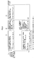
- Fig. 5 is a block diagram showing a configuration of the ECU 20A in a belt clamping pressure setting device according to the second embodiment.
- the ECU 20A comprises a torque fluctuation computing circuit 28 and a clamping pressure computing circuit 29, in stead of the reference clamping pressure computing circuit 25, the torque fluctuation correcting clamping pressure computing circuit 26, and the required clamping pressure computing circuit 27 in the ECU 20 shown in Fig. 2.
- the torque fluctuation computing circuit 28 stores the table of torque fluctuation amplitude rates which explained in the first embodiment in order to compute the torque fluctuation ⁇ T to be corrected.
- the torque fluctuation computing circuit 28 computes the torque fluctuation ⁇ T, based on the a number of input revolutions Nin detected by the input revolution number detection circuit 21, the input torque Tin detected by the input torque detection circuit 23, and the speed reducing ratio ⁇ computed by the speed reducing ratio computing circuit 24.
- the torque fluctuation computing circuit 28 calculates the torque fluctuation ⁇ T to be corrected by processing based on the same steps as those from ST3 through ST5 which are shown in Fig. 4.
- the torque fluctuation computing circuit 28 supplies the calculated torque fluctuation ⁇ T to the clamping pressure computing circuit 29 as it is when the torque fluctuation ⁇ T is larger than 0.
- the torque fluctuation ⁇ T is set to be 0, and the set torque fluctuation ⁇ T is supplied to the clamping pressure computing circuit 29.
- the clamping pressure computing circuit 29 computes clamping pressure Fc according to the following formula (6), using the input torque Tin detected by the input torque detection circuit 23, the torque fluctuation ⁇ T supplied from the torque fluctuation computing circuit 28, and predetermined parameters.
- Fc ( Tin + ⁇ T ) ⁇ y ⁇ cos( ⁇ ) 2 ⁇ ⁇ max ⁇ R 2 - ⁇ N
- the belt clamping pressure setting device can ensure prevention of the belt slip by computing, according to the torque fluctuation frequency f, that is, the number of input revolutions Nin, the torque fluctuation ⁇ T required to prevent the macro slip caused by the torque fluctuation.
- the belt clamping pressure setting device can reduce the pump loss in the CVT hydraulic control to improve the fuel consumption, because the torque fluctuation ⁇ T is not required at the predetermined number of input revolutions (1500 rpm in the embodiment) or more.
- the ECU 20 may carry out the computing processing using the number of engine revolutions, instead of the number of input revolutions Nin, in the above-described first and second embodiments.
- the table of torque fluctuation amplitude rates used in the first and second embodiments will be explained.
- the table of torque fluctuation amplitude rates is made, based on simulation.
- Fig. 6 is a view explaining a simulation model by which the table of torque fluctuation amplitude rates is prepared.
- the simulation model is made, considering a CVT bench mark test.
- torque control is applied to the input side, and revolution number control is applied to the output side.
- R1 is a diameter of belt charge at the primary belt pulley, and Nout is an output torque.
- Fig. 7A is a view showing input torque Tin [Nm]
- Fig. 7C is a view showing belt ⁇ characteristics for belt slip rates.
- Revolution number testing apparatus at the input side sets average input torque Toff as critical torque just before the macro slip is caused, and supplies a sinusoidal torque fluctuation amplitude Tamp about the average input torque Toff.
- the number of revolutions of the revolution number testing apparatus at the output side, and the speed ratio of the CVT are ideally controlled. That is, the number of revolutions at the output side and the speed ratio of the CVT are kept at a constant value at any time.
- the belt slip rate of the CVT is calculated, based on the difference between the belt speed and the speed of the secondary sheave when the sheave speed of the primary belt pulley on the supposition that there is no belt slip is assumed to be the belt speed.
- the ⁇ characteristics of the belt at the secondary belt pulley side are obtained by application of curve fitting to the numbers of revolutions and the speed reducing ratio in ⁇ measurement results of a CVT in actual use, respectively.
- Fig. 8 is a block diagram of a computing processing unit for the simulation model.
- the computing processing unit of the simulation model comprises: a primary belt pulley angular speed computing section 31; a primary belt pulley speed computing section 32; a belt slip rate computing section 33; a secondary belt pulley output torque computing section 34; and a secondary belt pulley speed computing section 35.
- the primary belt pulley angular speed computing section 31 computes a primary belt pulley angular speed ⁇ 1 according to a formula (7), using the input torque Tin, the speed reducing ratio ⁇ , the output torque Tout computed in the secondary belt pulley output torque computing section 34.
- ⁇ 1 ⁇ (Tin - Tout
- Jp is primary belt pulley inertia shown in Fig. 6.
- the primary belt pulley speed computing section 32 computes primary belt pulley speed Prim_V according to a formula (8), using the primary belt pulley angular speed ⁇ 1 computed in the primary belt pulley angular speed computing section 31.
- Prim_V ⁇ 1 ⁇ R 1
- the belt slip is decided, based on the belt slip rate Slip obtained as described above.
- the secondary belt pulley output torque computing section 34 computes the output torque Tout according to a formula (10) using the belt slip rate Slip computed in the belt slip rate computing section 33.
- the number of output revolutions Nout meets a formula (11).
- the belt ⁇ meets a formula (12) which is a tire model with the name of the Magic Formula.
- the secondary belt pulley speed computing section 35 computes a secondary belt pulley speed Secd_V according to a formula (13), using a secondary belt pulley angular speed ⁇ 2.
- Secd_V ⁇ 2 ⁇ R2
- Figs. 9A through 9C are views showing the torque fluctuation amplitude rates corresponding to the torque fluctuation frequencies f for each number of input revolutions: Fig. 9A is for a speed reducing ratio ⁇ of 0.65; Fig. 9B is for a ratio ⁇ of 1.0; and Fig. 9C is for a ratio ⁇ of 1.51.
- Figs. 9A through 9C indicate the following characteristics for the macro slip limit of the torque fluctuation amplitude rates.
- (Characteristic 1) A larger number of input revolutions causes the larger limit of the macro slip in the same torque fluctuation frequency.
- (Characteristic 2) The limit of the macro slip is larger when the speed is more reduced.
- Fig. 10A is a view showing the input torque;
- Fig. 10 B is that showing the number of input revolutions;
- Fig. 10C is that showing the fluctuation in the slip speed;
- Fig. 10D is that showing the belt slip rate; and
- Fig. 10E is that showing the belt ⁇ .
- Fig. 11 is a view showing the belt ⁇ characteristics to the belt slip rates for each speed reducing ratio ⁇ .
- the belt slip rates (inverse black-triangle marks in the drawing) at the belt ⁇ max become larger when the speed is more reduced (the speed reducing ratio becomes smaller). That is, it becomes more difficult to exceed the ⁇ max when the speed is more reduced, and the macro slip limit becomes larger.
- Figs. 12A and 12B are views showing the changes in the input torque and the belt ⁇ with respect to time: Fig. 12A is for a torque fluctuation frequency f of 10 [Hz] (no macro slip); and Fig. 12B is for a torque fluctuation frequency f of 5 [Hz].
- a lower torque fluctuation frequency f causes the more preferable response of the pulley inertia to the input torque. Moreover, lower torque fluctuation frequency f causes the larger change in the number of revolutions, that is, the larger belt slip rate by the torque fluctuation.
- Figs. 13A and 13B are views showing the belt ⁇ characteristics corresponding to the belt slip rate: Fig. 13A is for a torque fluctuation frequency f of 10 [Hz] (no macro slip); and Fig. 13B is for a torque fluctuation frequency f of 5 [Hz] (with macro slip); That is, the belt slip rate in Fig. 12 is plotted in abscissa, and the belt ⁇ is done in ordinate in the Figs. 13A and 13B in order to show the results of examinations on conditions under which the macro slip is caused.
- a ⁇ margin, as shown in Fig. 13A, is required to prevent the macro slip. That is, a belt ⁇ at a point, after a maximum point at which the belt ⁇ exceeds the ⁇ max under assumption that a point at which critical average torque just before the macro slip is caused is applied is set as a starting point, is required to be larger than the critical ⁇ . Unless the above requirement is met, the macro slip occurs.
- Figs. 14A through 14C are views showing the torque fluctuation amplitude rate at the macro slip limit to the number of input revolutions: Fig. 14A is for a speed reducing ratio ⁇ of 0.65; Fig. 14B is for a speed reducing ratio ⁇ of 1.0; and Fig. 14C is for a speed reducing ratio ⁇ of 1.51.
- Figs. 14A through 14C the correcting clamping pressure ⁇ Fc is required in a low idling speed area in which the number of input revolutions are within the range of 750 rpm to 1400 rpm. But the correcting clamping pressure ⁇ Fc is unnecessary in an area in which the number of input revolutions is 1400 rpm or more.
- Figs. 3A through 3C are obtained when the number of input revolutions Nin is converted into the torque fluctuation frequency f according to the above-described formula (2). That is, the table of torque fluctuation amplitude rates is corresponding to Figs. 13A and 13B in which the above-described simulation results have been summarized.
Landscapes
- Engineering & Computer Science (AREA)
- General Engineering & Computer Science (AREA)
- Mechanical Engineering (AREA)
- Control Of Transmission Device (AREA)
Abstract
Description
a second aspect of the invention is to provide a belt clamping pressure setting device comprising: a belt clamping pressure setting means for setting a belt clamping pressure of a continuously variable transmission that includes an input-side pulley, an output-side pulley, and a belt running between the input-side pulley and the out-side pulley; an input revolution detection means for detecting a number of input revolutions of the input-side pulley; an output revolution detection means for detecting a number of output revolutions of the output-side pulley; an input torque detection means for detecting an input torque to the input-side pulley; a torque fluctuation computing means for computing a torque fluctuation to be corrected in accordance with the number of input revolutions detected by the input revolution detection means or a torque fluctuation frequency obtained from the number of input revolutions; and a belt clamping pressure computing means for computing the belt clamping pressure to be set by a belt clamping pressure setting means, based on the number of input revolutions detected by the input revolution detection means, the number of output revolutions detected by the output revolution detection means, the input torque detected by the input torque detection means, and the torque fluctuation computed by the torque fluctuation computing means.
(namely, a torque fluctuation amplitude, for which the macro slip is not caused at the reference clamping pressure Fc_b, /Tin), T_Rmax: a maximum value [%] of expected torque fluctuation amplitude rates
(namely, a maximum value of the torque fluctuation amplitudes/Tin).
(Characteristic 1) A larger number of input revolutions causes the larger limit of the macro slip in the same torque fluctuation frequency.
(Characteristic 2) The limit of the macro slip is larger when the speed is more reduced.
(Characteristic 3) The torque fluctuation amplitude rate linearly increases with the rise in the torque fluctuation frequency.
Claims (14)
- A belt clamping pressure setting device comprising:a belt clamping pressure setting means for setting a belt clamping pressure of a continuously variable transmission that includes an input-side pulley, an output-side pulley, and a belt running between the input-side pulley and the out-side pulley;an input revolution detection means for detecting a number of input revolutions of the input-side pulley;an output revolution detection means for detecting a number of output revolutions of the output-side pulley;an input torque detection means for detecting an input torque to the input-side pulley;a reference clamping pressure computing means for computing a reference clamping pressure, based on the number of input revolutions detected by the input revolution detection means, the number of output revolutions detected by the output revolution detection means, and the input torque detected by the input torque detection means; anda belt clamping pressure computing means for computing the belt clamping pressure to be set by the belt clamping pressure setting means based on the reference clamping pressure and a correction value computed in accordance with the number of input revolutions detected by the input revolution detection means or a torque fluctuation frequency obtained from the number of input revolutions.
- A belt clamping pressure setting device according to claim 1,
wherein the belt clamping pressure computing means computes the belt clamping pressure, based on the reference clamping pressure and the correction value computed in accordance with the number of input revolutions or the torque fluctuation frequency when the number of input revolutions detected by the input revolution detection means is in a low area, or when the torque fluctuation frequency obtained from the number of input revolutions is in a low area. - A belt clamping pressure setting device according to claim 1, further comprising
a speed reducing ratio computing means for computing a speed reducing ratio, based on the number of input revolutions detected by the input revolution detection means, and the number of output revolutions detected by the output revolution detection means, wherein
the belt clamping pressure computing means computes the correction value in accordance with the speed reducing ratio computed by the speed reducing ratio computing means and the number of input revolutions or the torque fluctuation frequency. - A belt clamping pressure setting device according to claim 3, wherein
the belt clamping pressure computing means:refers to a table displaying a relationship between each of the speed reducing ratio, the input torque fluctuation amplitude at or before a macro slip limit and the number of input revolutions or the torque fluctuation frequency;obtains an input torque frequency amplitude rate at or before the macro slip limit based on the speed reducing ratio calculated by the speed reducing ratio detecting means and the number of input revolutions detected by the input revolution detecting means or the torque fluctuation frequency obtained from the number of input revolutions; andcomputes the correction value using the obtained input torque frequency amplitude rate. - A belt clamping pressure setting device, comprising:a belt clamping pressure setting means for setting a belt clamping pressure of a continuously variable transmission that includes an input-side pulley, an output-side pulley, and a belt running between the input-side pulley and the out-side pulley;an input revolution detection means for detecting a number of input revolutions of the input-side pulley;an output revolution detection means for detecting a number of output revolutions of the output-side pulley;an input torque detection means for detecting an input torque to the input-side pulley;a torque fluctuation computing means for computing a torque fluctuation to be corrected in accordance with the number of input revolutions detected by the input revolution detection means or a torque fluctuation frequency obtained from the number of input revolutions; anda belt clamping pressure computing means for computing the belt clamping pressure to be set by a belt clamping pressure setting means, based on the number of input revolutions detected by the input revolution detection means, the number of output revolutions detected by the output revolution detection means, the input torque detected by the input torque detection means, and the torque fluctuation computed by the torque fluctuation computing means.
- A belt clamping pressure setting device according to claim 5, further comprising:a speed reducing ratio computing means for computing a speed reducing ratio, based on the number of input revolutions detected by the input revolution detection means, and the number of output revolutions detected by the output revolution detection means, whereinthe torque fluctuation computing means computes the torque fluctuation in accordance with the speed reducing ratio computed by the speed reducing ratio computing means.
- A belt clamping pressure setting device according to claim 6, wherein
the torque fluctuation computing means:refers to a table displaying a relationship between each of the speed reducing ratio, the input torque fluctuation amplitude at or before a macro slip limit and the number of input revolutions or the torque fluctuation frequency;obtains an input torque frequency amplitude rate at or before the macro slip limit based on the speed reducing ratio calculated by the speed reducing ratio detecting means and the number of input revolutions detected by the input revolution detecting means or the torque fluctuation frequency obtained from the number of input revolutions; andcomputes the torque fluctuation using the obtained input torque frequency amplitude rate. - A belt clamping pressure setting device according to claim 4, wherein,
the table indicates a relationship in which the input torque fluctuation amplitude rate at or before a macro slip limit increases in accordance with the number of input revolutions increasing or the torque fluctuation frequency getting higher. - A belt clamping pressure setting device according to claim 8, wherein,
the table indicates a relationship in which the input torque fluctuation amplitude rate at or before a macro slip limit linearly increases in accordance with the number of input revolutions increasing or the torque fluctuation frequency getting higher. - A belt clamping pressure setting device according to claim 8, wherein,
the table indicates a relationship in which the input torque fluctuation amplitude rate at or before a macro slip limit increases in accordance with the speed reducing ratio increasing. - A belt clamping pressure setting method for setting a belt clamping pressure of a continuously variable transmission that includes an input-side pulley, an output-side pulley, and a belt running between the input-side pulley and the out-side pulley, the method comprising:a number of input revolutions of the input-side pulley a number of output revolutions of the output-side pulley, and input torque to the input-side pulley from an input revolution detection means, an output revolution detection means, and an input torque detection means, respectively;computing a reference clamping pressure, based on the number of input revolutions, the number of output revolutions, and the input torque;computing the belt clamping pressure, based on the reference clamping pressure and a correction value computed in accordance with the number of input revolutions or a torque fluctuation frequency obtained from the number of input revolutions.
- A belt clamping pressure setting method for setting a belt clamping pressure of a continuously variable transmission that includes an input-side pulley, an output-side pulley, and a belt running between the input-side pulley and the out-side pulley, the method comprising:reading a number of input revolutions of the input-side pulley, a number of output revolutions of the output-side pulley, and input torque to the input-side pulley from an input revolution detection means, an output revolution detection means, and an input torque detection means, respectively;computing a torque fluctuation to be corrected, in accordance with the number of input revolutions, or a torque fluctuation frequency obtained from the number of input revolutions; andcomputing the belt clamping pressure, based on the number of input revolutions, the number of output revolutions, the input torque, and the torque fluctuation.
- A belt clamping pressure setting device for setting a belt clamping pressure of a continuously variable transmission that includes an input-side pulley, an output-side pulley, and a belt running between the input-side pulley and the out-side pulley, the device comprising:an input revolution detection means for detecting a number of input revolutions of the input-side pulley;an output revolution detection means for detecting a number of output revolutions of the output-side pulley;an input torque detection means for detecting an input torque to the input-side pulley;a reference clamping pressure computing means for computing a reference clamping pressure, based on the number of input revolutions detected by the input revolution detection means, the number of output revolutions detected by the output revolution detection means, and the input torque detected by the input torque detection means; anda belt clamping pressure computing means for computing the belt clamping pressure to be set by the belt clamping pressure setting means based on the reference clamping pressure and a correction value computed in accordance with the number of input revolutions detected by the input revolution detection means or a torque fluctuation frequency obtained from the number of input revolutions.
- A belt clamping pressure setting device for setting a belt clamping pressure of a continuously variable transmission that includes an input-side pulley, an output-side pulley, and a belt running between the input-side pulley and the out-side pulley, the device comprising:an input revolution detection means for detecting a number of input revolutions of the input-side pulley;an output revolution detection means for detecting a number of output revolutions of the output-side pulley;an input torque detection means for detecting an input torque to the input-side pulley;a torque fluctuation computing means for computing a torque fluctuation to be corrected in accordance with the number of input revolutions detected by the input revolution detection means or a torque fluctuation frequency obtained from the number of input revolutions; anda belt clamping pressure computing means for computing the belt clamping pressure to be set by a belt clamping pressure setting means, based on the number of input revolutions detected by the input revolution detection means, the number of output revolutions detected by the output revolution detection means, the input torque detected by the input torque detection means, and the torque fluctuation computed by the torque fluctuation computing means.
Applications Claiming Priority (2)
| Application Number | Priority Date | Filing Date | Title |
|---|---|---|---|
| JP2003149451 | 2003-05-27 | ||
| JP2003149451A JP3947134B2 (en) | 2003-05-27 | 2003-05-27 | Belt clamping pressure setting device |
Publications (3)
| Publication Number | Publication Date |
|---|---|
| EP1482216A2 true EP1482216A2 (en) | 2004-12-01 |
| EP1482216A3 EP1482216A3 (en) | 2009-04-22 |
| EP1482216B1 EP1482216B1 (en) | 2011-06-22 |
Family
ID=33128224
Family Applications (1)
| Application Number | Title | Priority Date | Filing Date |
|---|---|---|---|
| EP04012366A Expired - Lifetime EP1482216B1 (en) | 2003-05-27 | 2004-05-25 | Device and method for setting belt clamping pressure |
Country Status (3)
| Country | Link |
|---|---|
| US (1) | US7294075B2 (en) |
| EP (1) | EP1482216B1 (en) |
| JP (1) | JP3947134B2 (en) |
Cited By (5)
| Publication number | Priority date | Publication date | Assignee | Title |
|---|---|---|---|---|
| WO2009006943A1 (en) * | 2007-07-11 | 2009-01-15 | Robert Bosch Gmbh | Method for controlling a friction-type continuously variable transmission and a transmission equipped with means for carrying out the method |
| NL2002373C2 (en) * | 2008-12-24 | 2010-06-28 | Bosch Gmbh Robert | Method for controlling a friction transmission such as a friction clutch or a continuously variable transmission. |
| US8914201B2 (en) | 2009-04-30 | 2014-12-16 | Nissan Motor Co., Ltd. | Controller and control method of belt type continuously variable transmission |
| US8914203B2 (en) | 2009-12-15 | 2014-12-16 | Jatco Ltd | Device and method for controlling a belt-type continuously variable transmission for a vehicle |
| US8914204B2 (en) | 2009-12-15 | 2014-12-16 | Jatco Ltd | Device and method for controlling a belt-type continuously variable transmission for a vehicle |
Families Citing this family (18)
| Publication number | Priority date | Publication date | Assignee | Title |
|---|---|---|---|---|
| JP4641852B2 (en) | 2005-04-11 | 2011-03-02 | ジヤトコ株式会社 | Shift control device for belt type continuously variable transmission |
| US7832297B2 (en) | 2005-04-19 | 2010-11-16 | Hewatt Chris B | Method and apparatus for gyroscopic propulsion |
| JP5246420B2 (en) * | 2008-03-12 | 2013-07-24 | 本田技研工業株式会社 | Flip transmission device slip detection device |
| US20100131232A1 (en) * | 2008-11-21 | 2010-05-27 | Taylor Timothy M | Belt slip meter |
| JP5159668B2 (en) * | 2009-02-26 | 2013-03-06 | ダイハツ工業株式会社 | Noise reduction device for chain type continuously variable transmission |
| WO2010125666A1 (en) | 2009-04-30 | 2010-11-04 | ジヤトコ株式会社 | Belt‑based continuously variable transmission control device and control method |
| RU2490533C2 (en) | 2009-04-30 | 2013-08-20 | Ниссан Мотор Ко., Лтд | Device and method to control continuously variable transmission of belt type |
| RU2483235C1 (en) * | 2009-04-30 | 2013-05-27 | Ниссан Мотор Ко., Лтд | Control device and control method of belt stepless transmission |
| BRPI0924736A2 (en) * | 2009-04-30 | 2016-01-26 | Nissan Motor | belt type continuously variable transmission controller and control method |
| JP4908572B2 (en) * | 2009-10-30 | 2012-04-04 | 本田技研工業株式会社 | Control device for continuously variable transmission |
| CN106200616B (en) * | 2010-05-14 | 2019-11-19 | 久益环球表层采矿公司 | Periodic decomposition analysis for remote machine monitoring |
| KR20120107641A (en) | 2011-03-22 | 2012-10-04 | 현대자동차주식회사 | Clamp force control method for continuous variable transmission |
| JP6262549B2 (en) * | 2014-01-28 | 2018-01-17 | 本田技研工業株式会社 | Pulley thrust control device for continuously variable transmission |
| JP6262052B2 (en) * | 2014-03-27 | 2018-01-17 | ジヤトコ株式会社 | Control device for continuously variable transmission |
| EP3276217A4 (en) * | 2015-03-23 | 2018-03-21 | Jatco Ltd. | Vehicle and vehicle control method |
| JP6494671B2 (en) * | 2017-01-13 | 2019-04-03 | 本田技研工業株式会社 | Side pressure control device for continuously variable transmission |
| JP6607205B2 (en) * | 2017-01-19 | 2019-11-20 | トヨタ自動車株式会社 | Vehicle control device |
| CN119802208B (en) * | 2023-10-11 | 2025-12-05 | 上海汽车集团股份有限公司 | A method and related apparatus for processing gear shifting. |
Citations (2)
| Publication number | Priority date | Publication date | Assignee | Title |
|---|---|---|---|---|
| US4631043A (en) | 1984-05-03 | 1986-12-23 | Toyota Jidosha Kabushiki Kaisha | Hydraulic control apparatus for a continuously variable transmission |
| WO2003027540A1 (en) | 2001-09-28 | 2003-04-03 | Toyota Jidosha Kabushiki Kaisha | Slippage detection system and method for continuously variable transmutations |
Family Cites Families (8)
| Publication number | Priority date | Publication date | Assignee | Title |
|---|---|---|---|---|
| US5092198A (en) * | 1989-12-19 | 1992-03-03 | Mazda Motor Corporation | Control apparatus for stepless transmission |
| JPH04357336A (en) | 1991-02-08 | 1992-12-10 | Mitsubishi Motors Corp | Method for controlling oil pressure |
| JP4480862B2 (en) * | 1999-09-07 | 2010-06-16 | 本田技研工業株式会社 | Control device for hybrid vehicle |
| DE10050218A1 (en) * | 2000-10-11 | 2002-04-25 | Volkswagen Ag | Method for pressure force control for continuously variable transmission entails creating regulating variable for the pressure force by using oscillation characteristic of RPM actual gearing up registered by sensors on variator |
| JP3633484B2 (en) * | 2001-01-22 | 2005-03-30 | トヨタ自動車株式会社 | Control device for vehicle having internal combustion engine and continuously variable transmission |
| DE60208455D1 (en) * | 2001-03-02 | 2006-03-30 | Toyota Chuo Kenkyusho Aichi Kk | Pulley Axialdruckgerät for a continuously variable transmission |
| JP3835202B2 (en) * | 2001-05-18 | 2006-10-18 | トヨタ自動車株式会社 | Vehicle drive control device |
| JP3744406B2 (en) | 2001-10-30 | 2006-02-08 | トヨタ自動車株式会社 | Control device for continuously variable transmission for vehicle |
-
2003
- 2003-05-27 JP JP2003149451A patent/JP3947134B2/en not_active Expired - Fee Related
-
2004
- 2004-05-25 EP EP04012366A patent/EP1482216B1/en not_active Expired - Lifetime
- 2004-05-26 US US10/853,554 patent/US7294075B2/en not_active Expired - Fee Related
Patent Citations (2)
| Publication number | Priority date | Publication date | Assignee | Title |
|---|---|---|---|---|
| US4631043A (en) | 1984-05-03 | 1986-12-23 | Toyota Jidosha Kabushiki Kaisha | Hydraulic control apparatus for a continuously variable transmission |
| WO2003027540A1 (en) | 2001-09-28 | 2003-04-03 | Toyota Jidosha Kabushiki Kaisha | Slippage detection system and method for continuously variable transmutations |
Cited By (14)
| Publication number | Priority date | Publication date | Assignee | Title |
|---|---|---|---|---|
| CN101688607B (en) * | 2007-07-11 | 2014-04-23 | 罗伯特·博世有限公司 | Method of controlling a friction-type continuously variable transmission and transmission equipped with means for performing the method |
| US8221286B2 (en) | 2007-07-11 | 2012-07-17 | Robert Bosch Gmbh | Method for controlling a friction-type continuously variable transmission and a transmission equipped with means for carrying out the method |
| WO2009007144A1 (en) * | 2007-07-11 | 2009-01-15 | Robert Bosch Gmbh | Method for controlling a friction-type continuously variable transmission and a transmission equiped with means for carrying out the method |
| WO2009007450A3 (en) * | 2007-07-11 | 2009-04-09 | Bosch Gmbh Robert | Method for controlling a friction-type continuously variable transmission and a transmission equiped with means for carrying out the method |
| CN101688607A (en) * | 2007-07-11 | 2010-03-31 | 罗伯特·博世有限公司 | Method for controlling a friction-type continuously variable transmission and transmission equipped with means for carrying out the method |
| CN101688608B (en) * | 2007-07-11 | 2013-01-23 | 罗伯特·博世有限公司 | Method for controlling friction type stepless transmission device, transmission device equipped with device for implementing the method |
| KR101505224B1 (en) * | 2007-07-11 | 2015-03-23 | 로베르트 보쉬 게엠베하 | Method for controlling a friction-type continuously variable transmission and a transmission equiped with means for carrying out the method |
| WO2009007450A2 (en) | 2007-07-11 | 2009-01-15 | Robert Bosch Gmbh | Method for controlling a friction-type continuously variable transmission and a transmission equiped with means for carrying out the method |
| WO2009006943A1 (en) * | 2007-07-11 | 2009-01-15 | Robert Bosch Gmbh | Method for controlling a friction-type continuously variable transmission and a transmission equipped with means for carrying out the method |
| NL2002373C2 (en) * | 2008-12-24 | 2010-06-28 | Bosch Gmbh Robert | Method for controlling a friction transmission such as a friction clutch or a continuously variable transmission. |
| WO2010074560A1 (en) * | 2008-12-24 | 2010-07-01 | Robert Bosch Gmbh | Method for controlling a friction transmission such as a friction clutch or a continuously variable transmission |
| US8914201B2 (en) | 2009-04-30 | 2014-12-16 | Nissan Motor Co., Ltd. | Controller and control method of belt type continuously variable transmission |
| US8914203B2 (en) | 2009-12-15 | 2014-12-16 | Jatco Ltd | Device and method for controlling a belt-type continuously variable transmission for a vehicle |
| US8914204B2 (en) | 2009-12-15 | 2014-12-16 | Jatco Ltd | Device and method for controlling a belt-type continuously variable transmission for a vehicle |
Also Published As
| Publication number | Publication date |
|---|---|
| US20040242355A1 (en) | 2004-12-02 |
| JP3947134B2 (en) | 2007-07-18 |
| US7294075B2 (en) | 2007-11-13 |
| EP1482216B1 (en) | 2011-06-22 |
| JP2004353703A (en) | 2004-12-16 |
| EP1482216A3 (en) | 2009-04-22 |
Similar Documents
| Publication | Publication Date | Title |
|---|---|---|
| EP1482216A2 (en) | Device and method for setting belt clamping pressure | |
| CN102177371B (en) | Variator TCC slip is effective driveline vibration detection algorithm in controlling | |
| EP1158216A2 (en) | Control apparatus and method of belt-type continuously variable transmission | |
| US20090298644A1 (en) | Idling-stop cancellation control apparatus of vehicle driving system | |
| CN104160182B (en) | The lock-up capacity control apparatus of fluid torque converter | |
| US9046174B2 (en) | Coefficient of friction correction device for belt-type continuously variable transmission | |
| US6427109B1 (en) | Powertrain torque estimate | |
| US8346444B2 (en) | Real time transmission shift quality detection and evaluation utilizing transmission output shaft acceleration | |
| US20060089776A1 (en) | Lock-up clutch control | |
| JP5391348B1 (en) | Diagnosis device for hydraulic control actuator | |
| US6702086B2 (en) | Method and device for controlling and/or regulating the slip of a clutch | |
| KR100411357B1 (en) | Control device for a continuously variable transmission | |
| JP4016562B2 (en) | Shift control device for continuously variable transmission for vehicle | |
| KR987001071A (en) | System for Adjusting the Tension of the contact Part of a Belt Drive Mechanism | |
| JP3714024B2 (en) | Input torque estimation device | |
| JP2001090825A (en) | Transmission input torque calculation device | |
| US6878083B2 (en) | Pump speed compensation for transmission line pressure | |
| JP3591395B2 (en) | Shift control device for hydraulic continuously variable transmission for vehicle | |
| JP3624331B2 (en) | Transmission control device | |
| JPS629054A (en) | Device for controlling line pressure for automatic transmission for car | |
| JPH0450440A (en) | Engine control method for vehicle equipped with cvt system | |
| JPH0396754A (en) | Line pressure control device for automatic transmission | |
| JP3203472B2 (en) | Control device for continuously variable transmission | |
| EP2199578A1 (en) | Torque control device and method for internal combustion engine | |
| JPH0413576B2 (en) |
Legal Events
| Date | Code | Title | Description |
|---|---|---|---|
| PUAI | Public reference made under article 153(3) epc to a published international application that has entered the european phase |
Free format text: ORIGINAL CODE: 0009012 |
|
| 17P | Request for examination filed |
Effective date: 20040616 |
|
| AK | Designated contracting states |
Kind code of ref document: A2 Designated state(s): AT BE BG CH CY CZ DE DK EE ES FI FR GB GR HU IE IT LI LU MC NL PL PT RO SE SI SK TR |
|
| AX | Request for extension of the european patent |
Extension state: AL HR LT LV MK |
|
| PUAL | Search report despatched |
Free format text: ORIGINAL CODE: 0009013 |
|
| AK | Designated contracting states |
Kind code of ref document: A3 Designated state(s): AT BE BG CH CY CZ DE DK EE ES FI FR GB GR HU IE IT LI LU MC NL PL PT RO SE SI SK TR |
|
| AX | Request for extension of the european patent |
Extension state: AL HR LT LV MK |
|
| AKX | Designation fees paid |
Designated state(s): DE FR GB IT |
|
| 17Q | First examination report despatched |
Effective date: 20100528 |
|
| GRAP | Despatch of communication of intention to grant a patent |
Free format text: ORIGINAL CODE: EPIDOSNIGR1 |
|
| RIC1 | Information provided on ipc code assigned before grant |
Ipc: F16H 61/662 20060101AFI20101119BHEP |
|
| GRAS | Grant fee paid |
Free format text: ORIGINAL CODE: EPIDOSNIGR3 |
|
| GRAA | (expected) grant |
Free format text: ORIGINAL CODE: 0009210 |
|
| AK | Designated contracting states |
Kind code of ref document: B1 Designated state(s): DE FR GB IT |
|
| REG | Reference to a national code |
Ref country code: GB Ref legal event code: FG4D |
|
| REG | Reference to a national code |
Ref country code: DE Ref legal event code: R096 Ref document number: 602004033143 Country of ref document: DE Effective date: 20110728 |
|
| PLBE | No opposition filed within time limit |
Free format text: ORIGINAL CODE: 0009261 |
|
| STAA | Information on the status of an ep patent application or granted ep patent |
Free format text: STATUS: NO OPPOSITION FILED WITHIN TIME LIMIT |
|
| 26N | No opposition filed |
Effective date: 20120323 |
|
| REG | Reference to a national code |
Ref country code: DE Ref legal event code: R097 Ref document number: 602004033143 Country of ref document: DE Effective date: 20120323 |
|
| PGFP | Annual fee paid to national office [announced via postgrant information from national office to epo] |
Ref country code: DE Payment date: 20120523 Year of fee payment: 9 |
|
| PGFP | Annual fee paid to national office [announced via postgrant information from national office to epo] |
Ref country code: GB Payment date: 20120523 Year of fee payment: 9 Ref country code: FR Payment date: 20120608 Year of fee payment: 9 |
|
| PGFP | Annual fee paid to national office [announced via postgrant information from national office to epo] |
Ref country code: IT Payment date: 20120518 Year of fee payment: 9 |
|
| REG | Reference to a national code |
Ref country code: GB Ref legal event code: 746 Effective date: 20130215 |
|
| REG | Reference to a national code |
Ref country code: DE Ref legal event code: R084 Ref document number: 602004033143 Country of ref document: DE Effective date: 20130312 |
|
| GBPC | Gb: european patent ceased through non-payment of renewal fee |
Effective date: 20130525 |
|
| PG25 | Lapsed in a contracting state [announced via postgrant information from national office to epo] |
Ref country code: DE Free format text: LAPSE BECAUSE OF NON-PAYMENT OF DUE FEES Effective date: 20131203 |
|
| REG | Reference to a national code |
Ref country code: DE Ref legal event code: R119 Ref document number: 602004033143 Country of ref document: DE Effective date: 20131203 |
|
| PG25 | Lapsed in a contracting state [announced via postgrant information from national office to epo] |
Ref country code: IT Free format text: LAPSE BECAUSE OF NON-PAYMENT OF DUE FEES Effective date: 20130525 |
|
| REG | Reference to a national code |
Ref country code: FR Ref legal event code: ST Effective date: 20140131 |
|
| PG25 | Lapsed in a contracting state [announced via postgrant information from national office to epo] |
Ref country code: GB Free format text: LAPSE BECAUSE OF NON-PAYMENT OF DUE FEES Effective date: 20130525 |
|
| PG25 | Lapsed in a contracting state [announced via postgrant information from national office to epo] |
Ref country code: FR Free format text: LAPSE BECAUSE OF NON-PAYMENT OF DUE FEES Effective date: 20130531 |