EP1482177B1 - Scroll fluid machine - Google Patents
Scroll fluid machine Download PDFInfo
- Publication number
- EP1482177B1 EP1482177B1 EP04076469A EP04076469A EP1482177B1 EP 1482177 B1 EP1482177 B1 EP 1482177B1 EP 04076469 A EP04076469 A EP 04076469A EP 04076469 A EP04076469 A EP 04076469A EP 1482177 B1 EP1482177 B1 EP 1482177B1
- Authority
- EP
- European Patent Office
- Prior art keywords
- scroll
- orbiting
- orbiting scroll
- fixed
- partition wall
- Prior art date
- Legal status (The legal status is an assumption and is not a legal conclusion. Google has not performed a legal analysis and makes no representation as to the accuracy of the status listed.)
- Expired - Lifetime
Links
- 239000012530 fluid Substances 0.000 title claims description 15
- 238000005192 partition Methods 0.000 claims description 14
- 230000007246 mechanism Effects 0.000 claims description 13
- 230000006835 compression Effects 0.000 claims description 4
- 238000007906 compression Methods 0.000 claims description 4
- 238000007599 discharging Methods 0.000 claims 2
- 230000003247 decreasing effect Effects 0.000 description 1
- 238000012423 maintenance Methods 0.000 description 1
- 238000012986 modification Methods 0.000 description 1
- 230000004048 modification Effects 0.000 description 1
- 238000004804 winding Methods 0.000 description 1
Images

Classifications
-
- F—MECHANICAL ENGINEERING; LIGHTING; HEATING; WEAPONS; BLASTING
- F04—POSITIVE - DISPLACEMENT MACHINES FOR LIQUIDS; PUMPS FOR LIQUIDS OR ELASTIC FLUIDS
- F04C—ROTARY-PISTON, OR OSCILLATING-PISTON, POSITIVE-DISPLACEMENT MACHINES FOR LIQUIDS; ROTARY-PISTON, OR OSCILLATING-PISTON, POSITIVE-DISPLACEMENT PUMPS
- F04C23/00—Combinations of two or more pumps, each being of rotary-piston or oscillating-piston type, specially adapted for elastic fluids; Pumping installations specially adapted for elastic fluids; Multi-stage pumps specially adapted for elastic fluids
- F04C23/001—Combinations of two or more pumps, each being of rotary-piston or oscillating-piston type, specially adapted for elastic fluids; Pumping installations specially adapted for elastic fluids; Multi-stage pumps specially adapted for elastic fluids of similar working principle
-
- F—MECHANICAL ENGINEERING; LIGHTING; HEATING; WEAPONS; BLASTING
- F04—POSITIVE - DISPLACEMENT MACHINES FOR LIQUIDS; PUMPS FOR LIQUIDS OR ELASTIC FLUIDS
- F04C—ROTARY-PISTON, OR OSCILLATING-PISTON, POSITIVE-DISPLACEMENT MACHINES FOR LIQUIDS; ROTARY-PISTON, OR OSCILLATING-PISTON, POSITIVE-DISPLACEMENT PUMPS
- F04C18/00—Rotary-piston pumps specially adapted for elastic fluids
- F04C18/02—Rotary-piston pumps specially adapted for elastic fluids of arcuate-engagement type, i.e. with circular translatory movement of co-operating members, each member having the same number of teeth or tooth-equivalents
- F04C18/0207—Rotary-piston pumps specially adapted for elastic fluids of arcuate-engagement type, i.e. with circular translatory movement of co-operating members, each member having the same number of teeth or tooth-equivalents both members having co-operating elements in spiral form
- F04C18/0215—Rotary-piston pumps specially adapted for elastic fluids of arcuate-engagement type, i.e. with circular translatory movement of co-operating members, each member having the same number of teeth or tooth-equivalents both members having co-operating elements in spiral form where only one member is moving
Definitions
- the present invention relates to a scroll fluid machine as defined in the preamble of claim 1.
- a scroll fluid machine such as a scroll vacuum pump, a scroll compressor, a scroll expander or a scroll blower, in which a fixed wrap of a fixed scroll in a housing is engaged with an orbiting wrap of an orbiting scroll rotatably mounted to an eccentric portion of a driving shaft, the orbiting scroll being eccentrically revolved by the driving shaft so that a gas sucked through the circumference or center is pressurized or depressurized as it moves toward the center or circumference and discharged.
- an orbiting scroll rotatably mounted to an eccentric portion of a driving shaft has an orbiting end portion, and a fixed scroll has a fixed end portion.
- An orbiting wrap of the orbiting end portion is engaged with a fixed wrap of the fixed end portion to form a sealed chamber, and there is provided a self-rotation-preventing mechanism for the orbiting scroll.
- the orbiting scroll is eccentrically revolved, and according to a direction of revolving, the volume of the sealed chamber is gradually decreased toward the center or increased toward the circumference, so that fluid sucked through the circumference is introduced to the center under pressurizing or fluid sucked through the center is discharged through the circumference under depressurizing.
- Numerals 10,20 denote first and second scroll engagement actuating portions having the same axis, and are respectively provided in first and second box-like housings 11,21 which faces each other at both sides of a partition wall 30, having first and second fixed scrolls 12,22 and first and second orbiting scrolls 13,23 which are engaged with each other.
- Scroll engagement actuating portions 10,20 are known and will be described as below.
- spiral fixed wraps 15,25 are projected on the inner surface of end portions 14,24 which are outer walls of the first and second housings 11,21, and tip seals 15a,25a are engaged over the top of the fixed wraps 15,25.
- orbiting wraps 17,27 are projected on the outer surfaces of orbiting end portions 16,26 to engage with the fixed wraps 15,25. Tip seals 17a,27a are engaged over the top of the orbiting wraps 17,27.
- Sucking bores 18,28 are formed on the circumference and discharge bores 19,29 are formed on the fixed end portion 14,24 of the housings 11,21 to extend from the middle.
- a driving shaft 32 is rotatably disposed via a bearing 33, and an eccentric portion 34 at the end of the driving shaft 32 is rotatably mounted via a bearing 35 at the center of an orbiting end portion 16 of the orbiting scroll 13 of the first scroll engagement actuating portion 10.
- the orbiting end portions 16,26 of the first and second scroll engagement actuating portions 10,20 are connected to each other by three both-side pin-crank-type self-rotation-preventing mechanisms 36 rotatably mounted and spaced equally on the circumference of the partition wall 30.
- a double-crank shaft 37 is rotatably mounted in the partition wall 30 and eccentrically projecting pins 38,38 are rotatably mounted in the orbiting end portions 16,26.
- the scroll engagement actuating portions 10,20 have the same size and volume, but may have different size, volume or function.
- the orbiting end portion 16 of the first scroll engagement actuating portion 10 is eccentrically revolved and radial size of space between the fixed and orbiting wraps 15 and 17 changes, so that the central portion of the housing 11 is gradually depressurized and a gas sucked through the sucking bore 18 is discharged through a discharge bore 19 at the center.
- the eccentric revolution of the orbiting end portion 16 of the first scroll engagement actuating portion 10 is transmitted to the orbiting end portion 26 of the second scroll engagement actuating portion 20 via the pin-crank-type self-rotation-preventing mechanism 36, so that the orbiting end portion 26 is eccentrically revolved as well, and a gas sucked through the sucking bore 28 is discharged through a discharge bore 29 at the center.
- the scroll engagement actuating portions 10,20 have different volume as above to provide various volume of scroll machines, which is advantageous.
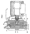
- Fig. 1 illustrates the first and second scroll engagement actuating portions 10,20 are provided separately, but may be connected as shown in Fig. 2 .
- Axial bores 40,41 are formed near the center of an orbiting end portion 24 of a second scroll engagement actuating portion 20 similar to one in Fig. 1 and a partition wall 30, and an annular seal 42 is provided between the orbiting end portion 24 and the partition wall 30 around the bores 40,41.
- a sucking bore 28 is formed without a discharge bore, while only a discharge bore 19 is provided without a sucking bore.
- the other members than the above are the same as those in Fig. 1 , and numeral and description thereof are omitted except especially required ones.
- first and second orbiting scrolls 13,23 are eccentrically revolved at the same time, so that a gas sucked through the sucking bore 28 of the second housing 21 is compressed as it moves toward the center. Then, the gas is transferred with compression via the bores 40,41 and around the orbiting end portion 16, moved to the center via the circumference of the first scroll engagement actuating portion 10, and discharged through the discharge bore 19.
- the positions of the sucking bores 18,28 and discharge bores 19,29 of the first and second scroll engagement actuating portions 10,20 may be changed variously.
- one of the first engagement actuating portions 10,20 is used for pressurizing, while the other is used for depressurizing.
Landscapes
- Engineering & Computer Science (AREA)
- Mechanical Engineering (AREA)
- General Engineering & Computer Science (AREA)
- Rotary Pumps (AREA)
- Applications Or Details Of Rotary Compressors (AREA)
Description
- The present invention relates to a scroll fluid machine as defined in the preamble of claim 1. Such a machine is known e.g. from
EP-A-687 815 - In the scroll fluid machine which is known among persons skilled in the art, an orbiting scroll rotatably mounted to an eccentric portion of a driving shaft has an orbiting end portion, and a fixed scroll has a fixed end portion. An orbiting wrap of the orbiting end portion is engaged with a fixed wrap of the fixed end portion to form a sealed chamber, and there is provided a self-rotation-preventing mechanism for the orbiting scroll.
- By the eccentric portion and the self-rotation-preventing mechanism, the orbiting scroll is eccentrically revolved, and according to a direction of revolving, the volume of the sealed chamber is gradually decreased toward the center or increased toward the circumference, so that fluid sucked through the circumference is introduced to the center under pressurizing or fluid sucked through the center is discharged through the circumference under depressurizing.
- In factories and various workshops, various kinds and capabilities of scroll fluid machines are placed depending on the contents of working. A plurality of different scroll fluid machines are usually disposed in relevant factories, taking account of the type and capability expected in use. However, it is not economical in fixing cost, occupation area, the rate of operation and maintenance.
- The features and advantages of the invention will become more apparent from the following description with respect to embodiments as shown in appended drawings wherein:
-
Fig. 1 is a vertical sectional side view of one embodiment of a scroll fluid machine according to the present invention; and -
Fig. 2 is a vertical sectional view of another embodiment of a scroll fluid machine according to the present invention. - Numerals 10,20 denote first and second scroll engagement actuating portions having the same axis, and are respectively provided in first and second box-
like housings 11,21 which faces each other at both sides of apartition wall 30, having first and secondfixed scrolls 12,22 and first and second orbitingscrolls - Scroll engagement actuating
portions fixed scrolls 12,22, spiral fixedwraps end portions second housings 11,21, andtip seals wraps wraps end portions wraps Tip seals wraps - Sucking
bores discharge bores end portion housings 11,21 to extend from the middle. - In an
axial bore 31 at the center of the fixedend portion 14 of the first housing 11, adriving shaft 32 is rotatably disposed via abearing 33, and aneccentric portion 34 at the end of the drivingshaft 32 is rotatably mounted via abearing 35 at the center of an orbitingend portion 16 of the orbitingscroll 13 of the first scroll engagement actuatingportion 10. - The orbiting
end portions portions mechanisms 36 rotatably mounted and spaced equally on the circumference of thepartition wall 30. Specifically, in the both-side pin-crank-type self-rotation-preventingmechanisms 36, a double-crank shaft 37 is rotatably mounted in thepartition wall 30 and eccentrically projectingpins end portions - The scroll engagement actuating
portions - When the driving
shaft 32 is driven by anelectric motor 39, the orbitingend portion 16 of the first scroll engagement actuatingportion 10 is eccentrically revolved and radial size of space between the fixed and orbitingwraps sucking bore 18 is discharged through adischarge bore 19 at the center. - The eccentric revolution of the orbiting
end portion 16 of the first scroll engagement actuatingportion 10 is transmitted to the orbitingend portion 26 of the second scroll engagement actuatingportion 20 via the pin-crank-type self-rotation-preventingmechanism 36, so that the orbitingend portion 26 is eccentrically revolved as well, and a gas sucked through thesucking bore 28 is discharged through adischarge bore 29 at the center. - By the
single driving shaft 32, two scroll fluid machines are simultaneously driven, which is economical and the external diameters of the scroll engagement actuatingportions - In case that large volume is not required, the scroll engagement actuating
portions - To provide different volumes of the first and second scroll engagement actuating
portions - 1) to make difference in wrap windings of the scroll engagement actuating
portions - 2) to make difference in height of the scroll engagement actuating
portions - 3) make difference in eccentricity of an
eccentric portion 34 of thedriving shaft 32 and apin 38 of a double-crank shaft 37 of the pin-crank-type self-rotation-preventingmechanism 36. -
Fig. 1 illustrates the first and second scroll engagement actuatingportions Fig. 2 . -
Axial bores end portion 24 of a second scroll engagement actuatingportion 20 similar to one inFig. 1 and apartition wall 30, and anannular seal 42 is provided between the orbitingend portion 24 and thepartition wall 30 around thebores second housing 21, only asucking bore 28 is formed without a discharge bore, while only adischarge bore 19 is provided without a sucking bore. The other members than the above are the same as those inFig. 1 , and numeral and description thereof are omitted except especially required ones. - In
Fig. 2 , when adriving shaft 32 is rotated, first and secondorbiting scrolls sucking bore 28 of thesecond housing 21 is compressed as it moves toward the center. Then, the gas is transferred with compression via thebores end portion 16, moved to the center via the circumference of the first scroll engagement actuatingportion 10, and discharged through thedischarge bore 19. - Thus, even if the diameters of the scroll engagement actuating
portions - In the present invention, the positions of the sucking bores 18,28 and
discharge bores portions - In this invention, one of the first engagement actuating
portions - The foregoing merely relates to embodiments of the invention. Various changes and modifications may be made by a person skilled in the art without departing from the scope of claims wherein:
Claims (12)
- A scroll fluid machine comprising:a driving shaft (32);a first scroll engagement actuating portion (10) comprising a first orbiting scroll (13) and a first fixed scroll (12), the first orbiting scroll (13) being connected to the driving shaft (32) and engaged with the first fixed scroll (12);a second scroll engagement actuating portion (20) comprising a second orbiting scroll (23) and a second fixed scroll (22) engaged with the second orbiting scroll (23); anda partition wall(30) between the first and second scroll engagement actuating portions (10,20), whereinsaid first orbiting scroll (13) is connected to said second orbiting Scroll (23) by a pin-crank-type Self-rotation-preventing mechanism (36), passing through a partition wall (30) to revolve together when the first orbiting scroll (13) is driven by the driving shaft (32), characterized in that: said pin-crank-type mechanism (36) is passing through said partition wall (30) near a circumference of said wall (30).
- The machine according to claim 1, wherein orbiting end portions (16, 26) of the first and second scroll engagement actuating portions (10, 20) are connected to each other by three both-side pin-crank-type self-rotation-preventing mechanisms (36).
- The machine according to claim 2, wherein the pin-crank-type self-rotation-preventing mechanisms (36) are rotatably mounted and spaced equally on the circumference of the partition wall (30).
- The machine according to any of the preceding claims, wherein the pin-crank-type self-rotation-preventing mechanism (36) are arranged two transmit eccentric revolution of an orbiting end portion (16) of the first scroll engagement actuating portion (10) to the orbiting end portion (26) of the second scroll engagement, actuating portion (20).
- The machine according to any of the preceding claims, the first and second scroll engagement actuating portions (10, 20) are respectively provided in first and second box-like housings (11,21) which face each other at both sides of the partition wall (30), wherein inner surfaces of the first and second housings (11,21) are provided with spiral fixed wraps (15, 25).
- The machine according to any of the preceding claims, wherein partition wall (30) extends between the first and second orbiting scrolls (13, 23).
- The machine according to any of the preceding claims, wherein the scroll engagement actuating portions 10, 20) have different volume.
- The machine according to any of the preceding claims, wherein the pin-crank-type self-rotation-preventing mechanism (36) comprises a shaft (37) inserted in the partition wall (30) via bearing, a first pin (38) connected to the first orbiting scroll (13) and a second pin (38) connected to the second orbiting scroll (23);
- A scroll fluid machine as claimed in any of the preceding claims wherein the driving shaft (32) comprise an eccentric portion (34) at one end, the first orbiting scroll (13) being rotatably mounted on the eccentric portion (34) of the driving shaft (32), the first fixed scroll (12) having a first fixed wrap (15), the first orbiting scroll (13) having a first orbiting wrap (17) engaged with the first fixed wrap (15) to form a first compression chamber in which pressure is changed towards a center of the first orbiting scroll (13) when the first orbiting scroll (13) is eccentrically revolved by the driving shaft (32) via the eccentric portion (34), the second orbiting scroll (23) being revolved together with the first orbiting scroll (13) by the pin-crank-type self-rotation preventing mechanism (36), the second orbiting scroll (23) having a second orbiting wrap (27) which is engaged with a second fixed wrap (25) of the second fixed scroll (22) to from a second compression chamber in which pressure is changed towards a center of the second orbiting scroll (23) when the second orbiting scroll (23) is revolved together with the first orbiting scroll (13).
- A scroll fluid machine as claimed in any of the preceding claims, wherein a first sucking bore (18) for introducing a first gas into the first scroll engagement actuating portion (10) is formed through a first circumference of a first fixed end portion of a housing, a first discharge bore (19) for discharging the first gas being formed at portion near a center of the first orbiting scroll (13), a second sucking bore (28) for introducing a second gas into the second scroll engagement actuating portion (20) being formed through a second circumference of the second fixed end portion of the housing, a second discharge bore (29) for discharging the second gas being formed at portion near a center of the second orbiting scroll (23).
- A scroll fluid machine as claimed in any of claims 1.9 wherein a first through bore (41) is formed through the partition wall (30), a second through bore (40) being formed through the second orbiting scroll (23) near a center of the orbiting scroll, a gas introduced through a sucking bore (28) of the second scroll engagement actuating portion (20) flowing through the first and second through bores (41, 40) to the first: scroll engagement actuating portion (10) and being discharged through a discharge bore (19).
- The machine according to claim 11, wherein an annular seal (42) is provided between the orbiting end portion (24) and the partition wall (30) around the bores (40, 41.
Applications Claiming Priority (2)
| Application Number | Priority Date | Filing Date | Title |
|---|---|---|---|
| JP2003146609 | 2003-05-23 | ||
| JP2003146609A JP2004346871A (en) | 2003-05-23 | 2003-05-23 | Scroll fluid machine |
Publications (2)
| Publication Number | Publication Date |
|---|---|
| EP1482177A1 EP1482177A1 (en) | 2004-12-01 |
| EP1482177B1 true EP1482177B1 (en) | 2011-11-30 |
Family
ID=33128187
Family Applications (1)
| Application Number | Title | Priority Date | Filing Date |
|---|---|---|---|
| EP04076469A Expired - Lifetime EP1482177B1 (en) | 2003-05-23 | 2004-05-18 | Scroll fluid machine |
Country Status (4)
| Country | Link |
|---|---|
| US (1) | US6942474B2 (en) |
| EP (1) | EP1482177B1 (en) |
| JP (1) | JP2004346871A (en) |
| CN (1) | CN1324219C (en) |
Families Citing this family (11)
| Publication number | Priority date | Publication date | Assignee | Title |
|---|---|---|---|---|
| KR100635818B1 (en) * | 2005-02-04 | 2006-10-19 | 엘지전자 주식회사 | Two Stage Compression Swivel Vane Compressor |
| US20070036668A1 (en) * | 2005-08-09 | 2007-02-15 | Carrier Corporation | Scroll compressor discharge port improvements |
| JP2007198184A (en) * | 2006-01-24 | 2007-08-09 | Sanden Corp | Fluid machine |
| JP4969878B2 (en) * | 2006-03-13 | 2012-07-04 | アネスト岩田株式会社 | Scroll fluid machinery |
| CN101981274B (en) * | 2008-04-07 | 2014-07-02 | 三菱电机株式会社 | Vortex fluid machinery |
| GB201007028D0 (en) * | 2010-04-28 | 2010-06-09 | Edwards Ltd | Scroll pump |
| CN106382167A (en) * | 2015-07-26 | 2017-02-08 | 熵零股份有限公司 | Scroll engine |
| CN112879293B (en) * | 2021-01-28 | 2023-02-28 | 沈阳纪维应用技术有限公司 | Oil-free vortex type vacuum and compression integrated machine |
| CN114754001B (en) * | 2022-05-20 | 2024-04-16 | 重庆超力高科技股份有限公司 | Double-molded-line compressor movable vortex disc anti-rotation structure and vortex compressor |
| CN120367797A (en) * | 2024-01-23 | 2025-07-25 | 罗伯特·博世有限公司 | Scroll compressor having a rotor with a rotor shaft having a rotor shaft with a |
| WO2025220214A1 (en) * | 2024-04-19 | 2025-10-23 | 三菱電機株式会社 | Scroll compressor |
Family Cites Families (7)
| Publication number | Priority date | Publication date | Assignee | Title |
|---|---|---|---|---|
| US4192152A (en) * | 1978-04-14 | 1980-03-11 | Arthur D. Little, Inc. | Scroll-type fluid displacement apparatus with peripheral drive |
| US4424010A (en) * | 1981-10-19 | 1984-01-03 | Arthur D. Little, Inc. | Involute scroll-type positive displacement rotary fluid apparatus with orbiting guide means |
| JPH04269301A (en) * | 1991-02-25 | 1992-09-25 | Hitachi Ltd | Scroll fluid machine |
| JP3249832B2 (en) * | 1991-11-15 | 2002-01-21 | 株式会社日立製作所 | Scroll compressor |
| DE69506036T2 (en) * | 1994-06-17 | 1999-06-10 | Asuka Japan Co., Ltd., Yamaguchi | Spiral displacement machine |
| EP1101943B1 (en) * | 1995-02-28 | 2003-12-03 | Anest Iwata Corporation | Control of a two-stage vacuum pump |
| JP2001093554A (en) * | 1999-09-28 | 2001-04-06 | Toyota Autom Loom Works Ltd | Compression regenerator for fuel cells |
-
2003
- 2003-05-23 JP JP2003146609A patent/JP2004346871A/en active Pending
-
2004
- 2004-05-17 US US10/847,215 patent/US6942474B2/en not_active Expired - Lifetime
- 2004-05-18 EP EP04076469A patent/EP1482177B1/en not_active Expired - Lifetime
- 2004-05-20 CN CNB2004100458020A patent/CN1324219C/en not_active Expired - Fee Related
Also Published As
| Publication number | Publication date |
|---|---|
| CN1324219C (en) | 2007-07-04 |
| JP2004346871A (en) | 2004-12-09 |
| CN1573017A (en) | 2005-02-02 |
| US6942474B2 (en) | 2005-09-13 |
| EP1482177A1 (en) | 2004-12-01 |
| US20040234405A1 (en) | 2004-11-25 |
Similar Documents
| Publication | Publication Date | Title |
|---|---|---|
| JP3129365B2 (en) | Scroll type fluid machine | |
| US4157234A (en) | Scroll-type two stage positive fluid displacement apparatus | |
| CN105190042B (en) | Screw compressor | |
| CN106062369B (en) | scroll compressor | |
| US6942474B2 (en) | Scroll fluid machine | |
| JPH09158852A (en) | Scroll type fluid machine | |
| US5951272A (en) | Scroll compressor having an annular seal for a stationary scroll pressure receiving surface | |
| JP6738170B2 (en) | Scroll compressor | |
| US20220065251A1 (en) | Compressor | |
| US20120177523A1 (en) | Scroll compressor with split type orbitting scroll | |
| US20100209277A1 (en) | Scroll compressor | |
| JP2882902B2 (en) | Scroll compressor | |
| CN100458161C (en) | scroll compressor | |
| JP3089140B2 (en) | Oil pump for hermetic compressor | |
| EP0172674B1 (en) | Scroll type fluid compressor | |
| EP2669523B1 (en) | Scroll compressor | |
| US6193489B1 (en) | Shaft assembly mechanism for scroll compressor | |
| CN108368847B (en) | Scroll compressor having a plurality of scroll members | |
| KR101442547B1 (en) | Scroll compressor | |
| JPH11247761A (en) | Hermetic compressor | |
| JPH0378586A (en) | Scroll type fluid device | |
| JP3105715B2 (en) | Scroll type compressor | |
| JPH0942177A (en) | Scroll compressor | |
| JPH0932775A (en) | Hermetic electric compressor | |
| JP4379945B2 (en) | Scroll compressor |
Legal Events
| Date | Code | Title | Description |
|---|---|---|---|
| PUAI | Public reference made under article 153(3) epc to a published international application that has entered the european phase |
Free format text: ORIGINAL CODE: 0009012 |
|
| AK | Designated contracting states |
Kind code of ref document: A1 Designated state(s): AT BE BG CH CY CZ DE DK EE ES FI FR GB GR HU IE IT LI LU MC NL PL PT RO SE SI SK TR |
|
| AX | Request for extension of the european patent |
Extension state: AL HR LT LV MK |
|
| 17P | Request for examination filed |
Effective date: 20050317 |
|
| AKX | Designation fees paid |
Designated state(s): DE FR GB |
|
| 17Q | First examination report despatched |
Effective date: 20080212 |
|
| GRAP | Despatch of communication of intention to grant a patent |
Free format text: ORIGINAL CODE: EPIDOSNIGR1 |
|
| GRAS | Grant fee paid |
Free format text: ORIGINAL CODE: EPIDOSNIGR3 |
|
| GRAA | (expected) grant |
Free format text: ORIGINAL CODE: 0009210 |
|
| AK | Designated contracting states |
Kind code of ref document: B1 Designated state(s): DE FR GB |
|
| REG | Reference to a national code |
Ref country code: GB Ref legal event code: FG4D |
|
| REG | Reference to a national code |
Ref country code: DE Ref legal event code: R096 Ref document number: 602004035480 Country of ref document: DE Effective date: 20120209 |
|
| PLBE | No opposition filed within time limit |
Free format text: ORIGINAL CODE: 0009261 |
|
| STAA | Information on the status of an ep patent application or granted ep patent |
Free format text: STATUS: NO OPPOSITION FILED WITHIN TIME LIMIT |
|
| 26N | No opposition filed |
Effective date: 20120831 |
|
| REG | Reference to a national code |
Ref country code: DE Ref legal event code: R097 Ref document number: 602004035480 Country of ref document: DE Effective date: 20120831 |
|
| REG | Reference to a national code |
Ref country code: FR Ref legal event code: PLFP Year of fee payment: 13 |
|
| REG | Reference to a national code |
Ref country code: FR Ref legal event code: PLFP Year of fee payment: 14 |
|
| PGFP | Annual fee paid to national office [announced via postgrant information from national office to epo] |
Ref country code: MC Payment date: 20170621 Year of fee payment: 15 |
|
| PG25 | Lapsed in a contracting state [announced via postgrant information from national office to epo] |
Ref country code: FR Free format text: LAPSE BECAUSE OF NON-PAYMENT OF DUE FEES Effective date: 20180531 |
|
| PGFP | Annual fee paid to national office [announced via postgrant information from national office to epo] |
Ref country code: DE Payment date: 20190521 Year of fee payment: 16 |
|
| PGFP | Annual fee paid to national office [announced via postgrant information from national office to epo] |
Ref country code: GB Payment date: 20190521 Year of fee payment: 16 |
|
| REG | Reference to a national code |
Ref country code: DE Ref legal event code: R119 Ref document number: 602004035480 Country of ref document: DE |
|
| GBPC | Gb: european patent ceased through non-payment of renewal fee |
Effective date: 20200518 |
|
| PG25 | Lapsed in a contracting state [announced via postgrant information from national office to epo] |
Ref country code: GB Free format text: LAPSE BECAUSE OF NON-PAYMENT OF DUE FEES Effective date: 20200518 |
|
| PG25 | Lapsed in a contracting state [announced via postgrant information from national office to epo] |
Ref country code: DE Free format text: LAPSE BECAUSE OF NON-PAYMENT OF DUE FEES Effective date: 20201201 |